

Page 1
interstage
Phistersvej 31, 2900 Hellerup, Danmark
Telefon 3946 0000, fax 3946 0040
www.interstage.dk
- pro audio with a smile
USER MANUAL
Digital Mixer User Surface
Page 2

The information in this document is subject to change without notice and should not be construed as a commitment of
TeleCast Norge AS. TeleCast Norge AS assumes no r esponsibility f or any err or s that may appear in this document.
No part of this document may be photocopied, repr oduced or tr ansmitted without the prior written consent of TeleCast
Norge AS .
© Copyright 2000 by TeleCast Norge AS
Page 3

SEECTOR User Manual
Contents
1. GENERAL INFORMATION..............................................................................................................2
1.1 CONSOLE PHILOSOPHY................................................................................................................2
1.2 SEECTOR PHILOSOPHY ................................................................................................................3
1.3 CONFIGURATION AND USER SET-UP............................................................................................... 5
2. SCREEN..........................................................................................................................................6
2.1 DISPLAY WINDOW........................................................................................................................ 7
2.2 ASSIGN WINDOW .........................................................................................................................8
2.3 STATUS WINDOW......................................................................................................................... 9
2.4 USER WINDOW.......................................................................................................................... 10
2.5 POINTING DEVICE...................................................................................................................... 10
3. DEDICATED PANELS................................................................................................................... 12
3.1 FADER PANEL ........................................................................................................................... 12
4. ASSIGNABLE PANELS ................................................................................................................ 15
4.1 MAIN ASSIGN PANEL................................................................................................................... 15
4.2 AUXILIARY PANEL....................................................................................................................... 18
4.3 FILTER PANEL............................................................................................................................ 19
4.4 EQUALISER PANEL .....................................................................................................................20
4.5 INSERT PANELS AND PROCESSES................................................................................................. 21
4.6 DYNAMICS PANEL ...................................................................................................................... 22
5. STOPWATCH PANEL...................................................................................................................24
6. MONITORING................................................................................................................................ 25
6.1 GENERAL.................................................................................................................................. 25
6.2 MONITOR PANEL CONTROLS........................................................................................................ 25
6.3 MONITOR SELECTION PANELS ..................................................................................................... 26
6.4 MONITOR FUNCTION SELECTORS................................................................................................. 26
6.5 MONITOR OPTIONS MENU ........................................................................................................... 26
6.6 OTHER MONITOR OPTIONS.......................................................................................................... 27
7. TALKBACK...................................................................................................................................28
7.1 GENERAL.................................................................................................................................. 28
8. USER SET-UP............................................................................................................................... 29
8.1 USER MENU .............................................................................................................................. 29
8.2 USER SET-UP STORAGE.............................................................................................................. 31
9. SIGNALLING................................................................................................................................. 33
9.1 GENERAL.................................................................................................................................. 33
9.2 STUDIO MENU ........................................................................................................................... 33
9.3 INDICATORS IN THE STATUS WINDOW ........................................................................................... 33
10. CONFIGURATION ..................................................................................................................... 34
10.1 GENERAL.................................................................................................................................. 34
seector00.doc 27.04.00
1
Page 4

SEECTOR User Manual
1. General Information
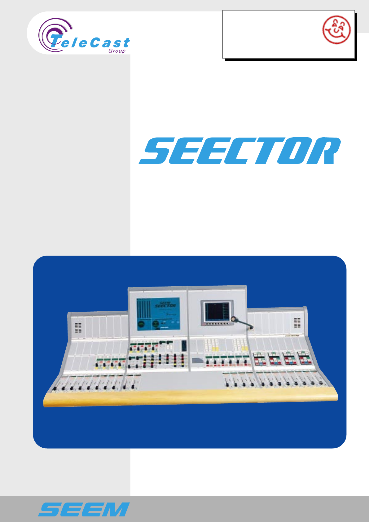
SEECTOR is the general name of a new family of digital mixers from
TeleCast Norge AS. The Seector user surfaces are dedicated
controllers for the digital audio processors Seem Seecor and NTP
625.
Seector mixers are configurable at order and include a range of
mixers from small desktop on-air mixers to large radio and TV
production consoles.
The Seector family is based on general modules that are all under
software control. These modules enable us to create a variety of
control surfaces for different applications.
Control surfaces can be made either with assign panels, with
dedicated channel controls or with a mix of both.
1.1 Console Philosophy
The Seector family is based on the well-established Seelect
principals. However the new consoles demand even more flexibility
than found in the Seelect.
This flexibility is maintained through a modular design where reliability
and customisation have been the main targets.
This section explains some basic guidelines for understanding the
Seector consoles.
1.1.1 Block diagram
The basic console functions are decided and customised during the
configuration process. All parameters needed to describe the
functions of the console are described in a block diagram, which is
stored in the audio rack. The user surface gets the required
information from the audio rack when the system is started. This
information is combined with the user configurable parameters from
the user set-up to form the rules for the user surface behaviour.
The block diagram shows the process interconnections and user setup possibilities that the audio rack offers to the user surface.
See Audio Rack documentation for details on block diagrams.
1.1.2 Source categories and properties.
The sources (or inputs) to the system are divided into several
categories. The categories can be sub-divided into two main groups.
• Inputs from persons
• Inputs from machines
A set of source properties defines the way the sources will behave
when selected into the console.
The properties include remote control functions, red light switching,
talkback possibilities and other features dedicated to each source.
2
seector00.doc 27.04.00
Page 5

SEECTOR User Manual
1.1.3 Destination categories and properties.
The destinations (or outputs) are also divided into two categories.
• Standard outputs
• Monitor outputs
A set of destination properties defines the way the destinations will
behave.
The properties include talkback possibilities, monitor options and
other features dedicated to each destination.
1.1.4 Talkback.
In general it is possible to talk to all outputs from anywhere. The block
diagram shows which combinations, which are allowed. When a
talkback is active a predefined microphone is connected to the output
for communication, and the ordinary audio is muted, dimmed or
redirected.
1.2 Seector Philosophy
1.2.1 Control access levels.
Some controls are more important than others. An availability
hierarchy is designed to give easy access to the most critical controls.
Three different access levels are available in the system concept.
• Directly (Primary)
• Assigned (Secondary)
• Menu selection (Tertiary)
Primary functions have a direct control through one-finger operation.
Secondary functions are accessed on a central assign panel after
pressing the assign button for a channel.
Tertiary functions are accessed through screen menus.
All primary functions are also available on the secondary and tertiary
control levels. All secondary functions are available using the tertiary
control level.
All controls can be available on any level depending on the installed
panels. It is also possible to give different sections of the console
different panel layouts.
1.2.2 Assign concept
Any channel strip can have parts of the assignable functions installed
as dedicated control panels. Logically these panels work in parallel
with the assign panel.
seector00.doc 27.04.00
When the dedicated control panels are installed the functions will be
handled on the primary level.
All fader strips have a large assign button. One and only one fader
strip has the assign button illuminated at a time. The assign panel is
displaying the settings for the assigned fader strip.
3
Page 6

SEECTOR User Manual
A user surface handles one assign panel which may be assembled by
several different panels.
1.2.3 Selections and lists.
The configurable nature of the console leaves many connections in
the block diagram open for the operator to connect. Sources must be
assigned to faders, mixing buses to outputs, insert points to channels
and many more.
Whenever the operator has to do a selection, the options are
presented in the form of lists displayed on the screen. The lists
appear when the selection is started (i.e. rotation detected) and stays
on the screen for a period of time. The new selection is established
as soon as the selection is stopped (i.e. end of rotation).
To avoid unnecessary selections in long selection lists the console
has a system to reduce the size of the lists. All selections are also
stored in the user presets.
1.2.4 Short and long push.
On some buttons there is a distinction between long and short
pushes. A short push activates a toggling function that is indicated by
the button illumination. A long push is detected when the button is
pressed down continuously for a longer period (Programmable.
Approx. 0.6s). The long push activates a momentary function without
changing the toggling status.
1.2.5 Routing concept
Routing is the operation where the input channels are connected to
the different summing buses. On the Seector there is no dedicated
routing switches. A long push on an assign switch activates the
routing status.
The involved faders are all input faders and those output faders that
have summing buses as sources.
Input channels
A long push on the assign switch on an input fader panel activates
the routing mode.
If the selected source is routed to a sum, the output fader will turn the
assign switch on.
The routing connection can now be toggled on and off by pushing the
output fader's assign switch.
One input can be routed to several sums.
Output channels
A long push on the assign switch on a destination fader panel with a
summing bus source activates the routing mode.
Any input fader panels routed to the summing bus is turned on.
The routing connection can now be toggled on and off by pushing the
input fader's assign switch.
4
seector00.doc 27.04.00
Page 7

SEECTOR User Manual
UCO
Routing status
The routing status is displayed in the assign window on the screen.
A separate routing menu gives also extra information about routing
status.
1.3 Configuration and User set-up
1.3.1 Configuration
The configuration of hardware and software includes all settings
related to the installation, and is not accessible to the operator. The
configuration is stored in the configuration files.
In this manual a C marks any section explaining configuration
options.
1.3.2 User set-ups
The user can alter the behaviour of the system by selecting different
user selections and options. These are stored in user set-ups that are
accessible to the operators. Consequently, several different user
profiles can be handled by the system.
In this manual any section explaining user options are marked by a
U.
1.3.3 Options
Several functions and panels described are not part of a standard
configuration. All sections related to this are marked with an O.
seector00.doc 27.04.00
5
Page 8
SEECTOR User Manual
2. Screen
A screen is included in the system for displaying purposes and for
menu dialogs and configuration.
In order to make screen operations safe some basic restrictions are
built into the system:
• All screen menus are placed in predefined positions to avoid any
vital information to be obstructed.
• Menus are never more than two levels deep.
• Only one menu can be open at any time. Opening a new menu will
close the previous.
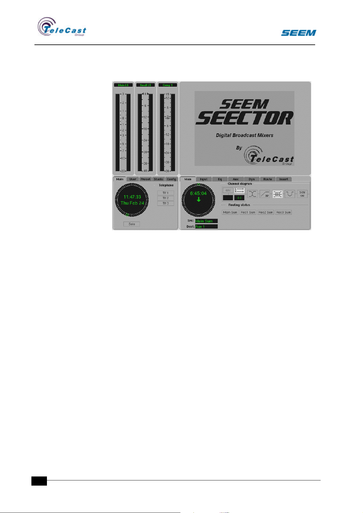
The screen area is divided into four sections that are explained in the
following sections.
• The display window
• The assign window
• The Status window
• The User window
6
seector00.doc 27.04.00
Page 9
SEECTOR User Manual
C
2.1 Display window
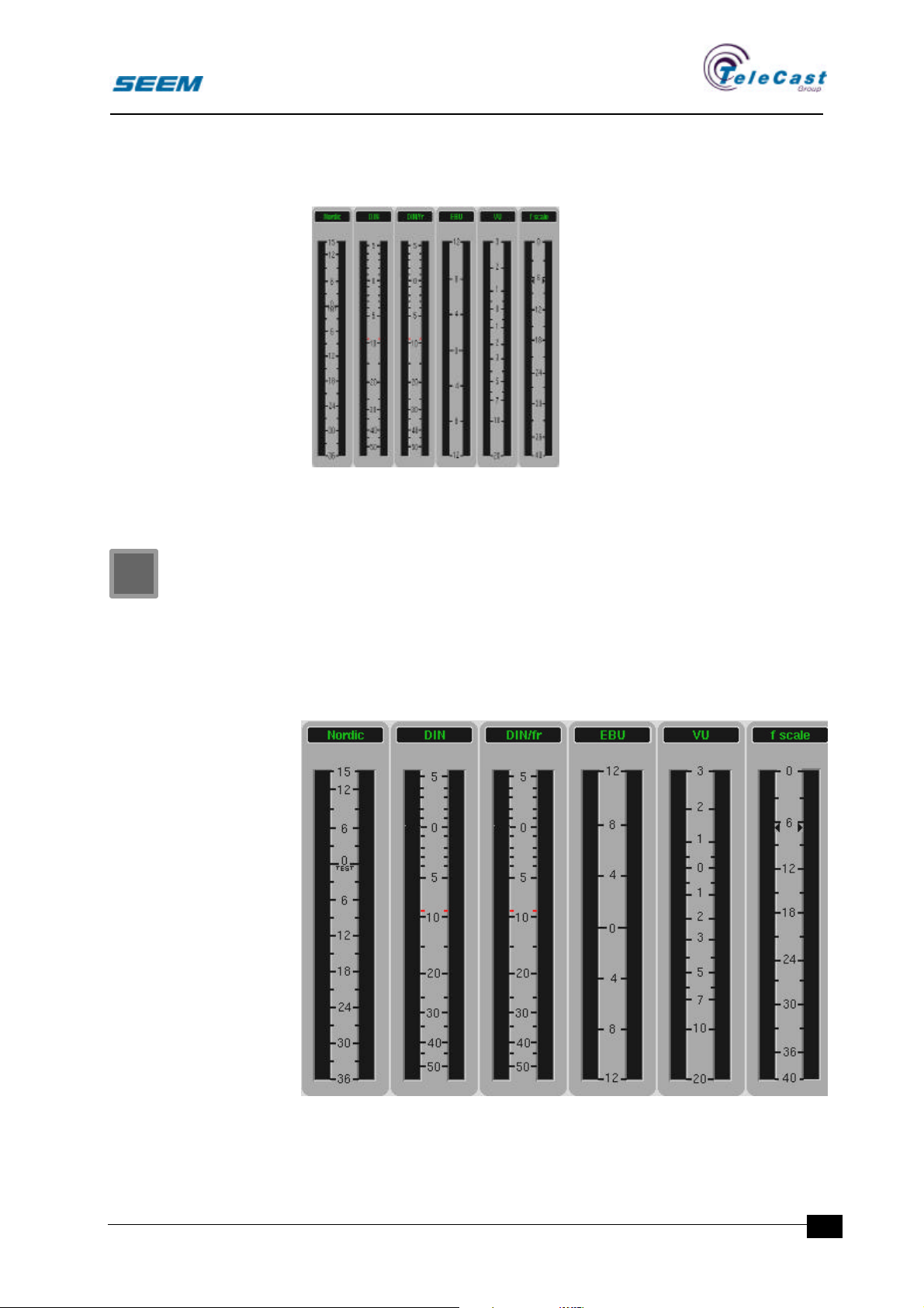
The display window contains the
level meters. The number of
meters can vary from 1 up to 4.
Different meter types are also
available.
The width of this window is
adjusted according to the
number of meters.
2.1.1 Title bar and overload
Every meter has a title bar where
the source name is written.
When the level exceeds a
predefined level the meter
presents an overload warning.
2.1.2 Display window configuration
The number of meters, the meter type and their source names are
specified during the configuration.
The overload level is also specified in the configuration menu.
The available types are PPM Nordic scale, PPM DIN scale, PPM
French scale, PPM digital FS scale, PPM EBU scale and VU meter.
seector00.doc 27.04.00
7
Page 10
SEECTOR User Manual
2.2 Assign window
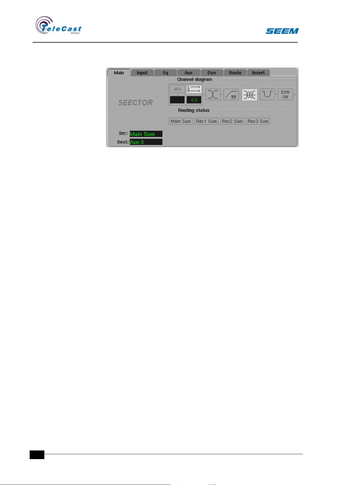
The assign window is an extension of the assign panel. Secondary
functions as well as more detailed information are shown in this
section.
The source and destination names are displayed in the assign
window.
The assign window is divided in several sections.
2.2.1 Channel diagram section
A simple diagram showing the channel processes is displayed here.
All processes are indicated as icons reflecting the process status.
2.2.2 Routing section
The routing section displays the selected routing status for a source.
All available destinations are shown.
The routing system is explained in section 1.2.5.
2.2.3 Stopwatch section
The stopwatch display shows the local counter for every source.
Preset value and up or down counting is indicated.
The stopwatch is explained in section 5.
2.2.4 Assign window menus
A number of menus are available in the assign window.
• Input menu
• Equaliser menu
• Dynamics menu
• Routing menu
• Auxiliary menu
• Insert menu
These are described together with the related functions.
8
seector00.doc 27.04.00
Page 11
SEECTOR User Manual
U
C
O
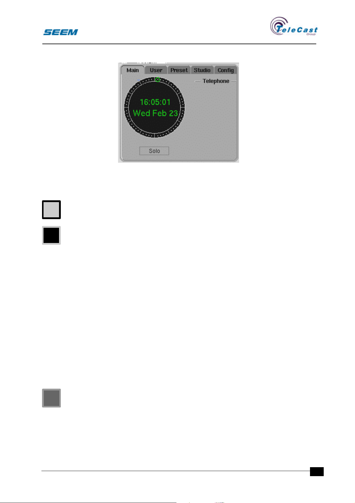
2.3 Status window
The status window gives global information on the user surface.
The status window is divided in two sections.
2.3.1 Real time clock section
The real time clock has a digital readout with an additional analogue
seconds readout.
The display can display both 12 and 24 hour formats.
The real time clock format is selected in the user set-up menu.
The date is also displayed.
The real time clock can run locally as a master or be synchronised
from the audio rack.
2.3.2 Status section
The status section displays status for the control room and connected
studios.
All system messages will be displayed in this area.
A number of menus are available in the status window.
• User menu
• Preset menu
• Studio menu
• Configuration menu
The menus are described together with the related functions.
2.3.3 Real time clock configuration
The synchronisation mode for the real time clock is selected and set
at the configuration stage.
seector00.doc 27.04.00
9
Page 12
SEECTOR User Manual
U
C
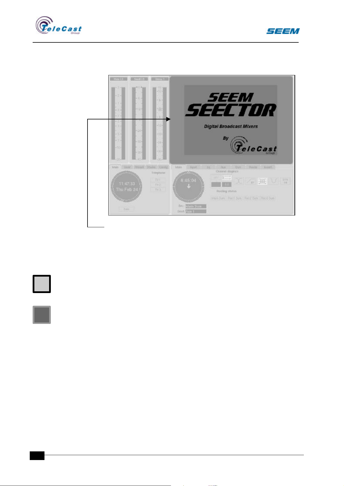
2.4 User window
The user window contains user specific programs not related to the
audio functions.
In this window it is possible to run third party software.
If no functions are selected for the user window the company logo
may be displayed.
2.4.1 User set-ups in user window
The user window function is selected in the user set-up menu’s user
window section.
User window configuration
The available options for the user window are set at configuration
stage.
2.5 Pointing Device
A pointing device is included to give easy access to the menus.
The pointing device has a fixed position. As standard, the system is
delivered with a Glidepoint unit.
2.5.1 Glidepoint operation
To single-click, double-click, drag and highlight functions of the
primary mouse buttons simply tap on the surface of the pad.
10
To click, lightly and crisply tap on the surface of the pad once. You
may use your fingertip, your fingerprint, your thumb or whatever is
comfortable for you.
seector00.doc 27.04.00
Page 13

SEECTOR User Manual
To double-click, apply two rapid taps to the pad. Remember, the
touchpad responds to very light touch.
To drag, draw or highlight, double-tap rapidly on the pad, holding
your finger down on the second tap.
To drag further than the surface, simply lift your finger and
reposition after reaching the edge of the pad.
2.5.2 Other pointing devices
Instead of the standard Glidepoint touchpad, the user may also use
an ordinary mouse. The user surfaces will in the future be delivered
with trackball as option.
seector00.doc 27.04.00
11
Page 14
SEECTOR User Manual
3. Dedicated Panels
Dedicated panels are used wherever direct operation on the primary
level is needed.
Dedicated panels are also used in areas without channel relationship
like studio selectors, transmission switches etc.
3.1 Fader Panel
3.1.1 General
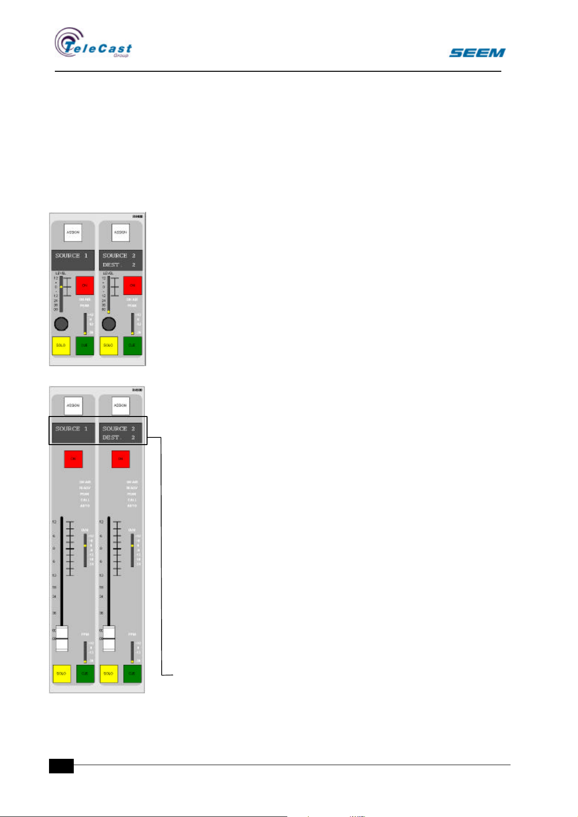
Fader strips exist in different versions. The large and the small faders
are almost identical in functions. However, the long smooth fader
used on the large fader module, is on the small module replaced by a
rotary level control. This is done in order to create a compact module
used mainly for auxiliary masters and other general-purpose level
controls.
The fader strips serve as control panels for both sources and
destinations. The distinction between input/source and
output/destination panels is indicated by the character display.
3.1.2 Controls
Assign
• Illuminated assign switch
The assign switch attaches all assignable panels and assignable
screen areas to the selected strip.
The assign switch enables routing at long pushes.
The assign switch has no effect on the audio.
One, and only one, assign switch is selected at a time.
Channel indicators
• 8-character source display
• 8-character destination display
• READY indicator
• ON AIR indicator
• PEAK indicator
• Conference call indicator
12
• Auto indicator
The source display shows the selected source name for the strip.
The destination display shows the selected destination name for an
output strip. For an input strip this display is blank.
seector00.doc 27.04.00
Page 15
SEECTOR User Manual
COUOU
The ready indicator shows the ready status for the selected source.
Sources can have a ready input connector and can be configured in
different ways.
The on air indicator shows that audio is floating through the channel.
Both the channel fader and the on-switch must be active to enable
the on air indicator and the audio channel.
An optional active chain selection will inhibit the on air indication if the
audio is not routed to an open output.
Remote start follows the on air indicator.
The peak indicator is on whenever the audio level in the channel is
above a level limit. The limit level is defined during configuration.
The conference call indicator indicates that a 1.9kHz call tone is
present on the conference input. For consoles without conference
systems the indicator has no effect.
The auto indicator is illuminated when a remote control system or a
preset changes the fader value to another position than the fader
knob value.
Channel PPM
All fader strips may have a separate PPM meter. This is a lower
quality meter with a range from -36dB to +12dB.
The main purpose of the meter is to enable the user to see that audio
is present on the input.
Channel dynamics meter (Large fader only)
A dynamics meter may be included in the fader strip showing the
amount of compression or expansion.
Fader section (Large fader)
• Fader
• Fader switch
• Illuminated on switch
Level control section (Small fader)
• Level rotary control
• Light bar displaying the level setting
• Illuminated on switch
Whenever the fader or light bar is in the extreme down position the
fader switch is off.
The on switch toggles the channel on and off.
The indicator in the on switch is an indication for the on switch setting.
seector00.doc 27.04.00
In the user set-up menu several options shall be selected for the on
switch.
ON SWITCH ALWAYS ON locks all on switches in their on position.
ON SWITCH OFF BY CLOSING FADER. Whenever the fader is set
to its off position, the on switch is also switched off.
13
Page 16
SEECTOR User Manual
U
U
ON SWITCH DEFAULT ON sets all ON switches to on position at
system power up and at user set-up changes.
Cue system
• Illuminated CUE switch
• Illuminated SOLO switch (Optional)
The cue switch serves several functions:
Long push gives momentary action depending on the selected
source.
• When the source is of category machine, the monitoring changes
to channel cueing mode where start and rewind messages are
sent.
• When the source is of category person, talkback is activated.
• For output faders a long push is activating talkback.
Long pushes are momentary and do not change the indicator.
Short push toggles PFL mode on and off.
When short pushes toggles PFL, the indicator shows PFL status.
In the user set-up menu several options can be selected for the cue
switch:
PFL cut on open fader. This option disables the PFL whenever the
channel is on air.
PFL interlock. This option gives only one active PFL channel at any
time. Any other channel with active PFL will be released.
PFL switches on when a talkback is released.
The SOLO switch connects the channel to the monitoring system for
listening to the selected channel only.
SOLO interlock. The SOLO switches are mutual exclusive.
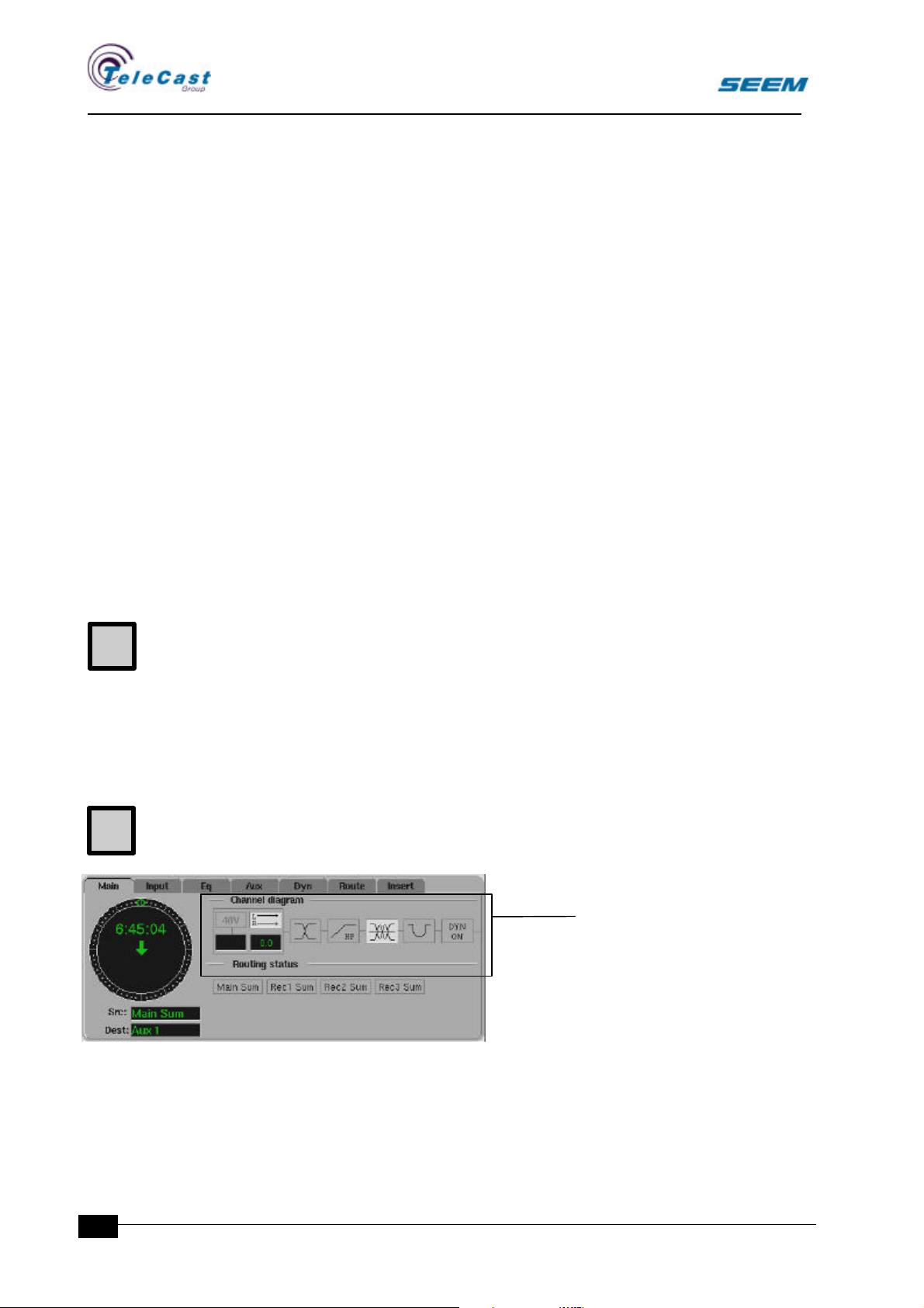
3.1.3 Routing section in
assign window
All valid destinations are
indicated in the routing
section. Whenever a routing
to any of these is on this is
indicated in the routing
section.
14
3.1.4 Routing menu
This menu is a future option.
seector00.doc 27.04.00
Page 17
SEECTOR User Manual
U
4. Assignable panels
Secondary functions are accessed through an assign panel.
4.1 Main assign panel
4.1.1 General
The main assign panel displays the basic settings for one strip in the
system. Activating the assign function on any fader strip displays the
settings for that specific strip.
The settings can now be adjusted, and are stored even when the
assign panel is attached to another strip.
All sources and destinations in the system have individual settings.
4.1.2 Controls
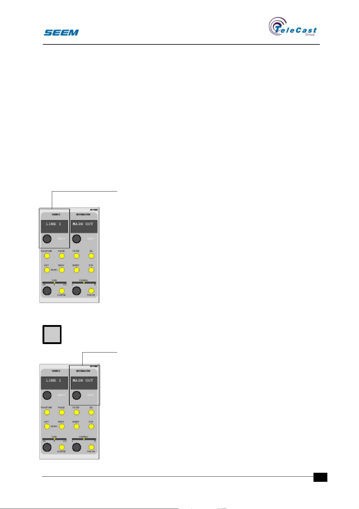
Source select
• Source select rotary control
• 8-character display
• Availability indicator (SELECT)
A rotary control with detents selects a source for the assigned strip.
While the control is turned the source list is shown in the monitor
assign window, and the actual selected source is shown in the panel
displays.
If a source is occupied by another strip, the colour is changed to
passive in the screen list, and the source is skipped on the panel
when turning the rotary control.
If the channel is on air, source select is not permitted and the
availability indicator is off.
Every strip holds its own source reduction list that can reduce the
amount of sources available for the given strip. The source reduction
lists are defined and stored as part of the user set-up.
Destination select
• Source select rotary control
• 8-character display
• Availability indicator (SELECT)
seector00.doc 27.04.00
A rotary control with detents selects a destination for the assigned
strip.
When a destination is selected the strip is defined as an output strip.
The channel output is connected to this output only.
Input strips do not have any destination selected and routing is
performed as described in the routing section for the faders.
Only one strip can select a given destination at a time. The colour in
the destination list shows which destinations that are occupied.
15
Page 18
SEECTOR User Manual
U
While the control is turned the destination list is shown in the monitor
assign window and the actual selected destination is shown in the
panel displays.
Selecting a destination changes all settings for the strip including
source selection.
One of the destination options is a blank no-selection. When this is
selected the strip is redefined as an input/source strip.
If the channel is on air, destination select is not permitted and the
availability indicator is off.
Every strip holds its own destination reduction list that can reduce the
amount of destinations possible for the given channel. The
destination reduction lists are defined in the user set-ups, and is
stored as part of the user set-up.
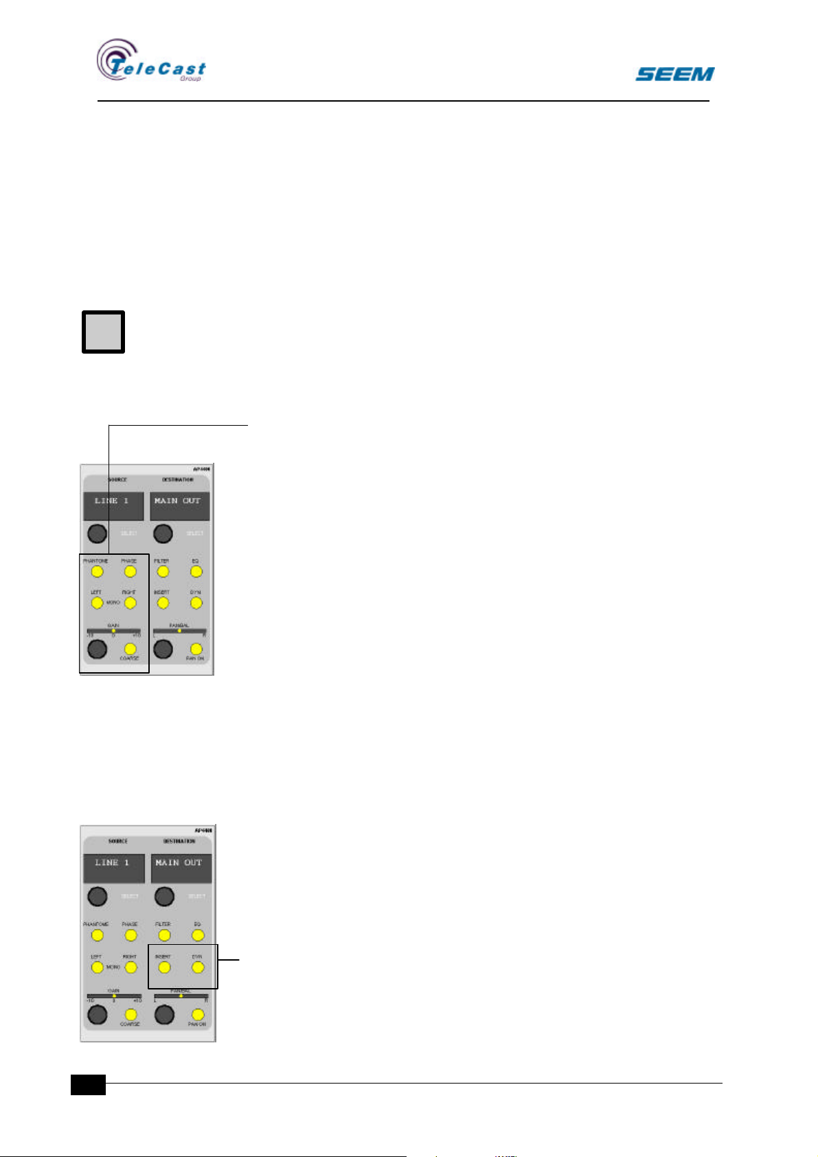
Input controls
• Gain rotary control
• Light bar
• Illuminated Left switch
• Illuminated Right switch
• Illuminated 48V switch (Microphone source only)
• Illuminated coarse gain switch (Microphone source only)
• Illuminated Phase shift switch
The gain rotary control adjusts the level of the source between given
fixed limits. The light bar indicates the gain setting.
Two switches marked left and right selects which input to be used.
When no switch is selected the source is treated as stereo.
When one switch is selected this input is used for both left and right
output.
When both are selected the channel uses both left and right input in
mono sum.
Coarse gain adjustments are performed with the gain rotary control
when the coarse switch is selected.
The 48V phantom power switch is enabled for microphones only.
The phase switch reverses the phase of the source signal. For stereo
sources only the left input is reversed when active.
16
Channel controls
• Illuminated Filter switch
• Illuminated Equaliser switch
• Illuminated Insert switch
• Illuminated Dynamics switch
seector00.doc 27.04.00
Page 19
SEECTOR User Manual
C
The filter switch switches the filter in or out of circuit.
If a filter is not available for the source, the switch has no effect, and
the filter section is dark.
The equaliser switch switches the equaliser in or out of circuit.
If an equaliser is not available for the source, the switch has no effect,
and the equaliser section is dark.
The insert switch switches the insert point in or out of circuit.
If an insert point is not available or defined for the source, the switch
has no effect, and the insert section is dark.
The dynamics switch switches the dynamics section in or out of
circuit.
If a dynamics section is not available or defined for the source, the
switch has no effect, and the dynamics section is dark.
The block diagram gives the availability.
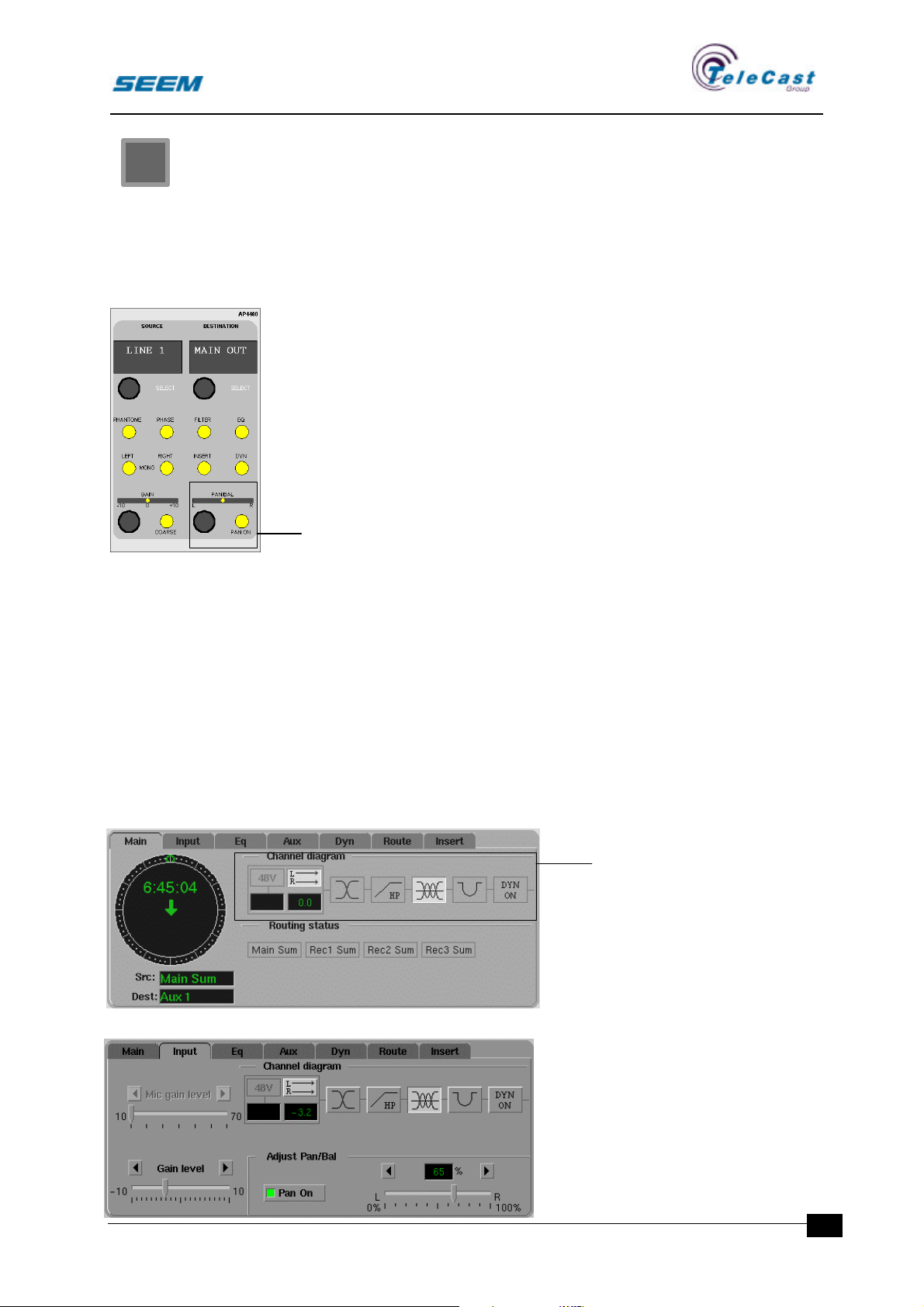
Pan/Bal control
• Pan/bal rotary control
• Light bar
• Pan/bal on switch
For mono sources the rotary control position the audio in a stereo
image.
For stereo sources the rotary control adjusts the level of left and right
channel.
When the pan switch is not active the Pan/Bal rotary control has no
effect, and audio is routed equally to both left and right destination.
4.1.3 Input section in
assign window
In the assign window channel
diagram the mono/stereo
mode and gain settings are
shown in the input icon.
seector00.doc 27.04.00
4.1.4 Input menu
This menu shows detailed
information about the source
properties. All settings
performed by the main assign
panel are available in this
menu.
17
Page 20
SEECTOR User Manual
C
Mono/stereo mode
The same information as set by the stereo/mono switches.
Gain and panning
The same information as set by the gain and pan controls.
Channel control
The same information as set by the channel control switches.
4.2 Auxiliary panel
4.2.1 General
In addition to the outputs available through the routing system a
number of auxiliary outputs are available.
Auxiliaries are defined as stereo or mono during audio rack
configuration
The auxiliary panel described is the assignable auxiliary panel.
More than one auxiliary panel can be installed for an increased
number of auxiliary send controls.
C
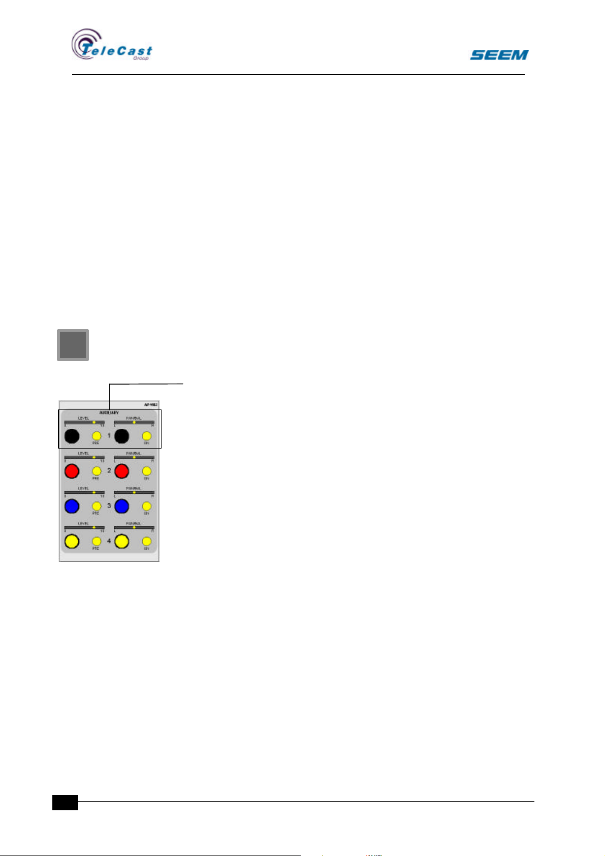
4.2.2 Auxiliary send controls
• Level control rotary control
• Pan/Bal control
• Pan/Bal light bar
• Illuminated pre switch
• Illuminated on switch
The auxiliary panel contains 4 similar sections giving 4 auxiliaries.
.
The level control adjusts the level sent from the channel to the
auxiliary sum. When the on-switch is off the aux send is muted.
The signal is taken from post channel fader, and for stereo auxiliaries
also post channel balance control.
The auxiliary pan/bal control has no effect on post fader auxiliaries.
When the pre switch is active the audio is taken pre channel fader
and for stereo auxiliaries the audio is also taken pre channel balance.
The auxiliary pan/bal control has the same effect as for the channel
pan/bal control.
18
seector00.doc 27.04.00
Page 21
SEECTOR User Manual
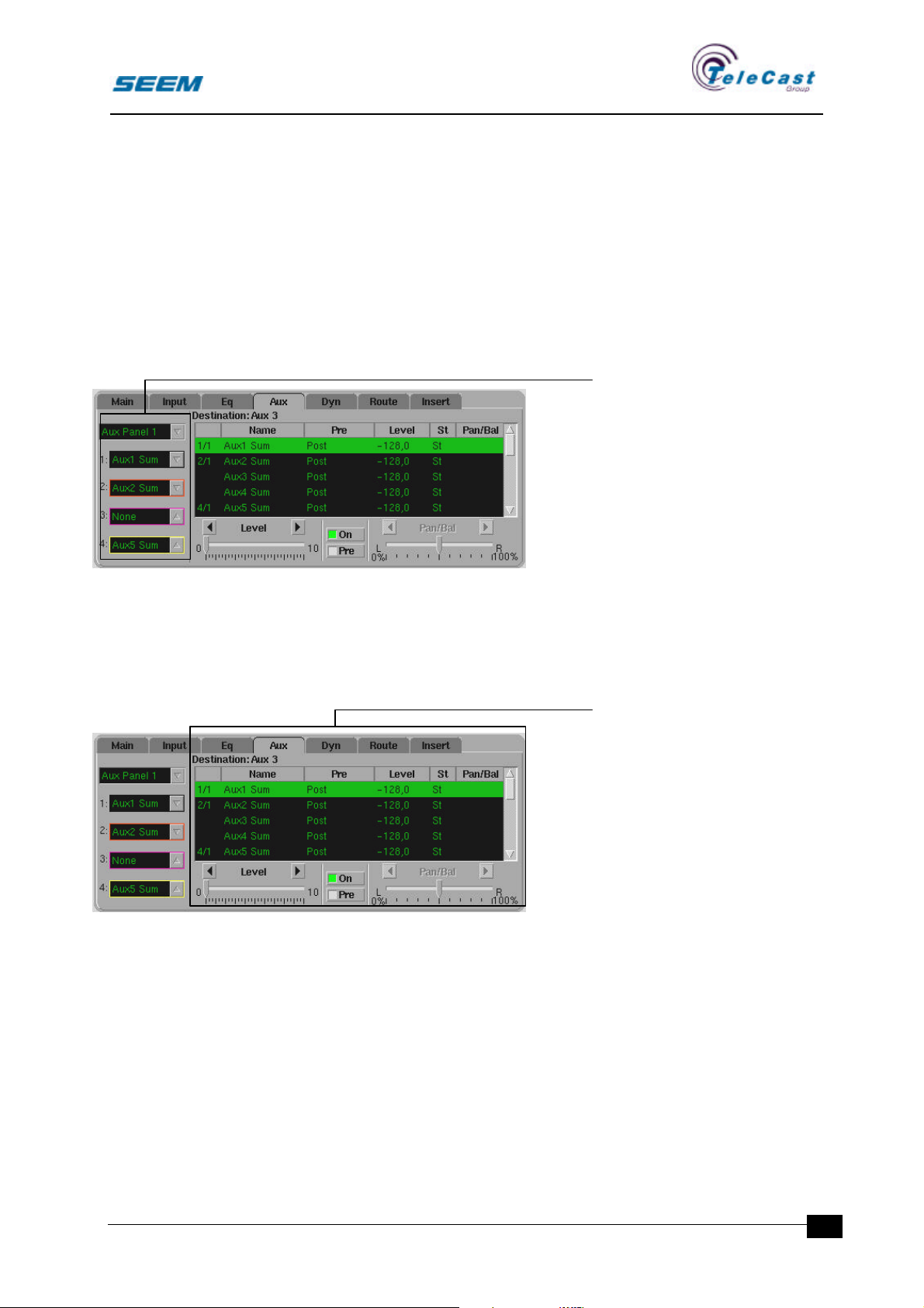
4.2.3 Auxiliary menu
An auxiliary menu is available which enhance the capabilities of the
auxiliary system. In this menu a great number of auxiliary sends are
available and attached to the panel rows or adjusted directly.
This is an efficient tool for controlling rarely used auxiliaries
The menu consists of two sections. The control section is global, and
not limited to the assigned strip, while the aux send section is a
standard assign area.
Controls section
This section selects which
auxiliaries that are controlled
by the auxiliary panels.
When the pointing device is
selecting the upper window
one of the auxiliary panels are
selected.
For this panel any auxiliary
can be connected to the panel
rows.
Every panel row has its own selection window.
When an auxiliary is selected for a panel row it is removed from
further selections.
Aux sends section
All auxiliary outputs are listed
by name. All controls are
listed, and pointing and
replacing from keyboard can
make changes.
The leftmost column indicates
if the auxiliary is attached to a
panel row.
By selecting one of the
auxiliaries in the table this can
be adjusted by the controls
under the aux table.
4.3 Filter panel
4.3.1 General
All channels can have a filter switched into the circuit. Various filter
algorithms with different controls requires different panels.
The basic filter section is a fixed high pass filter with no controls.
In the future filter panels will be available.
seector00.doc 27.04.00
19
Page 22
SEECTOR User Manual
O
C
4.3.2 Filter controls
No controls are available.
Future option.
4.3.3 Filter section in assign window
The filter icon in the assign window channel diagram indicates when
the filter is switched into circuit.
4.3.4 Filter menu
No menu is available.
Future option.
4.4 Equaliser panel
4.4.1 General
All channels can have an equaliser switched into the circuit. Various
equaliser algorithms with different controls requires different panels.
The equaliser panel described is the assignable equaliser panel.
Dedicated equaliser strips may have other controls.
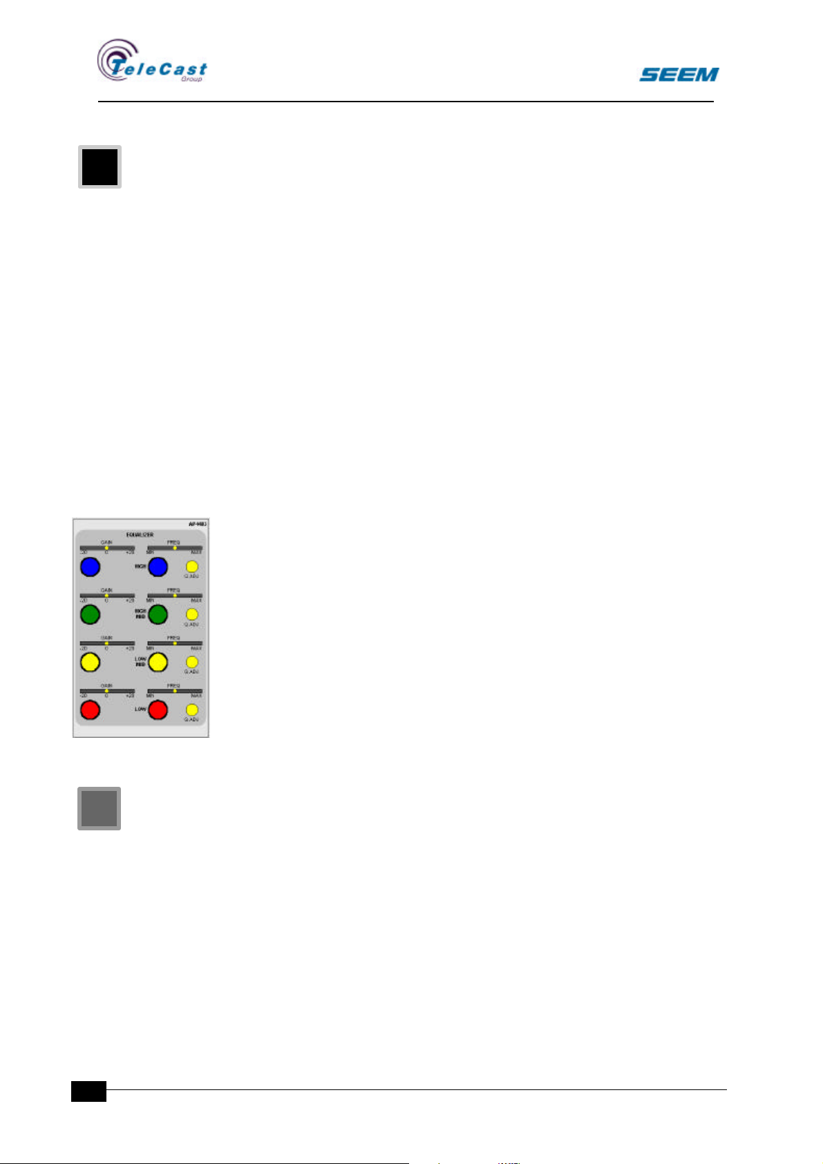
4.4.2 Equaliser controls
• Level adjustment rotary control
• Level light bar
• Frequency adjustment rotary control
• Frequency light bar
• Illuminated Q-value switch
• The equaliser panel contains 4 similar sections.
If the main assign panel equaliser switch is inactive the complete
equaliser panel is inactive.
The level adjustment rotary control adjusts the level at the given
frequency between given limits for the assigned channel.
The centre frequency is adjusted between given limits by the
frequency rotary control.
While the Q-value switch is active adjustments on the frequency
rotary control adjusts the Q-value for the equaliser section.
The number of LEDs in the frequency light bar that is on indicates
this.
20
A low Q-value will have a broad frequency array while the highest Qvalue will have only one LED illuminated.
4.4.3 Equaliser section in assign window
In the assign window channel diagram the curves of the equaliser are
shown as an icon. A passive icon indicates equaliser bypass.
seector00.doc 27.04.00
Page 23
SEECTOR User Manual
U
O
4.4.4 Equaliser menu
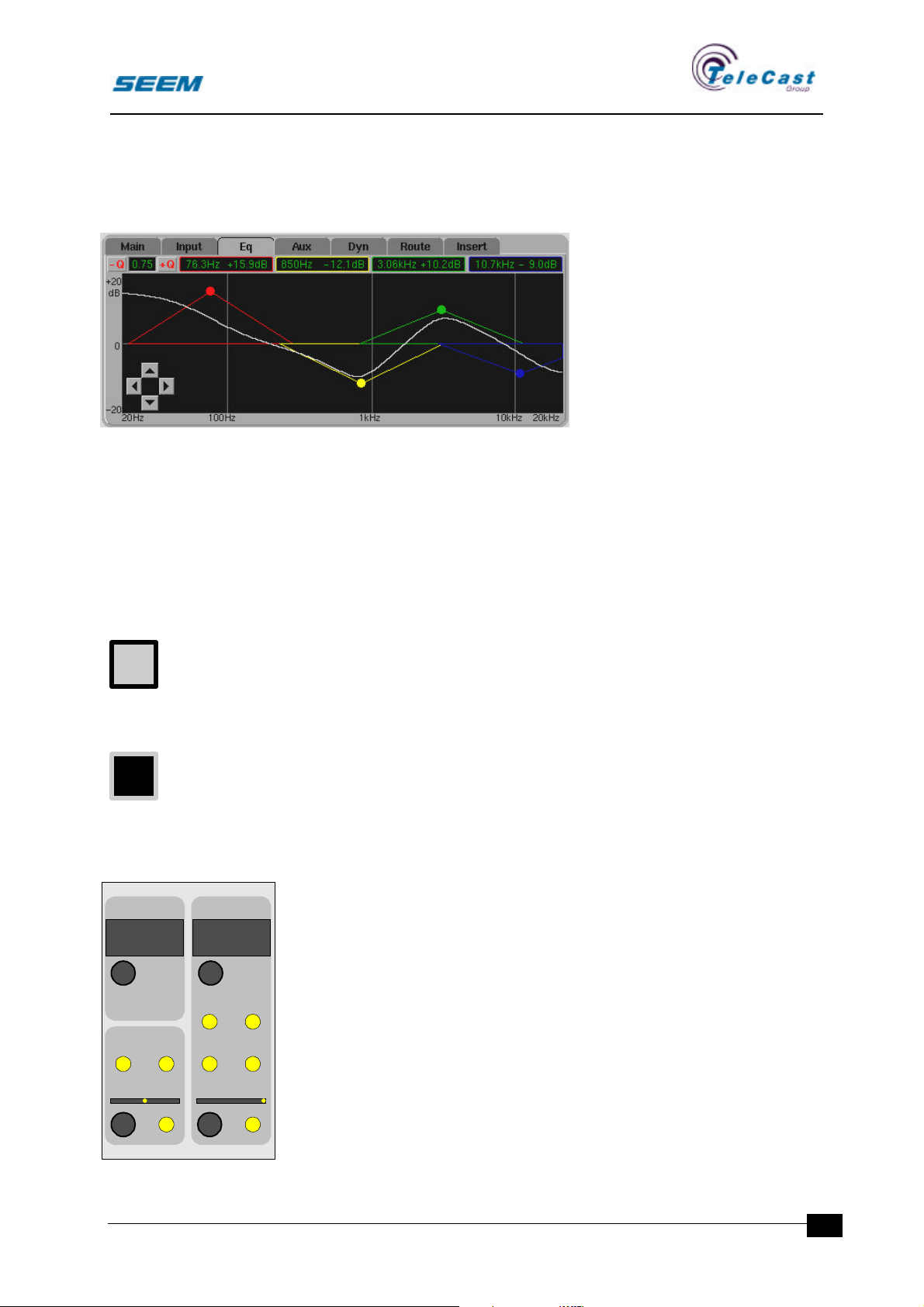
This menu shows detailed information about the equalisation in the
channel. An ordinary gain vs. frequency plot is shown with the bands
shown as triangles. The width of the baseline indicates the Q-value.
Above the plot the exact
values for gain and frequency
are shown. In the upper left
corner the Q-value is shown.
This can be adjusted by + and buttons. The band that is
shown is selected by clicking
either on the coloured dot in the
plot or the value field for the
right band.
By clicking on a value field a
four arrow cross is shown. This can now be clicked for fine
adjustments. A second click on the value field removes the arrow
cross.
Changes on any equaliser control are shown in the display.
Dragging with the pointing device changes the level and frequency.
All changes are indicated on the hardware panel.
Also a fine mode changes the range of level adjustments to +/-3 dB.
A user set-up option opens the equaliser menu whenever an
equaliser control is operated.
4.5 Insert panels and processes
4.5.1 General
To enhance the functionality of the channel extra processing can be
inserted in the channel on demand. These processes normally
require too much processing power to be distributed in every channel.
External equipment will also in some cases be inserted in a channel.
Insert processes are either internal processes within the console,
INSERT DIRECT OUT
EXTERNAL
SELECT
MS/AB DECODE
WIDTH MS/AB
OUT 13
SELECT
SOURCE N-1
PRE
POST
FADER
FADER
AP4405
probably with their own panels, or they are pointing at an output input pair of connectors for connecting external equipment.
The insert points are placed in the block diagram during configuration
of the audio rack. In this way a high degree of flexibility is maintained.
4.5.2 Insert point controls
Insert process selection rotary control
• 8-character display
WIDTH
M X2
ST
IN
seector00.doc 27.04.00
LEVEL
-00 +6
• Availability indicator
0-6
ON
If the main assign panel insert switch is inactive the complete insert
panel is inactive.
A rotary control with detents selects an insert process for the
assigned channel.
21
Page 24
SEECTOR User Manual
O
Every strip holds its own insert list that reduces the amount of insert
processes available for the given channel. The insert lists are defined
in the user set-ups, and is stored as part of the user set-up.
The insert list is shown on the screen while the control is rotated.
If an insert process is occupied by another channel, the colour is
changed to passive in the screen list, and the insert process is
skipped in the panel display when turning the rotary control.
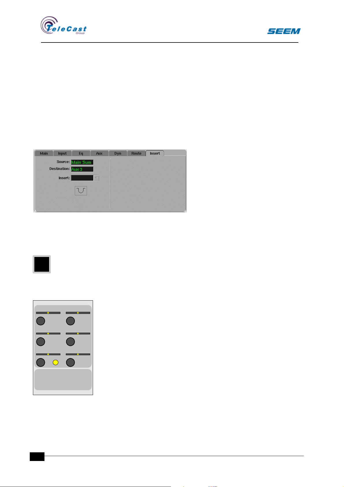
4.5.3 Insert section in assign window
An insert icon is available in the assign window to indicate which
process that is connected and also where in the block diagram the
insert point is located.
4.5.4 Insert menu
A menu is available to make selection
without dedicated panels.
4.6 Dynamics panel
4.6.1 General
All channels can have a compressor/expander switched into the
circuit. Various algorithms with different controls requires different
panels.
The dynamics panel described is the assignable dynamics panel.
Dedicated dynamics strips may have other controls.
COMPRESSOR
ATTACK RELEASE
10us
100ms 10ms 100s
REF.LEVEL SLOPE
HOLD LEVEL MAX GAIN
0dB-20dB
0dB-40dB
-100dB
1:1 1:10
0dB 20dB
AP4404
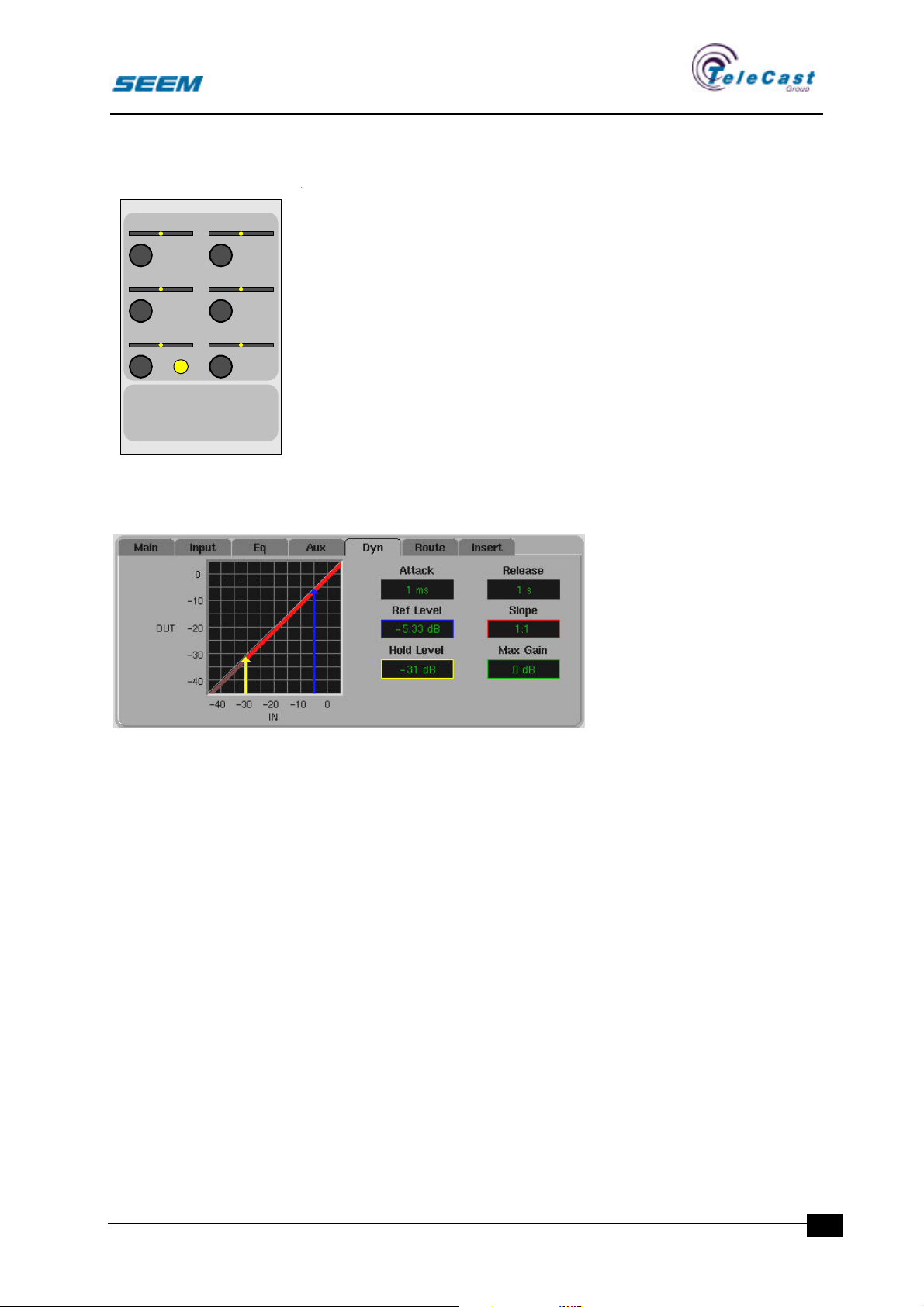
4.6.2 Dynamics controls
• Attack adjustment rotary control
• Release adjustment rotary control
• Ref. level adjustment rotary control
• Slope adjustment rotary control
• Hold level adjustment rotary control
• Illuminated –100dB hold level switch
• Max gain adjustment rotary control
22
If the main assign panel dynamics switch is inactive the dynamics
section is bypassed.
The attack and release adjusts the timing characteristics for the
dynamics section.
seector00.doc 27.04.00
Page 25
SEECTOR User Manual
The ref. level control sets the level where the compressor gives no
gain correction.
COMPRESSOR
ATTACK RELEASE
10us
100ms 10ms 100s
REF.LEVEL SLOPE
HOLD LEVEL MAX GAIN
0dB-20dB
0dB-40dB
-100dB
1:1 1:10
0dB 20dB
AP4404
The slope control sets the compression ratio.
The max gain control gives a maximum gain value and thus defines
the knee point of the compressor together with the slope and ref.
level.
The hold level control sets the minimum trigger level. Any audio input
below this level will not affect the compressor. The separate switch
will set the hold level to –100dB.
4.6.3 Dynamics section in assign window
In the assign window channel diagram the curves of the dynamics are
shown as an icon. A passive icon indicates dynamics bypass.
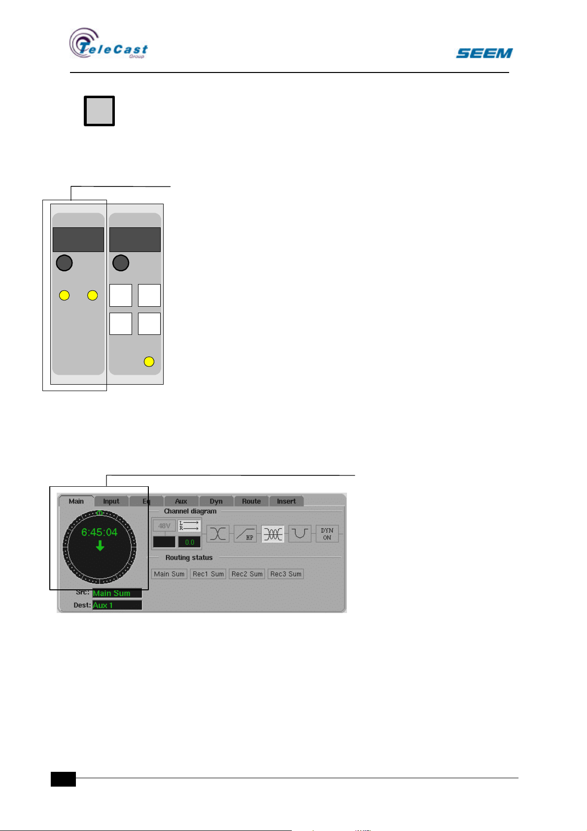
4.6.4 Dynamics menu
This menu shows detailed
information about the
dynamics section in the
channel.
Changes on any dynamics
control are shown in the
display.
Dragging with the pointing
device shall also change the
parameters.
These changes are also indicated on the hardware panel.
A field for each control shows the exact value.
A square area shows the input / output relationship.
The axis are marked from –40dB to 0dB. A dotted line marks the 1:1
function.
An arrow from the x-axis to the dotted line indicates the ref. level.
A line indicates the Slope with an angle given by the input / output
relationship.
An arrow above the dotted line indicates the maximum gain. The
location of the arrow is where the arrow exactly fits between the
dotted line and the slope line. On the left side of the maximum gain
arrow the slope line makes a bend and follows a 1:1 angle. This point
is called the knee point of the compressor.
The hold level is indicated by an arrow from the x-axis up to the slope
line at the selected dB value. On the left side of the arrow the slope
line shall have a darker colour or thinner line to indicate that the line is
under the working limit. Audio level below this level will not affect the
compressor.
seector00.doc 27.04.00
23
Page 26
SEECTOR User Manual
U
A user set-up option opens the dynamics menu whenever an
dynamics control is operated.
5. Stopwatch panel
5.1.1 General
STOPWATCH USER SETUP
AP4401
00:00:00 USER-001
All sources have a separate stopwatch timer running independently.
5.1.2 Stopwatch controls
• Preset time display
DOWN UP
PRESET
1
PRESET
3
SELECT
PRESET
2
LOAD
USER
WRITE
• Preset time rotary control
• Illuminated Down from preset switch
• Illuminated Up from 0 switch
Every source has its separate stopwatch timer. Whenever the fader is
on air the watch is running. The start point is either 0 when counting
upwards or the preset value when counting down. When the timer
reaches 0 it switches to upward counting.
Whenever a stopwatch that counts downwards reaches 0 it switches
to upward counting.
The preset value can be altered while the timer is running.
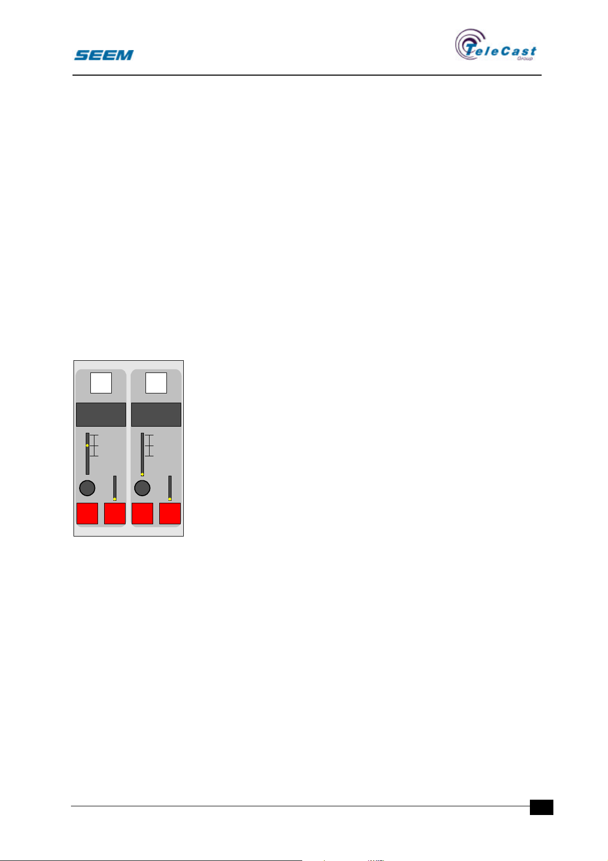
5.1.3 Stopwatch section in assign window
The watch is displayed in the
assign window. If neither up or
down is selected the stopwatch
display is blanked
24
seector00.doc 27.04.00
Page 27
SEECTOR User Manual
6. Monitoring
6.1 General
The monitoring panels are special panels for controlling the
monitoring facilities. The number of monitor outputs is part of the
configuration.
The monitoring panels consist of monitor level controls with dim and
mute, monitor selectors and monitor function controls.
The user menu adds extra functions to the monitor outputs.
A number of monitoring panels can be installed to control different
speaker and headphone outputs.
6.2 Monitor panel controls
ASSIGN ASSIGN
SOURCE 1
MAIN LS
LEVEL
12
+
0
12
24
36
00
+12
0
-12
-36
MUTEDIM MUTEDIM
SOURCE 2
SMALL LS
LEVEL
12
+
0
12
24
36
00
M4400
6.2.1 General
The monitor panel is similar to the small fader panel. The only
difference is that a mute and dim switch replaces the cue and SOLO
switches.
6.2.2 Controls
Illuminated assign switch
PEAKPEAK
By using a short push on the assign switch the assign function
+12
becomes available. Only source and destination selections are
0
-12
available, and the rest of the assign panel is disabled.
-36
The assign switch has no effect on the audio.
One, and only one, assign switch is selected at a time.
Channel indicators
• 8-character source display
• 8-character destination display
The source display shows the selected source.
The destination display shows the selected monitor output name.
Level control section
• Level rotary control
seector00.doc 27.04.00
• Light bar displaying the level setting
The level is adjusted with the rotary control and the level setting is
shown on the light bar.
Additional switches
• Illuminated DIM switch
• Illuminated MUTE switch
25
Page 28
SEECTOR User Manual
C
C
The two buttons overrides the level control.
DIM lowers the level by a selectable level. This level is set in the user
menu.
MUTE completely cuts any audio on the output.
MUTE has priority over DIM.
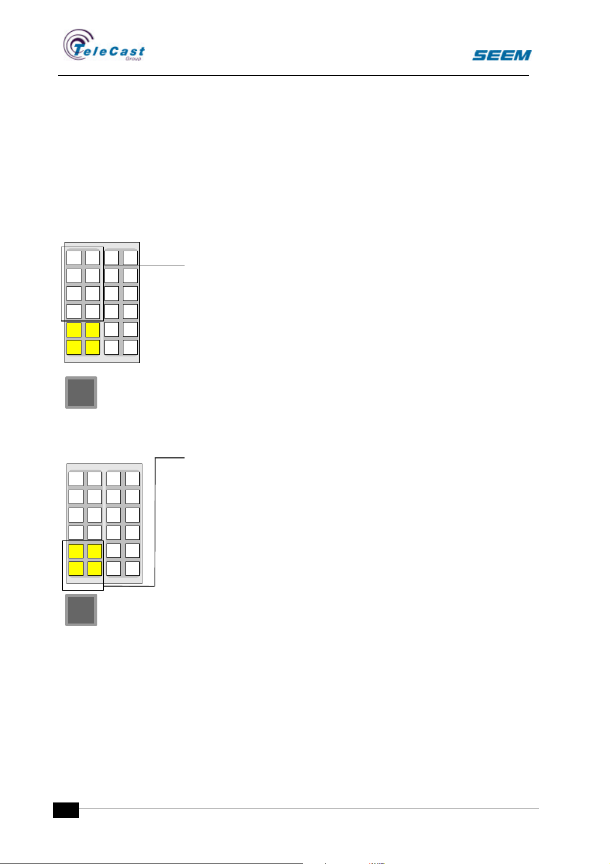
6.3 Monitor selection panels
1 2
3 4
5 6
7 8
MONO
LEFT
PHASE SIDE
S4400
1 2
3 4
5 6
7 8
9 10
MONO
11 12
A number of separate switches give a possibility for fixed source
selections for the monitor for easier access to commonly used
sources. Each switch is labelled with a source name that is selected
when the switch is pressed. Only one source is available
simultaneously. A second push on the selected switch releases the
selection.
When no dedicated selection is made, the source in the monitor
source display is selected.
These switches are freely programmable, and can be assigned to any
monitor output as well as any valid monitoring source during
configuration.
6.4 Monitor function selectors
Separate switches gives extended monitoring facilities.
• Mono sum
• Mono sum to left speaker only
• Side changes
• Phase reverse
• Selection follows another monitor
• Speaker swap
1 2
3 4
5 6
7 8
MONO
LEFT
PHASE SIDE
S4400
1 2
3 4
5 6
7 8
9 10
MONO
11 12
These switches are freely programmable, and can be assigned to any
monitor during configuration.
6.5 Monitor options menu
The user menu has a monitor options section.
Several useful options are available for each monitor output
individually.
• Mute while OnAir
• Dim while OnAir
• Source Change while OnAir
• Dim while talkback
26
seector00.doc 27.04.00
Page 29

SEECTOR User Manual
C
Mute and dime controls the output level of the monitor while the
monitor location is on air. This means that whenever a microphone in
that room is open the level is either muted or dimmed.
When source change while OnAir is selected the monitor output will
automatically change to the selected source whenever the monitor is
on air. This is useful when a "mix minus studio" is created for the
studio speakers. This selection can also be used in conjunction with
dim while OnAir.
Dim while talkback sets the dimming level for the monitor output
whenever a talkback is originated in that room. This dim level is also
used by the DIM switch on the monitor panel.
6.6 Other monitor options
During configuration the destination of PFL, SOLO and talkback is
decided. These can be directed to replace the selected audio in any
monitor output.
seector00.doc 27.04.00
27
Page 30
SEECTOR User Manual
C
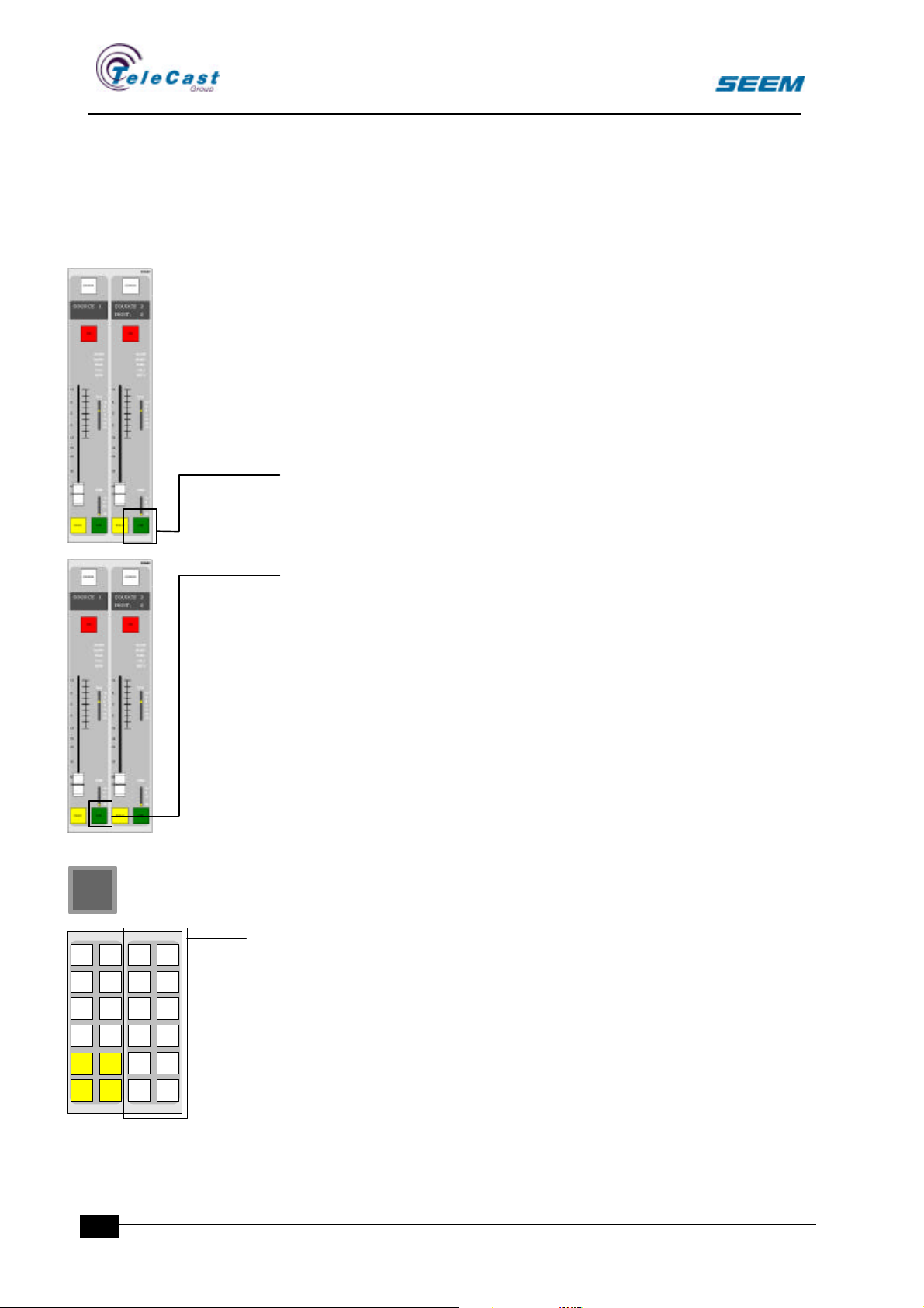
7. Talkback
7.1 General
Talkback connects a defined talkback source to an output while a
talkback switch is pressed.
Several methods may be used to give talkback to an output.
• Long push on the CUE switch on a destination fader
• Long push on the CUE switch on a source fader
• Push on a dedicated talkback switch
These methods are all equal.
7.1.1 Talkback on destination CUE switches
When the CUE switch is pushed, the talkback is directed to the
destination shown in the display. This assumes that talkback to this
destination is allowed in the configuration.
1 2
3 4
5 6
7 8
MONO
LEFT
PHASE SIDE
7.1.2 Talkback on source CUE switches
When the CUE switch is pressed, the console checks the source
properties to find a link to any talkback destination.
If a talkback destination is found, talkback is activated.
7.1.3 Dedicated talkback switches
S4400
1 2
3 4
5 6
7 8
9 10
MONO
11 12
The talkback panel is an addition to the talkback by cue switches.
A number of configurable destinations are given fixed switches to
extend the number of talkback destinations.
These switches are freely programmable, and can be assigned to any
talkback destination during configuration.
Short pushes toggles while long pushes are momentary.
28
seector00.doc 27.04.00
Page 31
SEECTOR User Manual
8. User set-up
The console enables the operator to customise their working
environment. These settings are found in the user menu. All settings
stored under the user menu are part of the user setup.
8.1 User menu
8.1.1 General
All special options the operator can specify are selected
under the user menu. All settings here are part of the saved
user setups.
Changes in the setups give immediate effect.
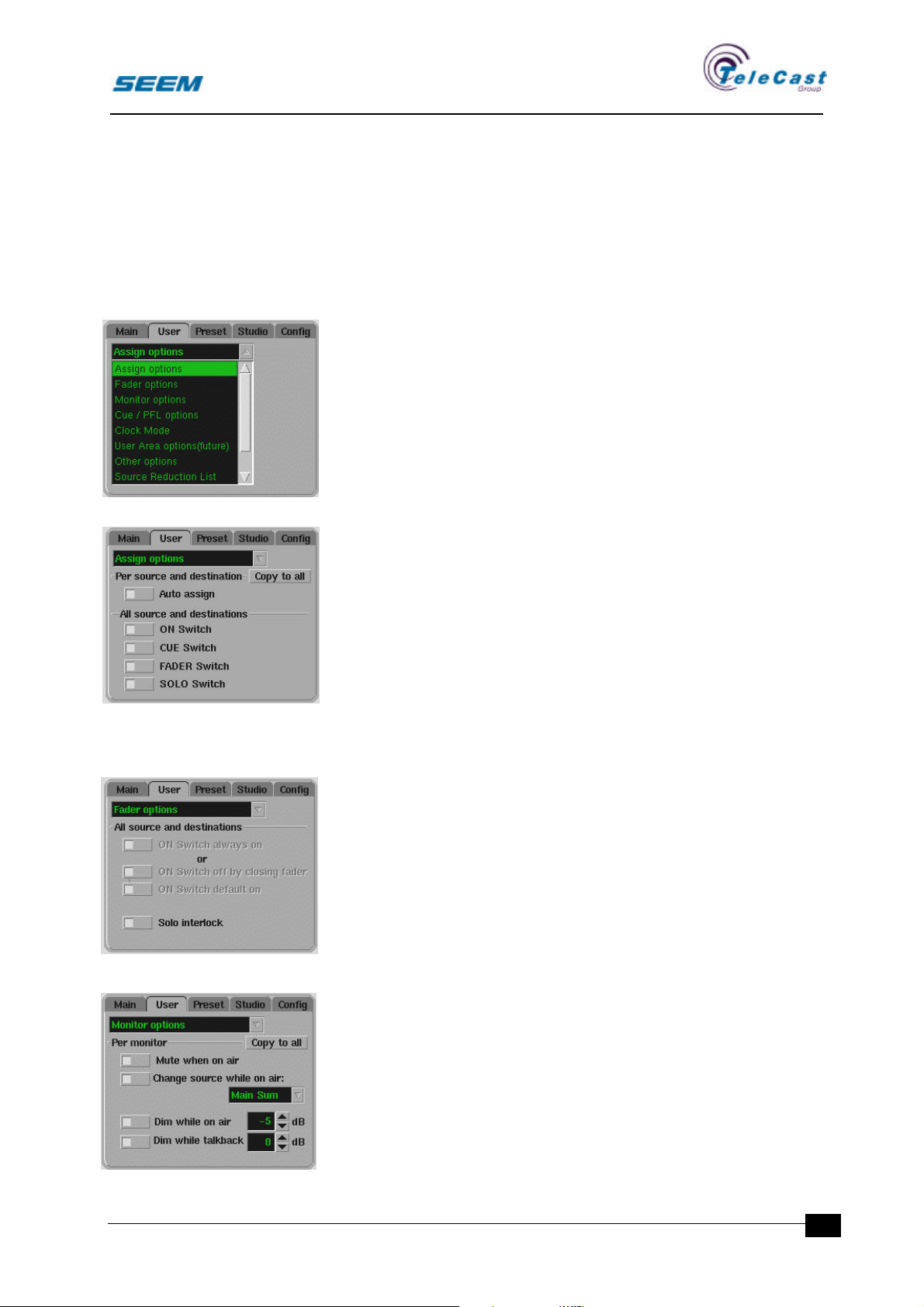
The following parameters are defined in the user set-up
menu:
8.1.2 Assign options
This setting is done for every source and destination. Press
the assign switch to select.
The general AUTO ASSIGN switch enables or disables the
complete autoassign function. When the function is
enabled, the following switches can be set to perform
autoassign:ON-switch is activated
• CUE-switch is activated
• SOLO-switch is activated
• FADER switch is activated
8.1.3 Fader options
ON SWITCH ALWAYS ON shall lock all on switches in their
on position. If this is selected the other fader options are
disabled.
ON SWITCH OFF BY CLOSING FADER. Whenever the
fader is closing to its off position, the on switch is also
switched off
ON SWITCH DEFAULT ON sets all ON switches to on at
system power up and user set-up changes.
8.1.4 Monitor options
These options are set independently for each speaker set.
Use the assign button on the monitor panel to select a
speaker set. For other types of panels these options are
disabled.
seector00.doc 27.04.00
Refer to the monitor section for description.
29
Page 32
SEECTOR User Manual
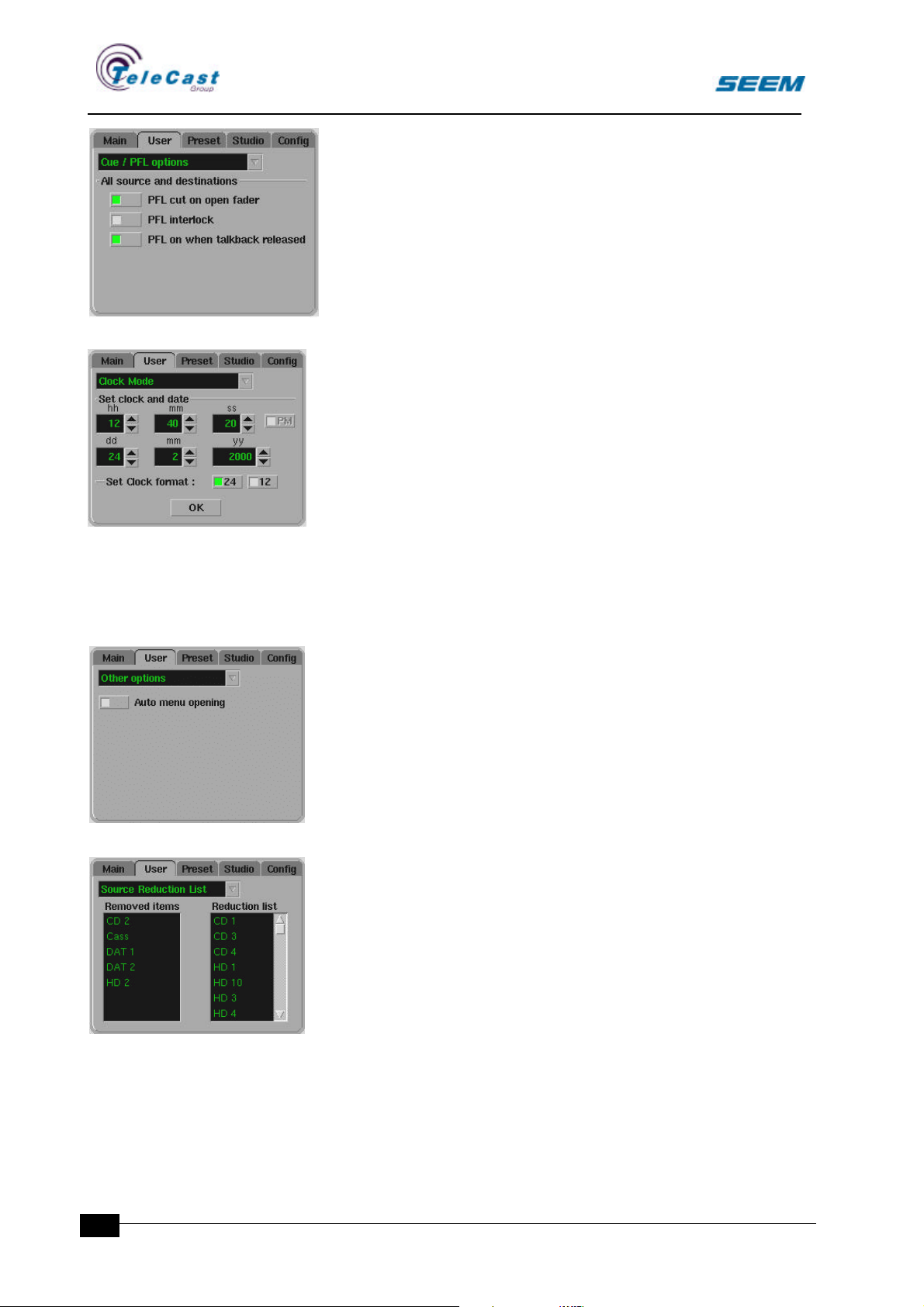
8.1.5 CUE and PFL options
PFL cut on open fader. This option disables the PFL
whenever the channel is on air. When the channel goes off
air the PFL enables again.
PFL interlock. This option gives only one active PFL
channel at any time. Any other channel with active PFL will
be released.
PFL on when talkback is released. This option activates
PFL after every talkback from a CUE switch. In this way
any replies will be received.
8.1.6 Clock mode
The user can select 12 or 24 hour display mode for real
time clock.
8.1.7 User area options
This menu is not yet available.
8.1.8 Other options
Auto menu opening. Enables opening of assign window
menus when related controls are operated.
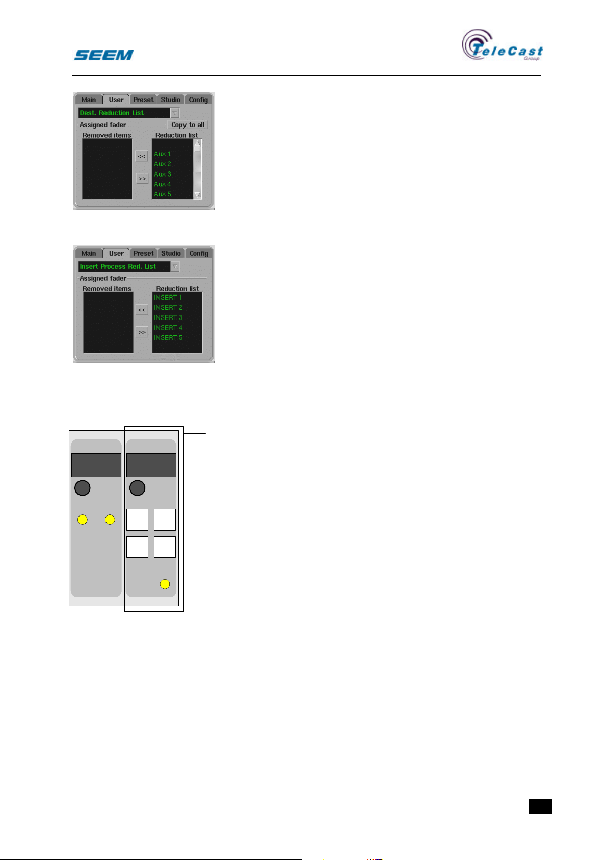
8.1.9 Source reduction list
Every fader position can have a restricted number of
sources available for the input selector.
To select a fader, press an assign button. In the right list all
available sources are shown. By default all sources are
available. Sources can now be dragged to the left list of
removed sources. Sources can later be moved back.
The minimum number of sources is 1 that gives no
selections at all. This can be convenient in a simple set-up
where easy operation is important.
30
seector00.doc 27.04.00
Page 33
SEECTOR User Manual
8.1.10 Destination reduction list
Every fader position can also have a restricted number of
destinations available. The operation is the same as for
source reduction list.
8.1.11 Insert list
Every source and destination can have a reduction list to
remove unwanted insert processes from the insert list.
8.2 User set-up storage
STOPWATCH USER SETUP
00:00:00 USER-001
SELECT
DOWN UP
PRESET
1
PRESET
3
PRESET
LOAD
USER
WRITE
AP4401
2
8.2.1 General
All parameters defined in the user set-up as well as actual settings
of switches and encoders can be stored in snapshot set-ups on a
diskette.
The preset memory panel is used for storing and loading snapshot
settings for the console.
The set-ups are given names in the system preset menu.
8.2.2 Controls
• 8-character display
• Encoder with detents
• Illuminated User preset switch
• Illuminated Preset switch 1 to 3
• Illuminated write switch
The preset selector selects set-ups from the set-up list.
The selected set-up are loaded when the USER PRESET switch is
pressed.
In addition to the selectable user set-ups three basic set-ups are
stored in the user surface independent of the user diskette.
seector00.doc 27.04.00
31
Page 34
SEECTOR User Manual
These are loaded by pressing the PRESET 1, PRESET 2, PRESET 3
switches.
When set-ups shall be stored the WRITE switch is held while the
PRESET switch is pressed. If a name is shown in the user set-up
display this set-up will be overwritten. If the display is blank, a new
set-up is stored with a default name that can be changed in the preset
menu.
Channels that are on air will not be changed until they are closed.
8.2.3 More fixed presets
More presets can be available with an additional switch panel.
These switches are freely programmable, and can be set to wrk as
preset switches.
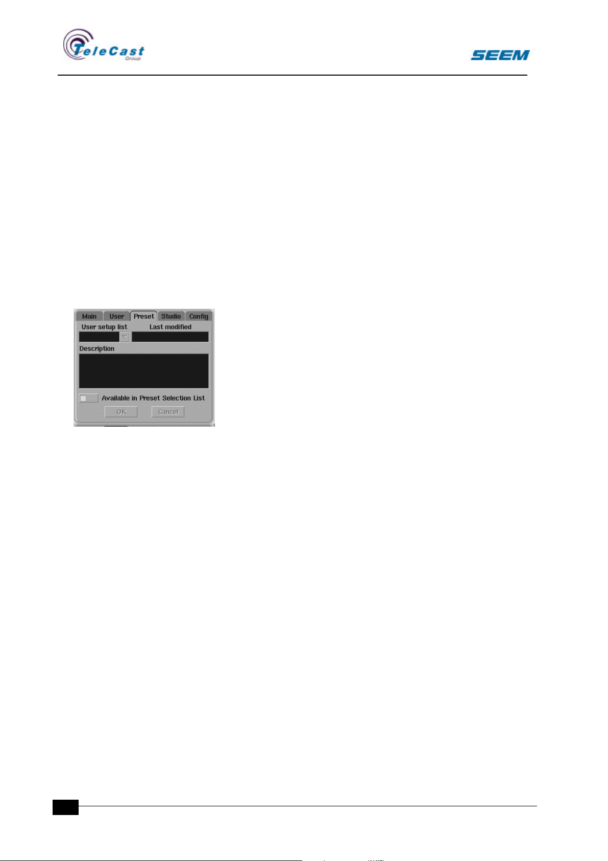
8.2.4 Preset menu
This menu allows the user to name different user set-ups
that are stored.
In the user set-up list a set-up is selected.
The last modified section shows the date and time when the
set-up was last stored to the diskette.
The description section is a text area for typing comments
for easy recognition.
An active marking selects whether the current set-up shall
be available on the preset panel or not.
32
seector00.doc 27.04.00
Page 35

SEECTOR User Manual
9. Signalling
9.1 General
The console offers a wide range of signals for remote control of
machines and controlling OnAir lights. Also external talkback signals
are available.
All signal inputs and outputs are part of the configuration.
The audio rack manual gives details about different remote control
formats available.
9.2 Studio menu
This menu is not yet available.
9.3 Indicators in the status window
There are small labels in the status window indicating special status
is the console.
• SOLO
• Telephone call
seector00.doc 27.04.00
33
Page 36
SEECTOR User Manual
ax
10. Configuration
10.1 General
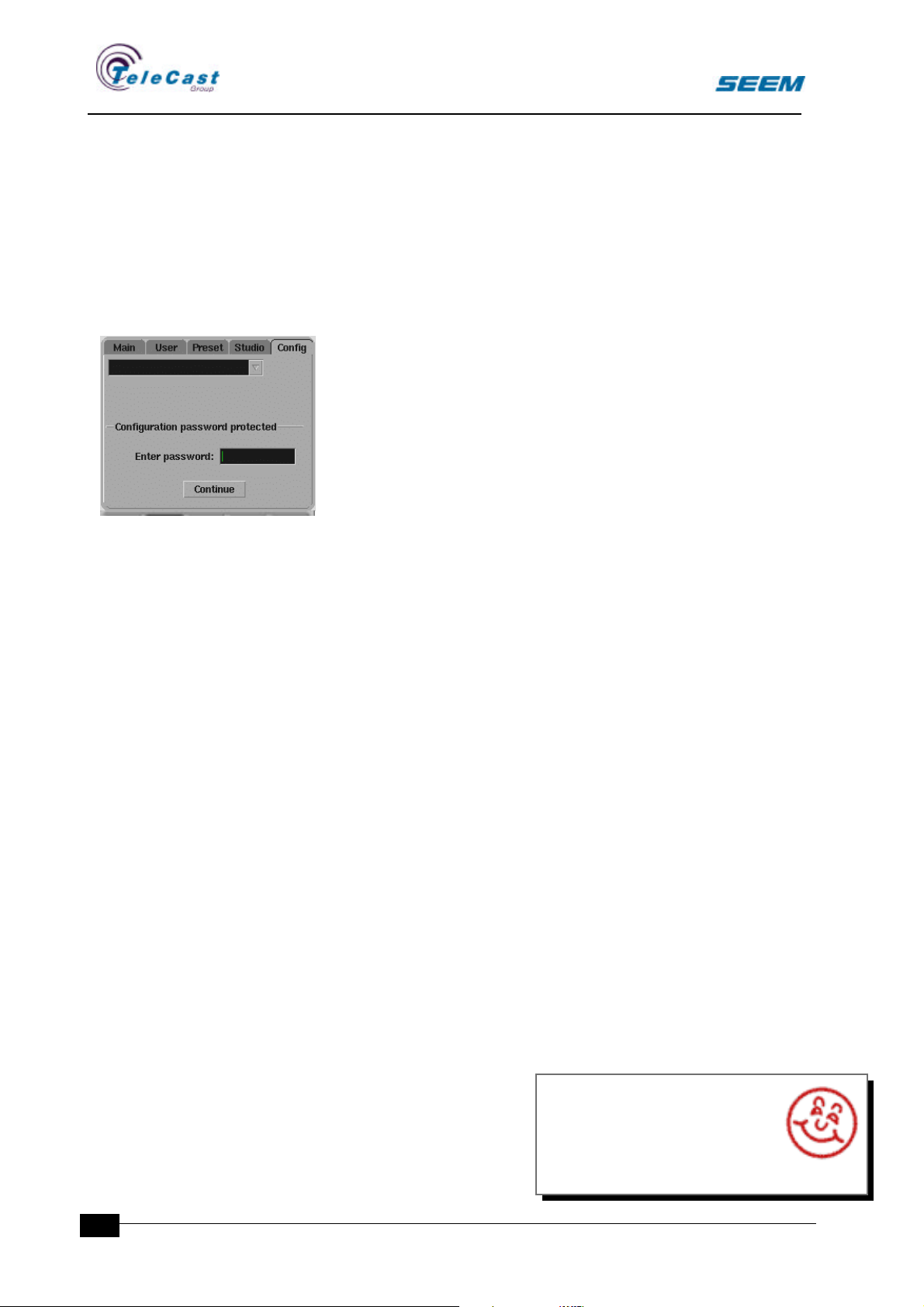
Configurations made in the configuration menu are not part of the
user setups. These settings are of a more fixed nature.
10.1.1 Password
The configuration menu is password protected.
For password please contact system administrator.
34
interstage
Phistersvej 31, 2900 Hellerup, Danmark
Telefon 3946 0000, fax 3946 0040
www.interstage.dk
- pro audio with a smile
seector00.doc 27.04.00
 Loading...