

Page 1
Adder™ AES-8
Digital Audio Multiplexer
Instruction Manual
Telecast Fiber Systems, Inc.
102 Grove Street
Worcester, MA 01605
Tel: 508-754-4858
Fax: 508-752-1520
www.telecast-fiber.com
Page 2

Adder AES-8
ii
Page 3

Table of Contents
Introduction 1
System Components 1
System Features 1
Advantages 1
Applications 2
Theory of operation 2
Power 2
TX Feature Descriptions 4
RX Feature Descriptions 5
Installation 6
Hook-Ups 6
Operation 6
Troubleshooting and Repair 7
Specifications 7
Warranty 8
Telecast Fiber Systems
List of Figures
Adder AES-8 transmission System iv
Mounting Dimensions 3
TX Front and Rear 4
RX front and rear 5
Fiber and Electical hook-Ups 6
iii
Page 4
Adder AES-8
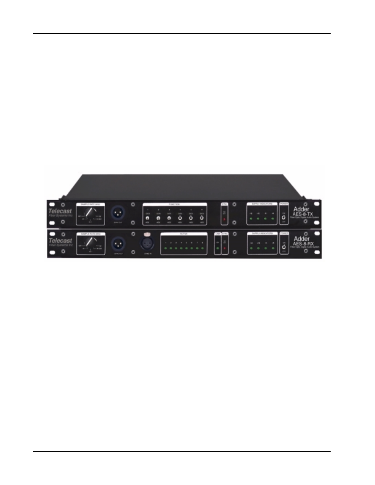
Adder AES-8 Transmitter (Top) and Receiver (bottom)
iv
Page 5

Telecast Fiber Systems
Introduction
The introduction of the Telecast Fiber Systems Adder™ AES/EBU transmission system
marks a new level of modularity and flexibility for the Telecast family of Digital Fiber Optic Snakes. The system multiplexes up to 8 AES/EBU signals and transmits them on
a single optical fiber to a reciever where the signals are restored. This product
complements Telecast’s comprehensive line of audio, video, data and intercom
products and insures that you have digital audio to go with your digital video.
System Components
The Adder AES/EBU system is comprised of a transmitter and a receiver. These units
occupy only a single rack space each and are powered by wall mount power trans
formers. Rack ears and screws are included.
After unpacking, inspect the units for mechanical damage. Also check all electrical
connectors and cables for bent or damages pins. Report any damage to the carrier and
to Telecast Fiber Systems, Inc.
System Features
• Eight stereo AES Digital Audio channels or 16 audio channels
• User-selectable sampling rates of 32, 44.056, 44.1 and 48 KHz
• External synchronization to any valid AES source from 25 to 50 KHz
• All steel construction
Advantages
• Electrical isolation between sites
• Inherent immunity to both EMI and RFI
• No signal degradation
• No ground loops
• Transmission distances up to 5 km with multimode fiber
• High bandwidth allows 8 multiplexed signals to share one fiber reducing the size
and weight of cable system
• Multimode or optional singlemode operation
• Easy installation and field setup
In this manual you will find helpful information about installation, proper use and
features of this product. Please read thoroughly before trying to operate of this
equipment. The information furnished does not include all the details of design or
possible situations that may occur when using this device. For information beyond that
covered in this manual please contact Telecast Fiber Systems, Inc. customer service at
(508)754-4858.
1
Page 6

Adder AES-8
Applications
There are many different applications to which that the Adder AES-8 Transmission
System is suited. Listed below are a few examples.
Broadcast and Video Post-Production
Links among multiple studios
Links between mixing/editing suites
Studio to transmitter links
Recording Studios
Direct-to-digital recording
Digital links between studios
Commercial Installations
Schools and universities
Convention facilities
Post production facilities
Board rooms
Inter-campus linking
Hotel ballrooms and facilities
Theory of Operation
The Adder AES/EBU system consists of an AES-8 Tx transmitter and an AES-8-Rx
receiver. The Tx contains circuitry which can detect a valid AES signal at any of the 8
input channels or sync input and can synchronize to that signal. The AES digital audio
signal is a serial data bit-stream containing two channels of digitized information along
with clocks, flags and user information. Once a signal is received, it derives the sample
rate clock frequency for synchronization of the 8 input channels.
An input FIFO circuit phase-aligns the clock boundaries of the 8 AES inputs to the
synchronization signal, so that all inputs remain perfectly phase-aligned and in sync.
These 8 AES inputs are essentially slots in the high speed multiplexer (MUX) and as
such, the Adder AES-8 System is essentially an AES multiplexer and high speed
fiber-optic transmission system. The serial data rate of the AES MUX is 125Mbit/sec.
The front panels feature SAMPLE RATE switches, active channel LED’s, and
indicators for sync and internal power supplies. The one rack space chassis features
an all steel construction with a tough powder coat finish.
Power
Power to the AES-8 System is supplied by the wall mount transformers included in the
packing. Connect to the power input located on the rear of the units. Power input is
center pin negative at 12V DC at 0.5 Amps.
2
Page 7
14.62”
Telecast Fiber Systems
17.25”
1.75”
19.00”
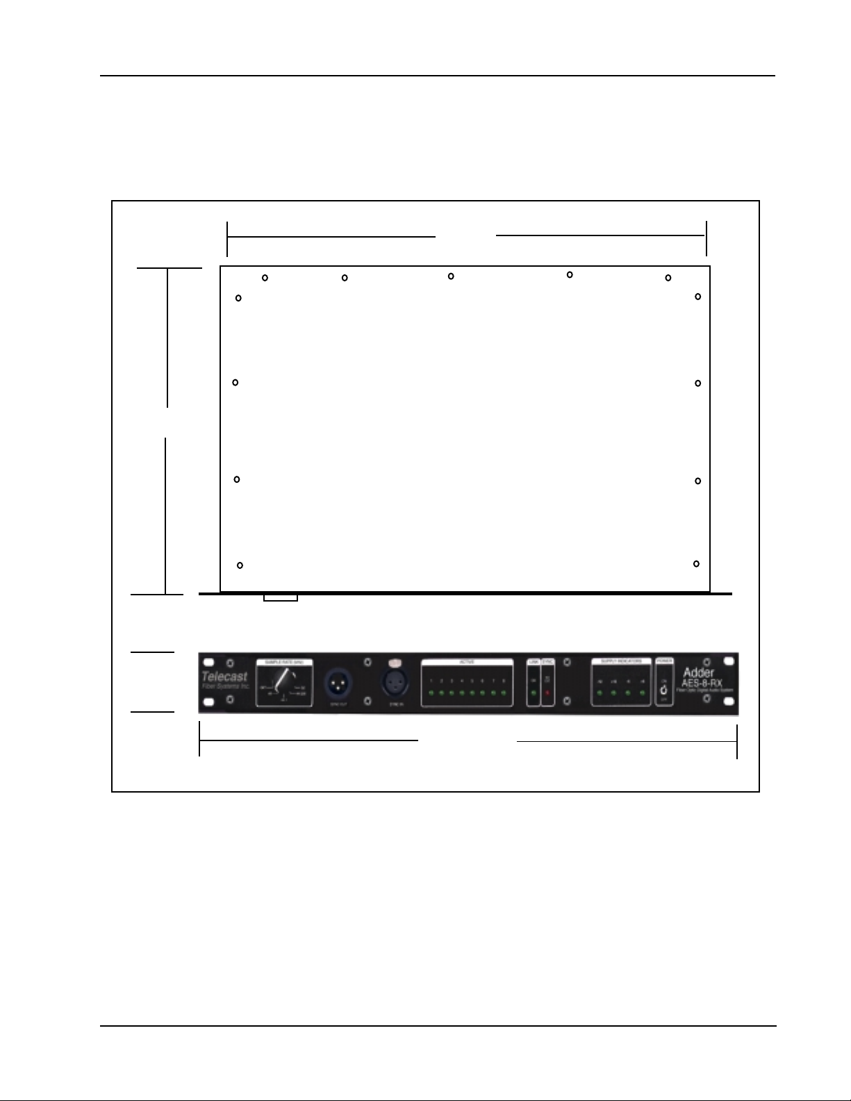
Figure 1. Mounting Dimensions
3
Page 8
Adder AES-8
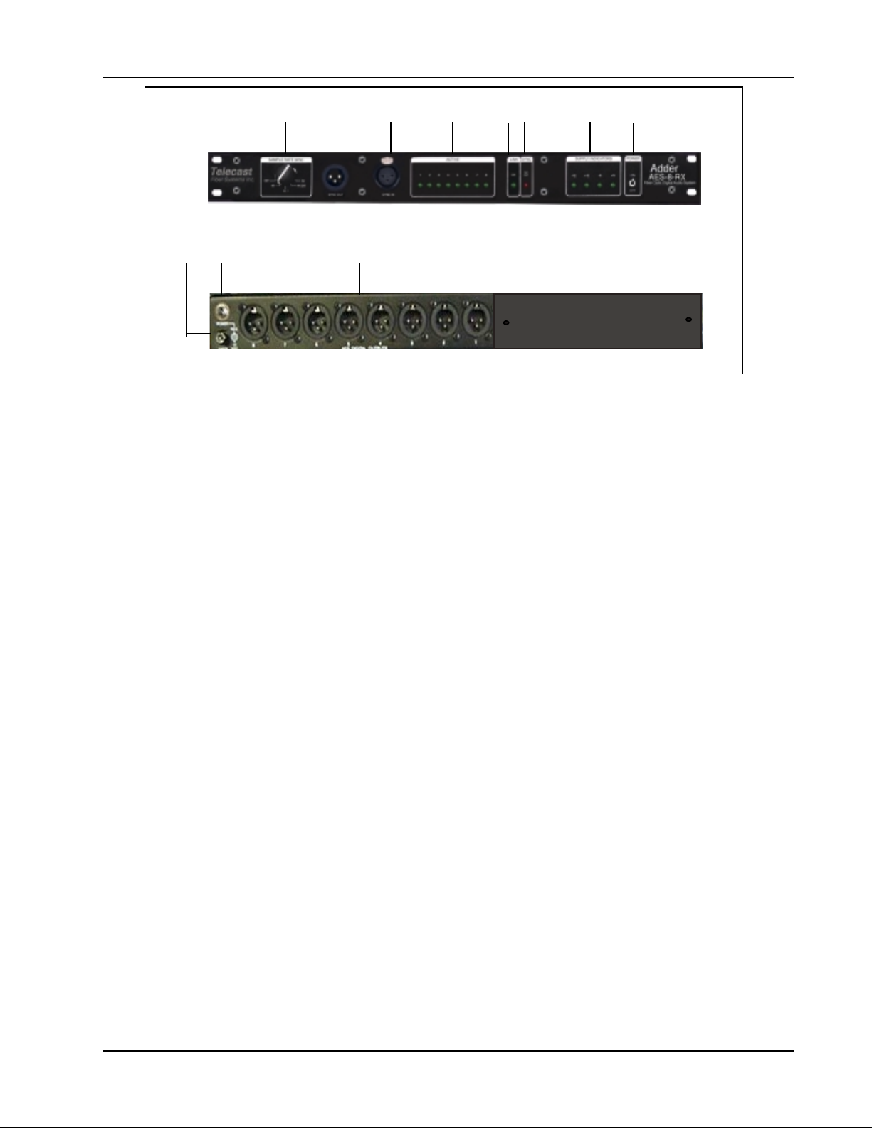
A B C D E F
G H I
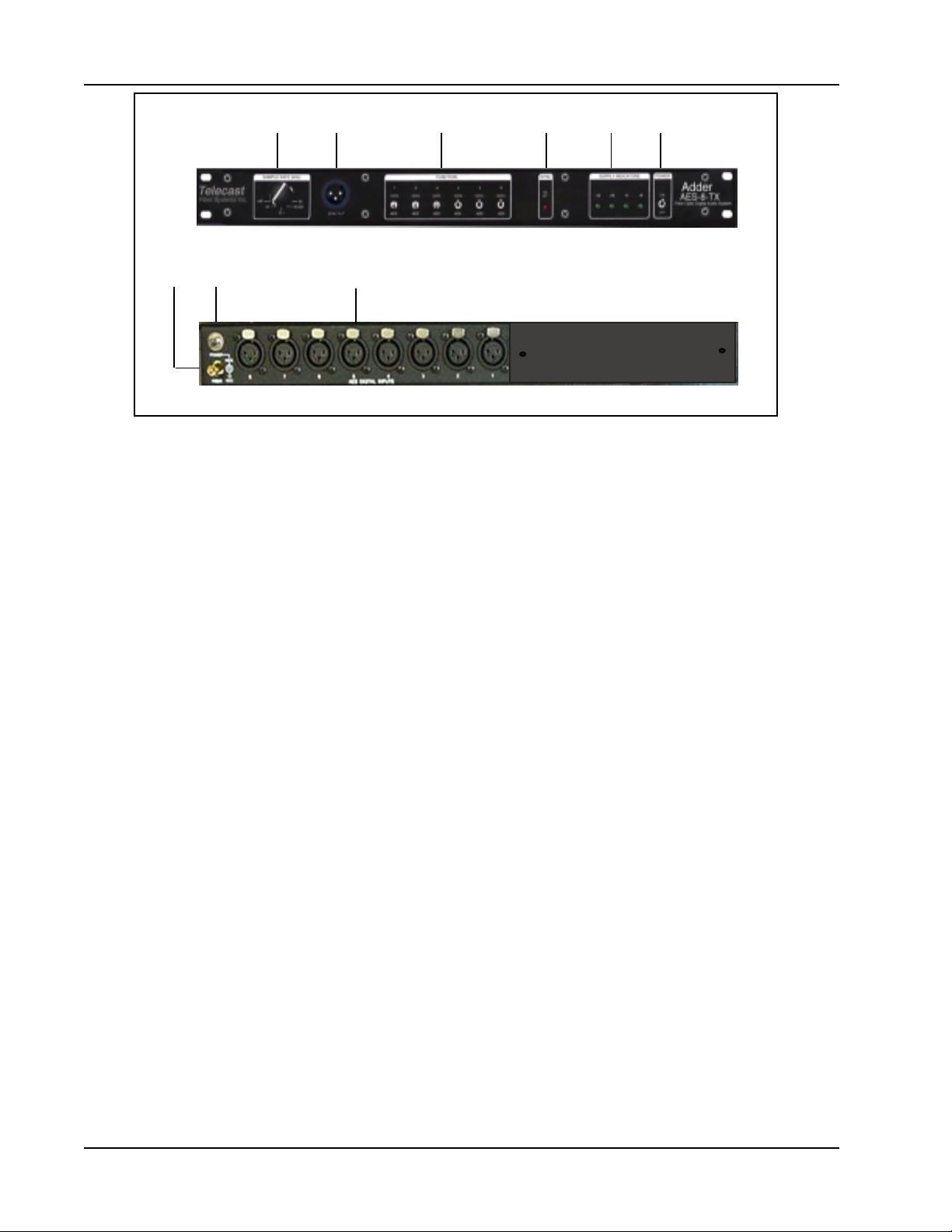
Figure 2. AES-8-Tx Front and Rear Features
AES-8-Tx Features
A. SAMPLE RATE (KHz) Allows the user to select one of four commonly used
sample rates. The sample rates are 48, 44.1, 44.056, 32 and EXT. for an
external sampling rate via. any one of the eight AES Digital Input jacks.
B. SYNC OUT Provides sync signal to an external device. The rate is determined by
the SAMPLE RATE switch selection.
C. FUNCTION Switches offers a selection between AES or Data usage. The Data
functions for the Adder-AES-8 are permanently disabled thus all six switches
should remain in the AES position.
D. SYNC The red LED when lit indicates the unit is not receiving an external sync
signal. Functional only when EXT. is selected for the SAMPLE RATE.
E. SUPPLY INDICATORS Four green LED’s show the status of each internal power
supply, -12, +12, -5, +5.
F. POWER SWITCH Routes power to each of the four internal power supplies.
G. FIBER Fiber-optic output sends optical data down fiber optic cable to the AES-8
Rx receiver unit.
H. POWER INPUT Power receptacle receives 12V DC from wall mount power
transformer or from some other 12V power supply. Receptacle is center pin
negative.
I. AES INPUTS Female XLR connectors provide eight stereo AES Digital Inputs.
4
Page 9
A B C D E F G H
I J K
Figure 3. AES-8-Rx Front and Rear Features
AES-8-Rx Features
Telecast Fiber Systems
A. SAMPLE RATE (KHz) Allows the user to select one of four commonly used
sample rates. The sample rates are 48, 44.1, 44.056, 32 and EXT. for an
external sampling rate via. the SYNC IN jack.
B. SYNC IN Female XLR jack is provided for receiving external sampling rates.
C. SYNC OUT Provides sync signal to other equipment. The rate is determined by
the SAMPLING RATE switch selection.
D. ACTIVE A signal activity LED for each of the eight channels.
E. LINK Green LED indicates fiber integrity is good.
F. SYNC The red LED when lit indicates the unit is not receiving the external sync
signal. This indicator is used when EXT. is selected for the SAMPLING RATE.
G. SUPPLY INDICATORS Four green LED’s show the status of each internal power
supply, -12, +12, -5, +5
H. POWER SWITCH Routes power to each of the four internal power supplies.
I. FIBER Fiber-optic input receives optical data from the AES-8 Tx transmitter unit.
J. POWER INPUT Power receptacle receives 12V DC from a wall mount transformer
or from any 12V power supply. Receptacle is center pin negative.
K. AES OUTPUTS Male XLR connectors provide eight stereo AES Digital Outputs.
5
Page 10
Adder AES-8
Installation
The Adder AES-8 Transmission System was designed to mount in a standard 19" rack.
When mounting inside an enclosed rack make sure there is adequate ventilation. You
should avoid placement next to excessive heat sources such as power amplifiers or
heaters. In portable installations where subject to severe mechanical shock, secure the
rear of the units.
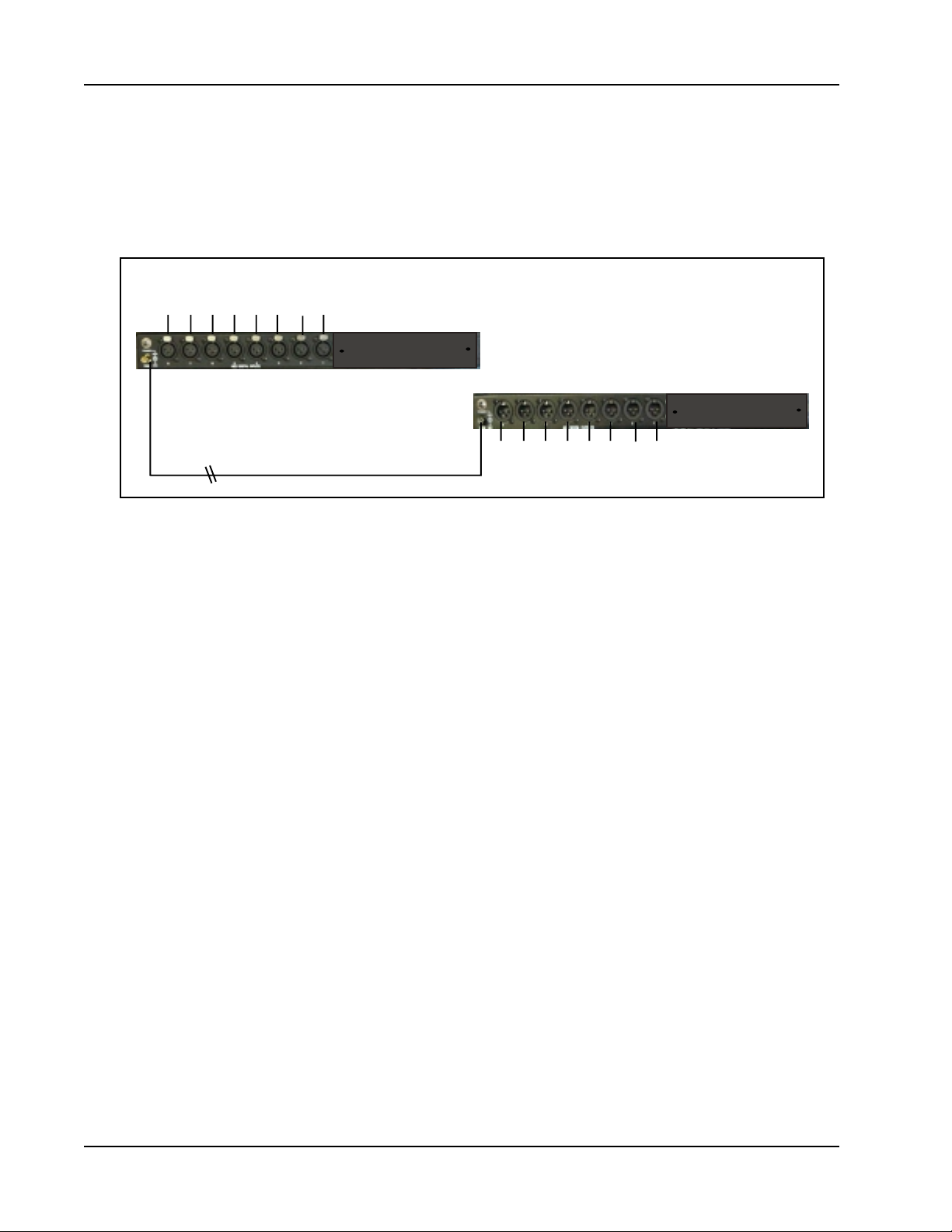
XLR Cables from AES
Digital Audio Source
Fiber Optic Cable
Figure 4 . Digital Audio Hookup Diagram
XLR Cables to AES
Digital Audio Devices
Hookups
Once the AES-8 units are installed you are ready for the fiber-optic connection. Attach
the fiber-optic cable to each of the AES-8 units at the FIBER connector. The optical
transmitter and receiver require 62.5/125m multimode fiber-optic cable with ST
terminations. For field applications, secure it first by loosely tying off to the rack or a
nearby anchor point. Special singlemode units require 8/125 micron cable with ST
connectors.
If you are using multi-core fiber-optic cable with your system, the individual fiber lines
will be color coor-dinated or numbered to help you identify each separate fiber line.
Now connect all the AES digital audio inputs and outputs. An example of these
hookups are demonstrated above in figure 4, Digital Audio Hook-up Diagram.
Operation
Before power-up, configure the AES-8 units for use. At the Tx unit, the SAMPLE RATE
switch should be set to EXT. for external sync. The AES-8 will then detect and
synchronize to the first valid AES input signal of the eight AES Digital inputs. For the
Rx unit, the SAMPLE RATE switch can be set to the known sample rate frequency or a
sync signal can be brought in at the SYNC IN and the SAMPLE RATE switch set to
EXT. This is the typical configuration when using the AES-8 to transmit AES Digital
Audio signals as demonstrated in the diagram above. The system can now be powered
starting with the appliances preceding the AES-8, then the Tx and Rx units, and finally
the equipment following. The units should immediately process signal unless
configured or hooked-up improperly.
6
Page 11

Telecast Fiber Systems
In the unique case where you have a AES Digital signal with a unknown frequency, set
the SAMPLE RATE switch for the Tx to EXT., at the Rx simply step through each of the
sample rate choices. If none of the four choices work, then an external sync signal will
have to be provided at the Rx unit.
Troubleshooting and Repair
The Adder AES-8 system is “plug and play”. There are no use adjustments inside nor
are there any user serviceable parts inside. Assuming the units have power
indications, operation is immediate following the presentation of a valid AES signal. If
any problems arise that can not be solved using this manual, contact Telecast.
Call Telecast Fiber Systems, Inc. for assistance with the Adder 161 System at
508-754-4858 and ask for our service department. To return a unit for repair, you must
obtain a return material authorization (RMA) number from Telecast service.
Specifications
Electrical Specifications
Sample rates Selectable for 32KHz, 44.056KHz,
44.1KHz, 48KHz, or external sync
Inputs 8 channels (XLR female conn.)
Outputs 8 channels (XLR male conn.)
Input/output format AES/EBU digital audio
(complies with full implementation of the AES 3spec.)
AES sync input/output XLR connectors
Input power 12V DC at .5 Amps,
center pin negative
Supply indicators Green LED’s, -12,+12,-5,+5V DC
Optical Specifications
Transmission distance Up to 20km
Wavelength 1310nm Multimode or Singlemode
Tx optical output (Avg.) 0 dBm
Rx optical input Sensitivity (Avg.) -30 dBm
Optical power budget Up to 30 dBm
Physical
Dimensions 1.75"H x 19"W x 14.75"D
Shipping weight 11 lbs.
*** Note that in cases of short fiber lengths or runs of very little optical loss,
an optical attenuator of at least 15dBm may be needed to reduce the
potential of overloading the receiver.
7
Page 12

Adder AES-8
Warranty
LIMITED WARRANTY STATEMENT
Telecast Fiber Systems, Inc. (“Telecast”) expressly warrants to Buyer that the Products supplied shall be free
from defects in materials and workmanship for a period of 12 months following the date the Products are delivered to Buyer (the “Warranty Period”). Telecast's liability under this limited warranty shall be limited, at its option,
to providing refund of purchase price for Products, or replacing or repairing Products shown to be defective
either in materials or workmanship. Buyer's sole and exclusive remedy for breach of warranty shall be such
refund, replacement or repair.
A claim of defect in materials or workmanship in any Product shall be allowed only when it is submitted in writing
to Telecast Fiber Systems, Inc. within seven days after discovery of the defect, and in any event within the
Warranty Period. No claim shall be allowed in respect of any Product which has been altered, neglected, damaged or stored in any manner which adversely affects it. In order to obtain service under the terms of this
warranty, Distributor’s customer or Distributor must notify Telecast of the defect prior to the expiration of the
applicable warranty period and obtain a Return Authorization Number from Telecast. In no event may products be
returned to Telecast or to Distributor for warranty service without having obtained from Telecast a Return Authorization Number.
This limited warranty applies only to new and unused Products delivered to Buyers located within the United
States of America, or to international Buyers if sold through an authorized Distributor organization, and shall not
extend to any equipment not manufactured by Telecast Fiber Systems, Inc., even though such equipment may be
sold or operated with the Products. In addition, this limited warranty shall be void and of no further force or effect
whatsoever if the Product is repaired or modified by any person other than an authorized representative of
Telecast Fiber Systems, Inc. without the consent of Telecast Fiber Systems, Inc. This warranty shall not apply to
any defect, failure or damage caused by improper use or inadequate maintenance and care. Nor shall this
warranty apply to any damage caused in whole or in part by attempts by personnel other than Telecast’s personnel, as approved in advance in accordance with the foregoing provisions, to open, install, repair, or service the
Product; nor to damage resulting from improper connection with incompatible equipment; nor to damage to a
unit which has been modified by personnel other than Telecast personnel.
Products returned to Telecast for warranty service shall be shipped, freight prepaid to Telecast. Telecast will
return the repaired product or ship a replacement, freight prepaid, to either Distributor or Distributor’s customer,
as requested by Distributor’s customer, at a location within the United States or, at Telecast’s option, to
Distributor’s location in the case of international sales.
This limited warranty shall also apply to Products that replace defective Products and Products that have been
repaired by authorized representatives of Telecast Fiber Systems, Inc., but only for the original Warranty Period.
The Warranty Period shall not be extended by reason of defect, or any period of time during which the Product is
not available to Buyer because of defects or repairs, without the express written consent of Telecast Fiber
Systems, Inc.
EXCEPT FOR THE EXPRESS LIMITED WARRANTY AGAINST DEFECTS IN MATERIALS AND WORKMANSHIP
CONTAINED HEREIN, TELECAST FIBER SYSTEMS, INC. MAKES NO WARRANTY OF ANY KIND WHATSOEVER,
EXPRESS OR IMPLIED, AND ALL WARRANTIES OF MERCHANTABILITY, FITNESS FOR A PARTICULAR PURPOSE, AND OTHER WARRANTIES OF WHATEVER KIND ARE HEREBY DISCLAIMED BY TELECAST FIBER
SYSTEMS, INC. THIS LIMITED WARRANTY SETS FORTH EXCLUSIVELY ALL OF TELECAST FIBER SYSTEMS,
INC.'S LIABILITY IN CONTRACT OR OTHERWISE IN THE EVENT OF A DEFECTIVE PRODUCT.
WITHOUT LIMITATION ON THE FOREGOING, TELECAST FIBER SYSTEMS, INC. EXPRESSLY DISCLAIMS ANY
LIABILITY WHATSOEVER FOR ANY DAMAGES INCURRED DIRECTLY OR INDIRECTLY IN CONNECTION WITH
THE SALE OR USE OF, OR OTHERWISE IN CONNECTION WITH, THE PRODUCT, INCLUDING WITHOUT LIMITATION, LOSS OF PROFITS AND SPECIAL, INCIDENTAL OR CONSEQUENTIAL DAMAGES, WHETHER CAUSED BY
NEGLIGENCE OR OTHERWISE, REGARDLESS WHETHER TELECAST HAS BEEN GIVEN ADVANCE NOTICE OF
THE POSSIBILITY THEREOF.
THIS WARRANTY IS GIVEN BY TELECAST IN LIEU OF ANY OTHER WARRANTY EXPRESSED OR IMPLIED.
8
 Loading...