

Page 1

ä
Adder
882 System
Instruction Manual
Telecast Fiber Systems, Inc.
102 Grove Street
Worcester, MA 01605
Tel: 508-754-4858
Fax: 508-752-1520
www.telecast-Þber.com
Page 2

Adder 882
ii 1 April 1999
Page 3

Telecast
Table of Contents
Introduction .................................................................................................................................1
Unpacking ....................................................................................................................................2
Installation ...................................................................................................................................3
Rack Mounted Installation ...........................................................................................................3
Fiber Optic Installation ................................................................................................................3
Audio Setup .................................................................................................................................4
Procedure .....................................................................................................................................4
Optical Connections ....................................................................................................................6
Electrical Connections .................................................................................................................6
Input Power Fuse .........................................................................................................................8
Operating Details .........................................................................................................................9
Battery Charging ..........................................................................................................................9
Powering Up ................................................................................................................................9
Theory of Operation ..................................................................................................................10
Digital I/O ..................................................................................................................................12
Optical .......................................................................................................................................15
Preventive Maintenance ............................................................................................................16
Accessory List ...........................................................................................................................16
Troubleshooting .........................................................................................................................16
Specifications .............................................................................................................................18
Warranty ....................................................................................................................................20
Table of Contents iii
Page 4

Adder 882
iv 1 April 1999
Page 5

List of Figures
Figure 1. Rear Panel of the Adder 882.........................................................................................1
Figure 2. Block Diagram of a One Fiber System.........................................................................2
Figure 3. Possible Optical Configurations ...................................................................................2
Figure 4. Installing the Rack Mount Adapters .............................................................................3
Figure 5. Audio Setup Controls....................................................................................................5
Figure 6. Main Circuit Board .......................................................................................................5
Figure 7. ST Optical Connectors on the Rear Panel.....................................................................6
Figure 8. XLR Connectors on the Rear Panel..............................................................................7
Figure 9. RS-422 D Connectors on the Rear Panel......................................................................8
Figure 10. Power Connector and Fuse Locations...........................................................................8
Figure 11. Front Panel....................................................................................................................9
Figure 12. Electronics Block Diagram.........................................................................................10
Figure 13. Audio Input Buffer Circuit..........................................................................................11
Figure 14. Audio Output Buffer Circuit.......................................................................................11
Figure 15. Digital I/O Connectors 1, 3, 5 and 7 ...........................................................................13
Figure 16. Digital I/O Connectors 2, 4, 6 and 8 ...........................................................................14
Figure 17. Battery Charger Block Diagram .................................................................................15
Telecast
List of Tables
Table 1. Maximum Fiber Lengths............................................................................................... 3
Table 2. Audio Inputs.................................................................................................................. 4
Table 3. Input and Output Cable Connections............................................................................ 6
Table 4. Digital Cable Connections ............................................................................................ 7
Table 5. Power Connections ....................................................................................................... 8
Table 6. Adder 882 Main Circuits ............................................................................................ 17
Table 7. Troubleshooting Chart ................................................................................................ 18
List of Figures v
Page 6

Adder 882
vi 1 April199
Page 7
Introduction
The Telecast Adder
multiplexer/demultiplexers that simultaneously send and receive up to eight audio signals, eight
digital datas, and four remote relay closures in each direction. These signals are transmitted on
optical Þbers. Audio inputs are set up by internal DIP switches that set ampliÞer gain to accept
either mic or
RS-422 and RS-232 compatible signals. Four of the digital connectors also provide contact
closure input and output. The other four connectors alternatively provide SONY CCU compatible
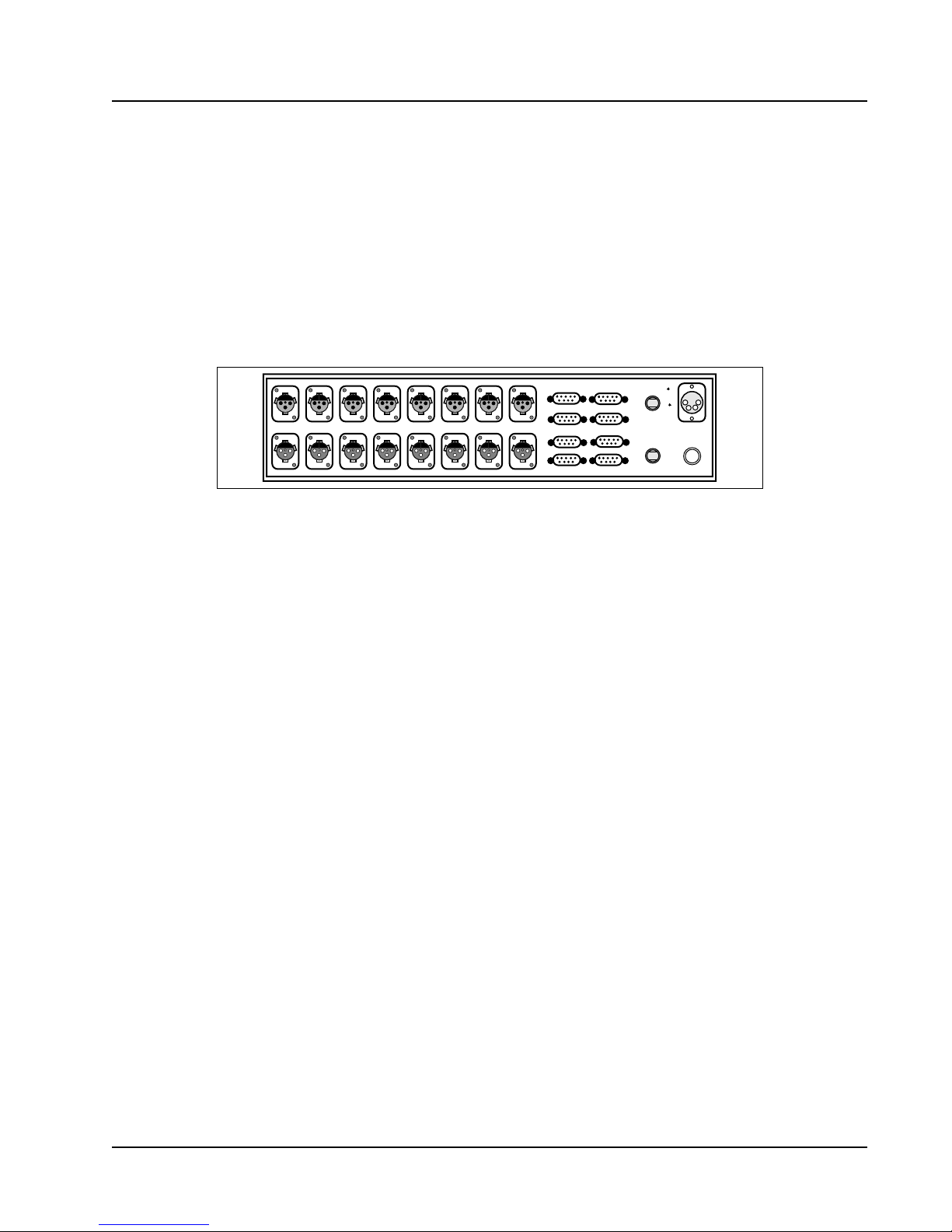
interfaces. All connections are made via the rear panel. See Figure 1.
TM
882 System consists of two Adder 882 Þber optic
line levels. Audio outputs are always at line levels. Digital inputs and outputs are
Telecast
AUDIO IN 1
AUDIO OUT 1
AUDIO IN 2
AUDIO OUT 2
AUDIO IN 3
AUDIO OUT 3
AUDIO IN 4
AUDIO OUT 4
AUDIO IN 5
AUDIO OUT 5
AUDIO IN 6
AUDIO OUT 6
AUDIO IN 7
AUDIO OUT 7
AUDIO IN 8
AUDIO OUT 8
1
3
DATA I/O
5
7
2
A(Tx)
4
OPTICAL I/O
6
B(Rx)
8
DC INPUT
12-24VDC
2AMP, SLO BLO
Figure 1. Rear Panel of the Adder 882
Within an Adder 882 unit, the audio signals are Þrst digitized and then multiplexed with the
digital data and control signals. The combined electrical signal is converted to an optical signal,
launched into the optical Þber and sent to a second Adder 882. This second unit receives the
optical signal, converts it into an electrical data stream, demultiplexes the signals and restores the
audio signals to analog levels.
An internal Ni-Cad battery provides backup in the event of line power loss.
The Adder 882 is available with several optical options and conÞgurations.
¥ Standard connection with bidirectional signals carried on two optical Þbers at either 850, 1300,
or 1550 nm.
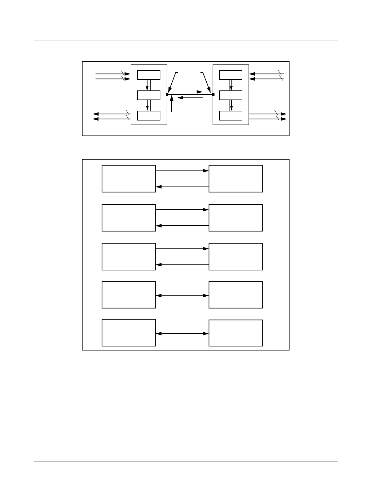
¥ One Þber connection with optically combined bidirectional signals at 850/1300 nm or
1300/1550 nm as shown in Figure 2.
In a standard two Þber system, identical Adder 882 units are used at each location. The units both
transmit at 850 nm on ST connector
and receive the 850 nm signal on ST connector
B
. They are
A
connected by the two Þbers so that the optical output of each box is connected to the optical input
of the other. In both one and two Þber systems, the input of channel 1 on one unit becomes the
output of channel 1 on the other unit, and vice versa.
In a one Þber system, the two Adder 882 units are
not identical and are conÞgured before
shipment. They must be used as a pair. The units are connected by a single Þber that is wavelength
A
division multiplexed (WDM). One unit transmits from the
1300 nm and also receives at 850 nm on the same connector. The other unit transmits from the
ST connector at a wavelength of
A
ST connector at 850 nm and similarly receives at 1300 nm on the same connector.
Figure 3 illustrates available optical conÞgurations of the ADDER 882.
Introduction 1
Page 8
Adder 882
8 Audio in
8 Digital in (RS-422)
LED
850 nm
WDM
1300 nm
8 Audio out
DET
8 Digital out (RS-422)
Unit A Unit B
ST type
connector
850 nm
1300 nm
Single Optical
Fiber
LED
WDM
DET
Digital in (RS-422) 8
1300 nm
850 nm
Digital out (RS-422)
Figure 2. Block Diagram of a One Fiber System
TX 850 nm
Unit A Unit B
RX 850 nm
TX 1300 nm
Unit A Unit B
RX 1300 nm
TX 1550 nm
Unit A Unit B
RX 1550 nm
850 nm
850 nm
1300 nm
1300 nm
1550 nm
1550 nm
RX 850 nm
TX 850 nm
RX 1300 nm
TX 1300 nm
RX 1550 nm
TX 1550 nm
Audio in 8
Audio out 8
8
TX 850 nm
Unit A Unit B
RX 1300 nm
850 nm
1300 nm
TX 1300 nm
Unit A
RX 1550 nm
1300 nm
1550 nm
RX 850 nm
TX 1300 nm
RX 1300 nm
Unit B
TX 1550 nm
Figure 3. Possible Optical ConÞgurations
Unpacking
The Adder 882 System consists of:
¥ Two Adder 882 multiplexer/demultiplexer units
¥ Two external power supplies (AC/DC adapters)
¥ Rack mount hardware kits
¥ Plastic or metal covers for optical connectors
2 1 April 1999
Page 9
Installation
Inspect the units for mechanical damage. Inspect all electrical connectors for bent or damaged
pins and latches. Report any damage to the carrier and to Telecast Fiber Systems, Inc.
Leave the protective plastic caps on the optical connectors until it is time to attach the Þber(s) to
the units. Store the caps in the plastic bag packed with this manual. Place the caps back on the
connectors whenever the Þbers are left disconnected.
Rack Mounted Installation
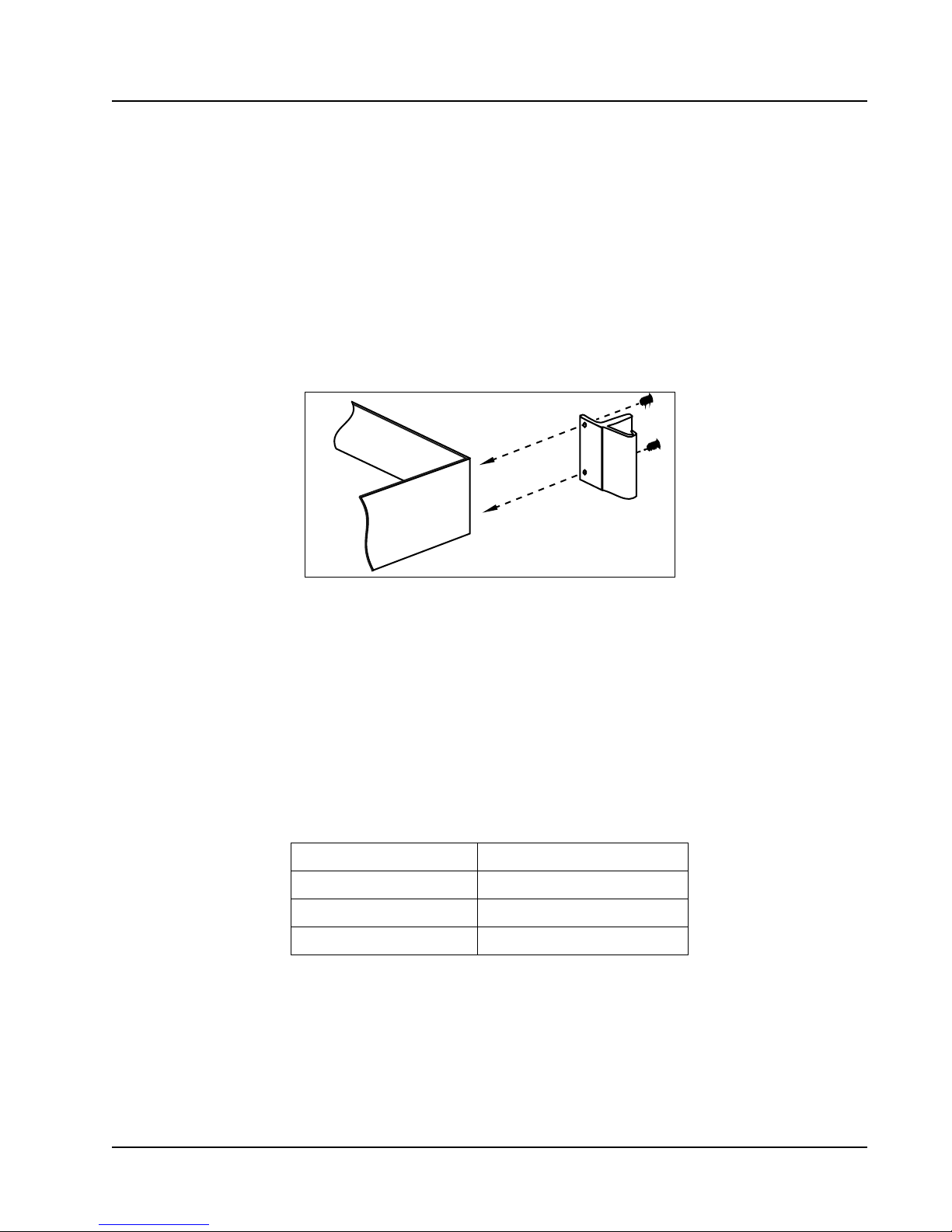
Units are shipped ready for bench use. To rack mount the units, mounting adapters must be
attached. Each adapter is held in place by two #10 ßat head screws (see Figure 4).
Telecast
ä
ADDER 882
AUDIO/DATA MUX/DEMUX
TELECAST
FIBER SYSTEMS, Inc.
Made in the USA
Figure 4. Installing the Rack Mount Adapters
Place the units in their intended locations before attaching any cables or wires. This will prevent
accidental damage to the cables or their connectors.
Fiber Optic Installation
The installer is responsible for providing the Þber optic cable runs which are available from
Telecast Fiber Systems, Inc. Refer to the Accessory List on page 16 of this manual for the cable
and other items required for system installation. Be sure that the Þber core diameters are
compatible with the intended installation distances as shown in Table 1.
Table 1. Maximum Fiber Lengths
Fiber core diameter Maximum Þber length
50 microns 5 km (3 mi)
62.5 microns 3 km (2 mi)
8 microns (single mode) 10 km (6 mi)
The system units have been conÞgured at the factory for the Þber type with which they are going
to be used.
Mark or tag the optical Þbers when they are pulled, carefully avoiding the Þber tip, so that their
identity is known at both ends. If there is confusion about the identity of the two Þbers, illuminate
the end of one Þber with a ßashlight and look for the light at the other end.
Installation 3
Page 10

W
Adder 882
WARNING Do NOT use the Adder 882 optical output for this purpose. Never look
directly into the end of the optical Þber while either end of the system is
operating. Eye damage is possible.
Inspect the Þber ends and clean them with clean, dry compressed air or with Kim-Wipes that have
been wet with isopropyl alcohol. Fingerprints or other dirt on the optical connector end surfaces
will reduce the received optical signal level.
Audio Setup
The setup switches for line or microphone inputs levels are inside the Adder 882. Setup steps are
required if all inputs are at the factory default 600 W, 0 dB gain, line level. Setup is required if
not
microphone inputs are used, if 5 k
boost/cut is desired on line inputs.
Procedure
1. Determine which inputs will be connected to microphones and for which line I/O the 10 dB
boost/cut is to be used.
input impedance is required, or if the optional 10 dB
2. Copy Table 2 and Þll in the required I/O characteristics. Recopy the original table for use with
other hookups.
With the power switch off , take off the top cover of the unit by removing the #4 ßat head screw
3.
at each corner.
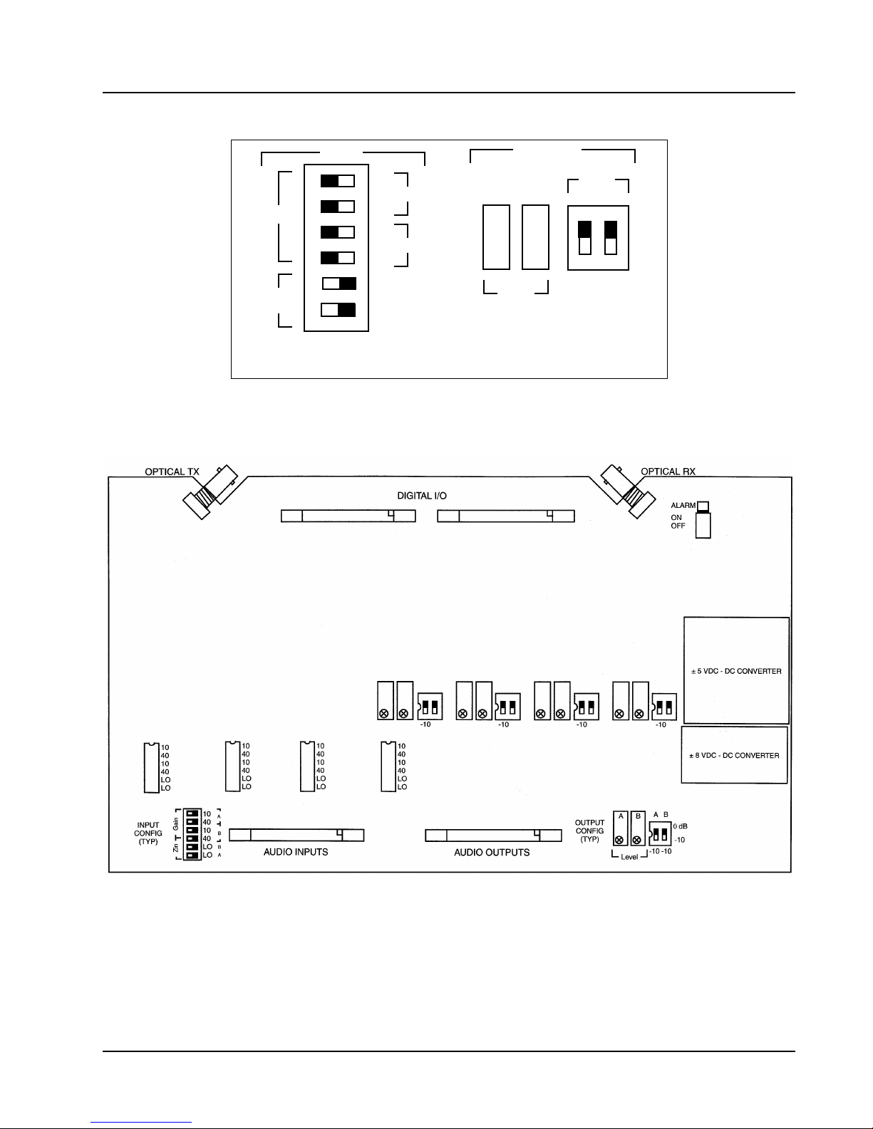
In Figure 5,
A
refers to the odd numbered channel and
B
refers to the even numbered channel of
the pair.
Table 2. Audio Inputs
Channel Number
UNIT A SWITCH SETTING 12345678
MIC IN (0 or +40 db gain)
LINE IN (0 or +10 db gain)
INPUT IMPEDANCE (600 W or 5 k W )
LINE OUT (0 or - 10 db gain)
UNIT B SWITCH SETTING 12345678
MIC IN (0 or +40 db gain)
LINE IN (0 or +10 db gain)
INPUT IMPEDANCE (600 W or 5 k W )
LINE OUT (0 or - 10 db gain)
4. With the rear of the unit facing you (connector end), move the slide switches shown in
Figures 5 and 6 to match the settings in Table 2. The controls are arranged in pairs.
4 1 April 1999
Page 11
Telecast
Input
10
B
Gain
40
10
A
40
B
Z
in
Switches are shown in the factory default position.
Inputs @ 600 W, unity gain. Outputs @ unity gain.
Lo
Lo
A
Figure 5. Audio Setup Controls
5. Replace the top cover and gently reinstall the screws.
Ä
Fine
Level
Output
Gain
Ä
-10 -10
ABAB
Installation 5
Figure 6. Main Circuit Board
Page 12
Adder 882
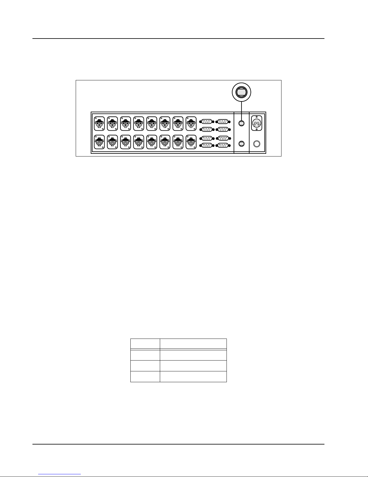
Optical Connections
Refer to Figure 7 before beginning the optical connections.
AUDIO IN 1
AUDIO OUT 1
AUDIO IN 2
AUDIO OUT 2
AUDIO IN 3
AUDIO OUT 3
AUDIO IN 4
AUDIO OUT 4
AUDIO IN 5
AUDIO OUT 5
AUDIO IN 6
AUDIO OUT 6
AUDIO IN 7
AUDIO OUT 7
AUDIO IN 8
AUDIO OUT 8
1
3
DATA I/O
5
7
2
4
6
8
A (TX)
OPTICAL I/O
B (RX)
DC INPUT
12-24VDC
2AMP, SLO BLO
Figure 7. ST Optical Connectors on the Rear Panel
WARNING Never look directly into the end of the optical Þber while either end of the
system is operating. Eye damage is possible.
The Adder 882 is compatible with industry standard ST type connectors. It may be used with
installed backbone cables or with dedicated cables.
Assembled cables and connectors are available from Telecast Fiber Systems, Inc. For custom
cable fabrication, use type ST connectors such as Telecast part number CONN-ST-QC.
Always follow the connector manufacturerÕs directions when fastening a connector to the cable. A
Quick-crimp kit, part number CKIT-ST-QC, is available from Telecast.
A
On a two Þber system, connect the cables so that transmitter ST
B at the other end.
ST
On a one Þber system, connect the Þber optic cable to the ST
at one end connects to receiver
A at each end.
Electrical Connections
Audio
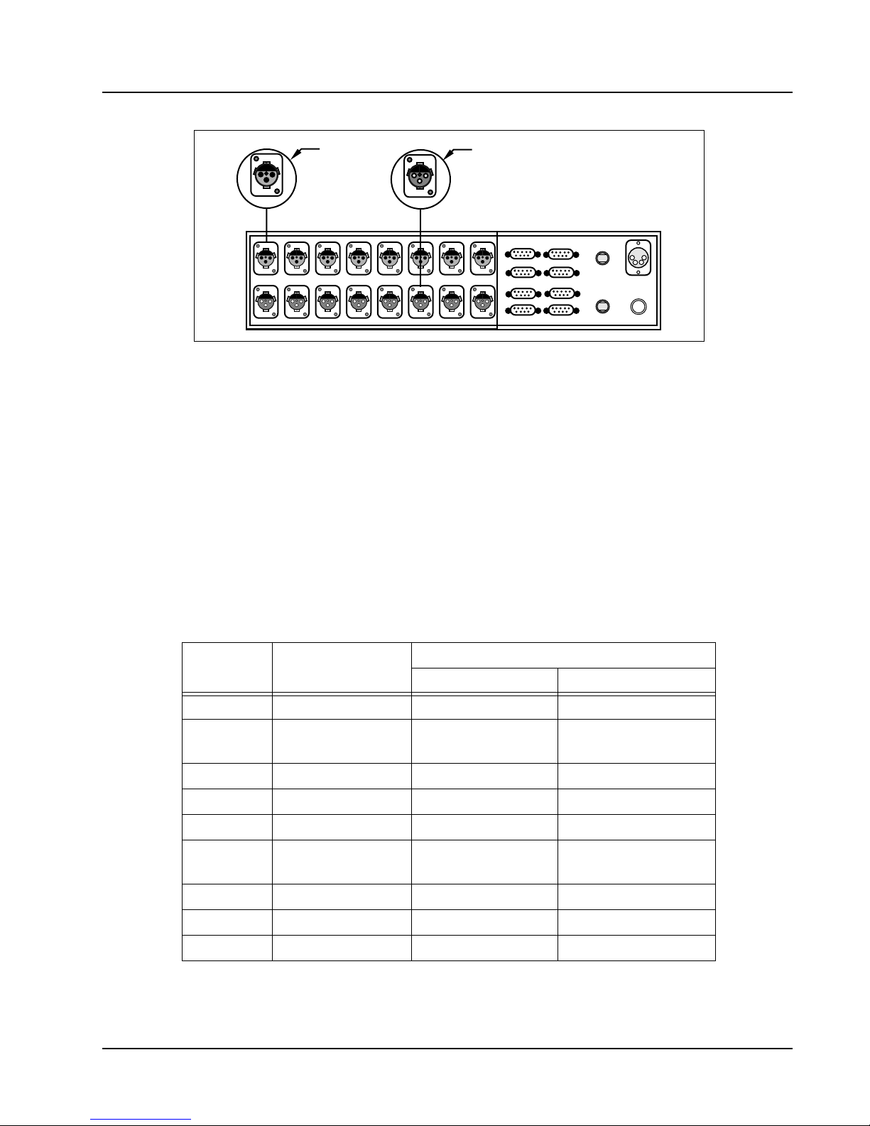
Input and output audio connections use 3-pin XLR connectors with industry standard wire
locations. Table 3 and Figure 8 show these connections.
Table 3. Input and Output Cable Connections
6 1 April 1999
Pin Signal
1 Ground
2 Balanced I/O (-)
3 Balanced I/O (+)
Page 13
Telecast
1
3
AUDIO IN 1
AUDIO OUT 1
2
AUDIO IN 2
AUDIO OUT 2
Female XLR
AUDIO IN 3
AUDIO IN 4
AUDIO OUT 3
AUDIO OUT 4
AUDIO IN 5
AUDIO OUT 5
2
3
AUDIO IN 6
AUDIO OUT 6
1
AUDIO IN 7
AUDIO OUT 7
Male XLR
1
3
AUDIO IN 8
AUDIO OUT 8
5
7
DATA I/O
2
A (Tx)
4
OPTICAL I/O
6
B (Rx)
8
DC INPUT
12-24VDC
2AMP, SLO BLO
Figure 8. XLR Connectors on the Rear Panel
The audio input connector is Switchcraft E3FST-AU. The audio output connector is Switchcraft
E3MST-AU.
Digital
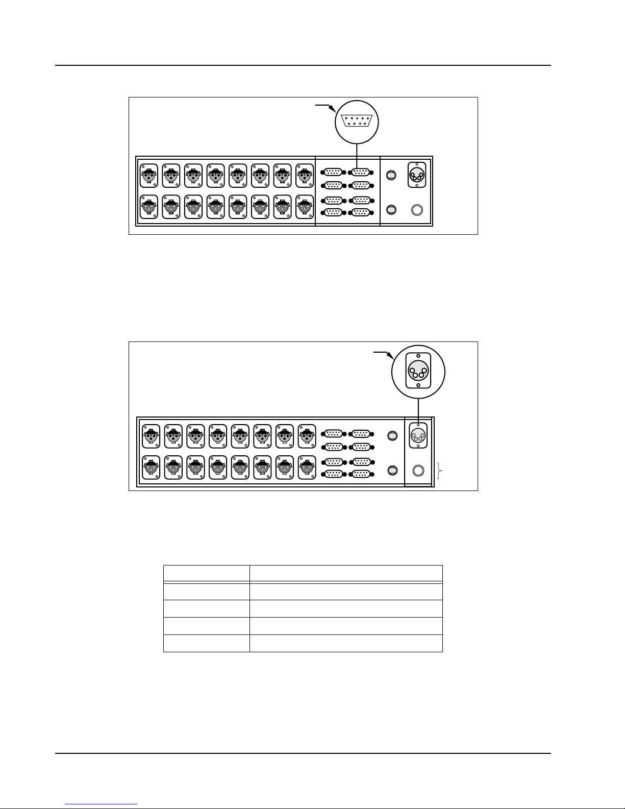
Digital signal connections are made via the 9-pin D connectors described in Table 4 and
illustrated in Figure 9. A 110
needed if cable lengths using 110
W terminating resistor placed across the balanced inputs may be
W twisted pairs are in excess of 6 feet. The serial
communications protocol can be RS-232 at one end and RS-422 at the other, if desired.
Contact closure input is activated by connecting it to ground. Contact closure output is an isolated
dry contact.
If SONY CCU interface operation is selected, RS-422 and RS-232 functions are not available at
that connector.
Table 4. Digital Cable Connections
Pin
Number
Connectors
1, 3, 5, 7 (Left)
1 RS-422 in (-) RS-422 in (-) No connection
2 Contact out No connection
3 Ground Ground Ground
4 RS-232 out RS-232 out No connection
5 RS-422 out (-) RS-422 out (-) Jumper to pin 8
6
RS-422 in (+)
RS-232 in
7 Contact out No connection No connection
8 Contact in No connection Jumper to pin 5
9 RS-422 out (+) RS-422 out (+) No connection
Connectors 2,4,6,8 (Right)
Serial Com. CCU
CCU I/O
Jumper to pin 6
RS-422 in (+)
RS-232 in
CCU I/O
Jumper to pin 2
Installation 7
Page 14
Adder 882
Female 9-Pin D
15
69
AUDIO IN 1
AUDIO OUT 1
AUDIO IN 2
AUDIO OUT 2
AUDIO IN 3
AUDIO OUT 3
AUDIO IN 4
AUDIO OUT 4
AUDIO IN 5
AUDIO OUT 5
AUDIO IN 6
AUDIO OUT 6
AUDIO IN 7
AUDIO OUT 7
AUDIO IN 8
AUDIO OUT 8
1
3
DATA I/O
5
7
2
4
6
8
A (TX)
OPTICAL I/O
B (RX)
DC INPUT
12-24VDC
2AMP, SLO BLO
Figure 9. RS-422 D Connectors on the Rear Panel
The digital I/O connector is AMP 747905-2.
Power Connector
When using the standard Telecast power supply, connect the 4-pin XLR connector to the
Adder 882 and plug the supply into a 120 VAC line. See Figure 10.
Male 4-Pin XLR
1
2
4
3
AUDIO IN 1
AUDIO OUT 1
AUDIO IN 2
AUDIO OUT 2
AUDIO IN 3
AUDIO OUT 3
AUDIO IN 4
AUDIO OUT 4
AUDIO IN 5
AUDIO OUT 5
AUDIO IN 6
AUDIO OUT 6
AUDIO IN 7
AUDIO OUT 7
AUDIO IN 8
AUDIO OUT 8
1
3
DATA I/O
5
7
2
4
6
8
A (Tx)
OPTICAL I/O
B (Rx)
DC INPUT
12-24VDC
2AMP, SLO BLO
Input
Power
Fuse
Figure 10. Power Connector and Fuse Locations
Any power supply used with the Adder 882 must supply 1.5 amperes continuous current. Use the
wiring connections shown in Table 5. The power connector is Switchcraft D4M.
Table 5. Power Connections
Pin Signal
1 Ground
2 Not used
3 Not used
4 +12 to 24 VDC (Abs. Max. 30 VDC)
Input Power Fuse
The 2 ampere time delay power fuse is accessible from the rear panel (see Figure 10). Be sure to
use the same fuse type if replacement is required.
8 1 April 1999
Page 15
Telecast
Operating Details
Battery Charging
Charge the internal UPS batteries at a minimum 13.8 VDC for 16 hours (40 mA trickle charge) by
attaching each unit to its external power supply. This will permit battery operation for up to
20 minutes during line power losses.
Indicators
The three LEDs on the front panel are shown in Figure 11.
EXTERNAL
ON
POWER
POWER
OFF
INTERNAL
RESERVE
LINK STATUS
Figure 11. Front Panel
¥ EXTERNAL POWER . When this green LED is illuminated, an external supply of between 12 and
24 VDC is connected.
INTERNAL RESERVE . This LED is illuminated green when the power is on and the internal
¥
battery is adequately charged. This LED lights after one half hour of charge. There may be a
few minutes of reserve after the indicators extinguish. This LED is illuminated red when the
internal battery is discharging.
LINK STATUS . This red LED is on when the Þber optic link is not properly attached, or the
¥
system units are not communicating properly. This indicator is meaningful only if one of the
other two LEDs is on.
AUDIBLE ALARM . An audible alarm has been incorporated into the Adder 882 in addition to the
¥
LED indicators on the front panel. This alarm alerts the user that the internal batteries are
discharging. A defeat switch for the audible alarm is located inside the unit on the main circuit
board.
ä
ADDER 882
AUDIO/DATA MUX/DEMUX
Telecast
Fiber Systems, Inc.
Powering Up
Note: A locking switch is provided to prevent inadvertent power turn off. Never try to move the
front panel switch without Þrst pulling on the switch lever to disengage its lock.
With power OFF at both units, check all electrical and optical connections as described in
Installation on page 3. Firmly seat and latch all connectors. To operate the power switch:
1. Pull the lever away from the panel.
2. Move it up for power ON, or down for power OFF.
The power switches at both units must be on for the system to achieve normal function.
3. Switch on the power to both Adder 882 units.
Verify that the green
LEDs do not light. If you do not get this result, refer to the Troubleshooting Chart on page 16.
Operating Details 9
EXTERNAL POWER LEDs are illuminated, and that the red LINK STATUS
Page 16
Adder 882
Theory of Operation
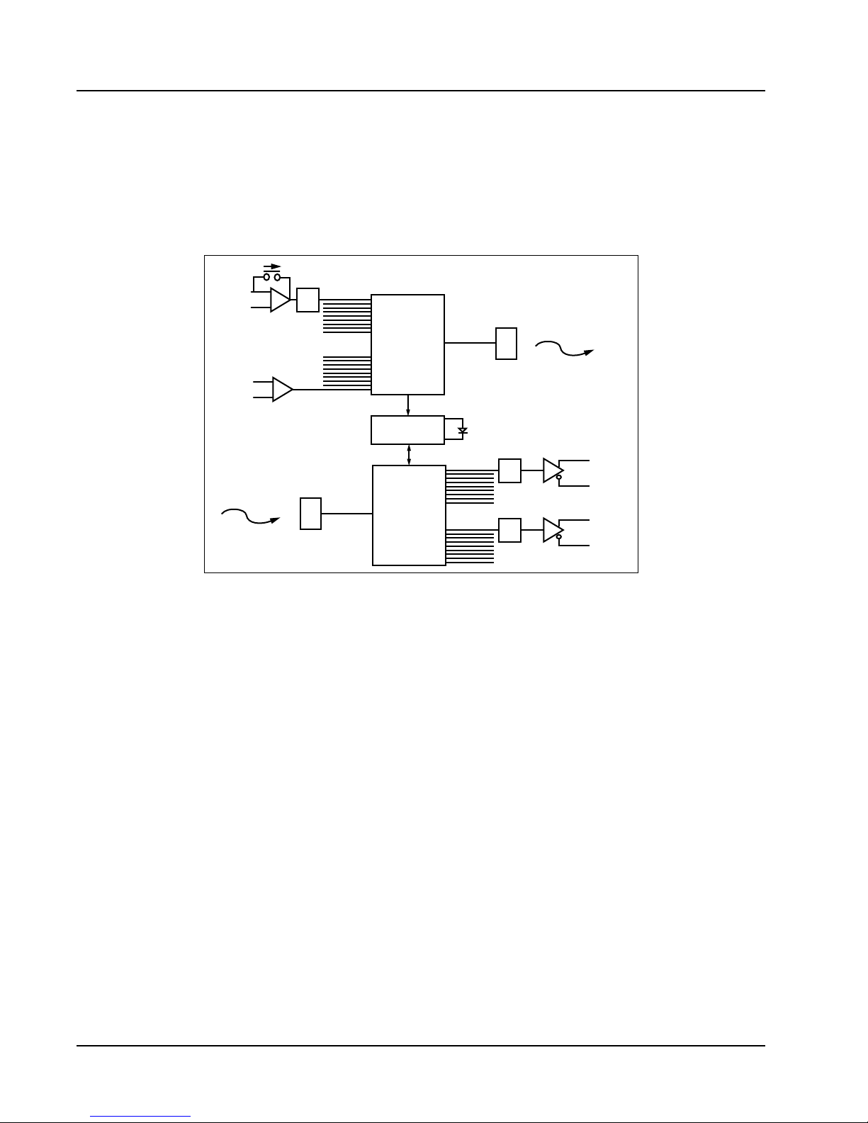
The Adder 882 circuit block diagram is shown in Figure 12. The unit has two basic functions:
multiplexing signals onto an optical Þber, and demultiplexing signals from an optical Þber. The
Adder 882 accepts up to eight audio inputs, eight digital inputs and four remote relay closures and
time division multiplexes them onto a single optical Þber.
GAIN
+
TYP 1 of 8
AUDIO
INPUT/(LINE MIC)
TYP 1 of 8
DIGITAL INPUT/ (RS 422)
A/D
-
FIBER OPTIC CABLE
MULTIPLEXER
+
-
TIMING
TX
LINK STATUS
l
+
TYP 1 of 8
-
AUDIO INPUT
(LINE)
+
TYP 1 of 8
-
DIGITAL INPUT
FIBER OPTIC CABLE
l
D/A
TX
DEMULTIPLEXER
D/A
Figure 12. Electronics Block Diagram
All signals on the optical Þber are digital and, therefore, relatively insensitive to transmission
level variations. As a demultiplexer, the unit separates the multiplexed signals it receives from the
optical Þber and converts the audio information back into analog signals.
There is a one-to-one correspondence between inputs and outputs at opposite ends of the system.
Audio inputs and outputs are on separate sets of eight XLR connectors located on the rear panel.
Refer to Figure 1 on page 1.
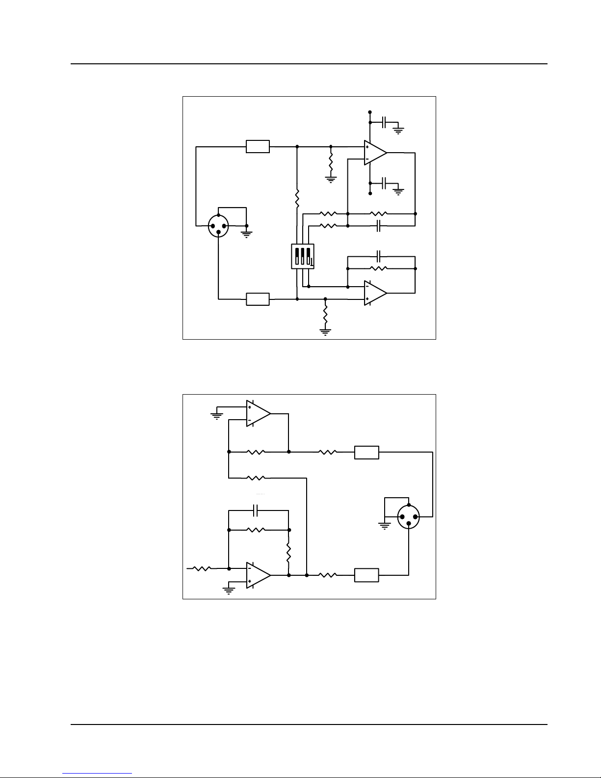
For details on setting up the audio circuits refer to Audio Setup on page 4. Inputs can be set to
have a balanced 600 W or 5 kW buffer circuit that is shown in Figure 13.
The audio input buffer circuit shown in Figure 13 can accept two signal levels:
LINE input, factory default. Set the input buffer to unity gain. The gain of the input can
¥
optionally be set to +10 dB, and the output to -10 dB. This provides a lower noise ßoor, but
decreases the clipping level from +18 dBm to +8 dBm.
MICROPHONE input. Set the input buffer to a gain of 40 dB.
¥
10 1 April 1999
Page 17
1
Ferrite Bead
Telecast
+8
.1
2
2.49k
2
3
8
1
MC33078
4
680
123
4.64k
100
0
2
1
3
Audio In
.1
-8
4.99k
10pF
10pF
Mode
4.99k
7
MC33078
1
Ferrite Bead
654
2
6
5
2.49k
Figure 13. Audio Input Buffer Circuit
The audio output circuit is shown in Figure 14. The output impedance is 30 W, balanced.
10
9
2.0k
2.0k
MC33179
8
15
W
Audio Out
1 2
Ferrite Bead
2.0k
Theory of Operation 11
.015 Film
mF Film
1
4.99k
2.0k
6
5
7
MC33179
15
W
1 2
Ferrite Bead
Figure 14. Audio Output Buffer Circuit
0
2
3
Page 18

Adder 882
Digital I/O
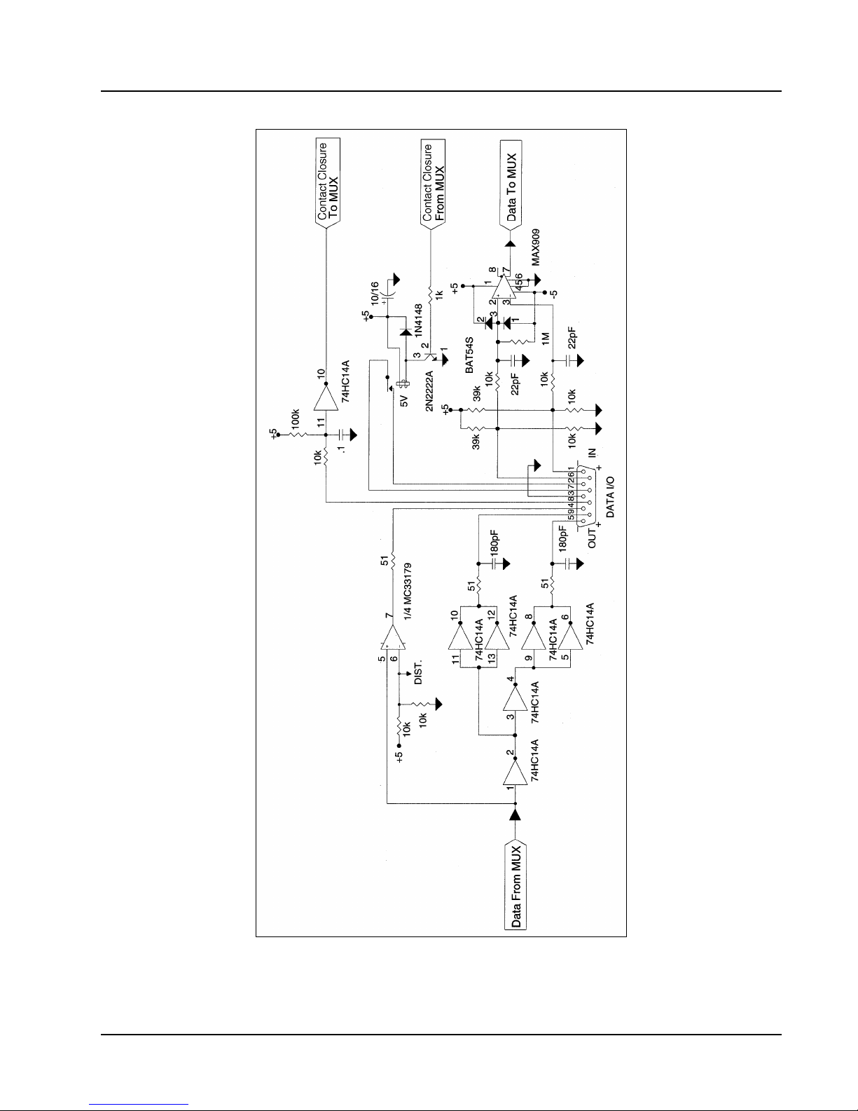
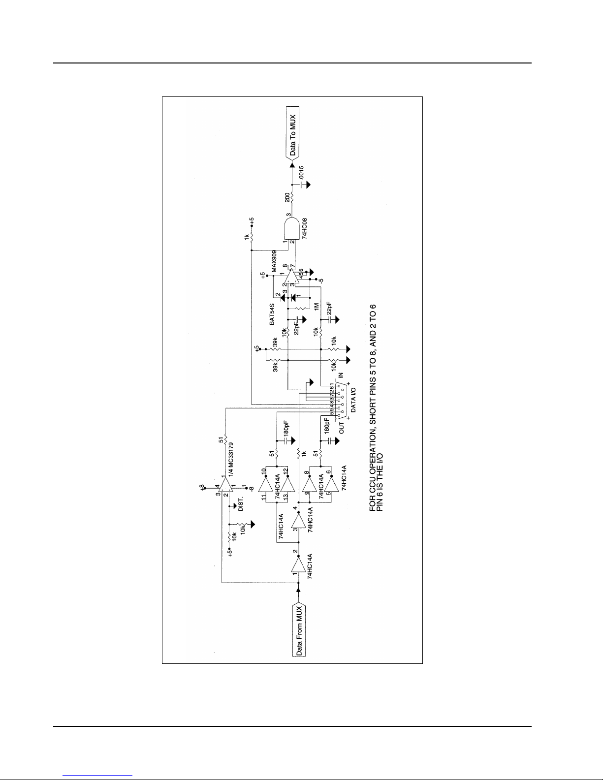
The digital input buffer circuits shown in Figures 15 and 16 accept and drive industry standard
RS-422, RS-423, and RS-232 signal levels. These circuits may be used to convert from one signal
format to another.
The digital output circuit shown in Figure 15 can be conÞgured by the user to provide SONY
CCU compatible I/O; contact closure circuits are not provided on connectors 2, 4, 6, and 8. Refer
to Table 4, ÒDigital Cable Connections,Ó on page 7 for instructions on selecting the CCU
capability. When this option is selected, the RS-422 and RS-232 serial communications for that
connector are not available.
The circuits in Figure 15 also provide contact closure inputs and outputs. The contact closure
inputs are made by connecting pin 8 to ground (pin 3). This may be accomplished with a TTL
output referenced to pin 3 as ground. The output contact closure is an SPST-NO relay and is not
ground referenced.
12 1 April 1999
Page 19
Telecast
Figure 15. Digital I/O Connectors 1, 3, 5 and 7
Theory of Operation 13
Page 20
Adder 882
Figure 16. Digital I/O Connectors 2, 4, 6 and 8
14 1 April 1999
Page 21
Telecast
Optical
The optical output is generated from a high power LED coupled to an optical Þber. User
connections are made at a bulkhead type ST connector at the rear panel. The transmission Þber
must be matched to the Þber pigtail type speciÞed at the time of manufacture. The input uses a pin
diode and ampliÞer to convert the optical signal back into an electrical signal. The optional singleÞber system uses a wavelength division multiplexer to combine and then to separate the two
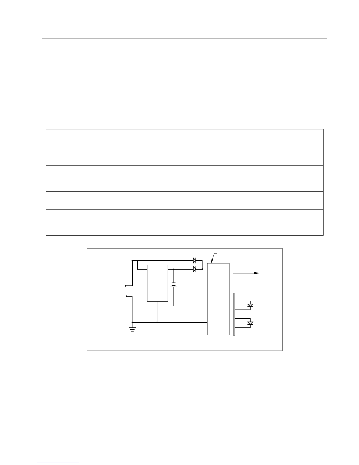
colors used. The main circuits in the Adder 882 are described in Table 6. The basic setup is
illustrated in Figure 2 on page 2.
Table 6. Adder 882 Main Circuits
A/D
Multiplexer
Demultiplexer
D/A
Battery charger
High speed analog to digital converters located in each audio channel.
Sequentially presents eight RS-422 digital inputs and eight digitized audio
signals from the A/D converters to the optical output driver and four to remote
relay closures.
Takes sequential digital signals from the pin diode and separates them into
20 separate lines: eight to the D/A converters, eight to the RS-422 transmitters
and four to remote relay closures.
High speed digital to analog converters located in each audio channel convert
the digitized signal back to analog audio.
The battery charger (Figure 17) is active whenever an Adder 882 unit is
receiving DC power between 13.8 and 24 VDC. Charging current is limited to
a trickle level at any voltage input. Full charge takes 16 hours.
+12 VDC to +24 VDC
4
Rear Panel DC INPUT
1
Charge
Control
Circuit
Internal
Battery
Front Panel
Power Switch
Switch
Mode
Power
Supply
Power to
Electronics
External
Power
LED
Internal
Reserve
LED
Theory of Operation 15
Front
Panel
Figure 17. Battery Charger Block Diagram
Page 22

Adder 882
Preventive Maintenance
Carry out the following procedures every two years:
¥ Replace the internal Ni-Cad battery pack.
¥ Verify the adequacy of optical power at the far end of each optical Þber. Use an optical power
meter such as the one in the Accessory List.
Accessory List
The following accessories are available from Telecast:
¥ Optical power meter kit
¥ Cable repair kit
¥ Loop-back cable to localize signals during installation test
¥ Replacement Ni-Cad battery pack
¥ Quick-crimp kit to attach ST connectors to Þber optic cable
¥ Prefabricated cables built to custom lengths
Troubleshooting
Refer to the troubleshooting chart on the following page. If you are unable to resolve the
problems with your Adder 882 System, call Telecast Fiber Systems, Inc. at 508-754-4858 and ask
for our service department.
To return a unit for repair, obtain a return material authorization (RMA) number from Telecast
service.
16 1 April 1999
Page 23

Table 7. Troubleshooting Chart
Symptoms Possible Cause Corrective Action
Make sure the power switches of both units
No operation, indicators all off No power
are on, and their external supplies are
delivering between 13.8 to 24 VDC.
Telecast
No operation
INTERNAL RESERVE LED off
Normal operation
INTERNAL RESERVE LED red
No operation
LINK STATUS LED on
Very low signal output on one
audio channel
Signal distorted on one channel
Internal reserve battery fails
quickly
System goes dead as soon as
external power is removed
Battery depleted and either
power switch off
Internal battery depleted
Optical communications
failure
Microphone on input with
0 dB selected
Line input with 40 dB
selected
Reserve battery is not
charged
Reserve battery dead or
disconnected
Make sure the power switches of both units
on.
are
Recharge battery.
The light should go back on after 1/2 hour
of use with the AC power adapter. If it does
not go on, replace the battery.
Check for broken or disconnected Þbers or
that the Adder 882 unit at the other end is
not operational. On a one Þber system,
refer to Figure 2 on page 2.
Move internal slide switch to 40 dB
setting.
Move internal slide switch to 0 dB setting.
Connect to power source of 13.8 to 24
VDC for 16 hours.
Check the battery connection.
Replace the battery if necessary.
17
Page 24

Adder 882
SpeciÞcations
Audio Characteristics
Input Signal Levels
600
W balanced (low Zin)
Unity gain +18 dBm peak
+10 dB +8 dBm peak
+40 dB -22 dBm peak
W balanced (high Z
5 k
Unity gain +16 dBV peak
+10 dB +6 dBV peak
+40 dB -24 dBV peak
W, balanced output into 600 Ws
30
Unity gain +18 dBm peak
+10 dB +8 dBm peak
Frequency response @ +8 dBm, from DC to 25 kHz ±
in
)
0.2 dB
Output Signal Level
30
W, balanced output into 600 Ws
Unity gain +18 dBm peak
+10 dB +8 dBm peak
Frequency response @ +8 dBm, from DC to 25 kHz ±
Total Harmonic Distortion
From 20 Hz to 20 kHz (@ +8 dBm) <0.05%
1 kHz (@ +18 dBm) <0.0085%
Intermodulation Distortion (SMPTE Method)
60 Hz + 3 kHz, mixed 4:1 @ +8 dBm <0.04%
Signal to Noise Ratio (unweighted)
20 Hz to 20 kHz, AVG (ref to +18 dBm) >95 dB
0.2 dB
18 1 April 1999
Page 25

Digital Characteristics
Serial Communications
Data Interface Signal Level Data Rate
RS-422 Balanced TTL levels 0-150 kBits/sec*
RS-423 TTL levels 0-150 kBits/sec*
RS-232
Sony CCU** RM-M7, RM-P3 or compatible 0-20 kBits/sec
Jitter 1.12 msecs
*Higher rates possible dependent on user system jitter tolerance.
** Request Telecast Application Note for more information.
Contact Closure
Input TTL Ò1Ó or open circuit Remote contact open
Output (Form 1A SPST-NO isolated contacts)
Telecast
± 8 V
p-p
0-38.4 kBits/sec
TTL Ò0Ó or shorted to circuit ground Remote contact closed
Voltage 200 VDC
Switched current 500 mA
Carry current 1.2 A
Contact resistance 200 mW
Optical Characteristics
System Margin Data (1-Þber/2-Þber)
Operating Wavelength 850 nm 1300 nm 1550 nm
TX Output into cable -16*/-18 dBm -15/-13 dBm -15/-13 dBm
RX Sensitivity -24*/-26 dBm -28/-30 dBm -28/-30 dBm
*62.5 mm Þber only.
Power Requirements
Voltage 12 to 24 VDC
Current 1.5 amperes, maximum @ 13.8 VDC
Note: Although the units will operate at 12 VDC, 13.8 VDC is required to charge the internal
reserve battery.
Caution: Absolute maximum voltage is 30 VDC. Equipment damage may occur at higher
voltages.
19
Page 26

Adder 882
Warranty
LIMITED WARRANTY STATEMENT
Telecast Fiber Systems, Inc. (ÒTelecastÓ) expressly warrants to Buyer that the Products supplied shall be free from defects in materials and workmanship
for a period of 12 months following the date the Products are delivered to Buyer (the ÒWarranty PeriodÓ). Telecast's liability under this limited warranty
shall be limited, at its option, to providing refund of purchase price for Products, or replacing or repairing Products shown to be defective either in
materials or workmanship. Buyer's sole and exclusive remedy for breach of warranty shall be such refund, replacement or repair.
A claim of defect in materials or workmanship in any Product shall be allowed only when it is submitted in writing to Telecast Fiber Systems, Inc. within
seven days after discovery of the defect, and in any event within the Warranty Period. No claim shall be allowed in respect of any Product which has
been altered, neglected, damaged or stored in any manner which adversely affects it. In order to obtain service under the terms of this warranty,
DistributorÕs customer or Distributor must notify Telecast of the defect prior to the expiration of the applicable warranty period and obtain a Return
Authorization Number from Telecast. In no event may products be returned to Telecast or to Distributor for warranty service without having obtained
from Telecast a Return Authorization Number.
This limited warranty applies only to new and unused Products delivered to Buyers located within the United States of America, or to international
Buyers if sold through an authorized Distributor organization, and shall not extend to any equipment not manufactured by Telecast Fiber Systems, Inc.,
even though such equipment may be sold or operated with the Products. In addition, this limited warranty shall be void and of no further force or effect
whatsoever if the Product is repaired or modiÞed by any person other than an authorized representative of Telecast Fiber Systems, Inc. without the
consent of Telecast Fiber Systems, Inc. This warranty shall not apply to any defect, failure or damage caused by improper use or inadequate maintenance
and care. Nor shall this warranty apply to any damage caused in whole or in part by attempts by personnel other than TelecastÕs personnel, as approved
in advance in accordance with the foregoing provisions, to open, install, repair, or service the Product; nor to damage resulting from improper
connection with incompatible equipment; nor to damage to a unit which has been modiÞed by personnel other than Telecast personnel.
Products returned to Telecast for warranty service shall be shipped, freight prepaid to Telecast. Telecast will return the repaired product or ship a
replacement, freight prepaid, to either Distributor or DistributorÕs customer, as requested by DistributorÕs customer, at a location within the United States
or, at TelecastÕs option, to DistributorÕs location in the case of international sales.
This limited warranty shall also apply to Products that replace defective Products and Products that have been repaired by authorized representatives of
Telecast Fiber Systems, Inc., but only for the original Warranty Period. The Warranty Period shall not be extended by reason of defect, or any period of
time during which the Product is not available to Buyer because of defects or repairs, without the express written consent of Telecast Fiber Systems, Inc.
EXCEPT FOR THE EXPRESS LIMITED WARRANTY AGAINST DEFECTS IN MATERIALS AND WORKMANSHIP CONTAINED HEREIN,
TELECAST FIBER SYSTEMS, INC. MAKES NO WARRANTY OF ANY KIND WHATSOEVER, EXPRESS OR IMPLIED, AND ALL
WARRANTIES OF MERCHANTABILITY, FITNESS FOR A PARTICULAR PURPOSE, AND OTHER WARRANTIES OF WHATEVER KIND
ARE HEREBY DISCLAIMED BY TELECAST FIBER SYSTEMS, INC. THIS LIMITED WARRANTY SETS FORTH EXCLUSIVELY ALL OF
TELECAST FIBER SYSTEMS, INC.'S LIABILITY IN CONTRACT OR OTHERWISE IN THE EVENT OF A DEFECTIVE PRODUCT.
WITHOUT LIMITATION ON THE FOREGOING, TELECAST FIBER SYSTEMS, INC. EXPRESSLY DISCLAIMS ANY LIABILITY
WHATSOEVER FOR ANY DAMAGES INCURRED DIRECTLY OR INDIRECTLY IN CONNECTION WITH THE SALE OR USE OF, OR
OTHERWISE IN CONNECTION WITH, THE PRODUCT, INCLUDING WITHOUT LIMITATION, LOSS OF PROFITS AND SPECIAL,
INCIDENTAL OR CONSEQUENTIAL DAMAGES, WHETHER CAUSED BY NEGLIGENCE OR OTHERWISE, REGARDLESS WHETHER
TELECAST HAS BEEN GIVEN ADVANCE NOTICE OF THE POSSIBILITY THEREOF.
THIS WARRANTY IS GIVEN BY TELECAST IN LIEU OF ANY OTHER WARRANTY EXPRESSED OR IMPLIED.
20 1 April 1999
 Loading...