

Page 1

Adder™ 162/322
Audio/Intercom/Data Multiplexer
User Manual
Telecast Fiber Systems, Inc.
102 Grove Street
Worcester, MA 01605
Tel: 508-754-4858
Fax: 508-752-1520
www.telecast-fiber.com
Page 2

Page 3

Table of Contents
Introduction 5
Overview 5
Coaxial Cable Input and Output 5
Status Indicators 5
Battery Backup 5
Audio Input and Output 5
Data Input and Output 5
Representative System 6
Options 6
Unpacking 6
Optical Fiber 7
Installation of the Assembly 7
Line Power 7
Line Power Connection 7
Input Power Fuse 7
DC Current Requirements 9
Battery Charging 9
Electrical Hookups 9
Audio Connections 9
Digital Connections 10
Optical Connections 11
Optical Fiber Signals 11
Cable Fabrication 11
Fiber Ports 11
Multiple Fiber Versions 12
WDM Single Fiber Versions 12
Coaxial Cable Ports 12
Cable Runs 12
Fiber 13
Input and Output Module Connections 13
Removing and Replacing Modules 15
Optical Fiber or Coax Communication Selection 16
Switch Settings (older rev only) 16
Coax Length (older rev only) 16
Audible Alarm Settings 17
Local Power Alarm 17
Remote Power Alarm 17
Page 4

Audio Signal Setup 18
Input Module Setup 19
Gain 19
Impedance 19
Grounding 19
Auxiliary Items 21
Signal Generator/Monitor 21
Status Indicators 22
Power Supply 22
Status 22
Received Signal Level 23
System Interconnections 24
Powering Up 25
Intercom Modules 25
Intercom Connections 27
4-wire Auxiliary (balanced) 27
Clear-Com 28
RTS Telex 29
Intercom Module Replacement 30
Cable Harness 30
Intercom Setup Switches 30
Theory of Operation 32
Data Connectors 32
Audio Circuits 34
Preventive Maintenance 36
Accessory List 36
Troubleshooting 37
Measuring Optical Power 37
Specifications 38
Repair 40
Warranty 41
Page 5

Introduction
Overview
The Telecast AdderTM 162 (32 channels) and Adder 322 (64 channels) are modular, multichannel communications systems designed for the transmission of high-quality audio, data and
intercom functions. The units pre-amplify, digitize, multiplex, transmit and receive up to 64
channels of audio information, four data channels and three dual-channel intercoms over one or
two optical fibers or 2 coaxial cables. Audio path evaluation is achieved using a built-in audio
signal (tone) generator and level meter/monitor.
Modules contain eight connectors for mic (high or low impedance) or line level inputs, or eight
output connectors for signals de-multiplexed from the send/receive fiber.
The Adder 162 accepts up to four modules in any combination for a total of 32 channels in a
6RU, 10 inch high x 19 inch wide electronic equipment rack. The Adder 322 accepts up to eight
modules for a total of 64 channels in a 10RU, 17.5 inch high x 19 inch wide electronic
equipment rack.
Coaxial Cable Input and Output
Each assembly has a coaxial input and output on which all signals are multiplexed. There is no
redundancy in the coaxial system. On older versions, the coaxial input is activated by internal
DIP switches on the Main PC Board. The coaxial output is always active. On newer models, the
dip switches are gone and the units work on coax priority. That is to say that the system looks
for the coax link first and then, if it does not see one, switches to optical.
Status Indicators
The front panel of the Adder 162/322 contains LED status indicators that monitor audio signals,
the DC power source, and the communication link status.
Battery Backup
A Ni-Cad emergency battery backup is built into the assembly. Battery backup is limited to
approximately 20 minutes and should be considered short-term power loss protection. The
available Telecast power module (ADAP-AC-03 or Eel) provides continuous battery charging
during line power operation.
Audio Input and Output
Audio input levels are set up for each channel by switches on the front of each input module.
These switches set input gain from 0 to 40 dB, input resistance to 600 Ohm or 10 kOhm and a
+48 VDC bias voltage to power microphones either ON or OFF. A ground lift switch is also on
the front panel for use with each channel.
Audio outputs are at line level. There are no operator controls on the output modules.
Data Input and Output
The Model 162/322 assembly accepts and multiplexes four digital data signals and two remote
relay closures onto the output fiber. The receiving assembly accepts the transmission, restores
Page 6
the digital signals and provides the switch closures. The number of data channels is fixed and
independent of the number of audio channels in the assembly.
Representative System
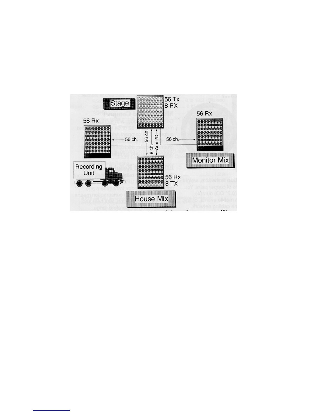
The flexibility offered by 64 channels of audio and the capability of having both input and output
modules in a single assembly can lead to many efficient and innovative hookups. A
representative system using the Telecast 322 in a 3-way split is shown in Figure 1.
Figure 1: Adder 322 with a 3-way Split
Options
Configure the 162/322 system by selecting the following options. Contact Telecast for details.
AI820 8-channel Input Module
AO820 8-channel Output Module
4-wire Intercom
Clear-Com 2-wire Intercom
RTS/Telex dual-channel Intercom
Multi-mode WDM (Wavelength Division Multiplexer)
Single-mode WDM
Unpacking
The Adder 162/322 minimum configuration consists of one input and one or more output
modules. Input (Model AI820) and output (Model AO820) modules are installed and tested by
Telecast prior to shipment, in accordance with customer specifications. In addition, microphone
impedance and bias is preset per customer order, as is preamplifier gain for each channel. In
addition to the Model 162/322 assembly with its Input and Output Modules, a system also
includes:
External power supplies (AC/DC adapters)
Protective covers for optical connectors
Hardware kits for rack mounting the units
Page 7
Optical fiber
After unpacking, inspect the units for mechanical damage, and electrical connectors for bent or
damaged pins. Report any damage to the carrier and to Telecast Fiber Systems, Inc.
Leave the protective caps on the optical connectors until it is time to attach the fiber to the units.
Replace the caps onto the connectors whenever the fiber is disconnected.
Installation of the Assembly
Units are shipped ready for rack use. Some Adder 162/322 connections can be made at the
front or rear panel, which would have been determined when the order was placed. For bench
use, remove the rack mounting flanges by unscrewing them at three places along each flange.
Line Power
The external power supplies provided with each assembly require 120 VAC. Be sure that AC
outlets are within reach of their 6-foot power cords. If your Adder is equipped with intercoms that
require power (RTS or Clear-Com), you will need two such power supplies per frame.
Line Power Connection
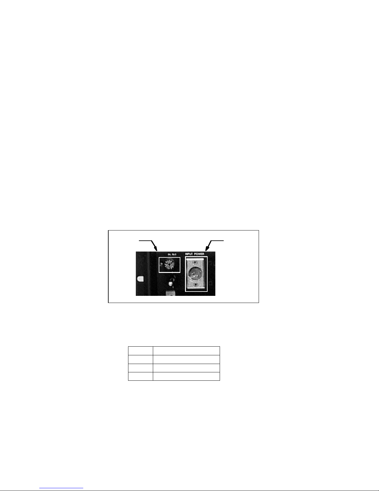
Insert the 4-pin XLR connector from the Telecast power supply into the INPUT POWER
Switchcraft D4M receptacle located at the upper left corner or rear of the 162, and located at the
lower right corner or rear of the 322. Plug the supply into a 120 VAC line. See Figure 2 and
Figure 3 for the power connector locations and Table 1 for electrical connections.
Fuse
XLR
Power
Figure 2: Input DC XLR Power Connector and Fuse
Table 1: XLR Power Connections
PIN SIGNAL
1 Ground
2 & 3 Unused
4 + Input VDC
Input Power Fuse
The SLO BLO power fuse in Figure 2 and Figure 3 is located next to the INPUT POWER
connector. Use a 6.25 Amp 5 x 20 mm approved fuse type for both Model 162 and Model 322.
Be sure to use the same fuse type if replacement is required.
Page 8
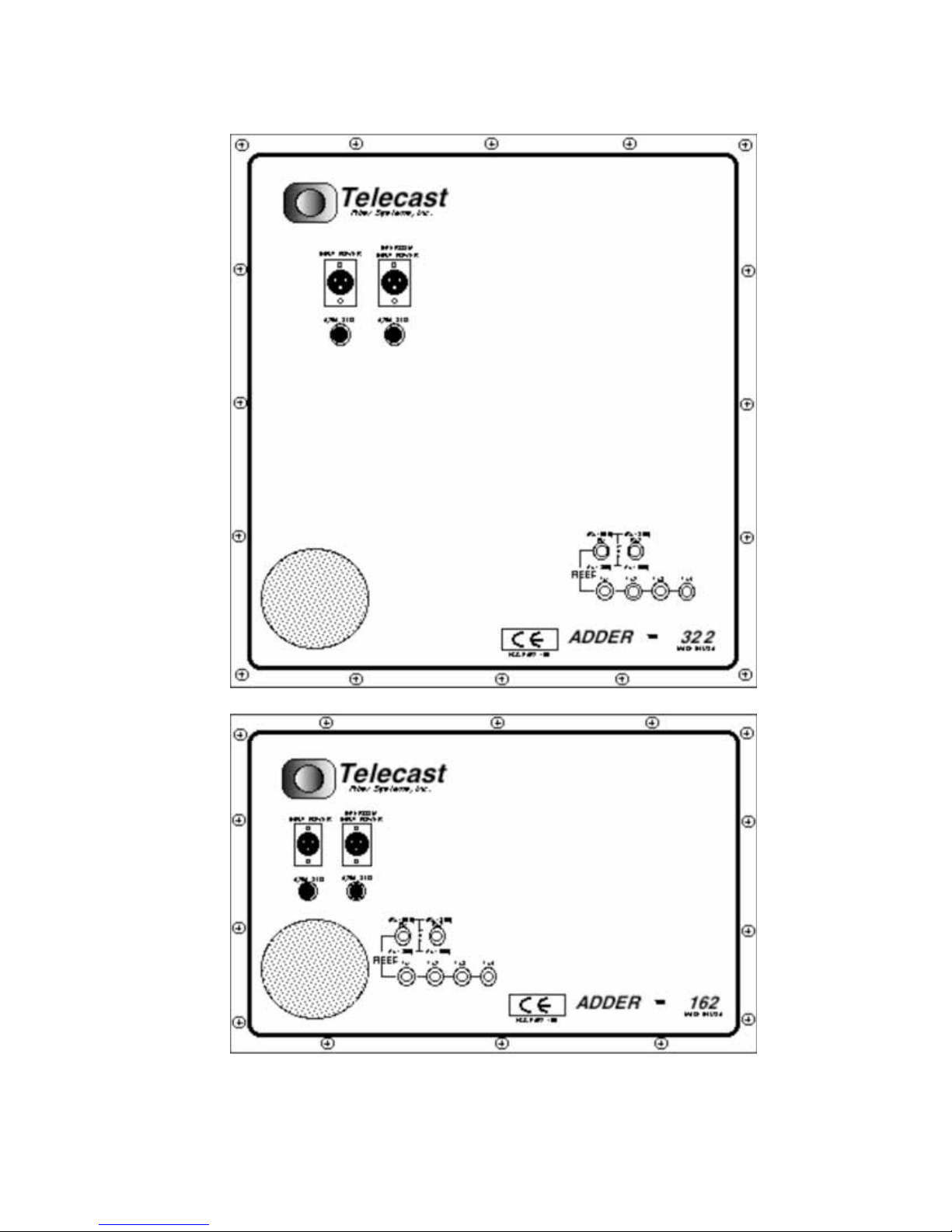
Figure 3: Adder 322 and 162 rear panels
Page 9
DC Current Requirements
3
Any 15 VDC external power supply used with the Adder 162 must provide 2.5 amperes
continuous current.
Any 15 VDC external power supply used with the Adder 322 must provide 3.5 amperes
continuous current.
Although the Adder 162/322 assembly will operate at 10 VDC, ≥13.8 VDC is required to charge
the internal backup battery. System operation below 15 VDC can cause battery charge
depletion.
Battery Charging
The internal battery is automatically charged whenever 13.8 VDC is provided at the INPUT
POWER connector shown in Figure 2 on page 3. Full charge takes 16 hours, and will power
Model 162 for 30 minutes and Model 322 for 15 minutes.
Electrical Hookups
Audio Connections
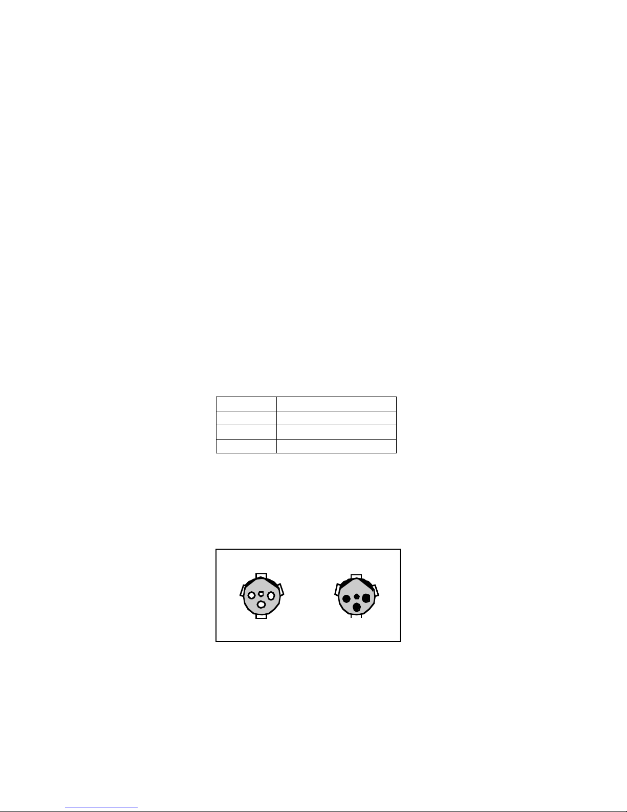
Audio I/O is via 3-pin XLR connectors with industry standard wire locations. See Table 2 and
Figure 4.
Table 2: XLR Audio I/O Cable Connections
PIN SIGNAL
1 Ground
2 Balanced I/O (-)
3 Balanced I/O (+)
The XLR connectors are located on the front panel of each module. On the input modules, XLR
connectors are female Neutrik type NC3FPR-H. On the output modules, XLR connectors are
male Neutrik type NC3MG-H. Refer to Figure 4.
INPUT (Female) OUTPUT (Male)
1221
Figure 4: XLR Connectors on Input and Output Modules
3
Page 10
Digital Connections
The Model 162/322 assembly accepts and multiplexes four RS-232C or RS-422 digital data
signals and two remote relay closures. The 162/322 is also used to receive a transmission,
restore the digital signals and provide switch closures. The number of data channels is fixed and
independent of the number of audio channels in the assembly. Both data input and output are
accomplished on the same connector.
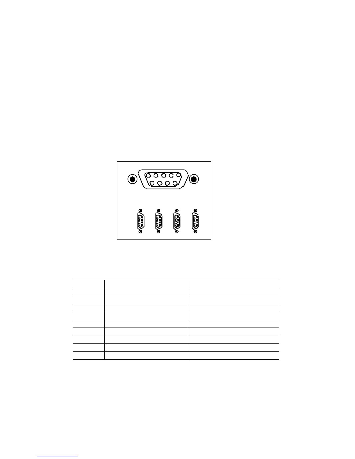
Digital signal connections are made via 9-pin D connectors; see Figure 5. The connection
specifications are listed in Table 3. A 110 Ohm terminating resistor placed across the balanced
inputs may be needed if input cable lengths are in excess of 6 feet. Serial communications can
be RS-232 at one end and RS-422 at the other, if desired.
Contact closure input is activated by pin 8 on contact to ground or to a TTL logic 0 signal level.
Contact closure output is established by an isolated, normally open, dry contact built onto the
Main PC Board.
51
DATA I/O
12 34
69
Figure 5: 9-pin D-connectors
Table 3: Digital Cable Connections
PIN Connectors 1 & 2 Connectors 3 & 4
1 RS-422 in (-) RS-422 in (-)
2 Contact out No Connection
3 Ground Ground
4 RS-232 out RS-232 out
5 RS-422 out (-) RS-422 out (-)
6 RS232/422 in (+) RS232/422 in (+)
7 Contact out No Connection
8 Contact in No Connection
9 RS-422 out (+) RS-422 out (+)
The four digital I/O connectors are AMP 747905-2, D subminiature female or equivalent.
Page 11
Optical Connections
WARNING: Never look directly into the end of the optical fiber until it has been positively
determined to be safe. Eye damage could result.
Optical Fiber Signals
Each 162/322 system has multiple optical connections. As a minimum, a transmit output must
be connected via a suitable fiber to a receive input.
Fiber transmissions can be 100% redundant. A secondary fiber output operates with
independent drivers and is always active. If the active fiber link fails, an alarm is sounded and
the secondary link takes over.
Two additional, fiber outputs are available for local splits. This is useful when the same outputs
are received at multiple locations.
The Adder 162/322 is compatible with industry standard ST type connectors. It may be used
with installed backbone cables or with dedicated cables. Consult Telecast for information
regarding compatible fiber types.
Cable Fabrication
Assembled cables and connectors are available from Telecast Fiber Systems, Inc. For custom
cable fabrication, use type ST connectors such as Telecast part number CONN-ST-M.
Always follow the connector manufacturer’s directions when fastening a connector to the cable.
A Quick-crimp kit, part number CKIT-3M, is available from Telecast.
Always cover all unused fiber connectors.
Transmission Fiber Ports - Multiple Fiber Versions
TX1, TX2, TX3 and TX4
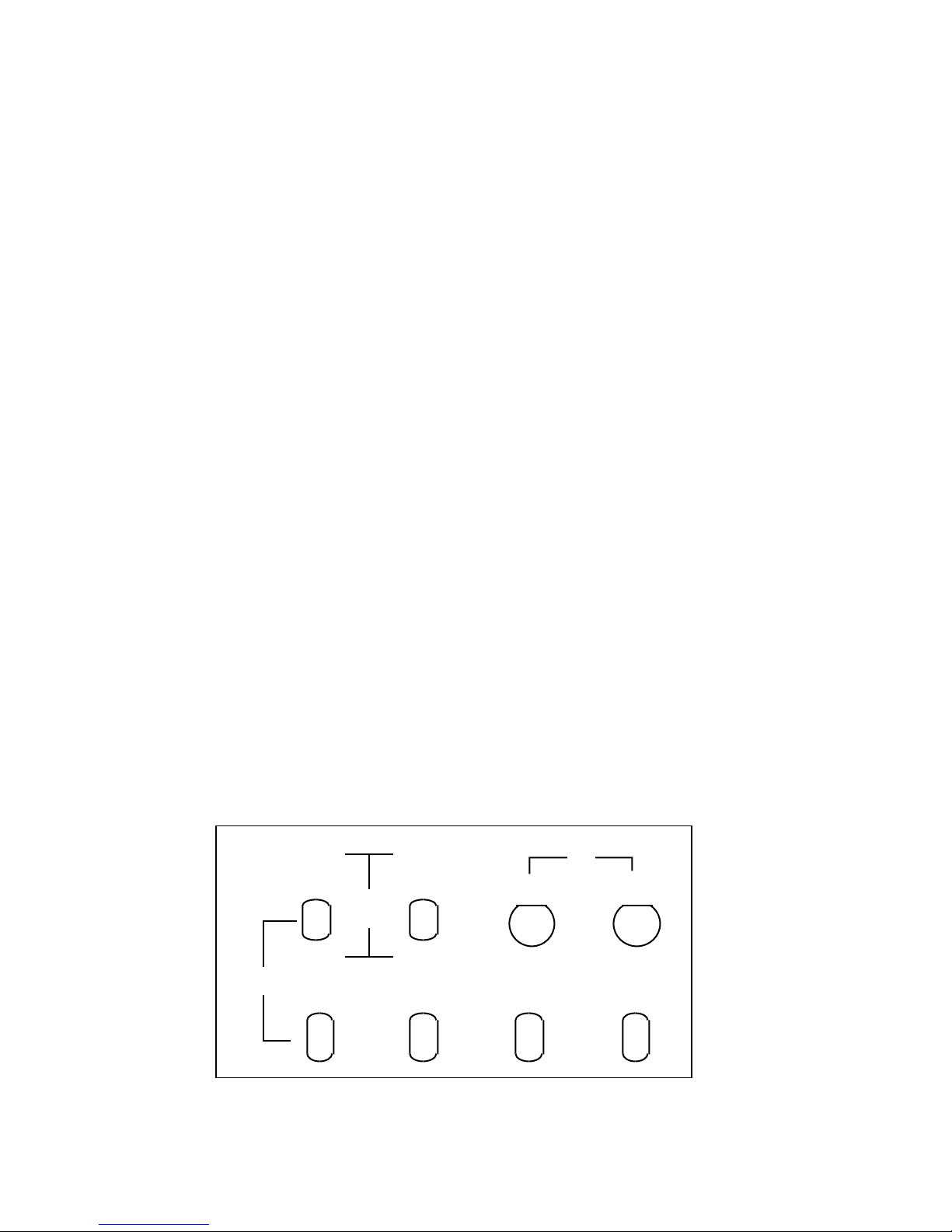
Fiber ports Tx1, Tx2, Tx3 and Tx4 shown in Figure 6 are fully redundant. All transmit ports are
always active and have independent output circuits.
FIBER
(Rx 1550) (Rx 1300)
Rx1 Rx2
W
D
M
(Tx 1300) (Tx 1550)
Tx1 Tx2
Rx Tx
Coax
Tx4Tx3
Figure 6: Fiber and Cable Ports
Page 12

All ports carry digitized, multiplexed audio as well as digital and contact data. Each output has
the same capacity with distance capabilities as shown in Table 4. Unless otherwise specified, all
transmitters operate at 1300 nm except Tx2 which operates at 1550 nm.
Rx1 and Rx2
Fiber ports Rx1 and Rx2 accept the multiplexed optical signals from the output of another Model
162/322. The received signal is demuxed and sent to the output corresponding to the original
input on the transmitting assembly. These fiber input ports are internally switched with
preference to Rx1. If the active port fails to recognize a signal, the assembly switches to the
alternate port and an alarm sounds. An alarm also sounds if neither port has a signal present.
WDM Single Fiber Versions
The Rx ports in Figure 6 on page 7 are used to send and receive optical signals over a single
fiber on assemblies with Telecast’s Wavelength Division Multiplexer option (WDM). This is
accomplished by transmitting on one wavelength and receiving from the same fiber on an
alternate wavelength.
Since each unit is identical, Rx1 must be connected to Rx2 on the second unit to complete the
optical circuit. A redundant circuit from Rx2 on the first unit and Rx1 on the second unit can be
added using a second fiber.
The Tx1 and Tx2 ports are combined with the Rx1 and Rx2 ports by the WDM. Tx3 and Tx4
remain active and are still available for local splits.
Coaxial Cable Ports
Coaxial ports Rx and Tx carry the same data as the optical ports. The coax output is always
active. On older Adders, the coax input is active only when the optical receive inputs have been
disabled via SW1. Coax operation cannot be used as redundancy for the optical circuit.
Fiber Cable Runs
The installer is responsible for providing the fiber optic cable runs, available from Telecast Fiber
Systems, Inc. The Accessory List on page 31 shows cable and other items required for the
system. Be sure that the fiber types are compatible with the intended installation distances, as
shown in Table 4.
Table 4: Distance Limits by Fiber Type
Fiber Type Distance Limit
50/62.5/125 multimode 10 km
8/125 singlemode 20 km
All outputs and inputs of the standard unit are multimode (mm) and single mode (sm)
compatible. Tx2 is 1550 nm and all other transmissions are 1300 nm. When the WDM option is
ordered, the use of sm or mm must be specified.
If the WDM is installed, the fiber used must match that of the WDM to assure functionality.
Page 13
Inspect and clean the fiber ends with clean, dry compressed air or with Kim-Wipes and isopropyl
alcohol. Fingerprints, or other dirt on the optical connector end surfaces, will reduce the
received optical signal level.
Coax
To use the system with coax instead of optical fiber, use Belden 8281, 75 Ohm or equivalent.
Refer to Optical Fiber or Coax Communication Selection on page 16 for the switch settings on
the Main PC Board which govern coaxial use with older Adder 162/322.
Input and Output Module Connections
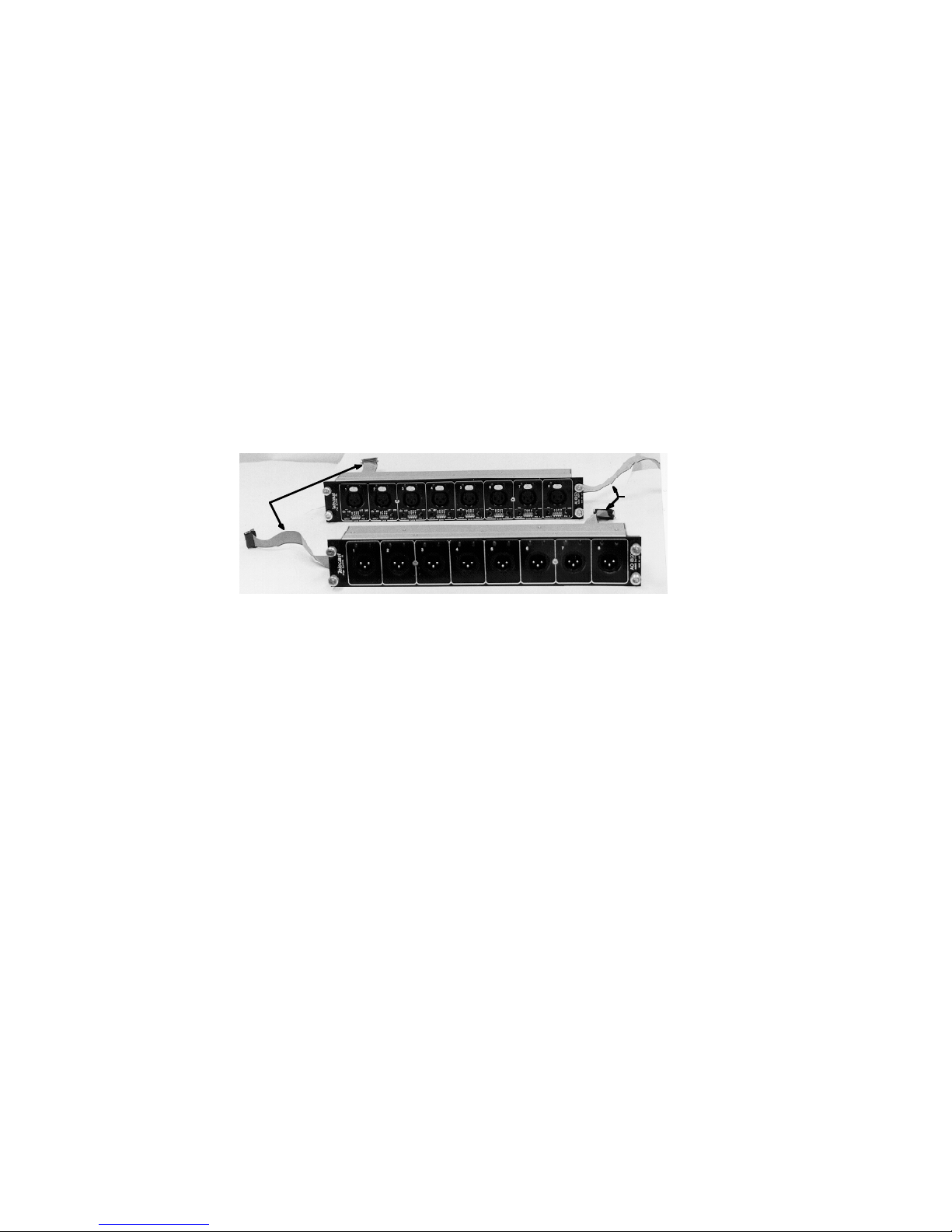
Figure 7 shows an Input Module and an Output Module. The left ribbon on each module is the
signal conductor; the right ribbon provides power. Each ribbon plugs into a specific spot on the
Main PC Board; refer to Figure 8a on page 10.
Signal
Power
Figure 7: Input (upper) and Output (lower) Modules for Adder Model 162/322
Module mounting slots are numbered from the upper part of the chassis to the lower part: A to D
on Model 162, and A to H on Model 322. The Model 162/322 Main PC Board has two sets of
signal and power ribbon connector terminations. See Figure 8.
Signal Ribbons (left side of main board) J11 to J8 are for signal ribbons A to D on Model
162/322. J7 to J4 are for signal ribbons E to H on Model 322.
Power Ribbons (right side of main board and auxiliary board) J24 to J21 are for power ribbons
A to D on Model 162/322. Power for modules E to H on Model 322 is supplied from an
additional power supply board located below the Main PC Board. See Figure 9 on page 14.
Other than module count, number of multiplexed signals, and size, the Models 162 and 322 are
identical in all respects.
Page 14
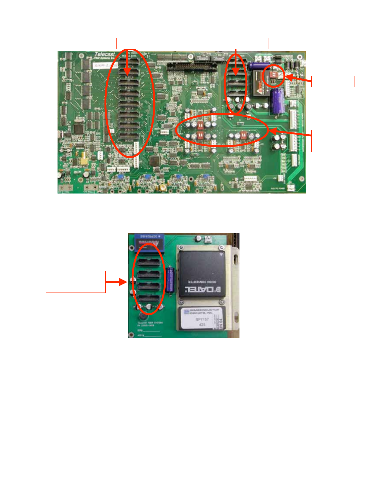
More Module
Power on 322’s
ICOM
GAINS
Figure 8: Model 162 Main PC Board
Figure 9: Model 322 Auxiliary Power PC Board
Page 15
Removing and Replacing Modules
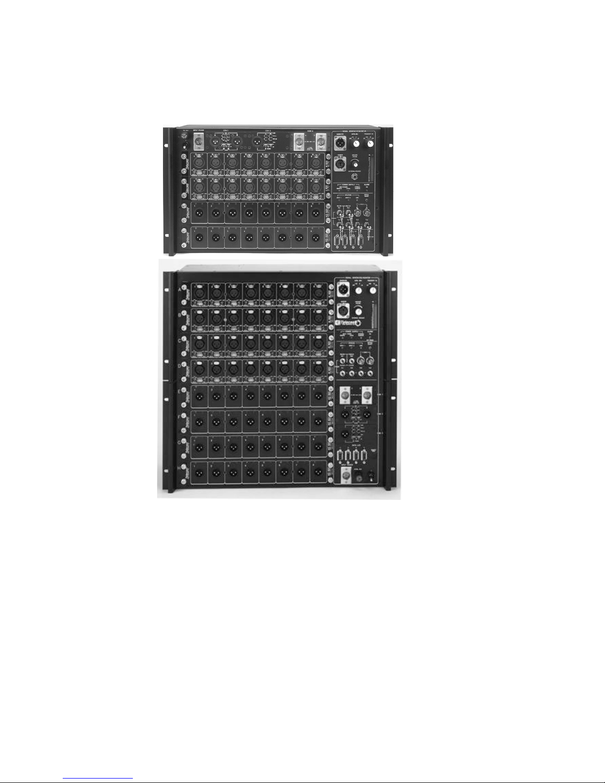
Figure 10 shows a Model 162 assembly and Figure 10 shows a Model 322 assembly.
Figure 10: Adder 162 and 322 - Modules
To change the configuration of your Adder 162/322 assembly:
1. Switch the power to the assembly OFF.
2. Loosen the two mounting screws at the left and right of the module.
3. Unplug the ribbon connectors at either end of the modules. Note that the connections
have spring locks that must be squeezed to be removed.
4. Change the module, and plug the respective signal and power connectors back into
their ports on the module. Tighten the mounting screws.
WARNING: Be sure to maintain the module location number from top to bottom in terms of
module location and connector position on the Main PC Board. An output module at
a given position must correspond to an input module at the same position at the
other end.
Pins on the ribbon connectors are very small in order to best use the very limited amount of
space in the Adder. Be careful not to bend pins when mating ribbon cables to their connectors.
Page 16
Optical Fiber or Coax Communication Selection
Switch Settings
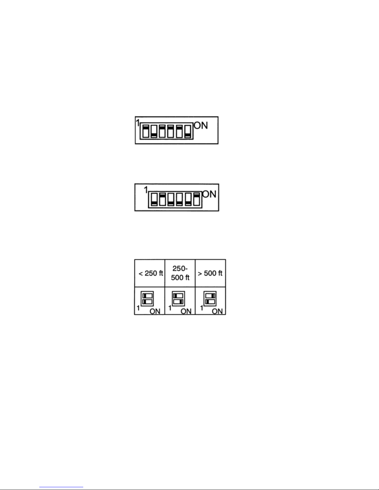
Switches on the Main PC Board control connectors between Adders over either fiber or coax.
Locate SW1 in the lower left corner of the Main PC Board (Figure 8a on page 10).
To receive from optical fiber, configure SW1 according to Figure 11.
Figure 11: Optical Fiber Receive Switch Setting
To receive from coax, configure SW1 according to Figure 12.
Figure 12: Coax Receive Switch Setting
Coax Length
Configure SW2 according to the length of coaxial cable being used. Refer to Figure 13.
Figure 13: Coax distance Settings
The maximum length of coaxial cable that can be used on any single run between assemblies is
1000 feet.
On newer versions, these switches do not exist and the units function in “Coax priority”. This
means that the systems first looks for a coaxial link. If one is not found, the system automatically
begins looking for an optical link. In addition, SW2 is also gone and coax lengths are handled by
an automatic coaxial length equalization circuit.
Page 17
Audible Alarm Settings
An audible alarm is provided to indicate error conditions. This alarm can be deactivated by the
front panel ALARM ON/OFF-RESET switch. Refer to Figure 19 on page 22. In addition, the
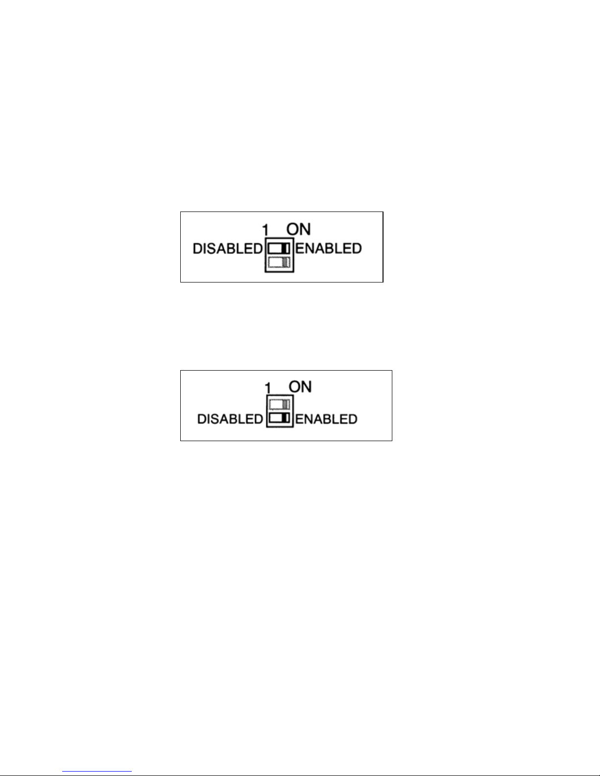
REMOTE POWER and LOCAL POWER alarms can be disabled internally by SW6. Locate
SW6 in the upper right corner of the Main PC Board (Figure 8a on page 14).
Local Power Alarm
The LOCAL POWER ALARM indicates a failure in the external power input at this unit. To
configure the alarm for local power, configure SW6 according to Figure 14.
Figure 14: Alarm Switch — Local
Remote Power Alarm
The REMOTE POWER ALARM indicates a failure in the external power input at the remote unit
(i.e., the unit transmitting to this unit). To configure the alarm for remote power, configure SW6
according to Figure 15.
Figure 15: Alarm Switch — Remote
Alarms are latching. If an alarm occurs, the Audible alarm will sound until the front panel alarm
switch is set momentarily to OFF.
Page 18
Audio Signal Setup
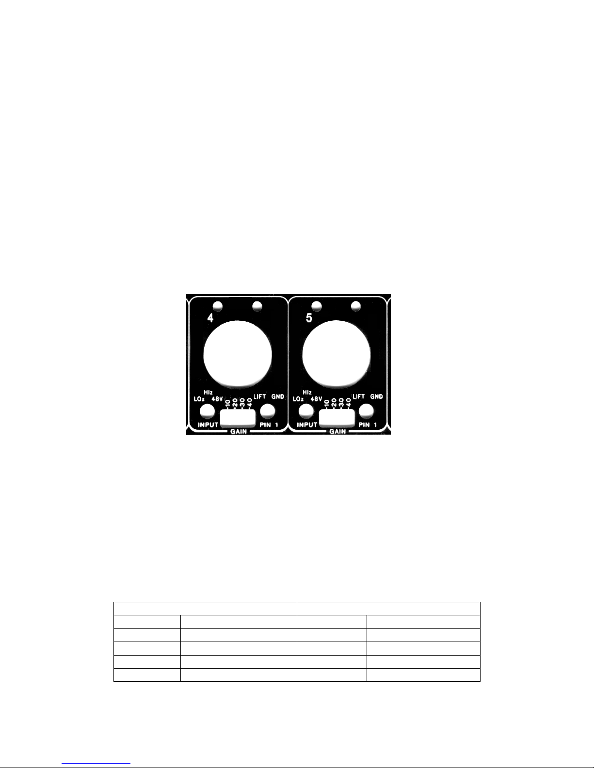
The switches for line or mic input levels, gain, and ground are positioned below the audio
connectors on the front panel of each input module. There are eight sets of switches, one set for
each channel. Channels are numbered left to right from 1 to 8. The panel switch markings for
channels 4 and 5 are shown in Figure 16.
The Model 162/322 system uses high frequency pre-emphasis on all audio channels. Maximum
level at 1 kHz with all gain switches off (unity gain) is +18 dBm. Maximum level at 20 kHz is
10dB lower, or +8 dBm.
The green LED indicates that a signal 30 dB below maximum, or -12 dBm or greater is present
at the channel input. The red LED indicates clipping, indicating that the A/D converter for the
channel is at or near overload and input gain or level must be reduced.
Figure 16: Input Audio Channel Switch Markings
Each channel setting should be carefully checked.
Output module gain is fixed. Maximum module output is +18 dBm, at 1 kHz, corresponding to
A/D clipping.
The LOz /HIz /48V INPUT switch (Figure 16) coupled with the input gain switches result in the
input signal levels shown in Table 5.
Table 5: Input signal levels
LOz, 600 Ohm balanced HIz, 10 kOhm balanced
Unity gain +18 dBm peak Unity gain +18 dBm peak
+10 dB +8 dBm peak +10 dB +6 dBV peak
+20 dB -2 dBm peak +20 dB -4 dBV peak
+30 dB -12 dBm peak +30 dB -14 dBV peak
+40 dB -22 dBm peak +40 dB -24 dBV peak
Page 19
Input Module Setup
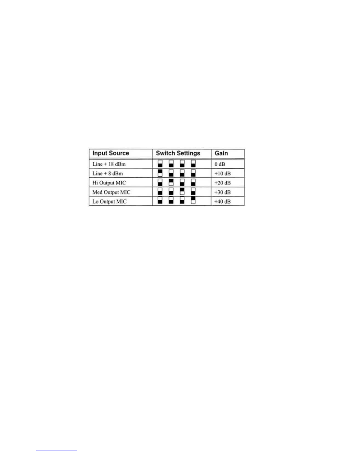
Use Table 6 to assist in setting up the front panel switches on each input module. You will be
setting up:
1. Input Gain: 0, +10, +20, + 30, and +40 dB
2. Input Impedance/Bias Voltage: LOz (600 Ohm), Hiz (10 kOhm) or 48V(at 10 kOhm)
3. Input Ground LIFT or GND
4. Gain
Determine the appropriate input gain for each channel and enter the value in Table 6. Refer to
Figure 17 for the front panel switch settings.
Note: Only one switch should be ON at a time as gain settings are NOT additive.
Table 6: Basic gain settings
Impedance
Determine the need for each channel’s input impedance at 600 Ohm or Hiz. Most systems
operate better in the Hiz mode.
If 48 V phantom power is needed, set the LOz/HIz/48 V switch to 48 V. With 48 V ON, the
impedance is always HIz. The phantom supply is limited to a maximum combined load of 60 mA
per 32 channels, which is about 2 mA per input channel with all channels in use. Source
impedance is 5000 Ohms. When fewer than the 32 loads are used, the current at each input
can be increased, limited by the 5000 ohm source resistance, up to a total of 60 mA for all
active loads. Always set unused phantom power switches to LOz or Hiz to be sure 48 VDC is
not applied where it is not needed.
Grounding - Determine the switch setting for Pin 1
When using 48 V phantom power, the PIN 1 switch on the front panel (Figure 16 on page 18)
must be set to GND. Do not set this to LIFT unless required to eliminate ground loops.
If phantom power is not being used, set this switch to the requirements of the channel’s signal
source. Make the appropriate entries in Table 6.
Double check your table and position each switch.
After your system is fully set up and operating, use the built-in signal generator to check for
adequacy of signal levels or for possible amplitude overload in any part of the audio path.
Page 20
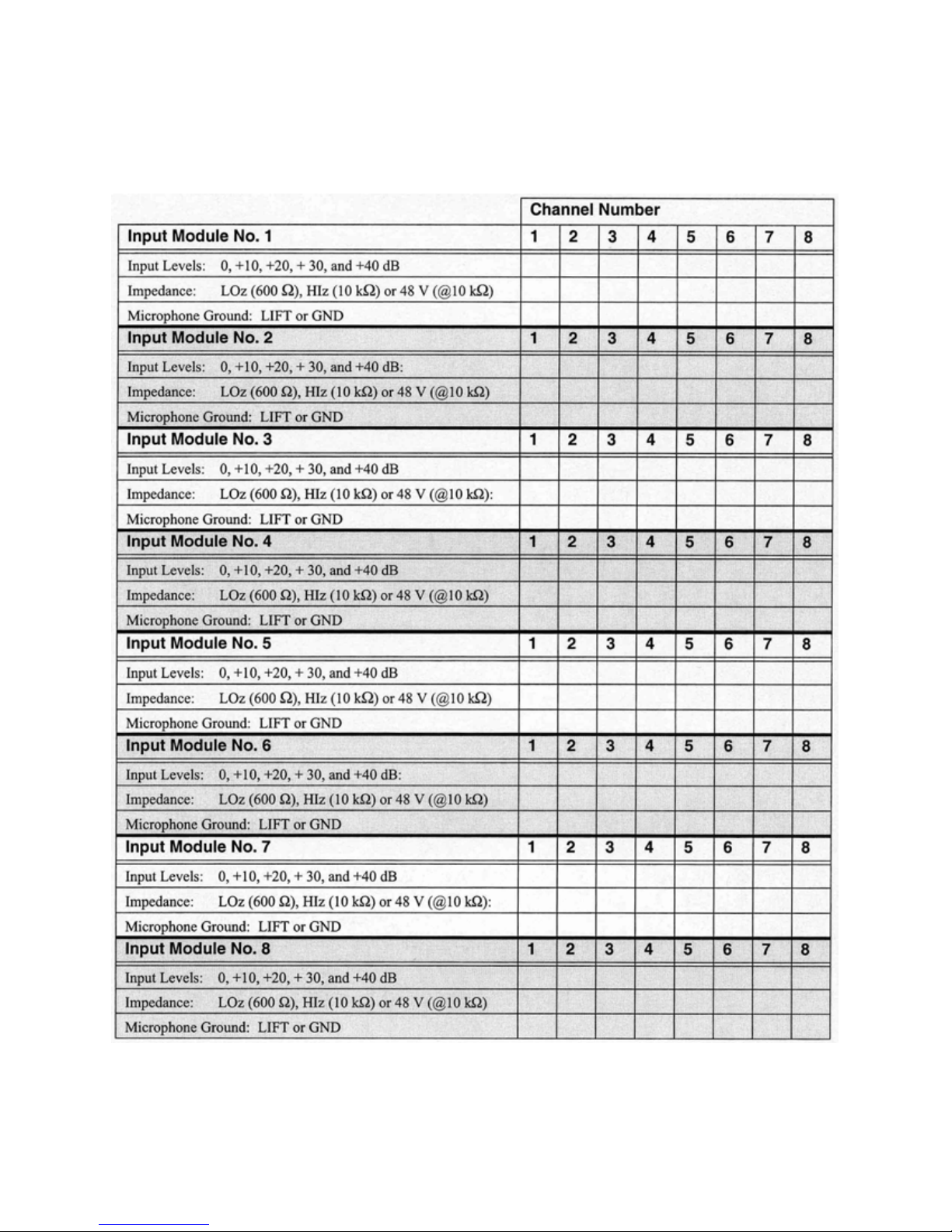
Table 7: Input Module Switch Settings
Page 21
Auxiliary Items
Signal Generator/Monitor
A signal (tone) generator provides a clean output by which any channel and path can be
checked from the audio input right through to the de-multiplexed output at the receiving unit.
Both signal level and frequency are controllable and signal levels are calibrated and displayed
on a scale on the front panel.
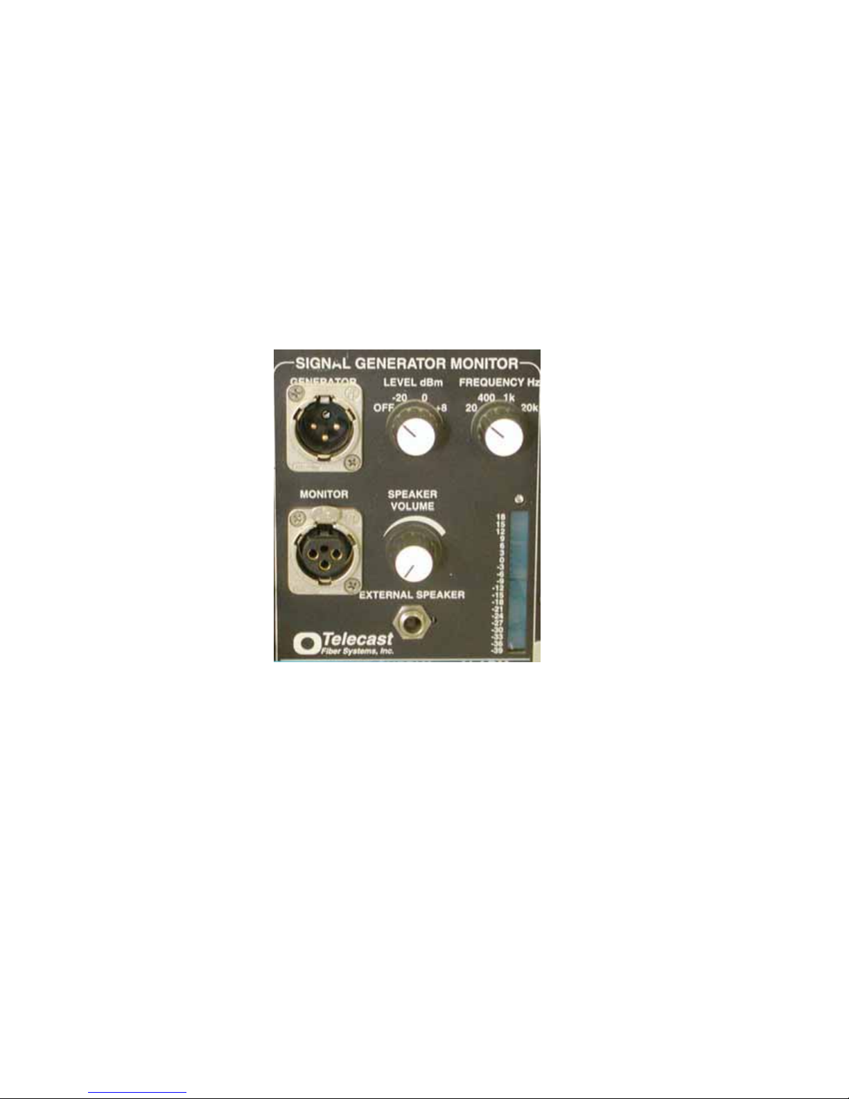
The signal generator provides a convenient means for testing an audio channel. As seen in
Figure 18, the generator has two controls. The LEVEL dBm control sets the power for the
generator/monitor (including speaker and amplifier) to off or sets the levels to one of three
calibrated levels of -20 dBm, 0 dBm or +8 dBm. The second control, FREQUENCY, sets the
output to a choice of four frequencies æ 20 Hz, 400 Hz, 1 kHz, and 20 kHz.
Figure 18: Signal Generator/Monitor
To use the signal generator:
Connect the output labeled GENERATOR by XLR cable to any of the audio input points on an
input module. The Model 162/322 multiplexes that signal, sends it on the fiber, and de-muxes it
at the receiving assembly, which is then output at the same physical location number (row and
number) as the original input.
Connect the output channel by a cable to that unit’s MONITOR input connector. Switch the
LEVEL to any setting other than OFF to enable the power to the monitor circuits. A signal level
is displayed on the level meter. Adjust the volume on the internal loudspeaker to hear the signal
(100 Hz - 10 kHz).
An external loudspeaker or headphones ( 8Ω or more) may be connected to the EXTERNAL
SPEAKER by adjusting the speaker volume knob, as shown in Figure 18.
This monitor scheme can be used with program audio as well as the generated test tone.
Page 22
Status Indicators
LED indicators are located on the assembly front panel and on the input and output modules at
each connector.
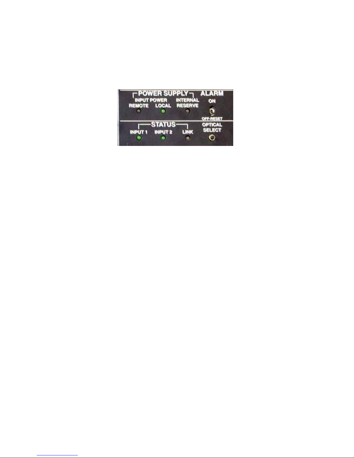
The LEDs on the front panels of the assembly are shown in Figure 19.
Figure 19: Panel Indicators, Signal Status and Power
Power Supply
INPUT POWER
When a data connection (fiber or coax) exists between the local and remote units, the bi-color
REMOTE LED is green if the remote unit’s external power input is good. This indicator turns red
if the external input power to the remote unit fails, or if the data path from the remote unit is lost.
The LOCAL LED is green when the external power input to this unit is present. If the power to
this system fails, the LED turns red.
The INTERNAL RESERVE LED is green when the internal battery is charged. It turns red when
the unit is operating from this battery. Operating time from this battery is limited.
STATUS
When a fiber data connection exists between the local and remote units, the LED corresponding
to the active input will be green. If the coax input is in use, neither INPUT STATUS LED will be
green.
The system will automatically switch to the alternate input if data errors are detected on the
active input. For example, say input Rx1 is the active input and its INPUT 1 STATUS LED
shows green. If the fiber is cut, the INPUT 1 STATUS LED will turn OFF. The system will switch
to input Rx2 and the INPUT 2 STATUS LED will show green. The system will continue to
operate from INPUT 2 as long as the fiber is good.
LINK STATUS is a bi-color LED that indicates the condition of data being received. The LED
shows green when receiving good data and shows red when no data is being received or the
data contains excessive errors. When LINK STATUS is red, the INPUT STATUS LEDs are
gated OFF.
On older Adders, select COAX by the internal switch to enable the COAX input and
corresponding LED. This disables the FIBER inputs and corresponding INPUT LEDs. LINK
STATUS still operates as above. There is no automatic switch between coax and fiber.
Page 23
On Newer Adders, there are no switched to enable coaxial operation. The system runs in COAX
PRIORITY which means that it is “looking” for a coax link first and, if one is not found, then goes
looking for a fiber link.
The OPTICAL SELECT switch toggles between INPUT 1 and INPUT 2, and is useful for testing
whether the fibers are good.
The audible ALARM is controlled by the ALARM ON - OFF/RESET switch. This is a latching
alarm requiring it to be momentarily set to OFF then back to ON to quiet the alarm after it is
triggered. The following conditions are monitored and will trigger an audible alarm when there is
an error and the ALARM switch is in the ON position:
Link Status Always Active
Local Power Defeatable by SW6
Remote Power Defeatable by SW6
2-wire intercom power If the option is installed
Received Signal Level
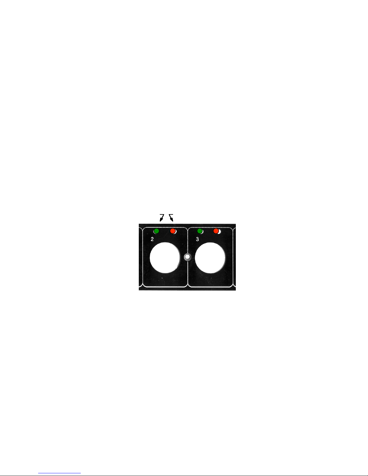
Each channel input or output connector has two LEDs: the left LED is green, and the right LED
is red. Figure 20 shows the LEDs on the output module; location, function and color are the
same on the input module.
RedGreen
Figure 20: Output Module LED Indicators
GREEN indicates that a signal of at least -12 dBm is present at the respective channel.
RED indicates that the signal in the channel is approaching or at the clipping level of +18 dBm.
Reduce the signal level by setting gain switches at the respective channel on the input module.
Page 24
System Interconnections
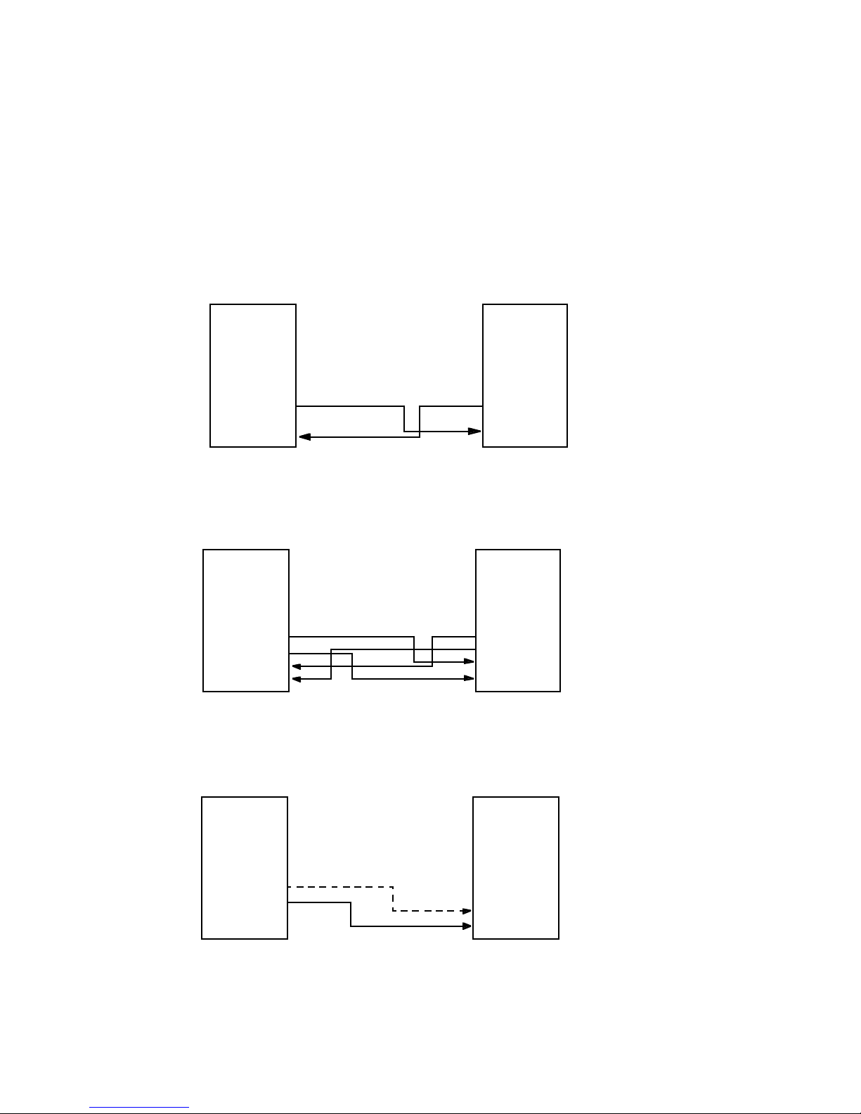
There are four common interconnection configurations for the Model 162/322.
Configuration #1 — Standard Full Duplex Operation
Audio inputs and outputs
Data inputs and outputs
Full intercom
Refer to Figure 21 when wiring for standard operations.
#1
162/322
T
x4
Tx3
Tx2
Tx1
Rx2
Rx1
#2
162/322
Tx4
Tx3
Tx2
Tx1
Rx2
Rx1
Figure 21: Standard 2-Fiber Connection
Configuration #2 — Operation with Fiber Redundancy
Add a second fiber pair. Refer to Figure 22 when wiring operations with fiber redundancy.
#1
162/322
Tx4
Tx3
Tx2
Tx1
Rx2
Rx1
#2
162/322
Tx4
Tx3
Tx2
Tx1
Rx2
Rx1
Figure 22: 4-Fiber Connection for Fiber Redundancy
Configuration #3 — Unidirectional Operation
Refer to Figure 23 when wiring for unidirectional operations.
#1
162/322
In
Only
Tx4
Tx3
T24
Tx1
Rx2
Rx1
Figure 23: Unidirectional Fiber Connections
Configuration #4 — Operation using the Wavelength Division Multiplexer
#2
162/322
Tx4
Tx3
Tx2
Tx1
Rx2
Rx1
Out
Only
Page 25
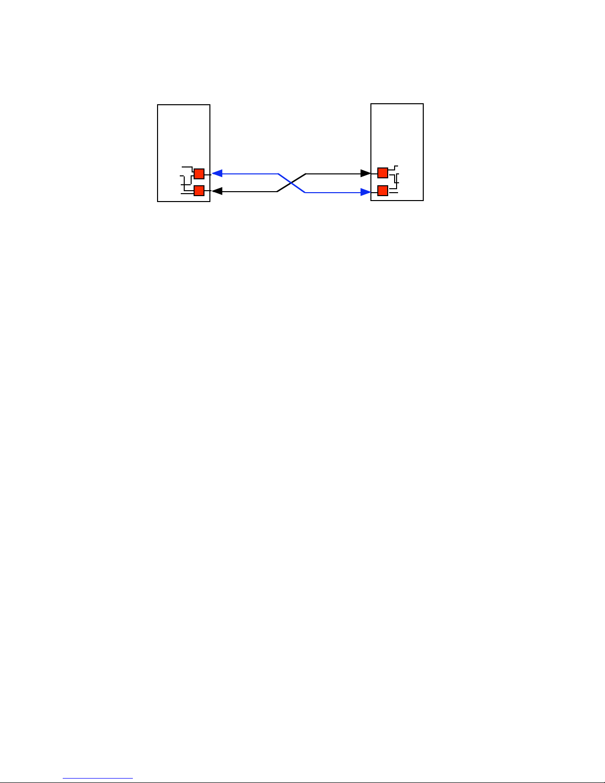
Refer to Figure 24 when wiring for operations using the WDM.
#1
162/322
Tx4
Tx3
Tx2
Tx1
Rx2
Rx1
Optional path
Primary path
#2
162/322
Tx4
Tx3
Tx2
Tx1
Rx2
Rx1
Figure 24: Fiber Connections using WDM
Powering Up
Never try to move the power switch on any front panel without first disengaging its lock by
pulling on the switch lever.
With power OFF at both units, check all electrical and optical connections as described under
Installation of the Assembly on page 3. Firmly seat all connectors.
To operate the power switch:
1. Pull the lever away from the panel.
2. Move it up for power ON, or down for power OFF.
3. Switch ON the power to all Adder 162/322 units.
The power switches at all connected units must be ON for the system to function normally.
Verify that:
1. Green external power LEDs are illuminated.
2. link status LED is green if the fibers are connected.
3. input 1 or input 2 LEDs are green, one at a time.
If you do not get this result, refer to Troubleshooting on page 37.
You may connect or disconnect any optical, audio, data, or intercom plug while the power is on.
If an optical fiber port is not in use, be sure that it is covered.
Page 26
Intercom Modules
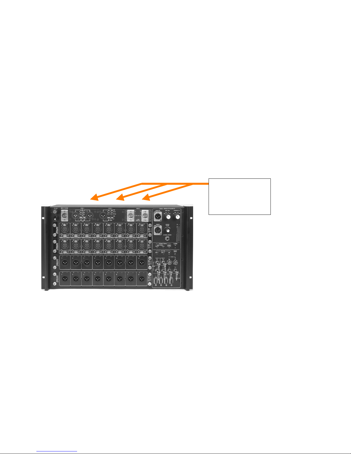
Up to three dual-channel intercom modules can be installed in the Adder 162/322. Three types
of intercom modules are available from Telecast:
1. Balanced 4-wire
2. Clear-Com 2-wire
3. RTS/Telex compatible 2-wire
Intercom modules are located at the top of the assembly in the Model 162 and along the right
side on Model 322 as shown in Figure 25. Modules are designated COM1, COM2 and COM3 as
seen in Figures 25 and 26.
INTERCOM
LOCATIONS
FOR 162
Figures 25: Model 162 Intercom Locations
Page 27
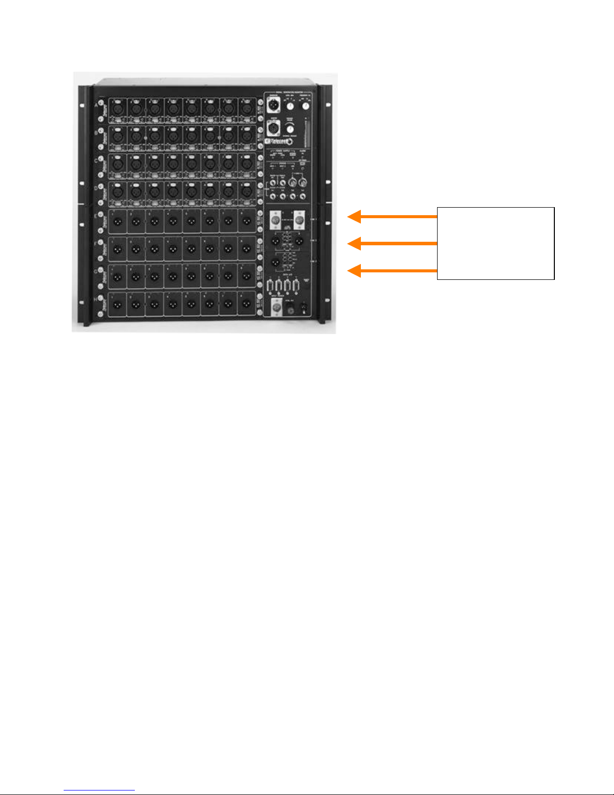
INTERCOM
LOCATIONS
FOR 322
Figures 26: Model 322 Intercom Locations
Intercoms can be of any type in any location in the assembly. However, for proper operation of
the intercom channel, the same placement order must be followed at any other assembly at the
other side of the system.
A 2-wire system can be interconnected with a 4-wire system at another Adder 162/322, but not
all intercom functions will work (for example, calling).
If an optical split output is used to connect fiber to additional receiving locations, the intercom
signals will be present at the receiver, but transmission back to the originating unit will not be
possible.
Intercom Connections
4-wire (balanced)
4-wire Auxiliary (balanced) intercoms use an individual 5-pin XLR on each of the two channels
in each module. Refer to Figure 27. XLR pin functions are given in Table 7. Intercom Module
Gain is 0 dB.
NOTE: 50 dB of gain may be added to 4-wire module inputs by DIP switches on the mother
board for MIC applications. See Intercom Setup Switches on page 26.
Page 28
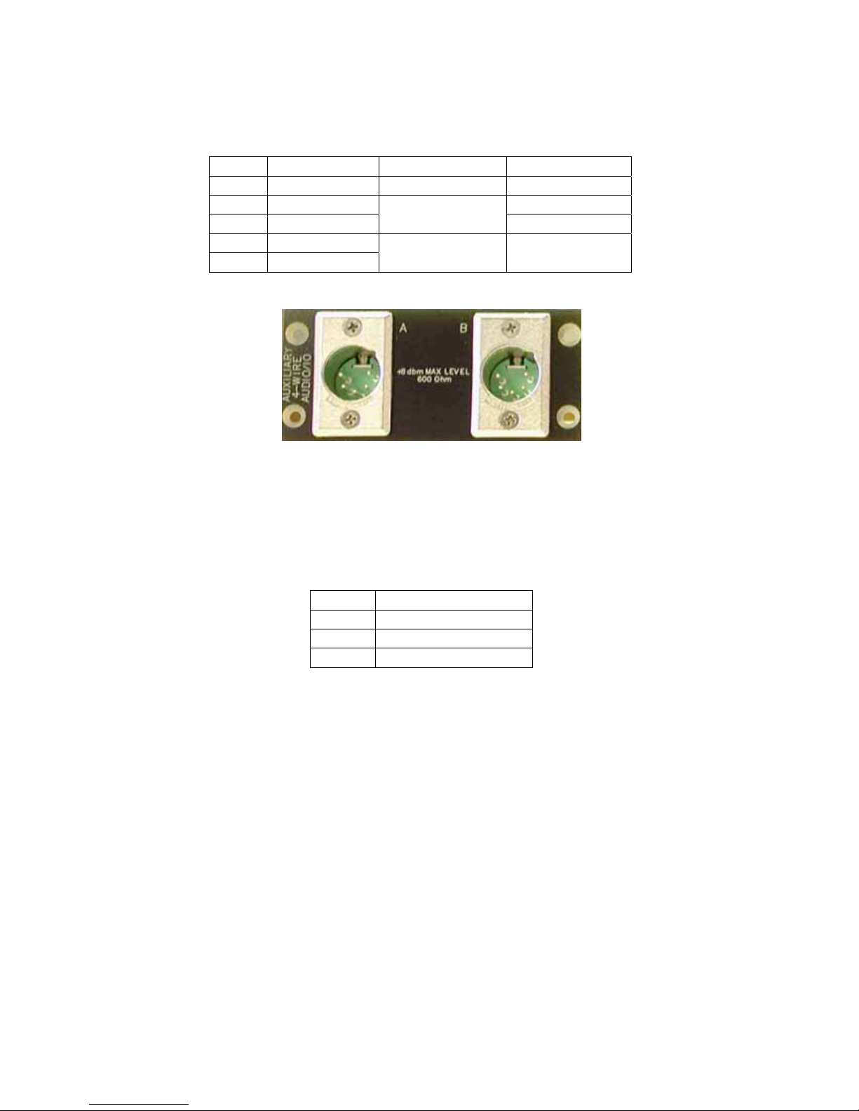
Table 7: 4-Wire Intercom Connections
PIN FUNCTION IMPEDENCE SIGNALS
1 Ground
2 Input (+) Line: +8 dBm
3 Input (-)
4 Out (+)
5 Out (-)
600 Ohm input
>=600 Ohm
load
Mic: -32 dBm
+8 dBm
Figure 27: Intercom Module: 4-Wire Auxiliary (balanced)
Clear-Com
Clear-Com intercom modules have a 3-pin XLR connector for each of the A and B channels.
This Telecast module fully supports the Clear-Com signaling protocol and signal levels.
The Clear-Com Intercom Connections are listed in Table 8.
Table 8: Clear-Com Intercom Connections
PIN FUNCTION
1 Ground
2 +VDC Power
3 Power
Note: When using the Clear-Com external power supply, pin 3 termination must be lifted on the
power supply to prevent motor-boating.
Clear-Com channel operation is optimized by the use of the front panel adjustments shown in
Figure 28 and listed below:
• Input Gain, ±10 dB
• Output Gain, ±10 dB
• Null
Switches are also provided for the channel pair for:
• Dry unpowered (d), or Wet powered (w) PORTS
• 200 Ohm on or off terminations TERM
Page 29
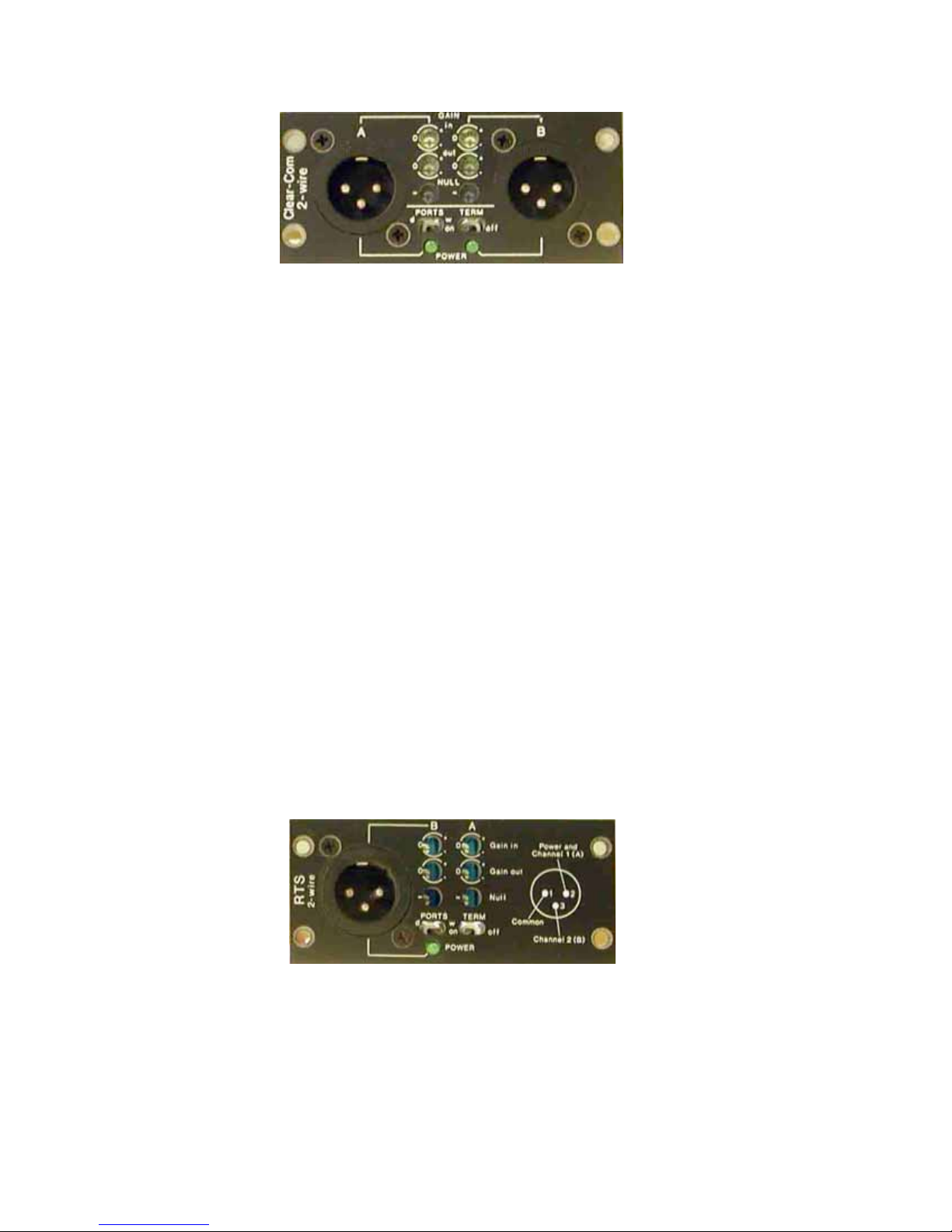
Figure 28: Intercom Module: Clear-Com
The Telecast Clear-Com interface is compatible with powered or unpowered belt packs as well
as fixed equipment. You may power 5 to10 belt packs with each intercom module from the
internal power supply. Many more belt packs can be added if powered externally. Refer to your
intercom manufacturer’s documentation for additional system details.
For operation with a belt pack, set the PORTS to w (powered), the TERM to ON and center
each of the INPUT gain, OUTPUT gain and NULL controls. Readjust these controls to optimize
performance as required.
RTS Telex
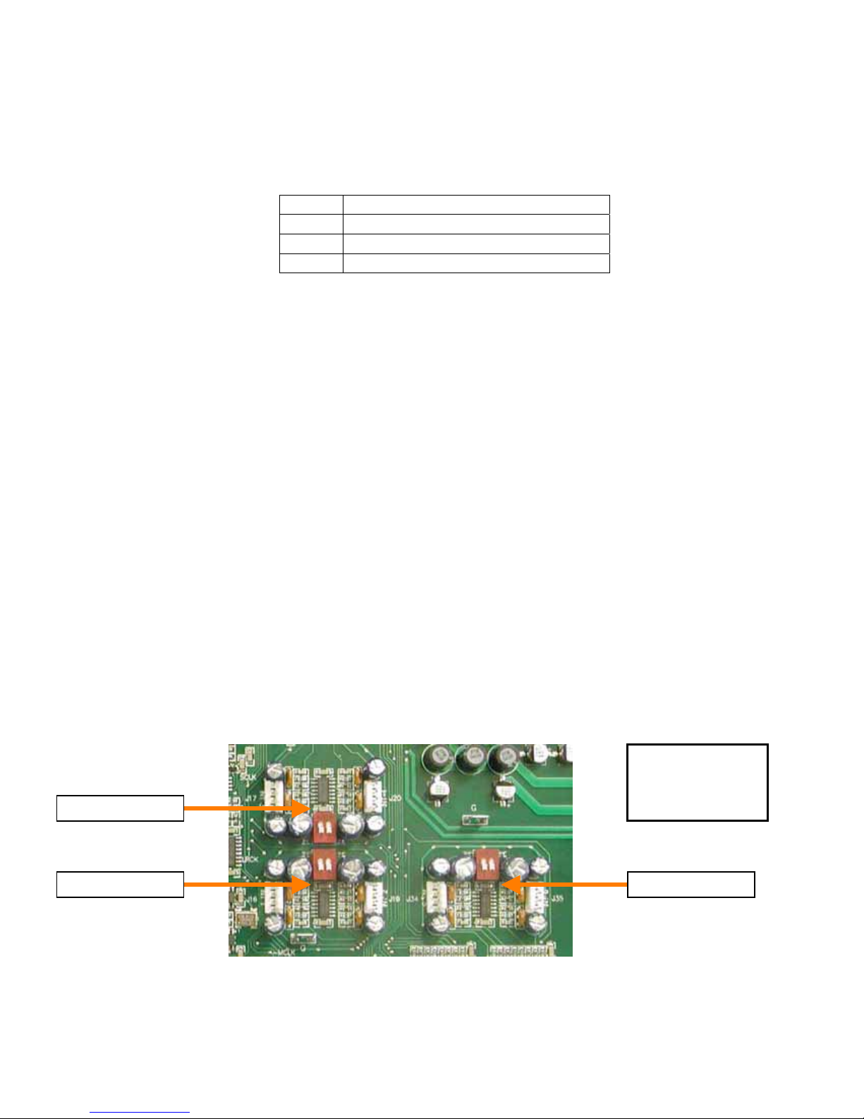
RTS modules provide a two-channel intercom on a single 3-pin XLR connector. This Telecast
module fully supports the RTS signaling protocol and signal levels.
RTS channel operation is optimized by the use of front panel adjustments as shown in Figure 29
and listed below.
• Input Gain, ± 10 dB
• Output Gain, ± 10 dB
• Null
Table 9 lists the RTS Telex pin numbers and intercom connections. Switches are also provided
for the channel pair for:
• Dry unpowered (d), or Wet powered (w) PORTS
• 200 Ohm ON or OFF terminations TERM
Figure 29: Intercom Module: RTS Telex
The interface is compatible with powered or unpowered belt packs as well as fixed equipment.
You may power 5 to 10 belt packs with each intercom module. Refer to the note on page 23 and
to your intercom manufacturer’s documentation for additional system details.
Page 30
For operation with a belt pack, set the PORTS to w (powered), the TERM to ON and center
each of the INPUT gain, OUTPUT gain and NULL controls. Readjust these controls to optimize
performance as required.
Table 9: RTS Telex Intercom Connections
PIN FUNCTION
1 Ground
2 +VDC power & Chan 1 Audio
3 Chan 2 Audio
Intercom Module Replacement
Intercom modules (up to three) within the Adder 162/322 are installed by Telecast in
accordance with your purchase order. Should you want to change or add modules, you may
have to reset certain switches on the Main PC Board of the Adder 162/322 assembly.
Cable Harness
A multi-conductor harnessed cable built into the Adder 162/322 runs behind the module
locations. This cable connects the module to power and signal sources. There is a AMP-MTA
type connector for each module on this harness; the connector fits all module types.
Intercom Setup Switches
For Four-Wire Intercoms, three 2-unit slide switches on the Main PC Board inside the assembly
may have to be reset depending on the choice of input level. Switch settings relate to the MIC
or LINE input levels.
A few audio modules will have to be removed from the assembly to gain access to these
switches. Refer to Figure 8 on page 14. The switches are detailed in Figure 30.
Channels A and B within modules 1, 2, and 3 shown in Figure 25 on page 26 are configured on
the Main PC Board by SW3 (channels 1,2), SW4 (channels 3,4), and SW5 (channels 5,6),
respectively, in Figure 30.
Switch
UP = mic
DOWN = line
Figure 30: Intercom MIC - LINE Switches
Page 31

To change an intercom module in the assembly:
1. Turn the power OFF.
2. Remove the screws that hold the module to be replaced.
3. Remove the Input and Output modules at locations 3 and 4 from the bottom of the
assembly to gain access to the Main PC Board (see Removing and Replacing
Modules on page 15).
4. Check that the intercom switch settings are appropriate for the new module to be
inserted.
5. Connect the multi-conductor cable to the respective intercom module.
5. Set the module in place and fasten the mounting screws. Replace the Input and
Output modules.
6. Turn the power ON.
Page 32
Theory of Operation
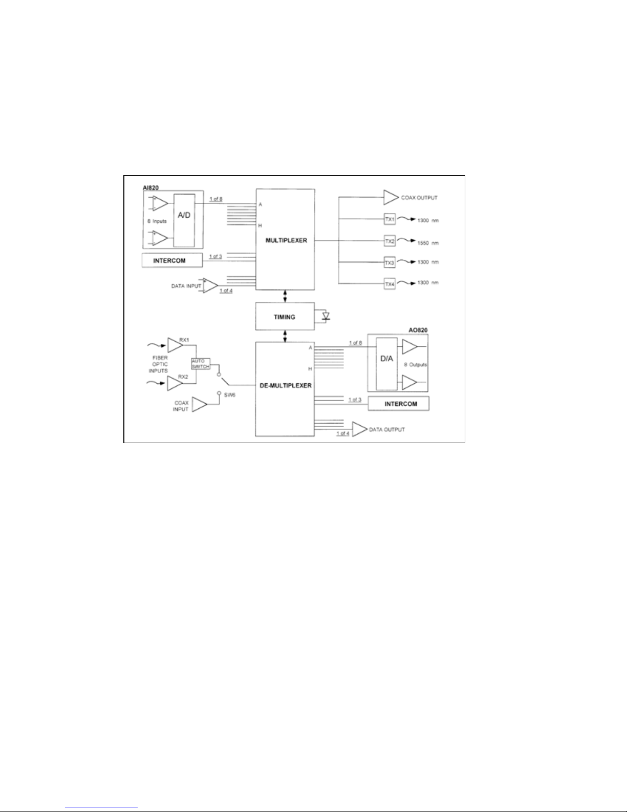
The Adder 162/322 circuit block diagram shown in Figure 31 is a representative system with
one 8-channel module in each unit. The Adder 162/322 operating as a transmitter accepts up to
32/64 audio inputs and up to four digital inputs. Time division multiplexes them onto a single
optical fiber or coaxial cable.
Figure 31: Electronic Block Diagram
Demultiplexed signals are fed to corresponding output connectors on an output module. 2
Coaxial cables may be optionally used instead of fiber optic cable. However, redundant coaxial
cable operation is not available. All signals on the fiber or coaxial cable are digital, and therefore
relatively insensitive to transmission level variations.
Data Connectors 1 and 2
The digital input buffer circuit accepts both data signals (RS-232, RS-422) and contact closures
and delivers this information to the multiplexer. The closure handling portion of the circuit
accepts information only from D-subminiature data connectors 1 and 2. Refer to Figure 32.
The circuit accepts a contact closure indicated by the switching of pin 8 to ground level pin 3.
This can also be accomplished by a TTL connection closure with pin 3 as the ground reference.
The digital output buffer circuit accepts the demultiplexed data and contact closure signals and
provides them at appropriate levels to the D-subminiature data connectors. Refer to Figure 33.
The output closure output is via an SPST-NO 1 FORM A relay; this closure is isolated and not
ground referenced.
Page 33
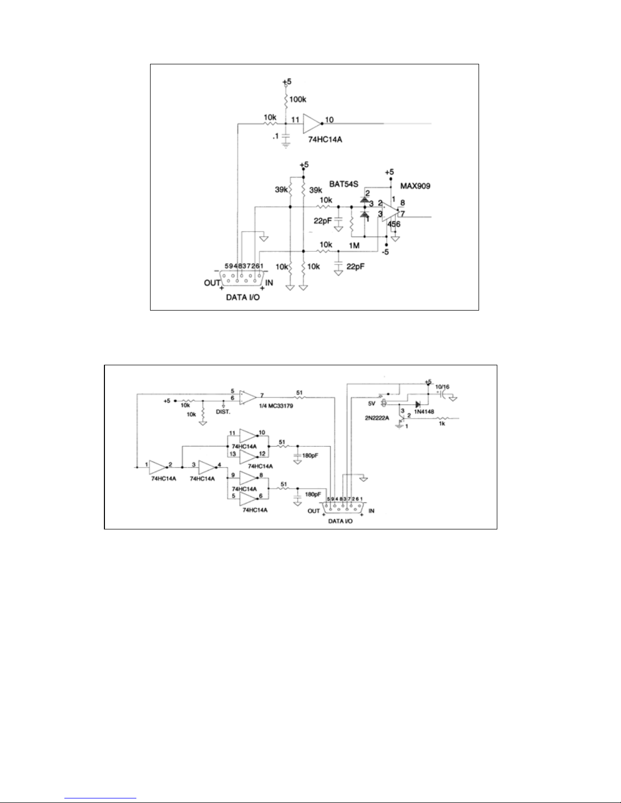
Figure 32: DATA and Relay Digital Input Circuit
Figure 33: Digital Data Output Circuit
Audio Circuits - Output
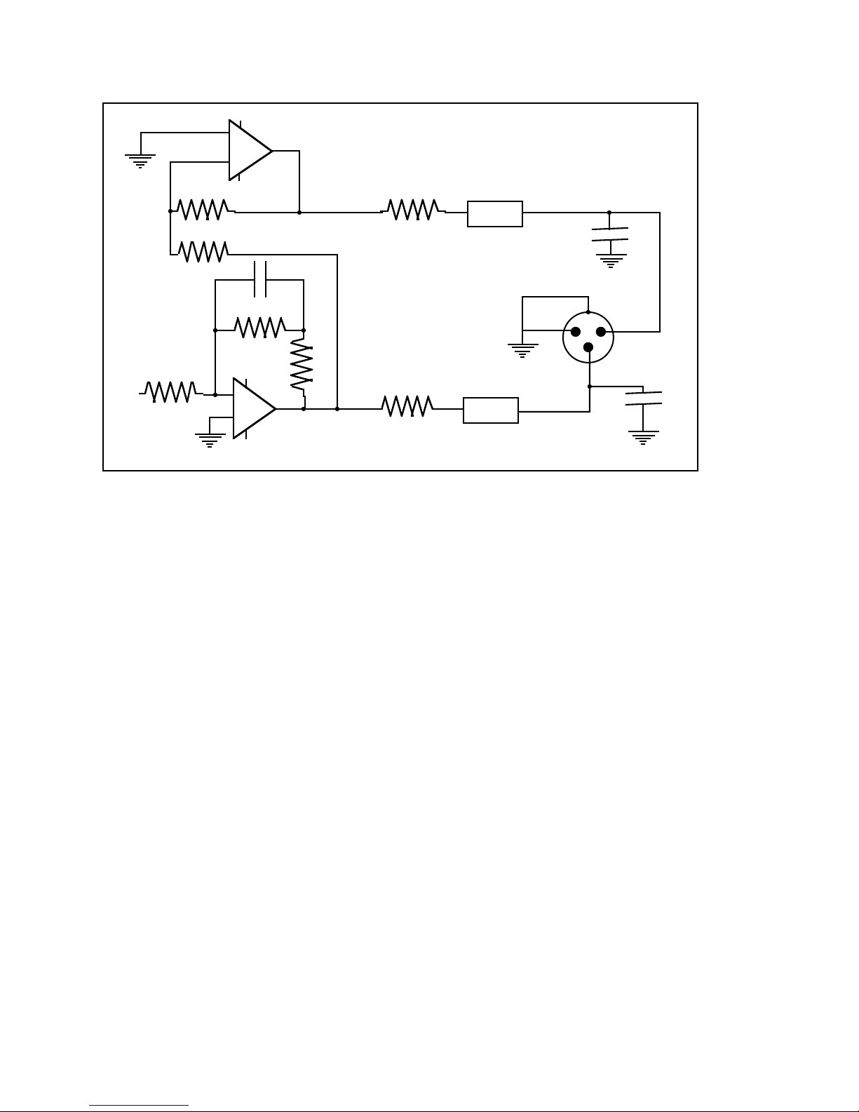
The audio output circuit is shown in Figure 34. The output impedance between pin 2 and 3 is
30 Ohm, balanced. Output characteristics are given in the Intercom Interface section.
Page 34
10
MC33179
.015 Film
4.99kΩ
MC33179
8
15Ω
2kΩ
7
Figure 34: Audio Output Circuit
15Ω
1
1
Ferrite
Bead
Ferrite
Bead
2
1
2
100pF
0
2
3
100pF
9
2kΩ
2kΩ
2kΩ
6
5
Unbalanced operation is possible by using pins 1 and 3. Do NOT short pin 2 or 3 to ground or
severe distortion will result.
Audio Circuits - Input
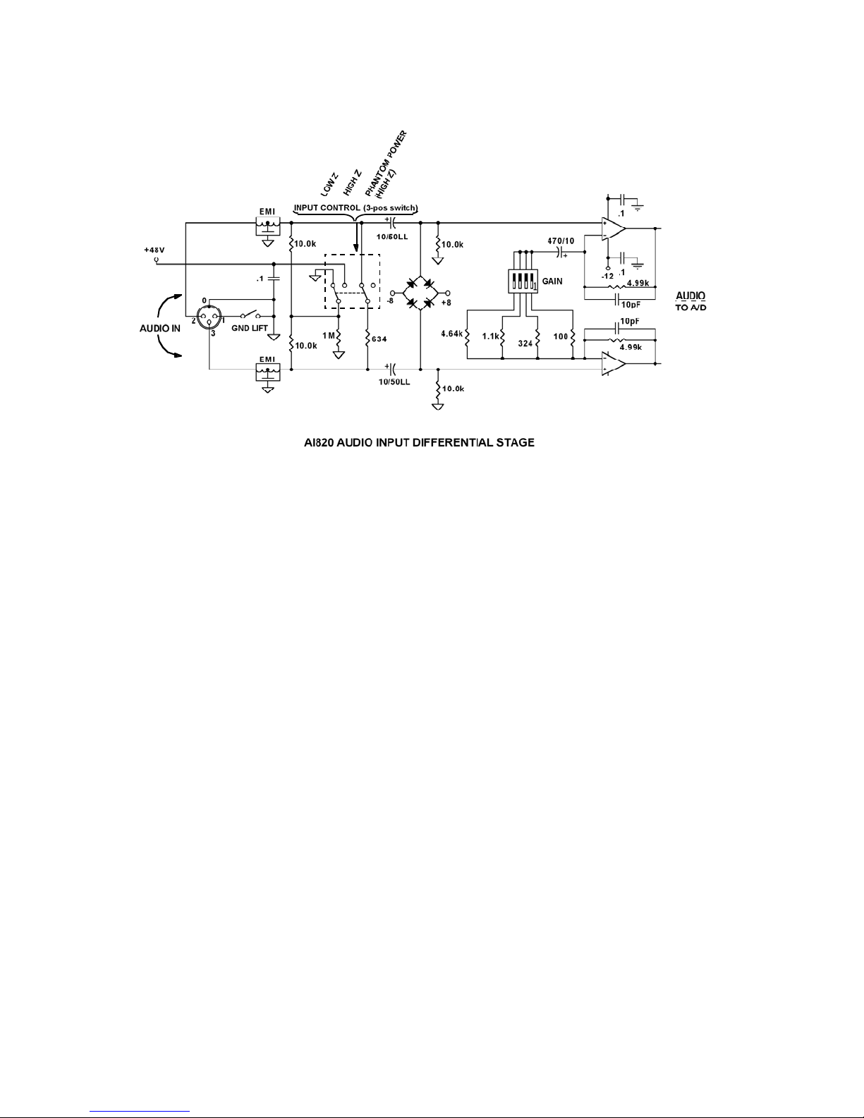
The audio input circuit can be set to have a balanced impedance of 600 Ohm or 10 kOhm. The
audio input circuit can accept a wide range of signal levels by the use of scaling DIP switches
on the input module front panel and also supply 48 VDC for condenser microphone bias; see
Figure 35. Refer to Specifications on page 38 for details.
Page 35
+12 VDC
Figure 35: Audio Input Schematic
The main circuits in the Adder 162/322 are described in Table 10.
Table 10: Adder 162/322 Main Circuits
A/D Input High speed A to D converters located in each audio channel.
Multiplexer, Input Sequentially presents four RS-232/422 digital inputs, two contact
closures and up to 64 digitized audio signals from the A/D
converters to the optical output driver.
Demultiplexer, Output Takes sequential digital signals from the pin diode and separates
them: up to 64 to the D/A converters, four to the RS-422
transmitters and two to the contact closure relays.
D/A, Output High speed digital to analog converters located in each audio
channel convert the digitized signal back to analog audio.
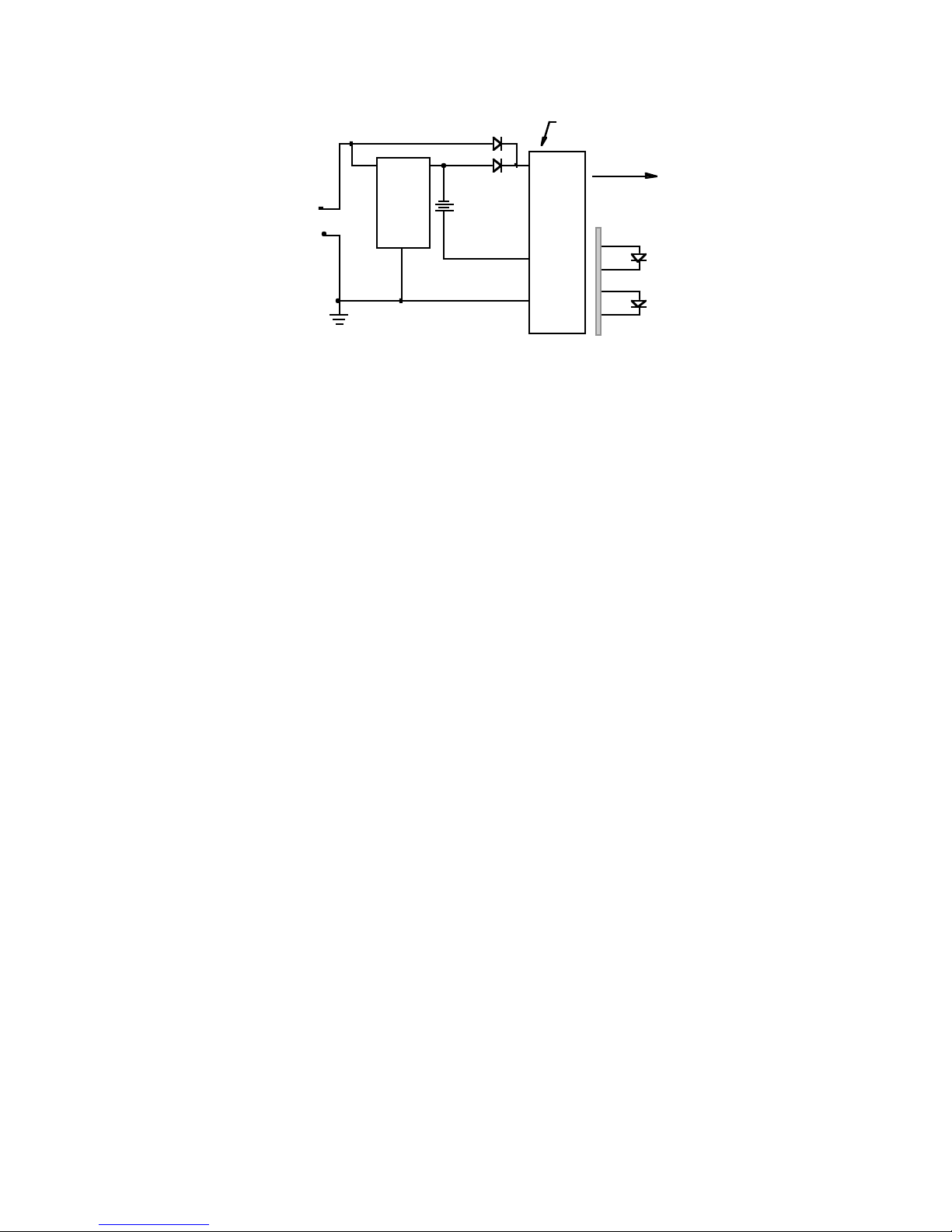
Battery charger, Model 162/322 Assembly The battery charger (see Figure 36 on page 36) is
active whenever an Adder 162/322 unit is receiving DC power
between 13.8 and 18 VDC. Charging current is limited to a trickle
level at any voltage input. Full charge takes 16 hours.
Page 36
Front Panel
Power Switch
Switch
Mode
Power
Power to
Electronics
Front
Panel
External
Power
LED
Internal
Reserve
LED
+13.8 VDC to +18 VDC
Front Panel,
Power
Connector
DC INPUT
4
1
Charge
Control
Circuit
Internal
Battery
Figure 36: Battery Charger Block Diagram
The optical output is generated from a high power Lased Diode coupled to the fiber. User
connections are made at a bulkhead type ST connector on the front panel of the assembly.
Transmission cable must be matched to the fiber pigtail type specified at the time of
manufacture.
The input uses a PIN Photodiode and amplifier to convert the optical signal back into an
electrical signal.
Preventive Maintenance
A high capacity Ni-Cad rechargeable battery pack is mounted to the top cover for easy
accessibility. Replace this battery pack approximately every two years or as required.
Replacement battery packs are available from Telecast. Dispose of batteries in accordance with
local regulations.
1. Move the power switch to OFF.
2. Remove the ten screws holding the top cover.
3. Remove the four screws holding the battery bracket.
4. Disconnect the battery and replace it.
5. Replace the bracket and cover.
The battery is connected to the main system board via a polarized 2-pin connector, and is
secured by a bracket and four screws.
With a full charge, this battery will operate Model 162 for 30 minutes and Model 322 for 15
minutes. Operation time varies with module complement in the assembly.
Accessory List
The following accessories are available from Telecast:
1. Optical power meter kit
2. Cable repair kit with Quick-crimp kit to attach ST connectors to fiber optic cable
3. Loop-back cable to localize signals during installation test
4. Prefabricated cables built to custom lengths
Page 37
Troubleshooting
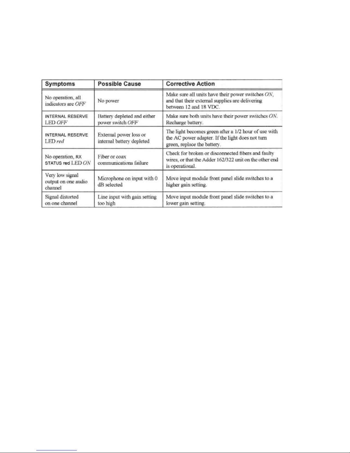
Troubleshooting Chart
Measuring Optical Power
The optical fibers couple power from the transmitters to the receivers. Operation of this system
hinges on the correct optical power levels. These levels can be measured with an OPTICAL
POWER METER such as the Telecast model PMTR-ST-3W or equivalent. The power meter is
calibrated in units of dBm, or power referenced to 1 milliwatt expressed in dB where 0 dBm is 1
milliwatt and -30 dBm is 1 microwatt.
To determine the transmitter output, use a short cable terminated with the appropriate
connectors, generally ST-style to connect the power meter to the transmitter output. Set the
meter to the same wavelength as the transmitter. The meter should show a power level greater
than -10 dBm.
Once the complete cable is installed and connected, measure the power at the receiver inputs.
Remove the connector from the receiver input. If the system is operating an ALARM may
occur. Connect the cable to the power meter. The measured power should be in the range of
–10 to -26 dBm.
To insure reliable system operation, a system margin must be maintained. Telecast
recommends a minimum margin of 3 dB or more. To insure this margin, the power measured at
the receiver must be in the range of -10 to -23 dBm preferred.
Page 38

Specifications
System Characteristics
Transmission Method Digital Time Division Multiplexing (TDM) System
Aggregate Data Rate 147.5 Mbps
Audio Characteristics
Modules 8 Channel INPUT (AI820) or
8 Channel OUTPUT (AO820)
Number of Modules
Model 162 4 (32 total channels); any combination
Model 322 8 (32 total channels); any combination
Analog to Digital Conversion 24 bit delta sigma
Sample Rate 48 ksamples/sec
Amplitude Frequency response
@ +8 dBm 20Hz to 20kHz +/- 2db
Total Harmonic Distortion
@ +8 dBm, 20-20kHz <0.05%
@ +8 dBm, 1kHz <0.01%
Intermodulation Distortion(SMPTE)
@ +8 dBm 60Hz +3kHz mixed 4:1 < 0.04%
Signal to Noise ratio (A-weighted)
20-20kHz; re: +18dBm >102db
Throughput delay ~1millisecond PLUS
5 microseconds per km of fiber or
1.5 microseconds per 1000 feet
Interchannel Phase Delay <1 degree at 1kHz
AI820 Characteristics
Connector Female 3-pin XLR
Input Impedence 600 or 10kOhm, balanced (switchable)
Maximum Input Signal Levels
600Ohm Balanced (Lo Z)
Unity gain +18 dBm peak
+10 dB +8 dBm peak
+20 dB -2 dBm peak
+30 dB -12 dBm peak
+40 dB -22 dBm peak
10kOhm Balanced (Hi Z)
Unity gain +16 dBV peak
+10 dB +6 dBV peak
+20 dB -4 dBV peak
+30 dB -14 dBV peak
+40 dB -24 dBV peak
Page 39

AI820 Characteristics
Connector Male 3-pin XLR
Output Impedence 30 Ohm Balanced
Maximum Output level +18 dBm @ 1kHz, 600 Ohm
Intercom Characteristics
Total Intercom Channels 6
Compatibility (each of 3 modules)
4-Wire (std) (2) Balanced, non-powered, 5-Pin Male XLR
Switchable MIC/LINE input, line output only
ClearCom (Option) (2) Unbalanced powered, 3-Pin Male XLR
RTS (Option) (1) Unbalanced dual-channel, 3-Pin Male XLR
Signal to Noise Ratio (A-weighted) >90 db
Frequency Response @ +8 dBm
80Hz-20kHz +1/-3 dB
Digital Characteristics
Connector (4) 9-pin Female “D” (Telecast Pinout)
Data Channels (1) channel per connector, (4) total
Maximum Data Rate
RS-442 > 150,000 bps
RS-232 > 20,000 bps
Jitter < 330 ns (3.07 MS/s)
Throughput Delay ~ 0.90 microseconds plus
5 microseconds per km of fiber or
1.5 microseconds per 1000 feet
Contact Closure (Tally)
Input TTL 1 or open circuit (remote contact open)
TTL 0 or shorted to circuit ground (remote contact closed)
Output (Form 1A SPST-NO isolated contacts)
Switch Voltage Rating 50 VAC/DC
Switch Current Rating 0.5 Amps
Maximum Carry Current 0.5 Amps
Contact Resistance < 0.5 Ohm
Page 40

Mechanical/Electrical 162 322
Dimensions (W x L x D) 10 x 16.75 (19) x 6 in 17.5 x 16.75 (19) x 6 in
25.4 x 42.5 x 15.2 cm 44.5 x 42.5 x 15.2 cm
Weight 15 pounds (6.8 kg) 22 pounds (9.8 kg)
Power Requirements
Current 3.0 Amps maximum 4.5 Amps maximum
Power 30 watts maximum 45 watts maximum
Thermal 100 BTUs maximum 150 BTUs maximum
External Input Voltage 15 VDC nominal, 10-18 VDC operating
Operating Temperature Range - 40 to + 60 °C
Operating Humidity Range 10-90%, non-condensation
Optical Characteristics
Transmit Optical Wavelength
Tx1, Tx3, Tx4 1300 nm
Tx2 1550 nm
Optical Connectors ST compatible
Two fiber system (standard) MM SM
Minimum Transmit Power - 10 dBm - 10 dBm
Minimum Receiver Power - 28 dBm - 28 dBm
Available Loss Margin 18 dB 18 dB
One fiber system (WDM option) MM (LW1 option) SM (SW1 option)
Minimum Transmit Power - 12 dBm - 12 dBm
Minimum Receiver Power - 26 dBm - 26 dBm
Available Loss Margin 14 dB 14 dB
Fiber Optic Distance Limits 10 km 20 km
(within available optical loss margin) 30,000 feet 60,000 feet
Coax Characteristics
Impedance 75 Ohm
Recommended Cable Type Belden 8281
Connectors BNC
Distance Limits 305 meters (1,000 feet)
Repair
If unable to resolve the problems with your Adder 162 or 322 System, call Telecast Fiber
Systems, Inc. for assistance at 508-754-4858 and ask for our service department. To return a
unit for repair, you must obtain a return material authorization (RMA) number from Telecast.
Page 41

Warranty
LIMITED WARRANTY STATEMENT
Telecast Fiber Systems, Inc. (“Telecast”) expressly warrants to Buyer that the Products supplied shall be free from
defects in materials and workmanship for a period of 12 months following the date the Products are delivered to
Buyer (the “Warranty Period”). Telecast's liability under this limited warranty shall be limited, at its option, to providing
refund of purchase price for Products, or replacing or repairing Products shown to be defective either in materials or
workmanship. Buyer's sole and exclusive remedy for breach of warranty shall be such refund, replacement or repair.
A claim of defect in materials or workmanship in any Product shall be allowed only when it is submitted in writing to
Telecast Fiber Systems, Inc. within seven days after discovery of the defect, and in any event within the Warranty
Period. No claim shall be allowed in respect of any Product which has been altered, neglected, damaged or stored in
any manner which adversely affects it. In order to obtain service under the terms of this warranty, Distributor’s
customer or Distributor must notify Telecast of the defect prior to the expiration of the applicable warranty period and
obtain a Return Authorization Number from Telecast. In no event may products be returned to Telecast or to
Distributor for warranty service without having obtained from Telecast a Return Authorization Number.
This limited warranty applies only to new and unused Products delivered to Buyers located within the United States of
America, or to international Buyers if sold through an authorized Distributor organization, and shall not extend to any
equipment not manufactured by Telecast Fiber Systems, Inc., even though such equipment may be sold or operated
with the Products. In addition, this limited warranty shall be void and of no further force or effect whatsoever if the
Product is repaired or modified by any person other than an authorized representative of Telecast Fiber Systems, Inc.
without the consent of Telecast Fiber Systems, Inc. This warranty shall not apply to any defect, failure or damage
caused by improper use or inadequate maintenance and care. Nor shall this warranty apply to any damage caused in
whole or in part by attempts by personnel other than Telecast’s personnel, as approved in advance in accordance
with the foregoing provisions, to open, install, repair, or service the Product; nor to damage resulting from improper
connection with incompatible equipment; nor to damage to a unit which has been modified by personnel other than
Telecast personnel.
Products returned to Telecast for warranty service shall be shipped, freight prepaid to Telecast. Telecast will return
the repaired product or ship a replacement, freight prepaid, to either Distributor or Distributor’s customer, as
requested by Distributor’s customer, at a location within the United States or, at Telecast’s option, to Distributor’s
location in the case of international sales.
This limited warranty shall also apply to Products that replace defective Products and Products that have been
repaired by authorized representatives of Telecast Fiber Systems, Inc., but only for the original Warranty Period. The
Warranty Period shall not be extended by reason of defect, or any period of time during which the Product is not
available to Buyer because of defects or repairs, without the express written consent of Telecast Fiber Systems, Inc.
EXCEPT FOR THE EXPRESS LIMITED WARRANTY AGAINST DEFECTS IN MATERIALS AND
WORKMANSHIP CONTAINED HEREIN, TELECAST FIBER SYSTEMS, INC. MAKES NO WARRANTY
OF ANY KIND WHATSOEVER, EXPRESS OR IMPLIED, AND ALL WARRANTIES OF
MERCHANTABILITY, FITNESS FOR A PARTICULAR PURPOSE, AND OTHER WARRANTIES OF
WHATEVER KIND ARE HEREBY DISCLAIMED BY TELECAST FIBER SYSTEMS, INC. THIS LIMITED
WARRANTY SETS FORTH EXCLUSIVELY ALL OF TELECAST FIBER SYSTEMS, INC.'S LIABILITY IN
CONTRACT OR OTHERWISE IN THE EVENT OF A DEFECTIVE PRODUCT.
WITHOUT LIMITATION ON THE FOREGOING, TELECAST FIBER SYSTEMS, INC. EXPRESSLY
DISCLAIMS ANY LIABILITY WHATSOEVER FOR ANY DAMAGES INCURRED DIRECTLY OR
INDIRECTLY IN CONNECTION WITH THE SALE OR USE OF, OR OTHERWISE IN CONNECTION
WITH, THE PRODUCT, INCLUDING WITHOUT LIMITATION, LOSS OF PROFITS AND SPECIAL,
INCIDENTAL OR CONSEQUENTIAL DAMAGES, WHETHER CAUSED BY NEGLIGENCE OR
OTHERWISE, REGARDLESS WHETHER TELECAST HAS BEEN GIVEN ADVANCE NOTICE OF THE
POSSIBILITY THEREOF.
THIS WARRANTY IS GIVEN BY TELECAST IN LIEU OF ANY OTHER WARRANTY EXPRESSED OR
IMPLIED.
 Loading...