

Reference Manual
Model CFA-24
Transparent Cable Farm
Automation Switch
Rev –
Version 7.7.1
Date of Publication: 02/22/2019
“Results You Can Count On”

Model CFA-24 Transparent Cable Farm Automation Switch Reference Manual TOC 1
Table of Contents
1.0 Introduction ......................................................................................................................................................... 1
1.1 Overview ......................................................................................................................................................... 1
1.2 Main Features .................................................................................................................................................. 3
1.3 Specifications .................................................................................................................................................. 4
2.0 About This Manual .............................................................................................................................................. 5
2.1 Chronological Order of Processes ................................................................................................................... 5
3.0 Before You Begin ................................................................................................................................................ 6
3.1 Establish CFA Network .................................................................................................................................. 6
3.2 Connecting Standalone CFA-24 to POE Adaptor ........................................................................................... 6
3.3 Connecting CFA-24 to POE Switch ............................................................................................................... 7
3.4 Changing Factory Default IP Address ............................................................................................................ 8
3.5 Proper Shut Down Procedure (for Systems purchased before 1/1/2016) ...................................................... 10
3.6 Reset Switch .................................................................................................................................................. 12
4.0 Definitions ......................................................................................................................................................... 13
4.1 Loop Segment ............................................................................................................................................... 14
4.2 Punch Down Block ....................................................................................................................................... 16
4.3 Input/Output Connectors ............................................................................................................................... 16
4.3.1 CPE Input/Output Connector .................................................................................................................... 16
4.3.2 CO Input/Output Connector ..................................................................................................................... 16
4.3.3 Custom Cable Set Example ...................................................................................................................... 17
4.3.4 Cabling Segment Extender Units .............................................................................................................. 18
4.4 Connector Segment ....................................................................................................................................... 19
4.5 Channel ......................................................................................................................................................... 19
4.6 Coordinates ................................................................................................................................................... 20
4.7 Coordinate Matrix ......................................................................................................................................... 20
4.8 Network Monitor ........................................................................................................................................... 20
5.0 Installation Configuration Management Process ............................................................................................... 21
5.1 Understanding Operational Modes ............................................................................................................... 21
5.1.1 Standalone Mode (applies to one-unit network) ....................................................................................... 21
5.1.2 Controller Mode (applies to multi-unit network)...................................................................................... 21
5.1.3 Extender Mode (applies to multi-unit network) ....................................................................................... 21
Relationship of Controller to Extender Units .................................................................................................... 21
Assigning Channel and Segment Numbers ....................................................................................................... 22
5.2 Steps in Installation Configuration Management Process ............................................................................. 23
5.3 Launching the CFA-24 Configuration Software ........................................................................................... 24
5.4 Configure Individual Units ........................................................................................................................... 24
5.4.1 Overview................................................................................................................................................... 24
5.4.2 Instructions for Linking Extender Units to the Controller ........................................................................ 25
Set/Change Static IP .......................................................................................................................................... 25
Set/Change Operational Mode .......................................................................................................................... 26
Configure Coordinate Matrix ............................................................................................................................ 28
Multiple Vectoring Groups (Configure MP Cables) ......................................................................................... 29
6.0 Display/Edit Network Monitoring Map ............................................................................................................ 35
7.0 Test Maintenance Process ................................................................................................................................. 38
7.1 Colocated and Non-Colocated Vectoring Groups ......................................................................................... 38
7.2 Instructions .................................................................................................................................................... 39
7.2.1 Accessing Test Maintenance .................................................................................................................... 39
8.0 Making Connections Process ............................................................................................................................ 41

Model CFA-24 Transparent Cable Farm Automation Switch Reference Manual TOC 2
8.1 Steps in Making Connections Process .......................................................................................................... 41
8.2 Rack Mounting (optional) ............................................................................................................................. 41
8.2.1 Placement of Rack-Mounting Brackets .................................................................................................... 42
8.2.2 Mounting on a 19” Rack ........................................................................................................................... 42
8.2.3 Using the CFA-24 without Rack Mounting .............................................................................................. 43
8.3 Segment Twisted-Pair Connection to Coordinate Punch Down Blocks ....................................................... 44
8.3.1 Segment to Punch Down Block Connection ............................................................................................. 44
8.3.2 Using the CFA-PDTOOL-KIT to Punch Down Wire .............................................................................. 46
Overview ........................................................................................................................................................... 46
Before You Begin .............................................................................................................................................. 46
Instructions for Top Row of Punch Down Blocks (punched from above connector) ....................................... 47
Instructions for All Other Punch Down Blocks (punched from below connector) ........................................... 47
8.3.3 Cable Shield Continuity ............................................................................................................................ 49
8.4 CFA-24 Signal and Chassis Ground ............................................................................................................. 51
8.5 Using Patch Panel (optional) ......................................................................................................................... 51
8.6 Cable CFA-24 Units Together to Extend Segments (optional) ..................................................................... 51
9.0 Set Line Lengths and Interrupts Process ........................................................................................................... 51
9.1.1 Steps in the Set Line Lengths and Interrupts Process ............................................................................... 51
9.1.2 Instructions ............................................................................................................................................... 52
Set Lengths ........................................................................................................................................................ 52
Set Mechanical Interruptions ............................................................................................................................. 53
10.0 User Management .............................................................................................................................................. 55
11.0 Upgrade Firmware ............................................................................................................................................. 57
12.0 Create Backup of Coordinate Matrix ................................................................................................................ 60
13.0 Technical Support .............................................................................................................................................. 61
Appendix A – Configuration Example Diagrams .......................................................................................................... 62
5 Segments/24 Channels ............................................................................................................................................ 62
5 Segments/48 Channels ............................................................................................................................................ 63
10 Segments/48 Channels .......................................................................................................................................... 64
Appendix B - Remote Commands .................................................................................................................................. 65
Access via Remote Telnet and SSH Connections ...................................................................................................... 65
Shutdown via Remote Telnet and SSH Connections ................................................................................................. 65
shutdown ................................................................................................................................................................ 65
reboot ..................................................................................................................................................................... 65
Show Command ......................................................................................................................................................... 66
show -h................................................................................................................................................................... 66
show system netif .................................................................................................................................................. 66
show system software ............................................................................................................................................ 66
show length <line> ................................................................................................................................................ 66
show term <line> ................................................................................................................................................... 67
$ show ncl vg<n>................................................................................................................................................... 67
show leave <line> .................................................................................................................................................. 68
show allow <line>.................................................................................................................................................. 68
show vg details ...................................................................................................................................................... 69
Set Command ............................................................................................................................................................. 69
set -h....................................................................................................................................................................... 69
set length <line> <length> ..................................................................................................................................... 69
set term <line><yes|no> ........................................................................................................................................ 70
set termloc <line><co|cpe|both|none> ................................................................................................................... 70
set microcut <line> <location> <open time in ms> <period> <count> ................................................................. 71
set cut <line> <location> <open time in seconds> <period> <count> .................................................................. 72
set interrupt off ...................................................................................................................................................... 72
$ set leave <line> <location> <on|off> .................................................................................................................. 73

Model CFA-24 Transparent Cable Farm Automation Switch Reference Manual TOC 3
set cl <vectoring group> colocated <on|off> ......................................................................................................... 73
set ncl <vectoring group> <segment><checked|unchecked> ................................................................................ 74
Appendix C – ID-337 Screen Examples......................................................................................................................... 75
Example – Using Two Vectoring Groups, 4 Channels Each ..................................................................................... 75
Coordinate Matrix (8 Channels) ........................................................................................................................ 75
Configure MP Cables (2 Vectoring Groups) ..................................................................................................... 75
Test Maintenance (All Segments Selected) ....................................................................................................... 76
Set Lengths (2 Different Lengths for Each Vectoring Group) .......................................................................... 76
Appendix D –Recommended Cable Segment Lengths .................................................................................................. 77
ID-337 ........................................................................................................................................................................ 77
TR-249 ....................................................................................................................................................................... 77
Customer Care ................................................................................................................................................................ 78
Model CFA-24 Transparent Cable Farm Automation Switch Reference Manual Page 1 of 76
1.0 Introduction
1.1 Overview
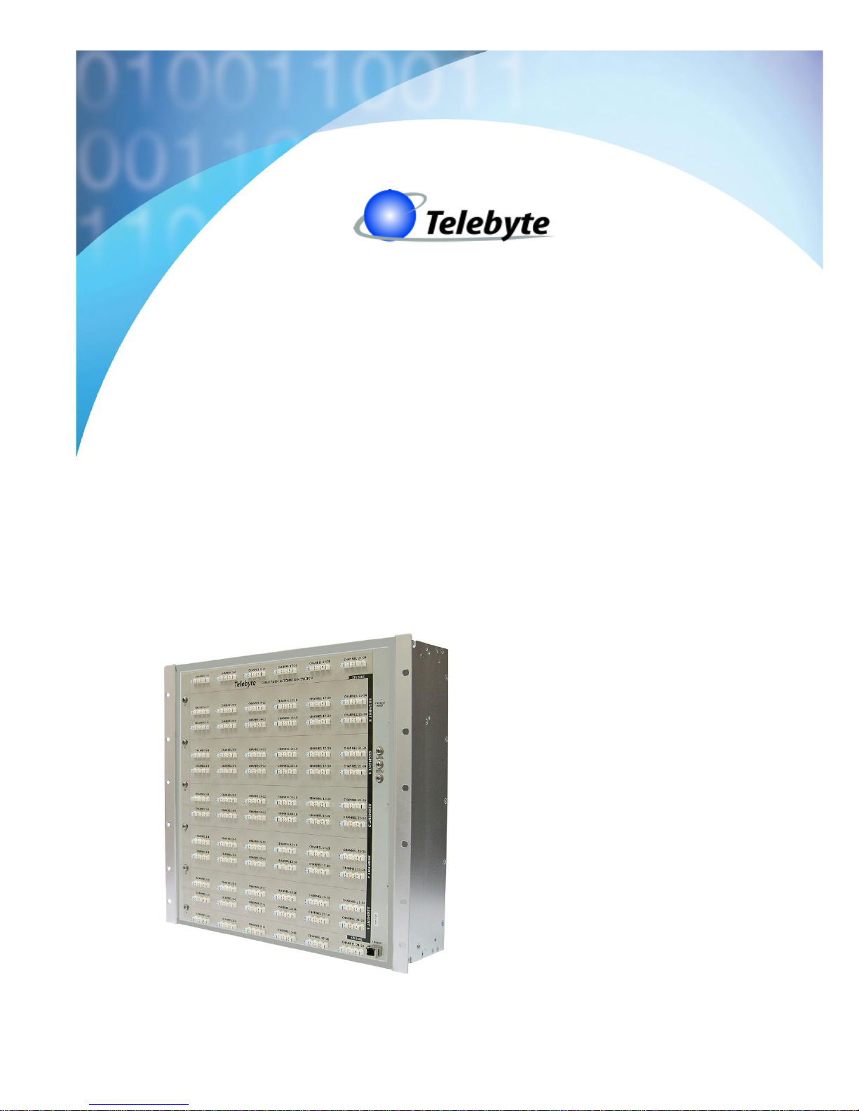
The Model CFA-24 Transparent Cable Farm Automation Switch is a transparent, electrically neutral, switching device
that allows up to twenty-four incoming cable farm lines (twisted pairs) to be switched to five different loop segments.
Operating in a frequency band up to 212 MHz, the CFA-24 is highly suited to lab-grade testing of next-gen devices
where live crosstalk is required (e.g., VDSL2 Vectoring or G.fast performance testing). Telebyte’s superior transparency
delivers excellent crosstalk accuracy. Ideal for ID-337 G.fast Certification and TR-249 VDSL2 Vectoring testing.
Configurations may be expanded by adding channel expander units, allowing users to scale the number of pairs that can
be switched from 24 to as many as needed, in groups of 24. In addition, segment extender units can be jumpered together
to add more line segments.
The CFA-24 Transparent Cable Farm Automation Switch.
Model CFA-24 Transparent Cable Farm Automation Switch Reference Manual Page 2 of 76
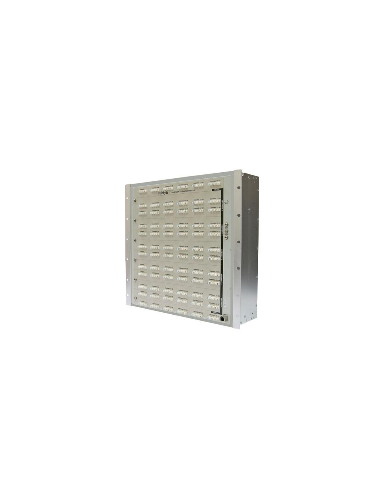
Configurations may be expanded by adding channel extender units, allowing users to scale the number of pairs that can
be switched from 24 to as many as needed, in groups of 24. In addition, segment extender units can be cabled together
to add more line segments.
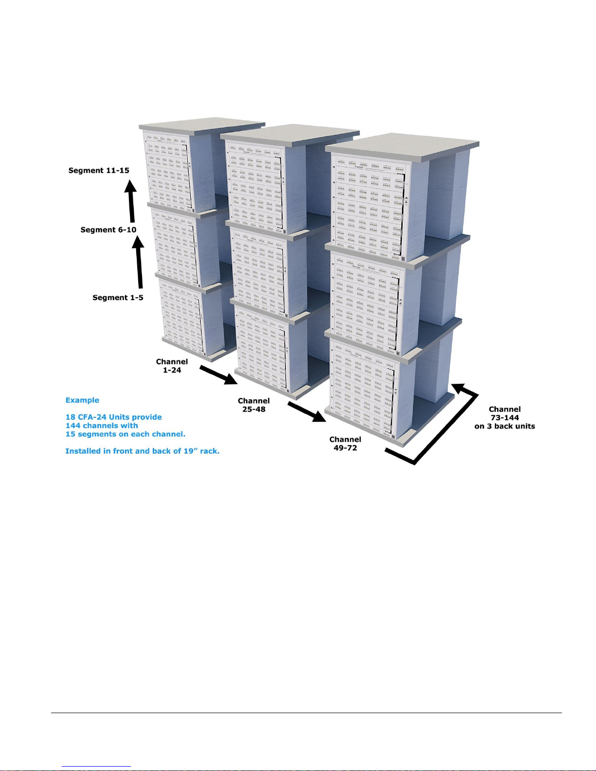
The example above shows 18, CFA-24 units installed in three racks. This would provide 15 segments and 144
channels. A configuration can be as simple as one unit (with 5 segments and 24 channels) or extended
and expanded up to 15 segments and as many channels as needed. Installation in the front and back of a
19” rack reduces the amount of racks required.

Model CFA-24 Transparent Cable Farm Automation Switch Reference Manual Page 3 of 76
1.2 Main Features
• Ideal for Broadband Forum’s ID-337 G.fast Certification and TR-249 VDSL2 Vectoring Testing
• High performance transparent solution designed to automate testing of cable farms
• Use additional units to expand the number of segments and channels
• Multiple Vectoring groups per unit or across multiple units
• Colocated and non-colocated test configurations
• Connect cables once then switch programmatically
• Automatically terminates unused channels and/or segments
• Micro-Interruptions
• Supports Reverse Powering for G.fast
• Low crosstalk/low insertion Loss
• Control/Power via Power Over Ethernet (POE)
• Embed remote commands in scripts (e.g., TCL, Python)

Model CFA-24 Transparent Cable Farm Automation Switch Reference Manual Page 4 of 76
1.3 Specifications
Specifications
Switching Capability
Switching of up to 5 loop segments for 24 local loops
(expandable by adding channel expanders and/or segment
extenders)
Insertion Loss across all 5 Segments
in Bypass (from CO side to CPE side)
• DC to 17 MHz: less than 0.3 dB
• 17 MHz to 30 MHz: less than 0.38 dB
• 30 MHz to 106 MHz: less than 0.57 dB
• 106 MHz to 212 MHz: less than 0.89 dB
Noise Floor
Less than -153 dBm/Hz
Channel-to-Channel Isolation
• DC to 17 MHz: minimum 81 dB
• 17 MHz to 30 MHz: minimum 76 dB
• 30 MHz to 106 MHz: minimum 68 dB
• 106 MHz to 212 MHz: minimum 63 dB
Impedance
100 ohms
Temperature
• Operating: 0°C to 50°C (32°F to 122°F)
• Storage: -20°C to 70 °C (-18°F to 158°F)
Operating Relative Humidity
0% to 95% relative humidity (non-condensing)
Connectors
• CO Input/Output: 6 x 8 Way Punch Down Blocks
• CPE Input/Output: 6 x 8 Way Punch Down Blocks
• Line Segments: 60 x 8 Way Punch Down Blocks
• Control: RJ45 (Power over Ethernet)
Conductors Accepted
• Diameters from 0.6 mm to 0.4 mm
• Solid conductors
• Shielded or unshielded
Dimensions
Overall: 17.50”H x 16”W x 6”D (10-U High)
Rack mountable (front and/or back) in 19” rack
Micro-Interruptions
Location: CO or CPE side - on any one channels
Interrupt Time: 5ms to 100ms in 1-ms increments
Power
POE per 802.3af standard
Cycles of Operation
1,000,000 Minimum
DC Rating Maximum Voltage Tip - Ring
220 VDC/250 VAC, 2 amperes maximum
Specifications are subject to change without notice. Made in USA.
Ordering Information
CFA-24
24-Channel Transparent Cable Farm Automation Switch (Controller, Channel or
Segment Extender)
RJ45x24-PP
24-channel female CAT6 RJ45 patch panel w/solid conductor, 6 feet; 1-U high, to
connect to CO and/or CPE side of test.
CFA-Custom Cable
Custom cable kit to connect to CO and/or CPE side of test.
CFA-CA-MGT
Cable Management Kit. Includes 6 rack-mountable cable-tie bars with cable ties.
CFA-POE-1
PHIHONG PSA16U-480(POE) 1-PoE Ethernet Adapter
CFA-POE-4
Linksys LGS108P 8-port switch with 4 PoE+ ports
CFA-POE-8
Linksys LGS116P 16-port switch with 8 PoE+ ports
CFA-POE-12
Linksys LGS124P 24-port switch with 12 PoE+ ports
CFA-PDTOOL
Punch down tool
CW1420-400
Spool of CW1420 400 m cable (4 pairs) for ID-337 testing
All switches verified and qualified for use with the CFA-24.
Contact Telebyte to request qualification of alternate switch for use with this product.

Model CFA-24 Transparent Cable Farm Automation Switch Reference Manual Page 5 of 76
2.0 About This Manual
This reference manual describes, and is organized by, the five basic processes required to set up and begin testing with
a CFA system. Each has its own level of complexity and requisite understanding of the cable farm, required test
configuration and simple running of tests. In addition, user management is available to restrict menu access to
appropriate personnel.
2.1 Chronological Order of Processes
➢ It is very important to follow this order of processes. In particular, establish the CFA network (Process 1) before
punching down any cables.
PROCESS
DESCRIPTION
1
Establish CFA Network
o The correct way to connect CFA-24 unit
o How to assign static IP address to each unit
o Powering the CFA network
2
Installation Configuration Management
o Overall set up of entire CFA system.
o Configure Multiple Vectoring Groups (Optional)
o Complexity is dependent upon the number of units in the system.
o Prepares the system for the Test Maintenance process
3
Test Maintenance
o Sets the line lengths available for selection during the Set Channel
Lengths/Interrupts process
o Set Colocated, Non-Colocated
4
Connect Cable Farm
o Connect cable farm to all CFA-24 punch down blocks
5
Set Channel Lengths/Interrupts
o Select channel lengths
o Configure and start micro-interruptions
A section on basic concepts precedes the Installation Configuration Management and Connect Cable Farm sections to
orient the reader involved in these processes. The basic concepts section is not required reading for the Test Maintenance
and Set Channel Lengths/Micro-Interruptions sections.

Model CFA-24 Transparent Cable Farm Automation Switch Reference Manual Page 6 of 76
3.0 Before You Begin
➢ Do not punch down cable to the CFA-24 until you have read this document and the reference manual. The last
step in setting up your system is punching down the cable.
➢ Always use the punch down tool approved by Telebyte.
3.1 Establish CFA Network
Do not connect CFA-24 units with the same IP address to the POE switch. The CFA-24 units do not
support DHCP. A default static IP address for each CFA-24 is configured at the factory and must be
changed if there is more than one unit in the CFA network. Connect only one unit at a time to the POE
switch while a new IP address is assigned through the web browser interface. This prevents IP address
conflicts which can prevent communication with the CFA-24.
3.2 Connecting Standalone CFA-24 to POE Adaptor
CFA-24 Default IP Settings:
IP:172.16.21.241
Subnet Mask: 255.255.255.0
When the CFA network consists of only one (Standalone) unit, the CFA-24 is most likely connected to power via
a POE adaptor (CFA-POE-1). The IP address for the Standalone unit may be changed from the factory default if
desired but this is not required. If the CFA network consists of two or more units, see Connecting CFA-24 to POE
Switch in the next section.
1. Plug the POE adaptor into a power source.
2. Configure the remote PC with an IP address in the same subnet of the CFA’s IP.
3. Connect a remote PC to the IN port of the POE adapter.
4. Connect the CFA to the OUT port of the POE adapter and wait at least 75 seconds for the CFA-24 to boot up.
An LED in the front of the unit turning from RED to GREEN indicates the system is ready.
5. From the remote PC, open a web browser and enter the factory default IP: 172.16.21.241 to communicate with
the CFA-24 unit.
6. The Main screen is displayed.
OUT IN
CFA
PC
!
IMPORTANT
Model CFA-24 Transparent Cable Farm Automation Switch Reference Manual Page 7 of 76
Telebyte recommends the use of these web browsers:
Google Chrome v. 54.0.2840.71
Firefox Mozilla v. 49.0.2
Next Steps:
a. If changing the factory default IP address to a new static IP, proceed to Changing Factory Default IP
Address later in this document.
b. If powering down the unit, proceed to Proper Shut Down Procedure later in this document.
c. If ready to continue to the next step in configuring the Standalone unit, proceed to Definitions.
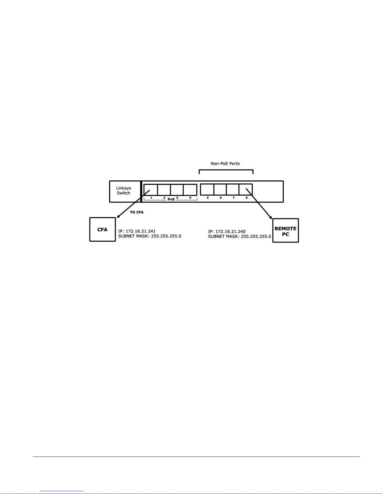
3.3 Connecting CFA-24 to POE Switch
Example shows the CFA-POE-4 (8-port version). User may have the 16 or 24-port version.
1. Plug the Linksys switch into a power source.
2. Configure the remote PC with an IP address in the same subnet of the CFA’s IP.
3. Connect a remote PC to the IN port of the POE adapter.
4. Connect the CFA-24 to the POE port. Note: When configuring the first unit, connect only that CFA-24
to a POE port as shown in the diagram above. After that, additional units may be plugged in providing
they have a different IP address from any other CFA connected.
5. Wait at least 75 seconds for the CFA-24 to boot up. An LED on the front of the unit turning from RED
to GREEN indicates the system is ready.
6. From the remote PC, open a web browser and enter the factory default IP: 172.16.21.241 to
communicate with the CFA-24 unit.
7. The Main screen is displayed.
8. unit.
9. The Main screen is displayed.
Next Steps:
a. Proceed to Changing Factory Default IP Address.

Model CFA-24 Transparent Cable Farm Automation Switch Reference Manual Page 8 of 76
3.4 Changing Factory Default IP Address
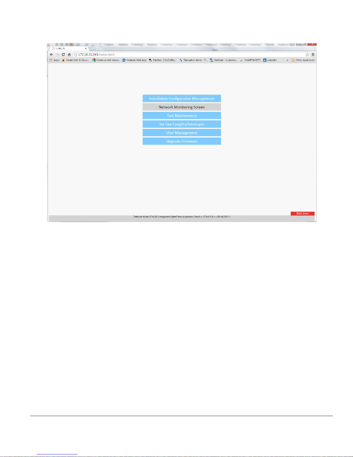
1. Select Installation Configuration Management from the Main screen.
Web Browser Main screen.
➢ Menu options that are grayed out are not available in the current Operational Mode. See Understanding
Operational Modes later in the document.
2. The Authentication Required dialogue box is shown. Depending on the browser, the look of this dialogue box
and the message displayed may vary.
3. Enter the following information in the Authentication Required dialogue box when prompted, and then click
OK (or Log In).
User Name: admin
Password: admin
The Installation Configuration Management screen is shown.

Model CFA-24 Transparent Cable Farm Automation Switch Reference Manual Page 9 of 76
Installation Configuration Management Screen
4. Change the default IP to the new static IP address of 172.16.21.231. Then click Submit.
➢ All subsequent units configured must be assigned a different IP address to avoid a conflict. After the set up
of the first unit, increment each IP address by 1 for each new CFA-24 unit being configured.
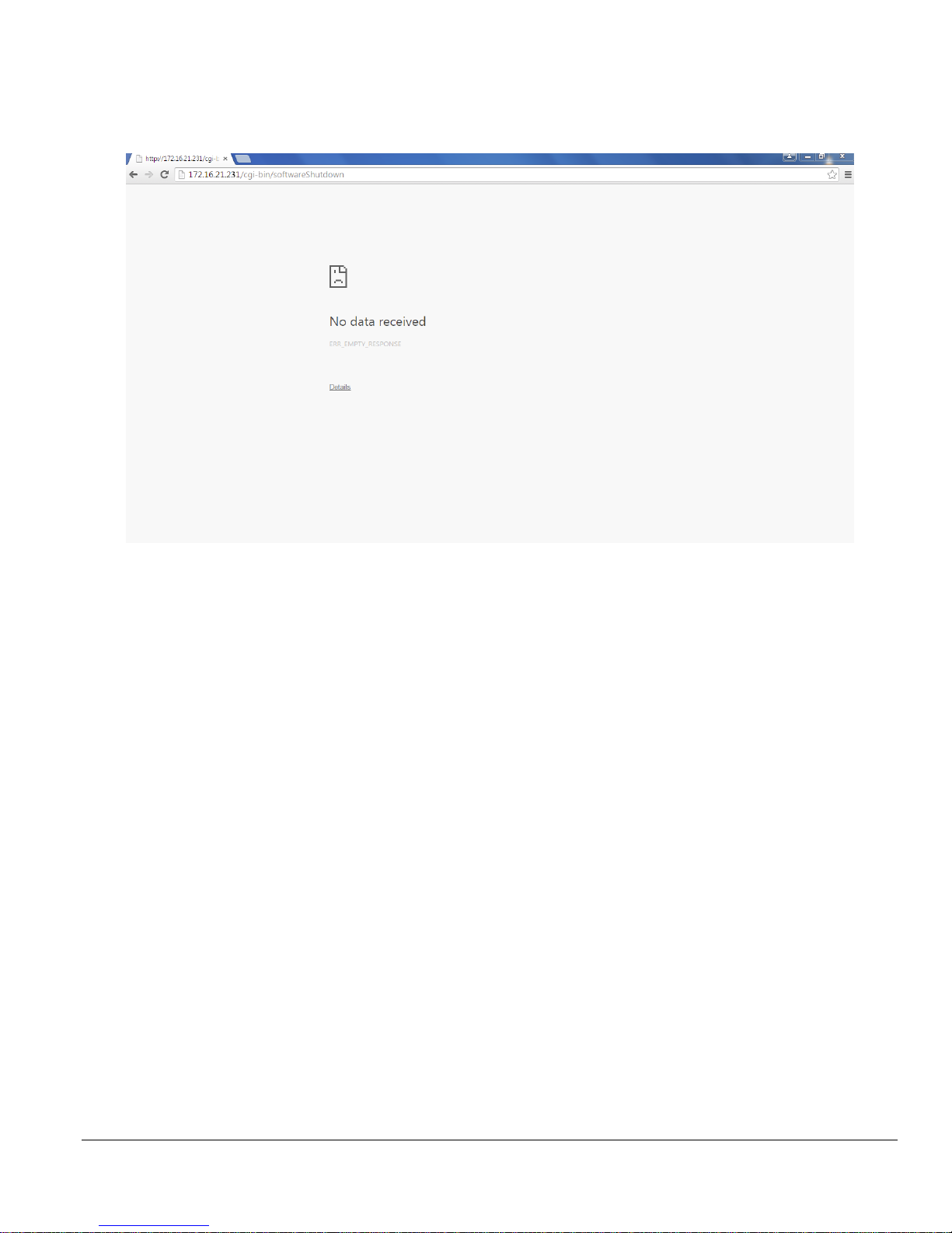
An error screen is displayed when the CFA-24 loses connectivity due to the IP address change. Depending on the
browser, this message may vary:
Next Steps:
a. Optional: To regain communication, enter the newly assigned IP address in the web browser. If any
issues arise, see Reset Switch later in this document.
b. Optional: While not required, the unit may be powered down at this time. If powering down the unit,
proceed to Proper Shut Down Procedure later in this document.
c. Optional: Return to Step 3 of Connecting CFA-24 to POE switch to configure more units.
d. If ready to continue with setting up the CFA network, proceed to Definitions.

Model CFA-24 Transparent Cable Farm Automation Switch Reference Manual Page 10 of 76
3.5 Proper Shut Down Procedure (for Systems purchased before 1/1/2016)
This procedure is always followed before the Ethernet cable is unplugged from the unit.
➢ For instructions on proper shut down using remote commands, see Appendix B – Remote Commands.
1. Enter the IP address of the unit (e.g., 172.16.21.231) in the web browser to connect. The Main screen is shown.
2. Click the Shut Down button in the lower-right corner of the Main screen.
Shut Down button in lower-right corner of Main screen.
3. When Prompted to shut down, click OK in the dialogue box.
Model CFA-24 Transparent Cable Farm Automation Switch Reference Manual Page 11 of 76
4. The CFA-24 connection is lost when the system shuts down.
The appearance of the message shown below may vary, depending on the browser.
➢ VERY IMPORTANT: Wait 30 seconds to allow the system to discharge completely before attempting to
reconnect the unit.
5. Unplug the CFA-24 Ethernet cable.
Model CFA-24 Transparent Cable Farm Automation Switch Reference Manual Page 12 of 76
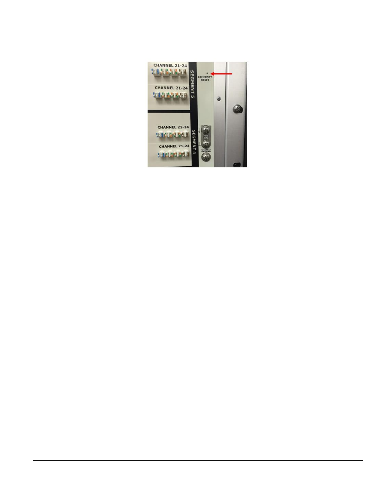
3.6 Reset Switch
Should it become necessary to reset the IP address to the factory default, use the Ethernet Reset button as described
below.
The Ethernet Reset button is located in the upper-right-front side of the unit.
1. With the CFA-24 powered ON, insert a paperclip into the Ethernet Reset hole and depress the switch for one
second to restore the CFA-24 factory default Network Configuration.
2. Wait at least 2 minutes before attempting to establish a new Ethernet connection.
3. Enter 172.16.21.241 in the web browser from a pre-configured remote computer with the same Subnet Mask.
Factory Default Settings:
IP: 172.16.21.241
Subnet Mask: 255.255.255.0
Default Gateway: 172.16.21.1
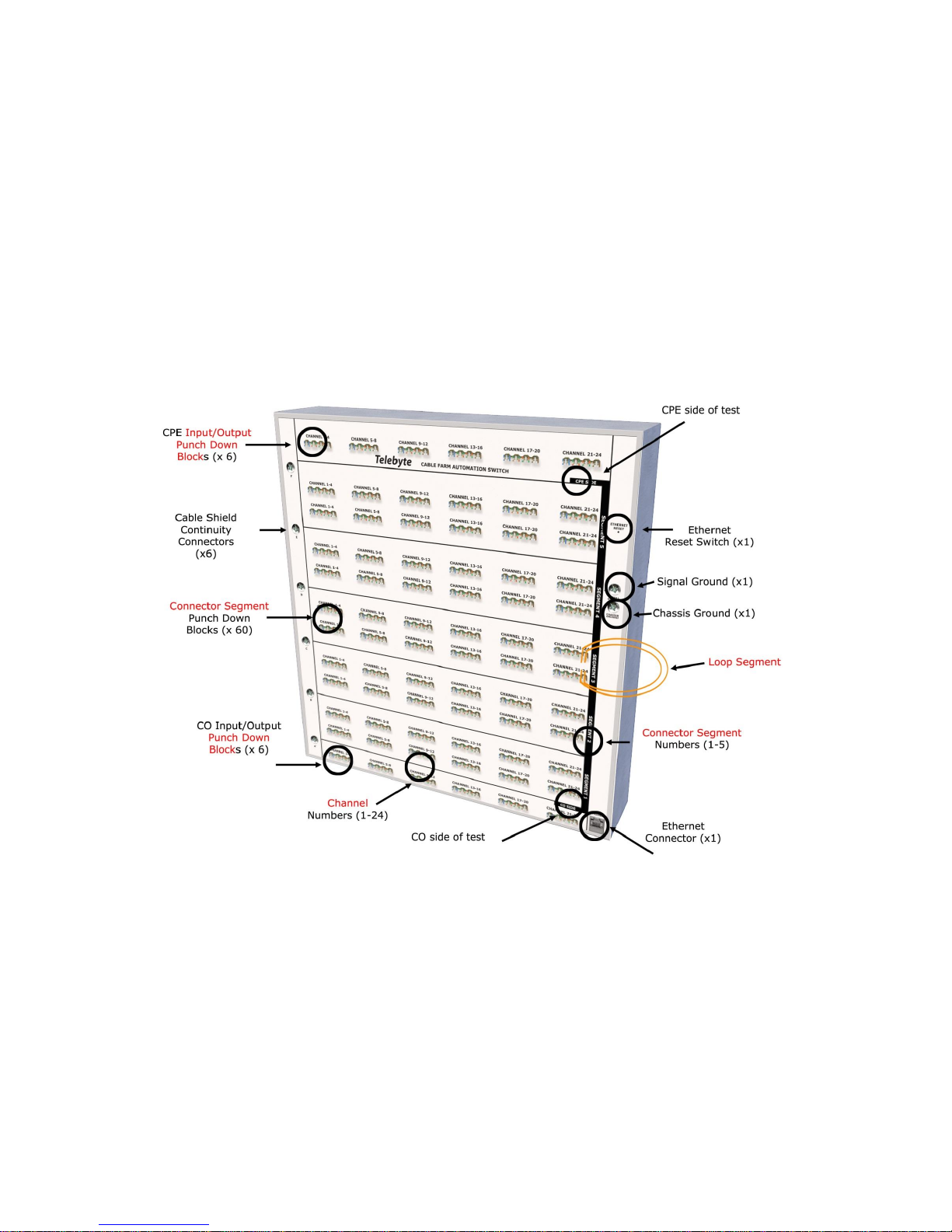
4.0 Definitions
Refer to the diagram above when reading this section.
Model CFA-24 Transparent Cable Farm Automation Switch Reference Manual Page 14 of 78
4.1 Loop Segment
A loop segment is a length of twisted-pair cable attached to the CFA-24. Loop segments may have different lengths. In
addition, loop segments may be connected and then, when required, bypassed programmatically.
➢ All crosstalk in a CFA system occurs between the cable farm wires. The CFA-24 is transparent.
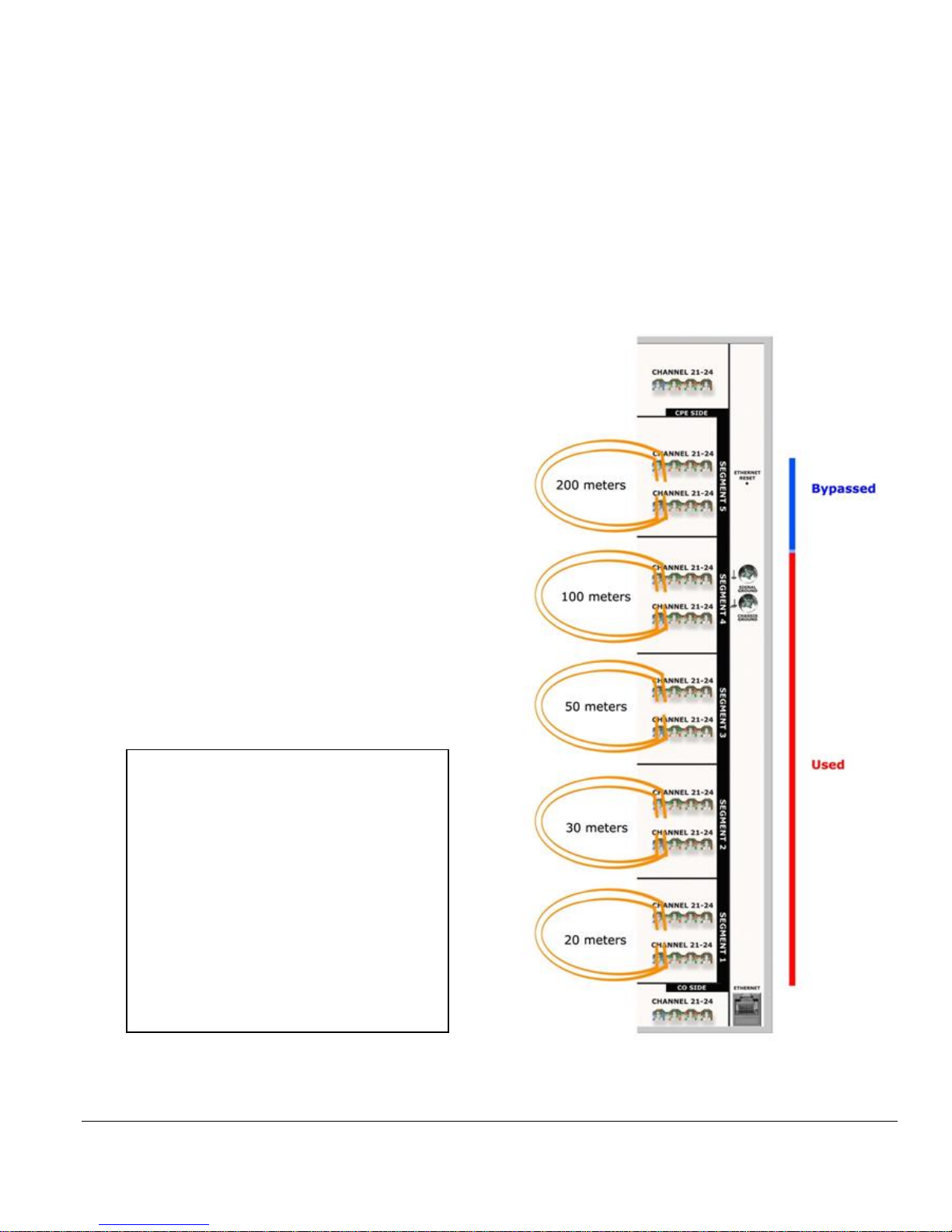
Example ID-337 Test Setup
(Selection of 200 meters)
• Five loop segments of different
lengths of CW1420 are each attached
to one of five segments.
• The allowable loop lengths of this
non-colocated setup are 20, 50, 100,
200 and 400 meters.
• Segments 1, 2, 3, and 4 are used to
form the 200 meters. Segment 5 is
bypassed.
Recommended Cable Lengths
for ID-337
For ID-337 Telebyte recommends
installation of the following cable
segment lengths, in the order
shown:
Segment 5 200m
Segment 4 100m
Segment 3 50m
Segment 2 30m
Segment 1 20m

Model CFA-24 Transparent Cable Farm Automation Switch Reference Manual Page 15 of 78
Example TR-249 Issue 1 Test Setup
(Selections of 150, 300, 450, 600 and 750 meters)
• Five 150-meter, 0.4mm loop
segments are each attached to
one of five segments.
• The allowable loop lengths of this
setup are 150, 300, 450, 600 and
750 meters.
• Segments 1, 2, 3 and 4 are used
to form the 600 meters. Segment
5 is bypassed. This configuration
represents the Medium Loop (17
MHz profile) per TR-249 Issue 1.
Recommended Cable Lengths
for TR-249
For TR-249 Telebyte recommends
installation of the following cable
segment lengths:
Segment 5 150m
Segment 4 150m
Segment 3 150m
Segment 2 150m
Segment 1 150m
Model CFA-24 Transparent Cable Farm Automation Switch Reference Manual Page 16 of 78
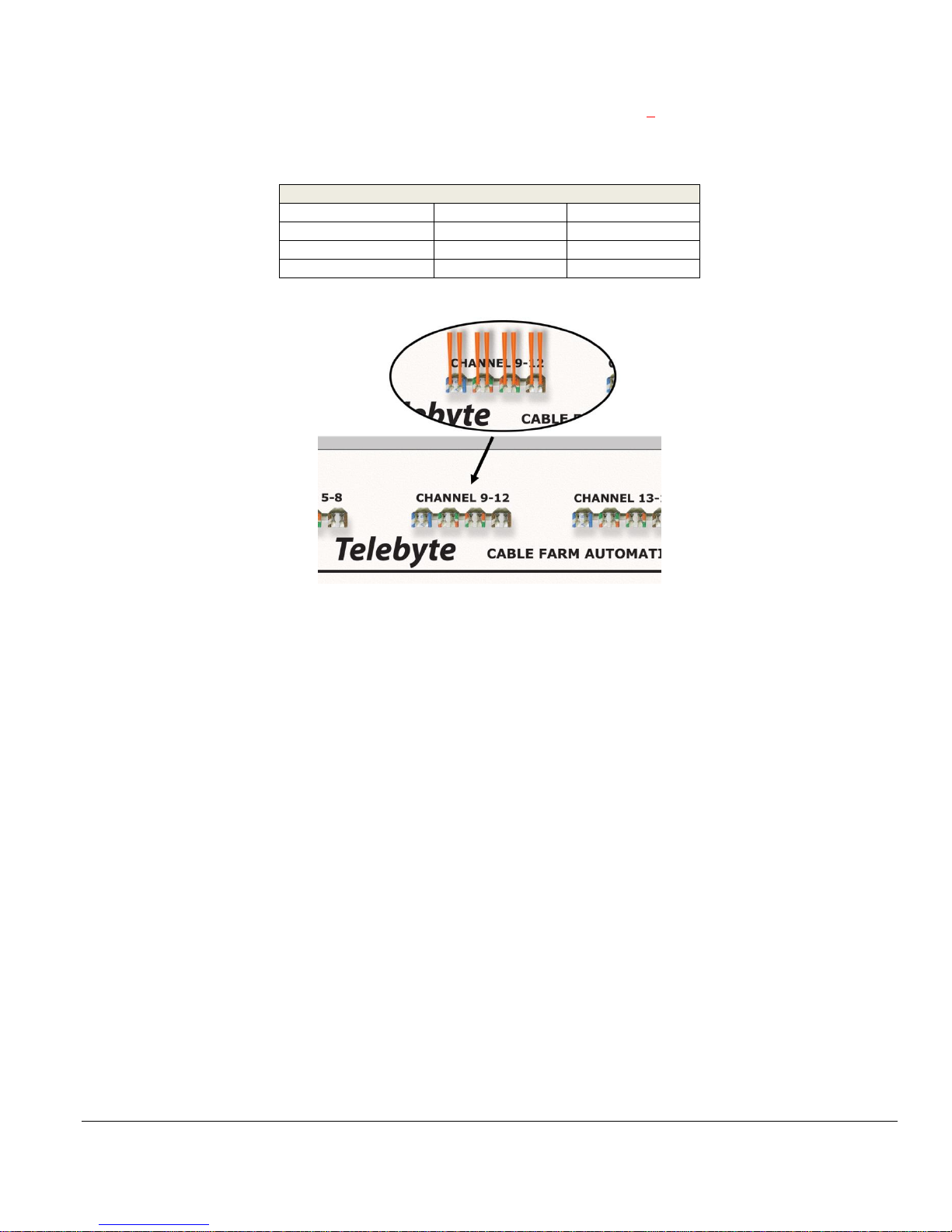
4.2 Punch Down Block
Each punch down block accepts 4 twisted-pair AWG22-26 solid wire connections. There are a total of 72 punch down
blocks on the front of the unit. 60 are dedicated to loop segment connections (two per loop segment) while 12 (referred
to as input/output connectors) are used to connect to the CO or CPE side of the unit (6 on top and 6 on bottom).
AWG-Metric Wire Equivalent Table
AWG Size (mm)
AWG Dia. (in)
Metric Dia.
26
0.0159
0.405
24
0.0201
0.511
22
0.0644
0.253
The punch down block for the CPE-side input/output connections of channels 9-12 is shown above.
4.3 Input/Output Connectors
Punch down blocks provide connectivity for the input/output connectors located on the top and bottom rows of the
CFA-24.
4.3.1 CPE Input/Output Connector
The top row connects to the CPE side. These connectors may also be used to jumper to another unit, where applicable.
4.3.2 CO Input/Output Connector
The bottom row connects to the CO side. These connectors are also used to cable to another unit, where applicable. See
Using CFA-PDTOOL-KIT for instructions.
• Use short cables for CPE and CO jumpers to CFA-24 Extenders that are the same as the Segment cable wire.
Maintain the twists of the pair across the jumper length between the CFA-24 Extenders.
Model CFA-24 Transparent Cable Farm Automation Switch Reference Manual Page 17 of 78
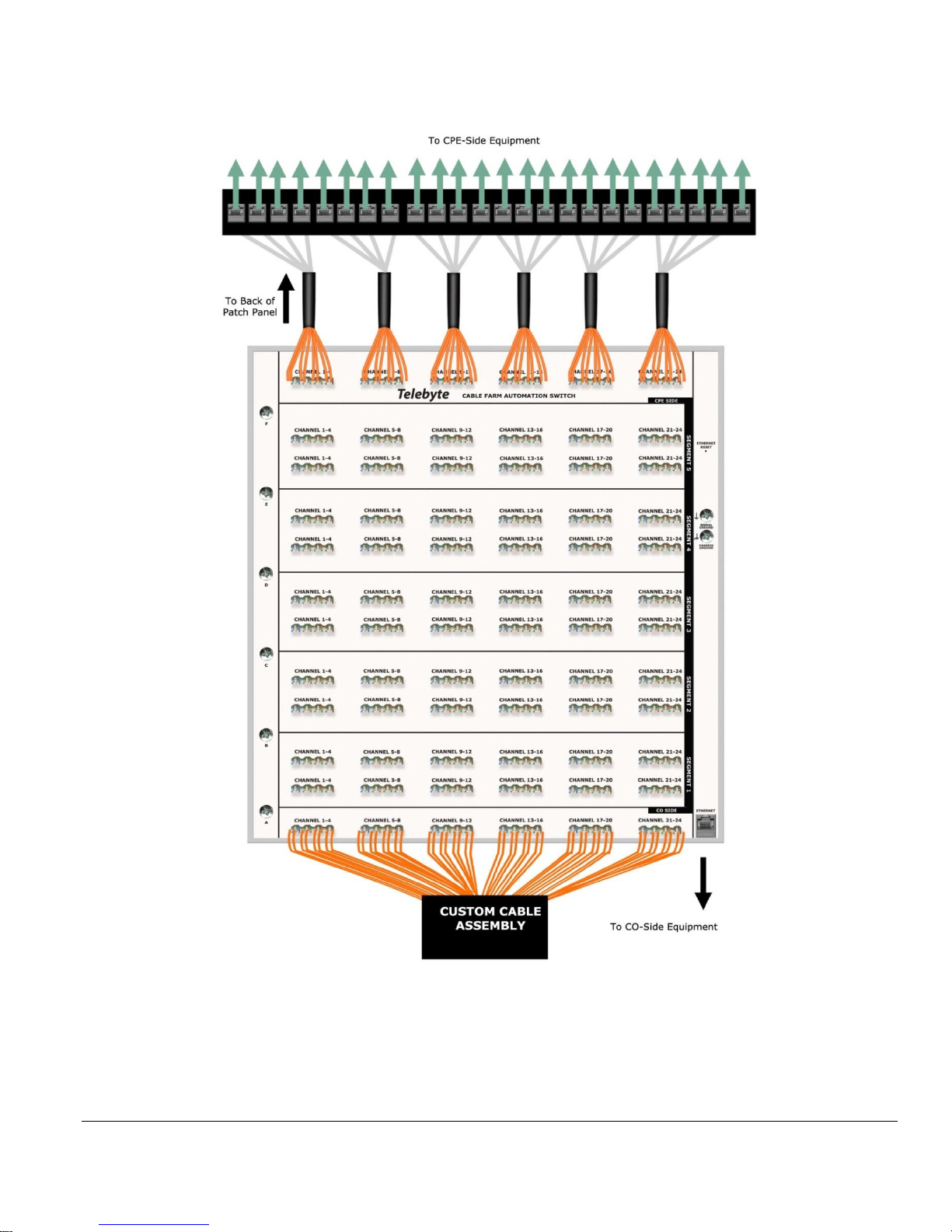
4.3.3 Custom Cable Set Example
The custom cable set usually consists of a patch panel and cables with custom lengths and terminations. This allows
the user to connect to the input/output punch down blocks once then use the patch panel to connect and disconnect
CO and CPE equipment. One custom cable set may be ordered for each side of the test. This illustration is conceptual
only and does not show other elements such as connections for shield ground continuity.

Model CFA-24 Transparent Cable Farm Automation Switch Reference Manual Page 18 of 78
4.3.4 Cabling Segment Extender Units
Multiple CFA-24 units can be used to extend the number of connector segments available. This requires a minimum of
two units to be cabled (jumpered) together such that the CO cable of one CFA-24 connects to the CPE of the other CFA-
24. The number assigned to a connector segment on more than one Extender unit will depend on the sequence in which
each unit is cabled.
Example of CO/CPE side cabling when using CFA-24’s as segment extenders. This illustration is conceptual only and
does not show other elements such as connections for shield ground continuity.

Model CFA-24 Transparent Cable Farm Automation Switch Reference Manual Page 19 of 78
4.4 Connector Segment
Connector segment numbers (1-5) are identified on the right side of the unit. Loop segments are connected to punch
down blocks (top and bottom) located within a given connector segment. Five vertical connector segments form a
channel.
4.5 Channel
A series of five vertical connector segments form a channel. Channels are numbered from 1 to 24, beginning on the left
side of the unit, unless there are multiple units. If so, the channel numbers will increment by 24 on each subsequent
CFA-24 used to extend the number of channels.
Channels can be grouped by Vectoring Groups (optional).
Channel 4 is highlighted above in red. It consists of 12 vertical punch down block connectors that make up five
connector segments and two input/output connectors.

Model CFA-24 Transparent Cable Farm Automation Switch Reference Manual Page 20 of 78
4.6 Coordinates
A coordinate is the physical location of two punch down block connections that form a specific connector segment
number and channel number combination. There are 120 coordinates in the Matrix of coordinates (5 connector segments
x 24 channels). This identification allows the channel/segment combination to be addressed during the configuration
process. A coordinate is further defined by length and type (see Matrix of Coordinates in the CFA-24 Configuration
section later in this manual).
4.7 Coordinate Matrix
The Coordinate Matrix is made up of the 120 coordinates (5 connector segments x 24 channels) physically located on
the front of a CFA-24 unit. These coordinates are defined by attributes such as coordinate type and coordinate length.
These definitions must match the cable farm lines physically attached to the unit. All Coordinate matrixes are combined
together by the CFA-24 software to form a Network Monitoring interface that allows the user to oversee the entire CFA
network.
4.8 Network Monitor
Once each CFA-24 unit is configured, multi-unit CFA systems may be viewed in their entirety via the Network Monitor
screen. The Network Monitor displays IP addresses and connection status for all units. The user may also add or remove
a unit from the CFA system or take a unit offline.

Model CFA-24 Transparent Cable Farm Automation Switch Reference Manual Page 21 of 78
5.0 Installation Configuration Management Process
The following steps are required before the Test Maintenance Process can be initiated.
➢ It is assumed that the first process, Establish CFA-24 Network, has already been followed. If not, stop and go
to that section before proceeding.
5.1 Understanding Operational Modes
The Installation Configuration Management process establishes which units are in the CFA-24 network and how they
will behave. During the Installation Configuration Management Process, each CFA-24 is assigned one of three
Operational Modes. In the case of the one-unit network, the CFA-24 is always set to Standalone mode. In the multi-unit
network, one unit is set as the Controller and the others are set as a type of Extender (for channels 25 and higher or
segment 6 and higher).
5.1.1 Standalone Mode (applies to one-unit network)
The CFA-24 is set to Standalone mode when it is the only unit in the setup. Throughout this manual, the term “CFA-24
Network” refers to single and multi-unit setups.
5.1.2 Controller Mode (applies to multi-unit network)
The CFA-24 is set to Controller mode when it is used for channels 1-24 and segments 1-5 in a multi-unit network.
5.1.3 Extender Mode (applies to multi-unit network)
Extenders operate in one of three ways:
• Channel Extender: The CFA-24 is set to the Channel Extender mode when the unit extends only the number of
channels available. When used, the unit’s location in the channel numbering sequence is also assigned.
• Segment Extender: The CFA-24 is set to the Segment Extender mode when the unit extends only the number
of segments available. When used, the unit’s location in the segment numbering sequence is also assigned.
• Segment AND Channel Extender: The CFA-24 is set to the Segment AND Extender mode when the unit
extends the number of segments AND the number of channels available. When used, the unit’s location in the
segment AND channel numbering sequence is also assigned.
Relationship of Controller to Extender Units
In multi-unit CFA-24 Networks, all Extenders are associated with one Controller unit by entering the Controller’s IP
address during Extender configuration. Once all Extenders are configured, the Controller is the only unit accessed.
Model CFA-24 Transparent Cable Farm Automation Switch Reference Manual Page 22 of 78
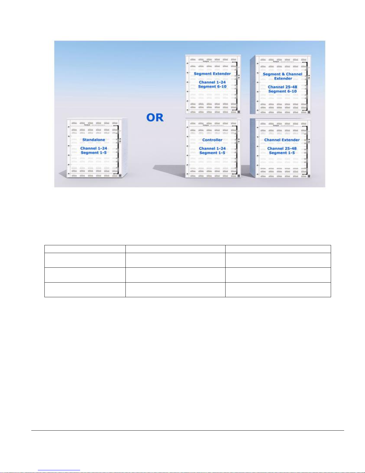
Example of CFA-24 Operational Modes
Assigning Channel and Segment Numbers
All channel range and segment ranges must be unique for each CFA-24. The following shows the allowable
combinations:
CH range 1-24
CH range 25-28 or higher
Segment range
1-5
Standalone or Controller
Channel Extender
Segment range
6-10
Segment Extender
Segment & Channel Extender
Segment range
11-15
Segment Extender
Segment & Channel Extender
The begin the Installation Configuration Management process, the user sets the static IP address and Operational Mode
of each unit. This is required to populate the Coordinate Matrix screen which is used to identify all coordinates in the
network and their features. All of these activities result in a Network Monitoring Map. The Network Monitoring Map
allows units to be added and removed from the system and displays the current status of all units in the system.
➢ The CFA-24 is designed specifically for VDSL2 Vectoring and G.fast technologies; therefore, only those
options consistent with that type of testing are presented to the user.
Model CFA-24 Transparent Cable Farm Automation Switch Reference Manual Page 23 of 78
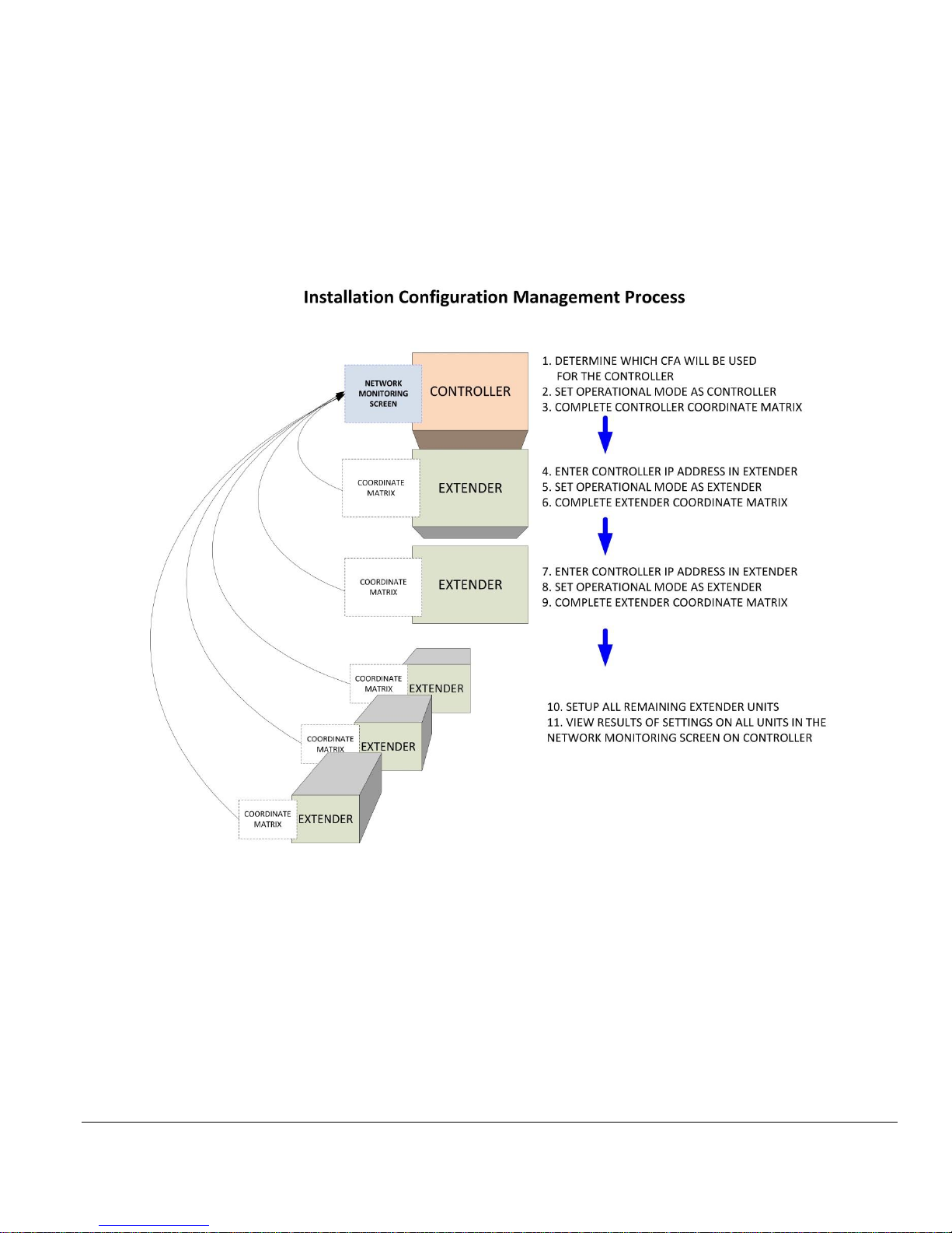
5.2 Steps in Installation Configuration Management Process
1. If configuring a multi-unit CFA network, determine which CFA-24 (and related IP address) will operate in
Controller mode.
2. Configure Coordinate Matrix of Controller (or Standalone) unit.
3. Add Controller’s IP address to Segment and/or Channel Extenders to link them to the Controller
4. Assign Operational Mode of remaining units including channel and/or segment range
5. Complete Coordinate Matrix of remaining units
6. Optionally, configure multiple Vectoring Groups (Multi-pairs) on Controller (or Standalone) unit
7. Display/edit Network Monitoring Map on Controller.

Model CFA-24 Transparent Cable Farm Automation Switch Reference Manual Page 24 of 78
5.3 Launching the CFA-24 Configuration Software
The CFA-24 is connected to a remote PC via an Ethernet POE switch or POE adaptor (connected to an Ethernet switch),
depending on the number of units in the CFA network.
• Enter the static IP address of the CFA-24 unit to access the CFA configuration software. The Main screen is
shown.
The Main Screen.
5.4 Configure Individual Units
5.4.1 Overview
Entering the IP address of a CFA-24 unit via a remote PC connected to the CFA-24 network launches the CFA-24
software.
➢ IP addresses are established during the first process, Establish CFA Network. If you have not done so, stop and
go to that section before proceeding.
Model CFA-24 Transparent Cable Farm Automation Switch Reference Manual Page 25 of 78
5.4.2 Instructions for Linking Extender Units to the Controller
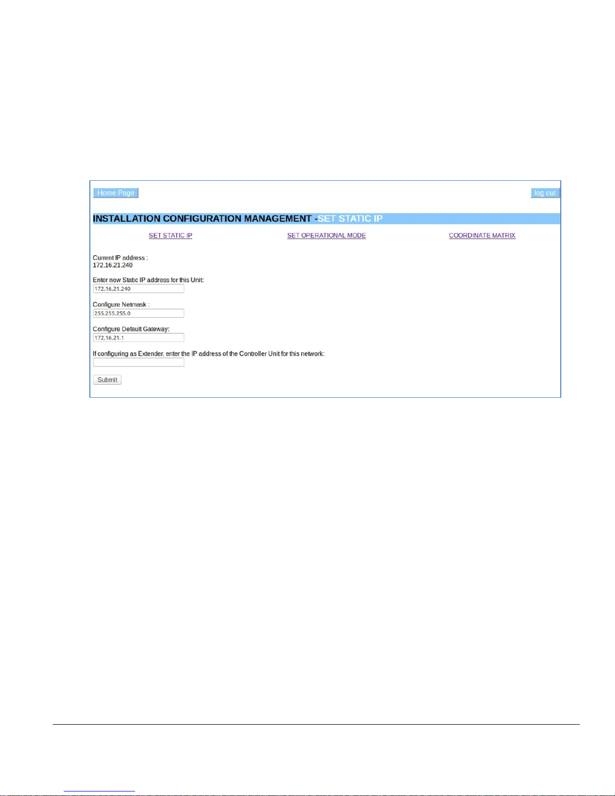
Set/Change Static IP
It is assumed the Establish CFA Network process has been completed and, if applicable, the IP address of the Controller
unit selected. The instructions that follow are used to enter the Controller IP address in the SET STATIC IP screen
when linking Extenders to the Controller. If the CFA system has only one unit, this section does not apply.
• Select Installation Configuration Management from the Main screen. The INSTALLATION
CONFIGURATION MANAGEMENT - SET STATIC IP screen is shown.
Set Static IP screen. The bottom field is used to enter the IP address of the Controller unit
to link an Extender unit to the Controller unit.
• If this unit is an Extender unit, enter the Controller IP address in the If configuring as Extender . . . field to
link this Extender to the Controller unit.
• Click Submit to update all fields. A confirmation screen is shown.

Model CFA-24 Transparent Cable Farm Automation Switch Reference Manual Page 26 of 78
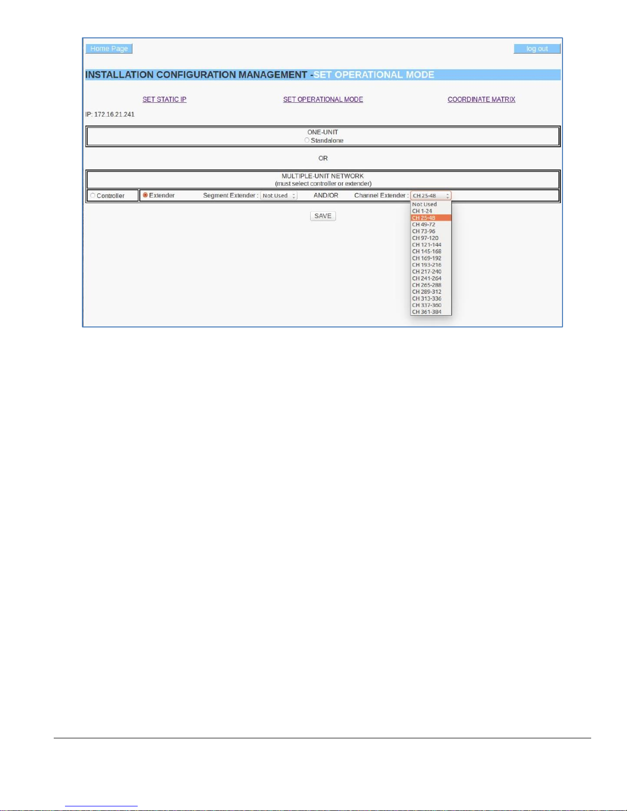
Set/Change Operational Mode
If not already connected, enter the IP address of a CFA-24 unit via a remote PC connected to the CFA-24 network to
launch the CFA-24 software.
• Select SET OPERATIONAL MODE from the INSTALLATION CONFIGURATION MANAGEMENT
screen.
The Set Operational Mode screen showing the selections for a Controller unit.
The Set Operational Mode screen showing the selections for a Segment Extender unit used for segments 6-10.
Model CFA-24 Transparent Cable Farm Automation Switch Reference Manual Page 27 of 78
The Set Operational Mode screen showing the selection for a Channel Extender unit used for channels 25-48.
• Single-Unit Networks
o Click the Standalone radio button.
o Click Save to update the target unit. A confirmation screen is shown.
• Multi-unit network
o Controller Unit
▪ Click the Controller radio button (the channel range is must also be 1-24 and the segment
range 1-5 for the Controller);
OR
o Extender Unit
▪ Click the Extender radio button
▪ For Segment Extenders, select the segment range for this unit (this range appears in the
Coordinate Matrix; AND/OR
▪ For Channel Extenders, select the channel range for this unit (this range appears in the
Coordinate Matrix).
o Click Save to update the target unit. A confirmation screen is shown.
Model CFA-24 Transparent Cable Farm Automation Switch Reference Manual Page 28 of 78
Configure Coordinate Matrix
The Coordinate Matrix defines the coordinate types and length for each segment:channel combination on the target
CFA-24. The selections for the coordinate type must match the physical cable attached to the CFA-24 segment:channel.
The information from each Coordinate Matrix combines with all others to form the overall characteristics of the CFA24 system.
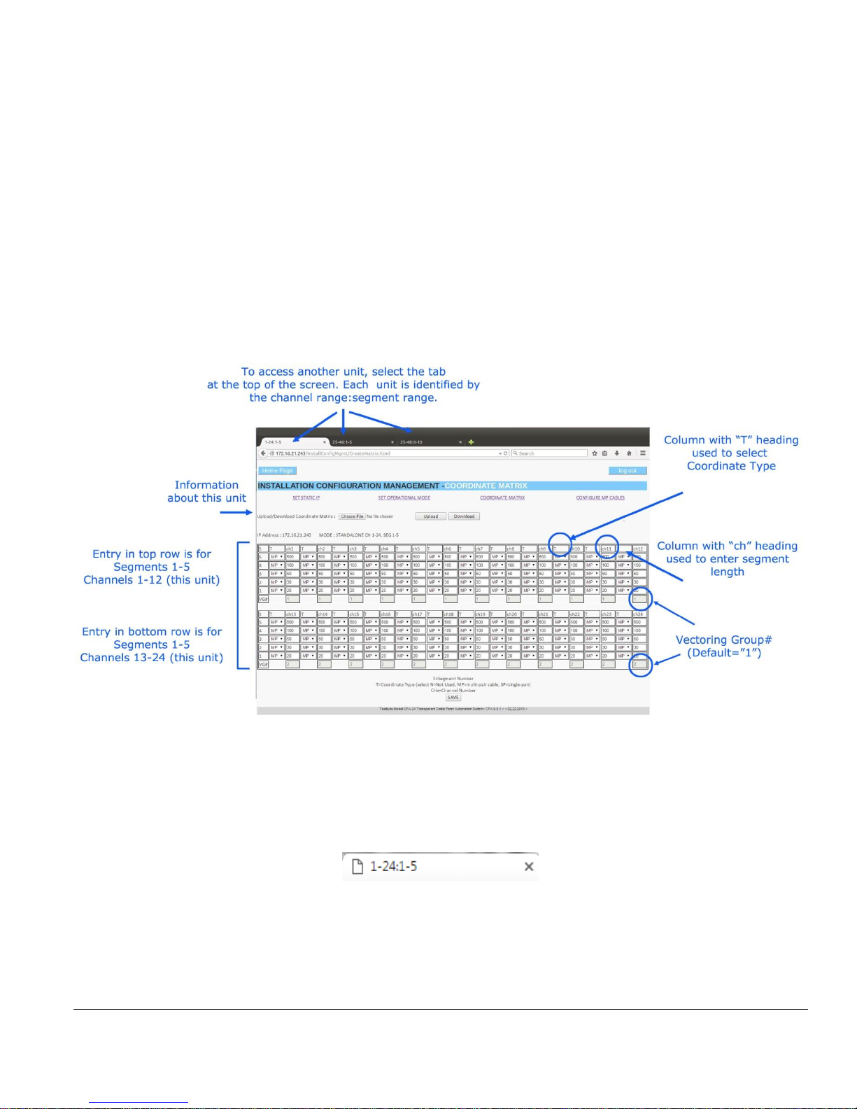
Elements of the Coordinate Matrix screen
The Coordinate Matrix screen is divided into two rows, the topmost is for channels 1-12 and the bottommost for
channels 13-24. Both rows display the connector segment number on the left side. Columns with a “T” heading are used
to select the Connector Type. Columns with a “CHx” heading are used to enter a loop length for the channel. Vectoring
Group numbers (VG#) are shown at the bottom of each channel.
Connector Types are selected and loop lengths are entered directly. Vectoring Group numbers are configured through
the Configure MP Cable function. The resulting Vectoring Group number assignments are displayed on the Coordinate
Matrix screen. The Configure MP Cable function is only available on a Controller or Standalone unit as Vectoring
Groups are system-wide.
The Coordinate Matrix screen always shows a segment range of 1-5 and a channel range of 1-24 (on a unit basis). To
view the current unit’s channel:segment range in the complete CFA-24 system, view the tabs at the top of the screen to
see the actual channel:segment range (on a system-wide basis). For example, the tab below shows the current Coordinate
Matrix is for channels 1-24 and segments 1-5.

Model CFA-24 Transparent Cable Farm Automation Switch Reference Manual Page 29 of 78
Multiple Vectoring Groups (Configure MP Cables)
A Vectoring Group (VG) is used to identify a specific selection of channels for the purpose of setting independent
available line lengths for that selection. The available line lengths can be varied by including or excluding segments
independently from one VG to another. It is assumed all channels in a given Vectoring Group are connected to cables
between which there is crosstalk. In addition, a Vectoring Group may be designed as Colocated or Non-Colocated.
For example, the user may wish to attach two binders, each with four cables, to a CFA and have independent control of
the line lengths available for selection for each binder. In this example, the user would configure two Vectoring Groups
of four channels each.
Vectoring Groups apply to the entire CFA system; therefore, they are configured on the Controller or Standalone unit
only.
When using Multi-Pairs in the Coordinate Matrix, the CONFIGURE MP CABLES option must be used to configure
the Vectoring Groups.
List of Rules for defining a Vectoring Group:
• A minimum of 2 channels is required for any VG.
• All channels in the VG must contain at least one MP coordinate.
• The channels within a VG are not required to be sequential.
• The channels within a VG are not required to belong to the same CFA-24 unit.
The number of available Multiple Vectoring Groups is calculated by adding together all channels in the entire CFA
system that contain at least one MP coordinate. This number is then divided by two (a minimum of two channels are
required per VG) and, if necessary, rounded down to the next lowest whole number.
Once the number of VG’s is selected, each channel is assigned to a specific VG by the user. After each VG is established,
the user may include or exclude segments (if Non-Colocated) for any VG independently, allowing for different line
length settings per VG.
➢ The default number of Vectoring Groups is 1.

Model CFA-24 Transparent Cable Farm Automation Switch Reference Manual Page 30 of 78
Considerations When Selecting Coordinate Types and Lengths
The CFA-24 solution is designed for VDSL2 Vectoring and G.fast testing. Selections are verified to be certain they do
not deviate from the appropriate choices for this type of testing. In the event this occurs, the row containing the error is
highlighted.
Multi-pair vs Single-Pair Selections
There is a difference in the Allowable Line Lengths results in Test Maintenance when assigning coordinate types of
Multi-Pairs vs Single Pairs in the Coordinate Matrix screen:
• Multi-Pairs:
o Allowable Line Lengths results in Test Maintenance, for a particular channel, are determined by
adding each segment length, beginning with the CO side of the unit (on segment 1).
o The Test Maintenance screen is used to select which segments are included in the Allowable Line
Lengths computation.
o This coordinate type is required when enabling Multiple Vectoring Groups. All channels in a
Vectoring Group must contain at least one MP coordinate.
• Single-Pairs:
o Single-Pair segments are automatically included as part of the Allowable Line Lengths computation.
Rules
Multi-Pair Coordinate Type (referred to as MP’s below):
• When using MP’s on a particular channel, a minimum of two MP’s must be assigned to that channel.
• An MP must have the same length as all the other MP’s in the same segment row. This applies regardless
of how many Vectoring Groups are used.
• When configuring a series of MP’s on a particular channel, configure the first one (lowest numbered one)
beginning on the CO side. Any MP after that, on the same channel, must be assigned to a higher segment
number.
• If enabling multiple Vectoring Groups, the number of MP coordinates determines how many Vectoring
Groups are available for selection.
Single-Pair Coordinate Type (referred to as SP’s below):
• An SP can have any length.
• Multiple SP’s allowed per channel.
• Any SP segment number must be higher than any MP segment number on the same channel.

Model CFA-24 Transparent Cable Farm Automation Switch Reference Manual Page 31 of 78
Not Used (N) Coordinate Type:
• Any or all coordinates in a segment row may be designated as an N, even if that row has SP’s or MP’s.
• If a row has an MP and at least one N, then all channels that have an N in that particular row may only
have an N or SP above that point (i.e., in a higher segment number).
Example of Differences in Results
Using multi-pair coordinates only on all channels and segments:
CH1-24, Segment 1: 25
CH1-24, Segment 2: 50
CH1-24, Segment 3: 100
CH1-24, Segment 4: 200
CH1-24, Segment 5: 100
Potential available line lengths: 25, 75, 175, 375, 475
Using single-pair coordinates only on all channels and segments:
CH1-24, Segment 1: 25
CH1-24, Segment 2: 50
CH1-24, Segment 3: 100
CH1-24, Segment 4: 200
CH1-24, Segment 5: 100
Potential available line lengths: 25, 75, 100, 125, 150, 175, 200, 225, 250, 275, 300, 325, 350, 375,400, 425, 450, 475

Model CFA-24 Transparent Cable Farm Automation Switch Reference Manual Page 32 of 78
• Select COORDINATE MATRIX from the INSTALLATION CONFIGURATION MANAGEMENT screen.
The Installation Configuration Management screen example for a standalone unit.
• Select Coordinate Type from the dropdown field, under the “T” column for the desired coordinate. See
Considerations When Selecting Coordinate Types and Lengths.
o N: Represents “Not Used.” Select N when no loop segment is attached to this coordinate.
o MP: Select MP (multi-pair) when the loop segment attached to this coordinate is part of the multi-pair
cable portion of the test setup. It is expected that crosstalk occurs between multi-pairs. When using
Multi-Pairs in the Coordinate Matrix, use CONFIGURE MP CABLES to set up the number of
Vectoring Groups.
o SP: Select SP (single pair) when the loop segment attached to this coordinate is used for the single-
pair portion of the test setup.
• Enter Coordinate Length. This field is mandatory when the Coordinate Type is MP or SP. The value entered
must match the length of physical twisted multi-pair cable connected to a connector segment.
• VG#: Display field showing the current Vectoring Group number assigned to the channel. A blank field
indicates there is one Vectoring Group (default). If this unit is a Controller or Standalone and MP’s are
configured, select CONFIGURE MP CABLES to configure Vectoring Groups.

Model CFA-24 Transparent Cable Farm Automation Switch Reference Manual Page 33 of 78
• Click SAVE to update the target CFA-24. The confirmation screen is displayed, showing the selections
made.
➢ Entries for Multi-Pair lengths are not validated by the Save function when there is only one
Vectoring Group. This validation is performed on the Test Maintenance screen.
• Select CONFIGURE MP CABLES from the COORDINATE MATRIX screen
The Configure Multiple Pair (MP) Cables screen is shown above. In this example 4 Vectoring Groups are selected.
• Number of Vectoring Groups: The values in this dropdown field are determined by the number of MP
coordinates assigned, in all the Coordinate Matrix screens, for all CFA’s in the CFA system. Select the
number of Vectoring Groups desired. Once selected, the number of Vectoring Groups is displayed in the
upper-left corner of the grid. Note that selecting 1 Vectoring Group simply returns the user to the Coordinate
Matrix screen.
• VG #: assign a Vectoring Group (VG) number to each channel.
• PREVIEW: click to see a preview of all assignments.

Model CFA-24 Transparent Cable Farm Automation Switch Reference Manual Page 34 of 78
In the example of the PREVIEW screen above, 24 channels are assigned to four Vectoring Groups.
• SAVE: Click to update the CFA system or Cancel to return to Test Maintenance without saving. Once the
CFA system is updated, all Coordinate Matrix screens in the CFA system display the new Vectoring Group
number assignments under each channel.
Model CFA-24 Transparent Cable Farm Automation Switch Reference Manual Page 35 of 78
6.0 Display/Edit Network Monitoring Map
Once all Coordinate Matrixes are completed, the Network Monitoring Map may be viewed by accessing the Controller
unit.
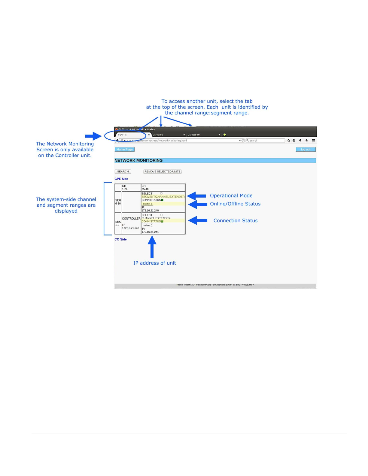
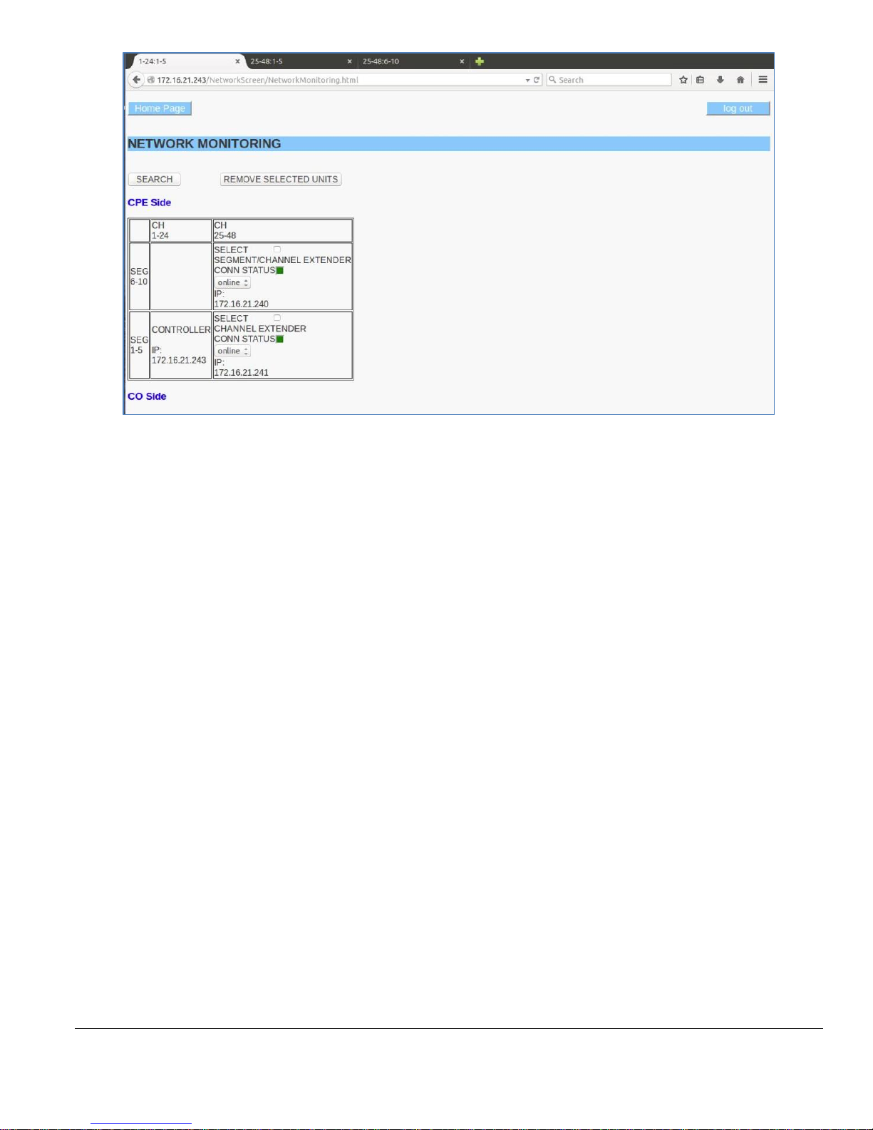
Elements of the Network Monitoring Screen
All information shown in the Network Monitoring screen is obtained from settings established during the previous
processes. In the example above, a system with a Controller, Channel Extender, and Segment/Channel Extender is
shown. Each unit is identified by its static IP address. Note the segment:channel ranges set during the Set Operational
Mode process are now all shown on a system-side basis.
The user may now manually place a unit off (or on) line, check the connection status, remove a unit from the system or
search to find units added to the system that are not yet shown.
Model CFA-24 Transparent Cable Farm Automation Switch Reference Manual Page 36 of 78
• Enter the IP address of the Controller unit. Select Network Monitoring Screen. The Network Monitoring screen
is displayed.
The Main Screen.
Model CFA-24 Transparent Cable Farm Automation Switch Reference Manual Page 37 of 78
The Network Monitor screen example shows a three-unit system.
Search: search the CFA-24 Network to discover all units where the Controller IP address value for that unit matches
the Controller’s IP address displayed on the Network Monitoring screen.
Remove Selected Units: any unit on the screen with the Select box checked is removed from CFA-24 Network when
this button is clicked. When the Search button is clicked, if the unit is still physically connected to the network and has
the same IP address as the Controller, it appears again in the Network Monitoring screen.
Select: checkbox used to select a unit for removal when the Remove Selected Units button is clicked.
Online/Offline: dropdown allows user to change the status of the related unit to online or offline. Online means the
unit should be included in the CFA-24 Network. Offline means that it should not be included in the CFA-24 Network.
This selection does not physically disconnect the unit.
• Manually taking a unit offline may cause other units to be taken offline also. For instance, taking the
unit using segments 1-5 (and channels 25-48) offline would force all units in a higher segment range
to be taken offline.
Conn (Connection) Status: A red LED appears when a unit is not communicating with the Controller. A green LED
appears when the unit is communicating with the Controller.
• A unit can have a connection status of “not connected” and still have an online status. This can occur
if the unit becomes physically disconnected but the user still wishes it to be in the CFA Network.
IP: shows the unique static IP address of the CFA unit.

Model CFA-24 Transparent Cable Farm Automation Switch Reference Manual Page 38 of 78
7.0 Test Maintenance Process
The Test Maintenance Process sets the line lengths that are allowed to be selected by the user during the Set Channel
Lengths/Micro-Interruptions process. The purpose is to control the available settings at the user level. All values shown
in the Test Maintenance screen are calculated based upon the configuration steps performed during the Installation
Configuration Management process.
7.1 Colocated and Non-Colocated Vectoring Groups
One or more Vectoring Groups may be designated as Colocated or Non-Colocated. The default is one Non-Colocated
Vectoring Group. The Colocated check box is used to make the designation.
Colocated:
• All segments selected automatically.
• Only MP’s are valid.
• SP’s are ignored.
• More line lengths available for selection.
Non-Colocated:
• Control over which segments are included.
• Both MP’s and SP’s are valid.
Understanding Colocated and Non-Colocated
This relates to the lengths of the twisted pair cables between the CO (DPU or DSLAM) and CPE’s in a vectoring
group. When the cable lengths in the vectoring group are equal, then the vectoring group will be colocated. When they
are unequal, then the vectoring group will be non-colocated.
Examples:
Colocated – The connection from the CO terminates at an MDU (multiple dwelling unit). All the cables in the binder
(vectoring group) are the same length.
Non-Colocated – Each CPE connected to the CO is located at a different distance from the CO. Cables terminate at
the various CPEs and leave the binder (vectoring group), resulting in unequal line lengths within the binder.
The behavior of FEXT (Far End Crosstalk) in a colocated vectoring group is different from that found in a noncolocated vectoring group. This is due, in part, to the fact that crosstalk is affected by the proximity of cables to each
other. When the lengths are different, the proximity varies. A colocated vectoring group might be used for testing
when the greatest FEXT is needed.
Model CFA-24 Transparent Cable Farm Automation Switch Reference Manual Page 39 of 78
7.2 Instructions
7.2.1 Accessing Test Maintenance
• Enter the IP address of the Controller unit to access the Main screen. Click TEST MAINTENANCE.
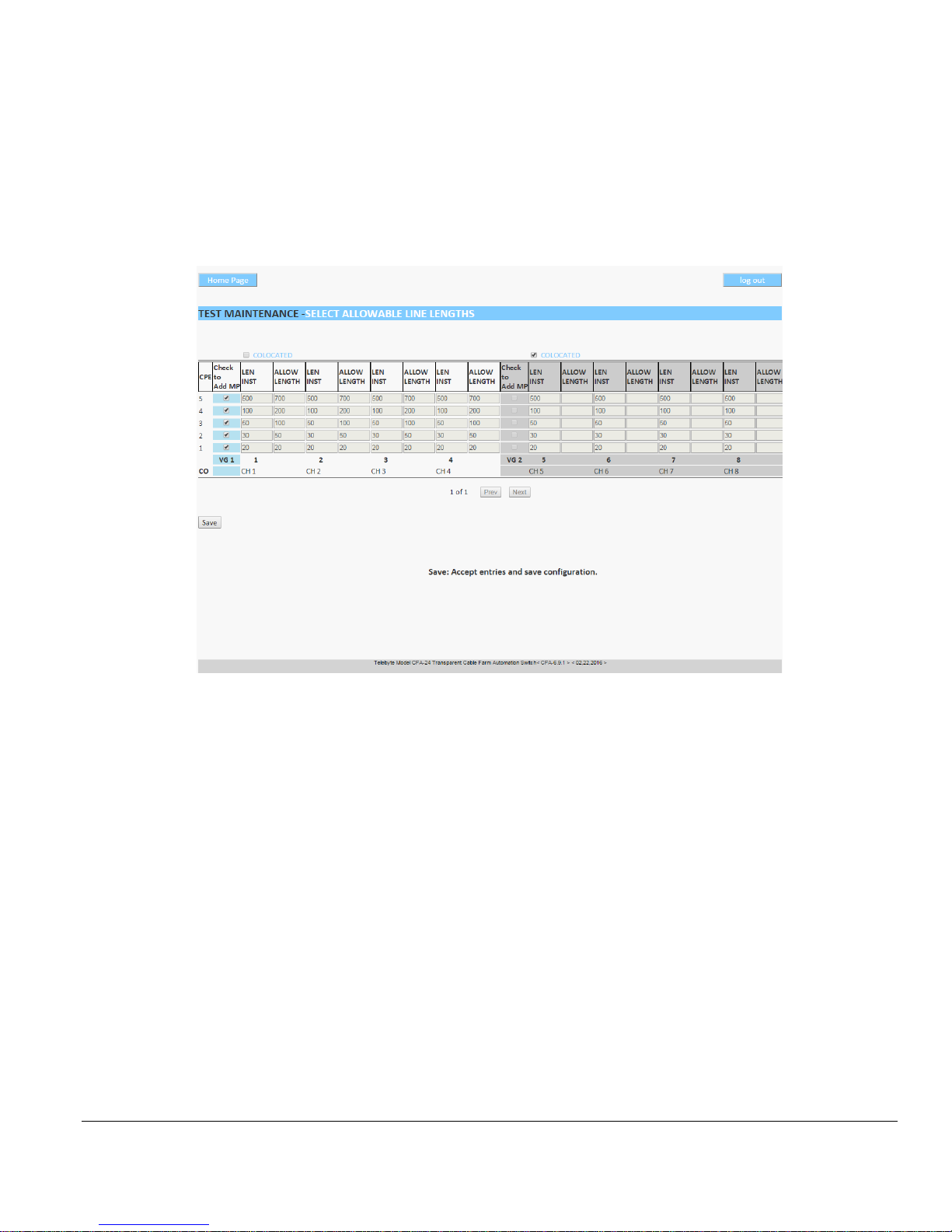
The SELECT ALLOWABLE LINE LENGTHS screen is shown.
The SELECT ALLOWABLE LINE LENGTHS screen allows the user to configure the line lengths available for
selection by checking off which segments to include.
For Colocated Vectoring Group
Colocated: check this box to designate the Vectoring Group as Colocated. If checked, the entire Vectoring Group is
grayed out.
For Non-Colocated Vectoring Group:
Check to Add MP: check this box to include the segment number (shown to the left of check box) and all related
lengths in that row for the range of channels on the screen. Each segment selected becomes a loop increment available
for selection. Note: Anytime the Coordinate Matrix is updated, confirm the Check to Add MP boxes of the Test
Maintenance page are correct and press Save before setting any line length in the “SET LENGTH” screen.
LEN INST: displays the length of the loop segment established during the Installation Configuration Management
process.
ALLOW LENGTH: displays the resulting length available to the user during the Set Lengths and Interrupts Process.
Note the values in this field are derived from the LEN INST values in the checked segments.
• Click SAVE to save this configuration and update the Test Maintenance screen.

Model CFA-24 Transparent Cable Farm Automation Switch Reference Manual Page 40 of 78
Use the Prev and Next buttons to navigate from one VG to another. This may be necessary when there are a large
number of VG’s.
➢ Anytime the Coordinate Matrix is updated, confirm the Check to Add MP boxes of the Test Maintenance screen
are correct and press Save before setting any line length in the “SET LENGTH” screen.
For the example screen on the previous page, the resulting available line lengths are:
VG1 (Channels 1-4): 0, 20, 50, 100, 200, 700
VG2 (Channels 5-8): 0, 20, 30, 50, 70, 80, 100, 120, 130, 150, 170, 180, 200, 500, 520, 530, 550, 570, 580, 600, 620,
630, 650, 670, 680, 700

Model CFA-24 Transparent Cable Farm Automation Switch Reference Manual Page 41 of 78
8.0 Making Connections Process
8.1 Steps in Making Connections Process
1. Rack mounting (optional)
2. Segment twisted-pair loop segments connected to coordinate punch down blocks.
3. Connection of CO and CPE-side equipment
4. Establishing Cable Shield Continuity
5. Establishing proper grounding
6. Connecting Segment Extenders
8.2 Rack Mounting (optional)
To allow for dense installations, each unit may be installed in the front and/or back of a standard 19” rack. In addition,
three rack mount options make installation customizable.
➢ Care should be taken to leave space for easy access to the back of the unit. This
area contains an access door that may need to be used at some point.

Model CFA-24 Transparent Cable Farm Automation Switch Reference Manual Page 42 of 78
8.2.1 Placement of Rack-Mounting Brackets
There are two rack-mounting brackets on the CFA-24, one on each side. Each bracket is movable and may be
used to control the position of the unit in the rack.
• The standard position is for the CFA-24 to be flush with the rack.
• For the Protruding position, remove the mounting bracket screws holding the side rack-mounting
brackets, move the brackets toward the rear and re-install the mounting bracket screws into the new
position. The CFA-24 then protrudes 2” out from the rack.
• For the Recessed position remove the mounting bracket screws holding the side rack-mounting
brackets, move the brackets toward the front and re-install the mounting bracket screws into the new
position. The CFA-24 then recesses 2” into the rack.
➢ Care should be taken to leave space for easy access to the back of the unit. This
area contains an access door that may need to be used at some point.
8.2.2 Mounting on a 19” Rack
The rack-mounting brackets on each side of the unit contain six holes for mounting onto a 19” rack. The
bottom of the CFA-24 should align with the half of the 0.5” space pattern (of the rack holes) that is followed
by the two 0.625” hole pattern (as shown below). Use the four (4) cage nuts at the top and bottom rackmounting bracket holes in the rack (that have been determined for CFA-24 attachment) and insert a screw
(provided) through the CFA-24 top and bottom rack-mounting bracket holes into the cage nut and tighten the
CFA-24 to the rack. Note: typically, #10, #12 and M6 mounting hardware is used.

Model CFA-24 Transparent Cable Farm Automation Switch Reference Manual Page 43 of 78
8.2.3 Using the CFA-24 without Rack Mounting
When using the CFA-24 without the rack mounting option, the rack-mounting brackets may be retained on the CFA-24
or removed.
WARNING
For personnel safety when not mounted on a rack, the metal enclosure of the CFA-24 must be earth
grounded. Connect an AWG18 wire to the ring lug at the rear of the CFA-24 (shown below) and
connect the other side of the wire to a good earth ground.
Model CFA-24 Transparent Cable Farm Automation Switch Reference Manual Page 44 of 78
8.3 Segment Twisted-Pair Connection to Coordinate Punch Down Blocks
8.3.1 Segment to Punch Down Block Connection
Ø
Ø
Ø
Ø
Ø
Ø
Ø
Ø
Ø
Ø
Ø
CPE or Extender
SEG 5 in Punch Blocks
SEG 5 out Punch Blocks
CPE Punch Blocks
F
SEG 4 out Punch Blocks
E
Shield
Connector
Shield
Screw
SEG 4 in Punch Blocks
SEG 3 out Punch Blocks
Seg 3 in Punch Blocks
D
Ø
C
Seg 2 out Punch Blocks
Seg 2 in Punch Blocks
SEG 1 in Punch Blocks
SEG 1 out Punch Blocks
B
CO Punch Blocks
A
CO or Extender Cable
Shield
Screw
Shield
Screw
Shield
Screw
Shield
Screw
Cable Shield
CO or EXT IN
SEG 1 IN Tie
Bar
Seg 1
Seg 2
Seg 3
SEG 1 OUT
SEG 2 IN
Tie Bar
SEG 2 OUT
SEG 3 IN
Tie Bar
SEG 3 OUT
SEG 4 IN
Tie Bar
Seg 4
SEG 4 OUT
SEG 5 IN
Tie Bar
Seg 5
SEG 5 OUT
CPE or EXT
Tie Bar
Cable Shield
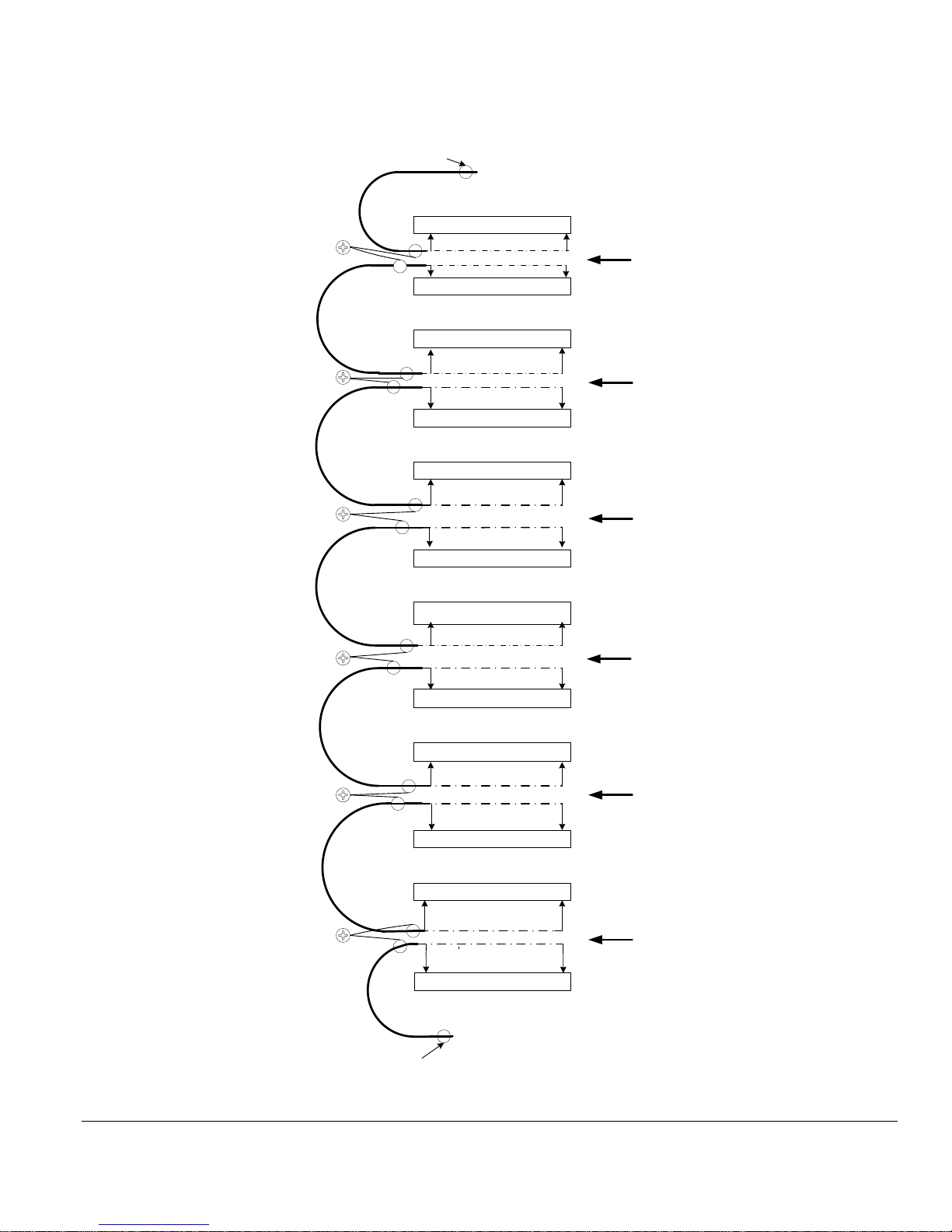
Segment Punch Down Block Connection Diagram

Model CFA-24 Transparent Cable Farm Automation Switch Reference Manual Page 45 of 78
Segment Wire Connection to the Punch Down Blocks
The channel connections for the 24 wire pairs of each Cable Segment is arranged in a horizontal row with Channel 1
wire pair at the far left side and Channel 24 wire pair on the far right side of each row. Each punch down block contains
eight (8) connections for 4-channel wire pairs where the Tip wire (T) is connected to the left side of the pair and the
Ring wire (R) is connected to the right side of the pair, as defined in punch down block figure that follows. Each wire
pair must retain its twists up to their separation at the punch down block. The wire enters the block from the lower side
of the block.
• Maintain tip-ring twists to the punch block.
• Do not strip the insulation off the wire. The
punch block will make connection through the
insulation.
• See CFA-PDTOOL-KIT for instructions.
Starting on left side of the Punch Down Block
Blue
Blue
T pair 1
Blue
R pair 1
Green
Orange
T pair 2
Green
Orange
R pair 2
Orange
Green
T pair 3
Orange
Green
R pair 3
Brown
Brown
T pair 4
Brown
R pair 4
Model CFA-24 Transparent Cable Farm Automation Switch Reference Manual Page 46 of 78
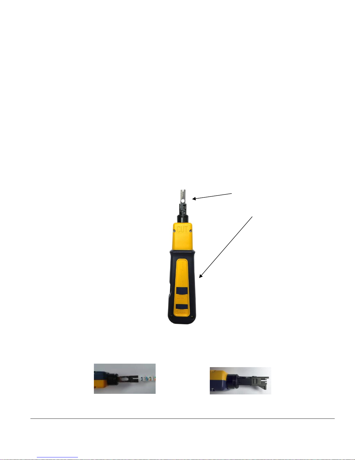
8.3.2 Using the CFA-PDTOOL-KIT to Punch Down Wire
Overview
The punch down blocks accept 22 AWG to 26 AWG solid wire. Due to the non-symmetrical nature of the punch down
blocks, the krone blade must be properly oriented to prevent damage to the connectors. The CFA-PDTOOL-KIT
contains the following tools for proper installation of the wires.
• Fluke Impact Tool
• Fluke Krone Blade
• Jonard Krone Blade
• Wire Cutter
Before You Begin
• When a connection is removed, the replacement wire must be the same AWG size or larger than the wire
removed. The punch down block is specified for 20 removals/replacements.
• Maintain tip-ring twists to the punch block.
• Do not strip the insulation off the wire. The punch down block itself will make connection through the
insulation.
The CFA-PDTOOL-KIT consists of a Fluke Impact Tool, Krone Impact Tool Blade, alternate Jonard Krone Blade and
a wire cutter. The Fluke Impact Tool is shipped with the Krone Impact Tool Blade already attached and the Jonard
Krone Blade stored inside the handle of Krone Impact Tool. To remove the Jonard Krone Blade, turn Release Blade.
To change from High Impact to Low Impact, turn LO HI IMPACT.
Correct orientation of the Jonard Krone Blade. Side view of the Krone Impact Tool Blade. Correct orientation.
Krone Impact Tool –
Blade and Handle

Model CFA-24 Transparent Cable Farm Automation Switch Reference Manual Page 47 of 78
Jonard Krone Blade with protective cap to cover blade end. The blade must be oriented as shown above or it may cause
damage the punch down block. If resistance is felt, check the orientation as it should slide into the block easily. The
opposite end is used to push the wire into the punch down block and the separate wire cutter is used to cut the wire.
Keep the red cap on the blade end to protect fingers, especially when inserting into the Krone Impact Tool for storage.
Instructions for Top Row of Punch Down Blocks (punched from above connector)
Tools:
1. Fluke Impact Tool
2. Jonard Krone Blade
3. Wire cutter
➢ Important! Orient the Jonard Krone Blade as shown below to avoid damaging the punch down block.
The Jonard Krone Blade showing the wire being pushed into the punch down block.
Use the wire cutters to cut excess wires from below the punch down connector.
Instructions for All Other Punch Down Blocks (punched from below connector)
Tools:
1. Fluke Impact Tool
2. Krone Impact Tool Blade
Press the wire into the punch down block. This will also automatically cut the wire. For 24 AWG or 26 solid wire use
the Low Impact setting. For 22 AWG solid wire use the High Impact setting

Model CFA-24 Transparent Cable Farm Automation Switch Reference Manual Page 48 of 78
Segment End Input and Output Side Pairing
To prevent punch down connection signal coupling, segment signals of equal level are retained near each other. For
Cable Management, a set of six (6) Segment Tie Bars are available, which mount to the 19” rack through the CFA Rack-
Mounting brackets, at positions that provide for pairing the cables as shown in the Segment Punch Down Block
Connection Diagram (referred to here as the Connection Figure). Each Segment Cable end is identified as an input or
output as shown in the Connection Figure. The input end is where a signal enters into a segment and the output end is
where the segment’s attenuated signal leaves the segment. As the output of a segment is at the same signal level as the
input to the next segment, these ends are placed on the same Segment Tie Bar (referred to here as a Tie Bar), which
prevents coupling from a stronger to a weaker signal end. Do not place other segment ends on the same Tie Bar as the
stronger signal end will couple into the weaker signal end.
As shown on the Connection Figure, the output of the CO cable and the input to SEG 1 cable are on the SEG 1 Tie Bar.
The CO wires are connected to the lower punch down blocks and the input to SEG 1 cable are connected to the second
punch down blocks. Similarly:
The output of SEG 1 and input to Seg 2 are on the same Tie Bar.
The output of SEG 2 and input to Seg 3 are on the same Tie Bar
The output of SEG 3 and input to Seg 4 are on the same Tie Bar
The output of SEG 4 and input to Seg 5 are on the same Tie Bar
The output of SEG 5 and input to the CPE Cable are on the same Tie Bar.
➢ To further minimize coupling it is recommended that the above cable segment pairs be alternated between the
left and right side of the CFA-24 rack to further increase the distance between weaker and stronger signals.
Example:
CO (or Extender) input and SEG 1 input on left side of rack
SEG 1 output and SEG 2 input on right side of rack.
SEG 2 output and SEG 3 input on left side of rack.
SEG 3 output and SEG 4 input on right side of rack.
SEG 4 output and SEG 5 input on left side of rack.
SEG 5 output and CPE (or Extender) output on right side of rack.

Model CFA-24 Transparent Cable Farm Automation Switch Reference Manual Page 49 of 78
8.3.3 Cable Shield Continuity
➢ Refer to the Segment Punch Down Block Connection Diagram ( see section 4.3 earlier in this text).
The CFA-24 includes Shield Continuity Connectors marked A-F located at the left side of the punch down blocks. The
A through F connection screws are isolated from each other and from signal and earth grounds. They provide a means
to “bond” the shield of a segment output end to the next segment input end. This provides for a continuous shield
connection from the CO to the CPE.
The CO cable shield is connected to Shield Continuity Connector “A” screw using a #10 ring lug. The SEG 1 input end
cable shield is also connected to the “A” screw which allows the SEG 1 cable shield to be connected to the CO shield.
In a similar manner, each output cable end and input cable end shield is connected to the same Shield Continuity
Connector as shown below. The Shield Continuity Connector screws are 10-32 size and the shield lugs are placed
between the stainless steel washer and screw-head to prevent damage to the pc board.
When less than five (5) segments are used the Shield Continuity Connectors must have jumpers connected to the Shield
Continuity Connector screws in order to maintain shield continuity to the CPE, as shown below.
Shield 1
Shield 2
Nylon Washer
S/Steel Washer

Model CFA-24 Transparent Cable Farm Automation Switch Reference Manual Page 50 of 78
SEG
1
SEG
2
SEG
3
SEG
4
SEG
5
CO or
Extender
CPE or
Extender
A B
C D E F
SEG
1
SEG
2
SEG
3
SEG
4
SEG
5
CO or
Extender
A B
C D E F
5 Segment Cable Shield Connections
3 Segment Cable Shield Connections and
2 Unconnected Segment Jumpers
CPE or
Extender
4.3.3 Cable Farm layout of Cable Recommendations
The spacing between cables is most important to limit coupling and crosstalk. Leaving the cable on a spool is convenient
but may result in higher coupling than occurs in the field and therefore not representative testing.
• Prevent folding a cable back and forth along its length where each length is nearby the previous length.
• Prevent placing different cables close to each other.
• For the higher frequencies of G.fast increasing separation of the cables is crucial.
• An alternate to increased spacing is to place each cable in an enclosed metal conduit tray to isolate them from
each other.

Model CFA-24 Transparent Cable Farm Automation Switch Reference Manual Page 51 of 78
8.4 CFA-24 Signal and Chassis Ground
The CFA-24 contains a Shorting Bar at the right side of the system near the Segment 4 marking. The Shorting Bar is
connected to the upper two of the three screws that connect the CFA-24 Signal Ground to Chassis Ground.
Should it be desirable to disconnect these grounds, loosen the three (3) screws two turns and rotate the metal Shorting
Bar around so that it contacts the center and lower screws and retighten the three (3) screws. The upper screw is Signal
Ground, the center screw is Chassis Ground, and the lower screw has no connection. The default position of the Shorting
Bar connects Signal Ground and Chassis Ground together.
➢ The center Chassis Ground screw is captive and can only be loosened 2-3 turns. Do not force
additional loosening turns.
WARNING
The CFA-24 power is isolated and is connected to chassis ground through the Shorting Bar. When the
Shorting Bar is moved from its default setting to disconnect Signal Ground from Chassis Ground, the
CFA-24 power will not be chassis ground referenced. Although the CFA-24 power is not available at
the user interface, opening the chassis with power present may provide an electrical shock to personnel.
8.5 Using Patch Panel (optional)
Available in future version of this manual
8.6 Cable CFA-24 Units Together to Extend Segments (optional)
When connecting two or more CFA-24 units together to extend the number of segments in the CFA system, Telebyte
recommends the following:
• Use a short cable that is the same wire type as the Segment for jumpering between CFA-24 Extenders.
• Keep the length of the jumper wires as short as possible.
• Maintain the wire pair twists between the punch down block connections.
9.0 Set Line Lengths and Interrupts Process
9.1.1 Steps in the Set Line Lengths and Interrupts Process
1. Select line lengths for each channel or terminate the line.
2. Configure micro-interruption settings.

Model CFA-24 Transparent Cable Farm Automation Switch Reference Manual Page 52 of 78
9.1.2 Instructions
Set Lengths
The values shown are configured during the Set Allowable Line Lengths step. Note: if the Coordinate Matrix has been
updated, go to the Test Maintenance page and confirm the Check To Include boxes are checked as desired and the page
is saved before attempting to set a line length.
• Select SET LENGTHS from the Test Maintenance screen. The SET LENGTHS screen is displayed.
Copy from . . .thru: copy value associated with selected channel to a range of channels.
Copy: click this button to copy the value configured in the Copy from . . . thru fields.
Channel: all channels in the network are displayed.
(Channel) Length: dropdown shows all allowable line lengths for the associated channel. Select either a line length
or TERM to terminate the channel.
SAVE: click SAVE to update all units to have the selected line lengths.

Model CFA-24 Transparent Cable Farm Automation Switch Reference Manual Page 53 of 78
Set Mechanical Interruptions
There are two types of mechanical interruptions that may be selected: Microcut or Cut. The interruptions may be set for
any one channel in the CFA-24 Network and placed on the CO or CPE, or CO & CPE (Standalone units only). An
interruption sequence consisting of the interrupt time and interval between interruptions (when repeated) can be set to
continue until a specific amount of time has elapsed. Interrupts are on tip and ring, simultaneously.
• After setting and saving at least one line length, Select INTERRUPT CHANNEL from the SET LENGTHS
screen.
Example Set Microcut screen.
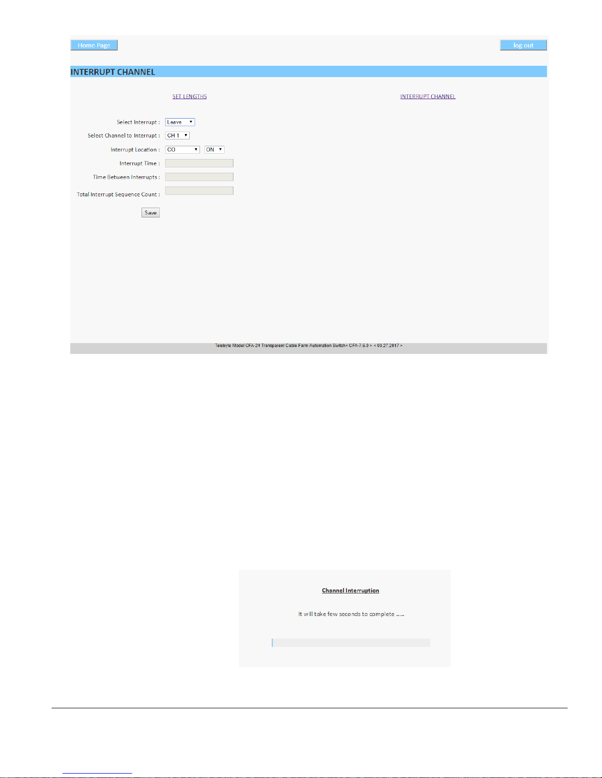
Model CFA-24 Transparent Cable Farm Automation Switch Reference Manual Page 54 of 78
Example Set Leave screen.
• Select Interrupt: Select the interrupt type of Microcut, Cut or Leave from the dropdown.
➢ An interrupt type of Cut, once started, can only be stopped by entering a “set interrupt off” remote
command from a second connection.
• Select Channel to Interrupt: using the dropdown select the one channel to which the interrupt will apply.
• Interrupt Location: select CO or CPE or CO & CPE (Standalone units only) from the dropdown.
• Interrupt Time:
o Microcuts: 5ms to 750ms
o Cuts: 2s to 60s
• Time Between Interrupts: if the interruption is to be repeated, enter the number of seconds in-between each
interruption event (e.g., 1s to 31s for a micro-interruption).
• Total Interrupt Sequence Count: repeat the sequence until this length of time is reached.
• Save: click the Save button to begin the interruption. The progress bar is shown.
• When the sequence is complete, the Interrupt screen is shown.

Model CFA-24 Transparent Cable Farm Automation Switch Reference Manual Page 55 of 78
10.0 User Management
Access to interface selections can be controlled using the User Management option.
• Enter the static IP address of the Controller unit to access the Main screen. Select User Management.
The Main Screen.

Model CFA-24 Transparent Cable Farm Automation Switch Reference Manual Page 56 of 78
• Access Level for User:
o Full Access
o Installation Configuration Management
o Network Monitoring Screen
o Test Maintenance
o Set Allowable Line Lengths/Interrupts
• Save: click Save to make an immediate change to the security configuration.

Model CFA-24 Transparent Cable Farm Automation Switch Reference Manual Page 57 of 78
11.0 Upgrade Firmware
➢ Upgrading the firmware resets the Coordinate Matrix to the factory default settings (if the Retain
Current Settings box is not checked). Prior to performing this procedure, backup the Coordinate
Matrix settings (see Create Backup of Coordinate Matrix later in this document).
• This process can take as long as 50 minutes, depending on the connection speed on the CFA-24 network.
• Telebyte recommends the use of Google Chrome browser (version-11.0.9600.17937 & update versions -
11.0.22) for the most stability.
• Place the new firmware upgrade file on the remote PC.
• Enter the static IP address of the unit to access the Main screen.
• Select Upgrade Firmware.
The Main Screen. Software version shown is an example only.
• The Upgrade Firmware screen is displayed.
The Upgrade Firmware screen. Software version shown is an example only.
• Select Firmware File: click Choose File to search for and select the remote PC that contains the firmware file.
The filename of CFA-x.x.x.telebyte (where x.x.x represents the new firmware version) should be available for
selection.
• Check off Retain Current Settings: Retains all settings from the Initial Configuration Management, including
IP settings, Operational Mode, and Coordinate Matrix.
• UPGRADE: Click the UPGRADE button to begin the firmware upgrade. The following screen is shown:
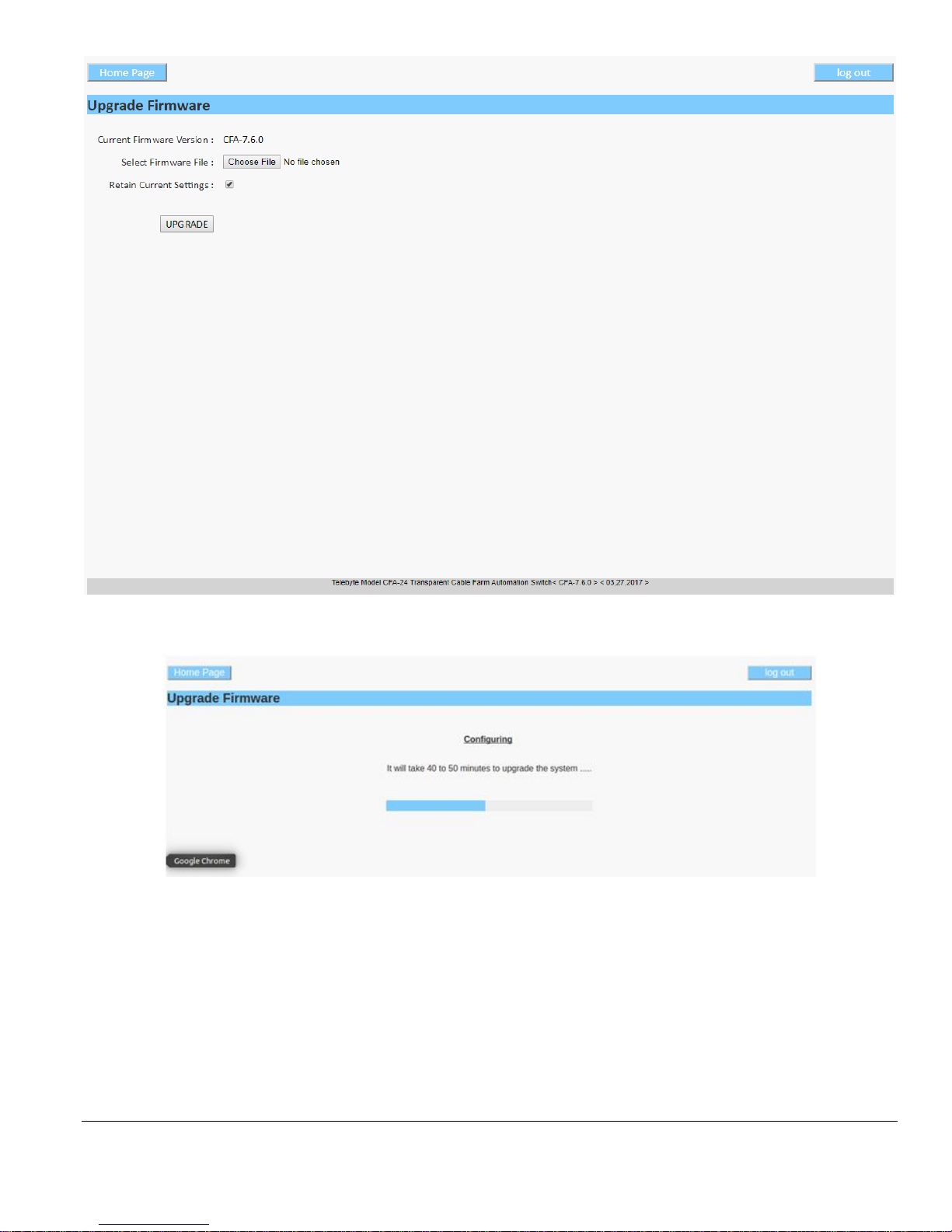
Model CFA-24 Transparent Cable Farm Automation Switch Reference Manual Page 58 of 78
• This above screen displays for approximately10 minutes. The following screen is then shown:
• The above screen may not display “. . . 40 to 50 minutes . . .” but instead may show “this process may take a
few minutes.”
• A progress bar is displayed. The message “Firmware upgraded successfully” is shown when the firmware
upgrade is complete. See the following screen for an example.

Model CFA-24 Transparent Cable Farm Automation Switch Reference Manual Page 59 of 78
• Press OK and wait 3 minutes for the system to reboot. During this time, the web browser displays a message
indicating the web page is unavailable.
• When the reboot is complete, type the IP address of the CFA system into the web browser to reestablish the
connection. The Main screen appears with the new version number displayed at the bottom of the screen.
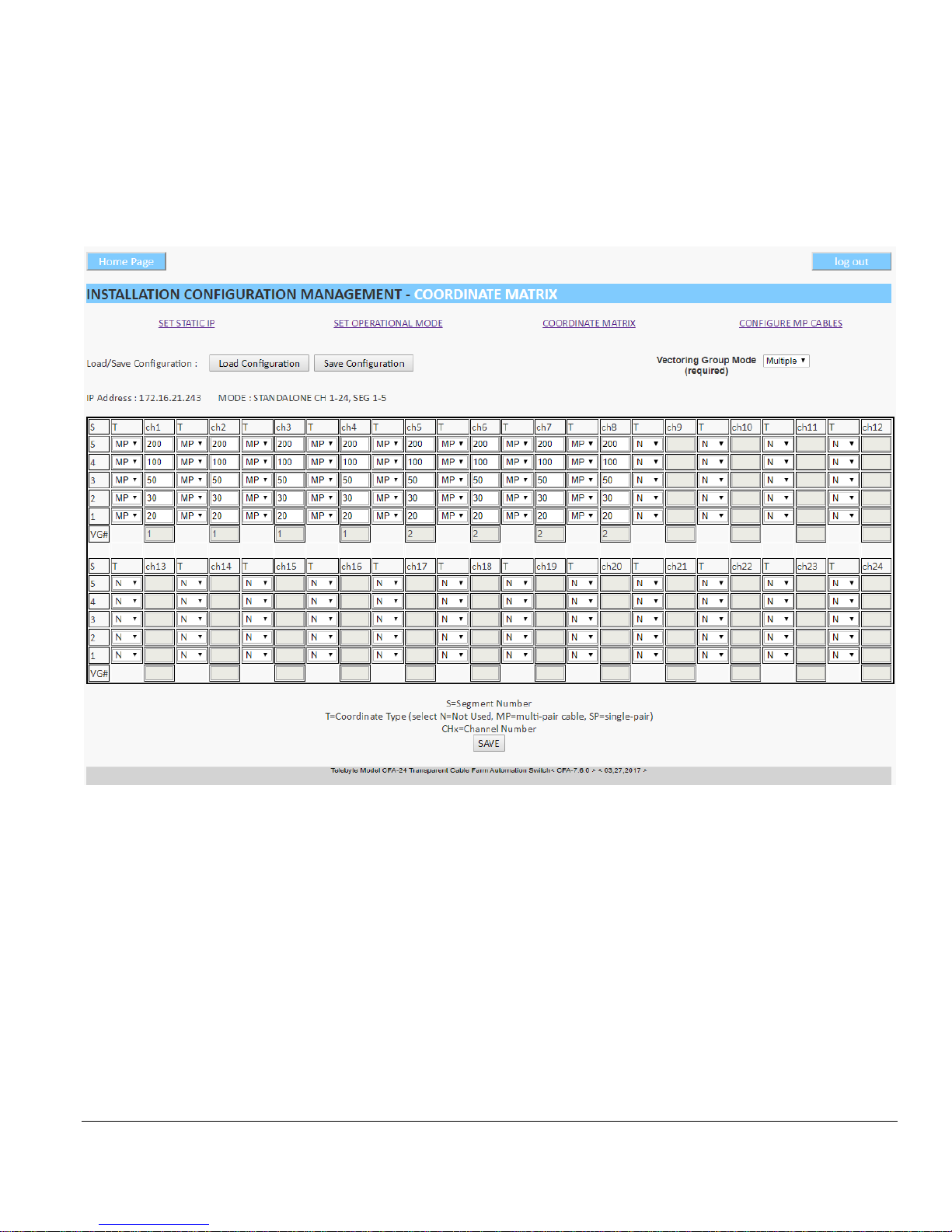
Model CFA-24 Transparent Cable Farm Automation Switch Reference Manual Page 60 of 78
12.0 Create Backup of Coordinate Matrix
Telebyte recommends the user create a backup of all Coordinate Matrixes in the CFA network before performing a
firmware upgrade. The firmware upgrade procedure resets the Coordinate Matrix settings to the default. Once created,
the backup may be uploaded after the upgrade is complete.
1. On each CFA-24 in the CFA network, navigate to the Installation Configuration Management – Coordinate
Matrix screen. The Coordinate Matrix is shown.
Load Configuration: Click to select a .bin Coordinate Matrix Configuration file and upload it.
Save Configuration: Click to download and save a copy of the current Coordinate Matrix Configuration file. The
default location for saving this file is the Downloads folder of the remote PC under the filename “Coordinatematrix.bin.”
This filename can be renamed as well as saved in a different location, if desired.

Model CFA-24 Transparent Cable Farm Automation Switch Reference Manual Page 61 of 78
13.0 Technical Support
Technical support is available on the web by going to http://www.telebytebroadband.com/main/support_index.asp.
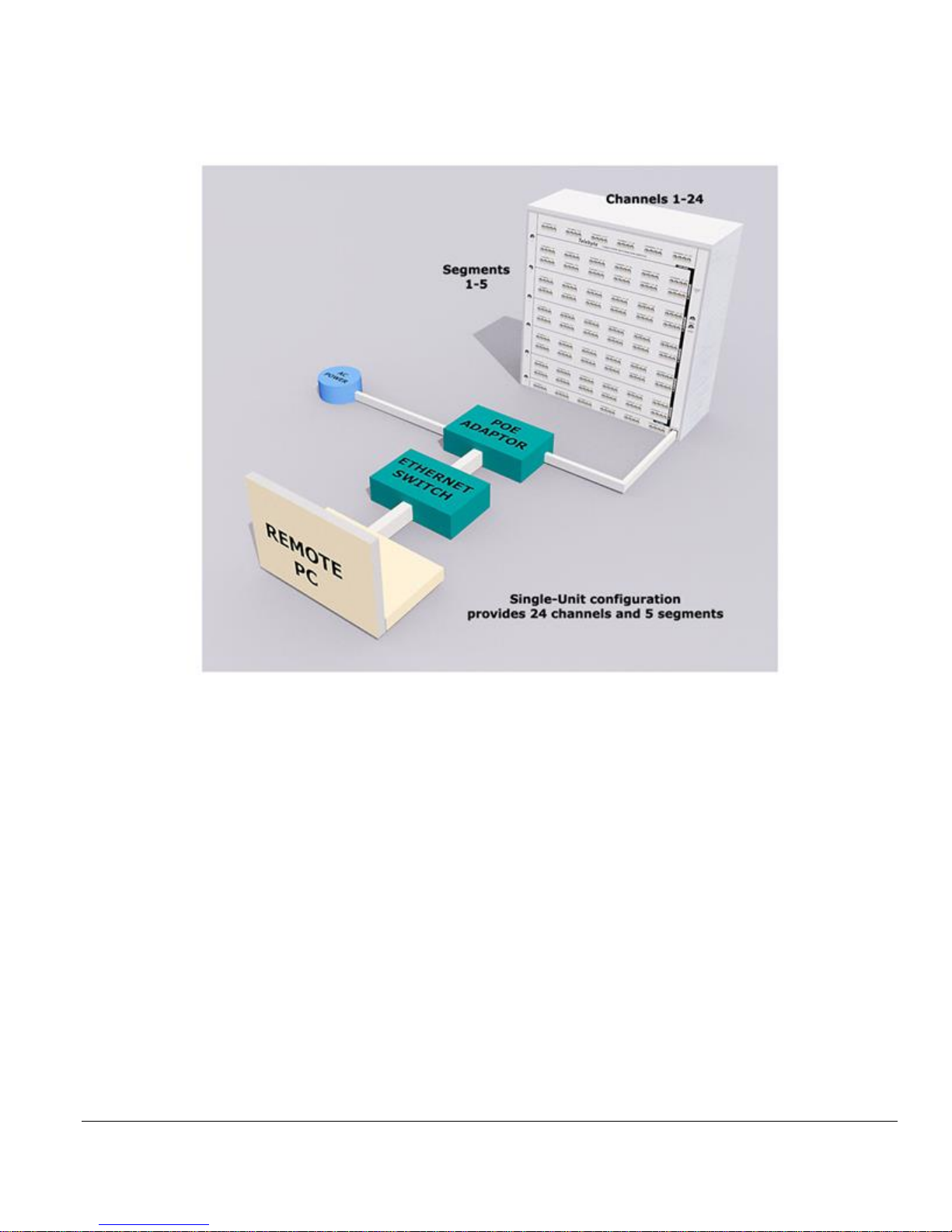
Model CFA-24 Transparent Cable Farm Automation Switch Reference Manual Page 62 of 78
Appendix A – Configuration Example Diagrams
5 Segments/24 Channels
A single Controller unit provides 5 segments and 24 channels. The POE adaptor connects to an Ethernet switch, AC
power and the CFA-24 unit. The Ethernet switch connects to the remote PC.
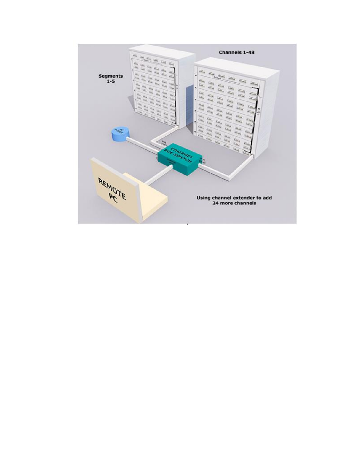
Model CFA-24 Transparent Cable Farm Automation Switch Reference Manual Page 63 of 78
5 Segments/48 Channels
The example above shows 1 controller and 1 channel extender unit. This adds 24 more channels for a total of 5
segments across 48 channels. The Ethernet POE switch connects the remote PC, AC power and 2 CFA-24 units. Note
the CFA-24 units use the POE ports while the remote PC uses the Ethernet port.

Model CFA-24 Transparent Cable Farm Automation Switch Reference Manual Page 64 of 78
10 Segments/48 Channels
The example above shows 1 Controller unit, 1 channel extender, 1 segment extender and 1 channel/segment extender.
This provides a total of 10 segments across 48 channels. The Ethernet POE switch connects the remote PC (using the
Ethernet port), AC power and 4 CFA-24 units (using the POE ports).
Model CFA-24 Transparent Cable Farm Automation Switch Reference Manual Page 65 of 78
Appendix B - Remote Commands
• Please note: configuring the static IP address should be done using the web browser interface.
• The word “ACCEPTED” is displayed when commands are accepted.
Access via Remote Telnet and SSH Connections
The system prompts the user for the following login ID and password (valid from version 6.4.1 and later):
Login: telebyte
Password: telebyte
Shutdown via Remote Telnet and SSH Connections
For systems shipped before 1/1/2016, once the CFA-24 is powered on, it is very important that
the user does not unplug the POE Ethernet cable from the CFA-24. Doing so can cause the
operating system to become corrupted. The CFA-24 should be shut down properly using the
SHUTDOWN button on the Main screen of the web browser interface or the Remote Command
“shutdown” described below. This is no longer required on newer units which are able to perform a
self shutdown should a power failure occur or the Ethernet cable come loose.
shutdown
Command: shutdown –h now
Note: Allow 20 seconds to stop all processes before unplugging the system.
reboot
Command: reboot
!
IMPORTANT

Model CFA-24 Transparent Cable Farm Automation Switch Reference Manual Page 66 of 78
Show Command
show -h
Displays a help menu with CFA “show” commands
show system netif
Shows Ethernet address of current CFA unit.
Example
Command: show system netif
Response:
ACCEPTED show system netif
“ip" 172.16.21.241 "subnet" 255.255.255.0 "gateway" 172.16.21.1
show system software
Shows software information of current CFA unit.
Example
Command: show system software
Response:
ACCEPTED show system software
"software" CFA-6.9.0
"Date" 2016-02-17 "Time" 11-24-50
show length <line>
Shows current line length for a specified channel or range of channels
Valid Values:
<line> either a single channel or a range of channels separated by a colon (e.g., 2:12)
Example
Command: ACCEPTED show length 1:2
Response: channel 1 Length 100
channel 2 is terminated

Model CFA-24 Transparent Cable Farm Automation Switch Reference Manual Page 67 of 78
show term <line>
Shows current termination status of specified channel or channel range.
Valid Values:
<line> either a single channel or a range of channels separated by a colon (e.g., 2:12)
Example
Command: ACCEPTED show term 1:2
Response: channel 1 term : No
channel 2 term : Yes
$ show ncl vg<n>
Show the included and non-included segments of specified Non-Colocated vectoring groups.
<n> the vectoring group, or range of vectoring groups separated by a colon.
Example: show status of segments in Vectoring Group 1
Command: $ show ncl vg1:vg2
Response: ACCEPTED show ncl vg1:vg2
Status of VG1:
1c
2c
3c
4u
5u
Status of vg2:
Vectoring Group 2 is COLOCATED (All segments are included in a Colocated VG)
In the example above, c represents an included segment and u represents a segment that is no included. This is equal
to (c)hecked and (u)nchecked segments in the Test Maintenance screen.

Model CFA-24 Transparent Cable Farm Automation Switch Reference Manual Page 68 of 78
show leave <line>
Displays the status of the disorderly leave interrupt for both CO and CPE of any single channel or channel range or
channel group.
Valid Values:
<line> either a single channel or a range of channels separated by a colon (e.g., 2:12)
Example
Command: show leave 1,9,17
Response:
ACCEPTED show leave 1,9,17
Channel 1 co on cpe off
Channel 9 co on cpe off
Channel 17 co on cpe off
show allow <line>
Display the list of allowable loop lengths for a specific channel.
Valid Values:
<line> a single channel number
Example
Command: show allow 1
Response:
ACCEPTED show allow 1
0
25
75
175
375
475
term

Model CFA-24 Transparent Cable Farm Automation Switch Reference Manual Page 69 of 78
show vg details
Display the details of vectoring groups in the system.
Example
Command: show vg details
Response:
ACCEPTED show vg details
Number of Vectoring Groups: 2
Vectoring Group 1:
Type: non-colocated
Number of channels in VG1: 12
Channels in VG1: 1, 2, 3, 4, 5, 6, 7, 8, 9, 10, 11, 12
Vectoring Group 2:
Type: colocated
Number of channels in VG2: 12
Channels in VG2: 13, 14, 15, 16, 17, 18, 19, 20, 21, 22, 23, 24
Set Command
set -h
Displays a help menu with CFA “set” commands
set length <line> <length>
Sets the total line length for a specified channel or range of channels.
Valid Values:
<line> either a single channel or a range of channels separated by a colon (e.g., 2:12)
<length> any allowable length established during CFA configuration
Example
Command: set length 1 50
Response: CFA-24:~$set length 1 50
ACCEPTED set length 1 50
Length 50 saved for channel 1

Model CFA-24 Transparent Cable Farm Automation Switch Reference Manual Page 70 of 78
set term <line><yes|no>
Terminates a specified channel or range of channels.
Valid Values:
<line> either a single channel or a range of channels separated by a colon (e.g., 2:12)
<yes/no> enter yes to terminate the line or no to un-terminate the line and reestablish the previous loop length
Example
Command: set term 1:3 yes
Response:
ACCEPTED set term 1:3 yes
channel 1 is terminated
channel 2 is terminated
channel 3 is terminated
set termloc <line><co|cpe|both|none>
Terminates a channel independently on either the CO, CPE or both sides.
Valid Values:
<line> a single channel number
<co|cpe|both|none> enter the side or sides of the channel to terminate. Entering <both> has the same functionality as
the command “set term <line> yes”. Entering <none> restores the previous relay setting before the “set termloc”
command was executed.
Example:
Command: set termloc 1 cpe
Response:
ACCEPTED set termloc 1 cpe
Channel 1 is terminated on CPE side

Model CFA-24 Transparent Cable Farm Automation Switch Reference Manual Page 71 of 78
set microcut <line> <location> <open time in ms> <period> <count>
Valid Values:
<line> is only a single channel number (Only single channel can be interrupted)
<location> co, cpe or both
<open time in ms> is the length of time for which the line is cut in milliseconds.
Allowable Range: 5 ms to 750 ms
Increments: 5 ms.
<period> is the time of the complete cycle. The cycle consists of the interrupt time and the closed time.
Periods are only in seconds.
Allowable Range: 1 s to 31 s
Increments: 1 s
<count> represents the number of line on/off events to execute.
Allowable Range: 1 to 255 counts
Increments: 1 count
Example
Command: set microcut 1 co 5 1 5
Response: CFA-24:~$set microcut 1 co 5 1 5
ACCEPTED set microcut 1 co 5 1 5
Channel(1) interrupt running
CFA-24:~$

Model CFA-24 Transparent Cable Farm Automation Switch Reference Manual Page 72 of 78
set cut <line> <location> <open time in seconds> <period> <count>
Valid Values
<line> is only a single channel number or range of channels (Only single channel can be interrupted)
<location> co, cpe or both
<open time in seconds> is the length of time for which the line is open in seconds
Allowable Range: 2 s to 60 s
Increments: 1 s
<period> is the time of the complete cycle. The cycle consists of the interrupt time and the closed time.
Periods are only in seconds.
Allowable Range: 1 s to 180 s
Increments: 1 s
<count>It represents the number of line on/off events to execute.
Allowable Range (Cut): 1 to 40 counts
Increments: 1 count
Example
Command: set cut 1 co 1 2 5
Response: CFA-24:~$
ACCEPTED set cut 1 co 1 2 5
Channel(1) interrupt running
CFA-24:~$
Note: the $ prompt is returned once the interrupt is complete.
set interrupt off
Execute this command to turn off a cut and microcut type of interrupt currently running.
➢ While microcut or cut interrupt is running, this command must be entered from a second Telnet
session.

Model CFA-24 Transparent Cable Farm Automation Switch Reference Manual Page 73 of 78
$ set leave <line> <location> <on|off>
Sets a disorderly leave of a line or group of lines on the CPE or CO side of the loop.
<line> either a single channel or a range of channels separated by a colon (e.g., 2:12), or specific channels
separated by a comma
<location> co or cpe side of the loop
<on | off> enables or disables an open
Example 1: set leave on line 1, co side to on
Command: CFA-24:~$ set leave 1 co on (Sets a disorderly leave)
Response: ACCEPTED set leave 1 co on
Command: CFA-24:~$ set leave 1 co off (Reestablishes the line)
Response: ACCEPTED set leave 1 co off
Example 2: set leave on lines 1 to 24, co side to on
Command: CFA-24:~$ set leave 1:24 co on
Example 3: set leave on lines 1, 5, 9, 17, and 24, cpe side to on
Command: CFA-24:~$ set Leave 1,5,9,17,24 cpe on
set cl <vectoring group> colocated <on|off>
Defines one or more vectoring groups as Colocated or Non-Colocated. Equivalent of checking the Colocated checkbox
on the Test Maintenance screen.
<vectoring group> a single vectoring group or a range of vectoring groups separated by a colon (e.g., vg1:vg5)
colocated <off|on> where on defines the vectoring group(s) as Colocated; OR where off defines the vectoring
group(s) as Non-Colocated.
Example
Command: set cl vg1:vg5 on
Response: ACCEPTED set cl vg1:vg5 on

Model CFA-24 Transparent Cable Farm Automation Switch Reference Manual Page 74 of 78
set ncl <vectoring group> <segment><checked|unchecked>
Checks or unchecks segments in one or more vectoring groups. Equivalent of checking the same segment in the “Check
to Include” column on the Test Maintenance screen.
<vectoring group> a single vectoring group or a range of vectoring groups separated by a colon (e.g., vg1:vg5)
<segment> a segment number
Allowable values: 1, 2, 3, 4 or 5
<checked|unchecked> changes the status of the segment to checked or unchecked.
Allowable values: (u)nchecked or (c)hecked.
Example
Command: set ncl vg1 1c 2c 3c 4c 5u
Response: ACCEPTED set ncl vg1

Model CFA-24 Transparent Cable Farm Automation Switch Reference Manual Page 75 of 78
Appendix C – ID-337 Screen Examples
Example – Using Two Vectoring Groups, 4 Channels Each
Coordinate Matrix (8 Channels)
Configure MP Cables (2 Vectoring Groups)

Model CFA-24 Transparent Cable Farm Automation Switch Reference Manual Page 76 of 78
Test Maintenance (All Segments Selected)
Set Lengths (2 Different Lengths for Each Vectoring Group)

Model CFA-24 Transparent Cable Farm Automation Switch Reference Manual Page 77 of 78
Appendix D –Recommended Cable Segment Lengths
ID-337
Telebyte recommends installation of the following cable segment lengths, in the order shown:
Segment 5 200m
Segment 4 100m
Segment 3 50m
Segment 2 30m
Segment 1 20m
The Coordinate Type of MP should be assigned in the Coordinate Matrix.
The above allows selection of the 20, 50, 100, 200 and 400 meters in the standard.
TR-249
Telebyte recommends installation of the following cable segment lengths:
Segment 5 150m
Segment 4 150m
Segment 3 150m
Segment 2 150m
Segment 1 150m
The Coordinate Type of MP should be assigned in the Coordinate Matrix.
The above allows selection of the 150, 300, 450, 600 and 750 meters in the standard.

Model CFA-24 Transparent Cable Farm Automation Switch Reference Manual Page 78 of 78
Customer Care
Warranty
One-year Warranty
• Telebyte will furnish parts and labor for the repair or replacement of products found by Telebyte
to be defective in material or workmanship during the warranty period.
1
Extended Customer Care
Refer to the Customer Care section of the Telebyte web site for the most current information on extended
warranty and calibration contracts
2,3,4:
http://www.telebytebroadband.com/customercare.html
Disclaimer of Warranties and Other Terms and Conditions
1
TELEBYTE, INC. warrants its broadband simulation equipment to be free from defects in material and workmanship, under normal and proper
use and in its unmodified condition, for 12-months, starting on the date it is delivered for use. TELEBYTE’S sole obligation under this warranty
shall be to furnish parts and labor for the repair or replacement of products found by TELEBYTE to be defective in material or workmanship
during the warranty period. Warranty repairs will be performed at the point of manufacture. Equipment approved for return for warranty service
shall be returned F.O.B. TELEBYTE factory and will be redelivered by TELEBYTE freight prepaid, except for non-continental U.S.A. locations.
These deliveries will be sent COD freight and import/export charges.
2
The customer is responsible for freight and customs charges when shipping products to and from Telebyte for calibration services.
3
You must purchase the extended warranty at the time of purchase or during the initial warranty period.
4
You must purchase the calibration contract at the time of purchase or during the initial warranty period. The above warranty is in lieu of all other
warranties, expressed or implied, statutory or otherwise, including any implied warranty of merchantability or fitness for a particular purpose.
TELEBYTE shall not be liable for any damages sustained by reseller or any other party arising from or relating to any equipment failure, including
but not limited to consequential damages, nor shall TELEBYTE have any liability for delays in replacement or repair of equipment.
 Loading...