

Page 1

“Results You Can Count On”
Dual Output AWGN Generator Line Module
Model 458-AWGN2
Rev. -
Date of Publication: 04/15/11
Page 2

Customer Support
Thank you for your purchase of the Telebyte Model 458-AWGN2 Dual Output AWGN
Generator Line Module. This product is designed to inject Additive White Gaussian Noise
(AWGN) on the CO and/or CPE side of a loop simulator installed in one of Telebyte’s chassis
or onto real cable.
Contact Information:
Telephone E-mail/Internet
General: 631-423-3232 [email protected]
Technical support: 800-835-3298 [email protected]
Fax: 631-385-8184 www.telebytebroadband.com
Mail
Telebyte, Inc.
355 Marcus Blvd
Hauppauge, NY 11788
Page 3
Warranty
Included With Your Purchase
One-year Warranty
• Telebyte will furnish parts and labor for the repair or replacement of products found by Telebyte to be defective
in material or workmanship during the warranty period.
One-year Calibration (where applicable)
• One N.I.S.T. traceable calibration on the first-year anniversary of the product ship date.2
• Calibration report to ensure traceability.
Extended Customer Care
There are two options available. Our three-year extended warranty extends the original warranty by an additional 36
months and the three-year calibration contract provides 36 additional months of calibration.
1
Three-Year Extended Warranty
You can extend the original one-year warranty that
comes with your product by purchasing the Three-Year
Extended Warranty.3
Features:
· Telebyte will furnish parts and labor for the repair or
Three-Year Calibration Contract (where applicable)
Extended calibration is available through the Three-Year
Calibration Contract.4
Features:
·
Yearly N.I.S.T. traceable calibrations, each on the
second, third and fourth anniversary of the ship date.
2
replacement of products found by Telebyte to be
defective in material or workmanship during the
warranty period.1
· Report to ensure traceability.
· Automatic notification when calibration of your product is
due.
Disclaimer of Warranties and Other Terms and Conditions
1
TELEBYTE, INC. warrants its broadband simulation equipment to be free from defects in material and workmanship, under normal and proper use
and in its unmodified condition, for 12-months, starting on the date it is delivered for use. TELEBYTE’S sole obligation under this warranty shall be to
furnish parts and labor for the repair or replacement of products found by TELEBYTE to be defective in material or workmanship during the warranty
period. Warranty repairs will be performed at the point of manufacture. Equipment approved for return for warranty service shall be returned F.O.B.
TELEBYTE factory and will be redelivered by TELEBYTE freight prepaid, except for non-continental U.S.A. locations. These delive ries will be sent
COD freight and import/export charges.
2
The customer is responsible for freight and customs charges when shipping products to and from Telebyte for calibration services.
3
You must purchase the extended warranty at the time of purchase or during the initial warranty period.
4
You must purchase the calibration contract at the time of purchase or during the initial warranty period. The above warranty is in lieu of all other
warranties, expressed or implied, statutory or otherwise, including any implied warranty of merchantability or fitness for a particular purpose.
TELEBYTE shall not be liable for any damages sustained by reseller or any other party arising from or relating to any equipment failure, including but
not limited to consequential damages, nor shall TELEBYTE have any liability for delays in replacement or repair of equipment.
Page 4

Equipment Returns
Out of warranty equipment may be returned, prepaid, to the Hauppauge, N.Y.
customer service facility. Return shipping charges will be billed to the customer.
The repaired unit will have a 90-day warranty. In those cases where "no trouble"
is found, a reduced charge will be billed to cover handling, testing, and
packaging. Whether in or out of warranty, a Return Material Authorization
number (RMA) is required and may be obtained by going to
www.telebytebroadband.com and opening a technical support case.
Please be sure to reference the RMA number on the outside container.
Page 5

Table of Contents
1.0 Introduction .................................................................................................................................. 1-1
2.0 Specifications ............................................................................................................................... 2-1
2.1 458-AWGN2 ................................................................................................................................. 2-1
2.2 458-3SLB ..................................................................................................................................... 2-1
2.3 458-CC-16/458-CM ...................................................................................................................... 2-2
3.0 Control .......................................................................................................................................... 3-1
3.1.1 RS-232 (Serial Port) Remote Commands ................................................................................. 3-1
3.1.2 GPIB Remote Command ........................................................................................................... 3-2
3.2 Graphical User Interface ............................................................................................................ 3-3
3.3 LCD Display ............................................................................................................................... 3-3
Page 6

1.0 Introduction
The Model 458-AWGN2 is the ideal solution for injecting Additive White Gaussian Noise (AWGN) for
ADSL, ADSL2, ADSL2+, and VDSL2 chip/modem/DSLAM testing applications. The user may add
AWGN on the CO and/or CPE side, depending on their application. The 458-AWGN2 allows for
common or independent noise levels on both sides. This line module produces a flat Power Spectral
Density (PSD) over bandwidths from 20 kHz to 30 MHz.
This module is plugged into our Model 458-3SLB (3-Slot) or 458-CC-16 (16 Slot) chassis where
settings are controlled by a convenient keypad located on the front, RS-232, Ethernet or IEEE488(GPIB). The modular design of Telebyte’s products allows the 458-AWGN2 to be combined with
other line modules for a wide variety of test configurations. This module can also be used to inject
AWGN onto real cable.
Features:
Bandwidth 20 kHz to 30 MHz
Inject AWGN onto real cable or local loop simulator
Solution for injecting AWGN for ADSL, ADSL2, ADSL2+, & VDSL2
chip/modem/DSLAM testing
Plugs into our Model 458-CC-16 (16-slot) or 458-3SLB (3-Slot) chassis
AWGN levels can be controlled manually via front panel of chassis, or remotely via RS-232,
Ethernet or IEEE-488 (GPIB)
458 Universal GUI software for control from a remote PC
White Noise (AWGN) Generator (-90 dBm/Hz to -145 dBm/Hz)
Model 458-AWGN2 Dual Output AWGN Generat or Line Module Page 1-1
Page 7
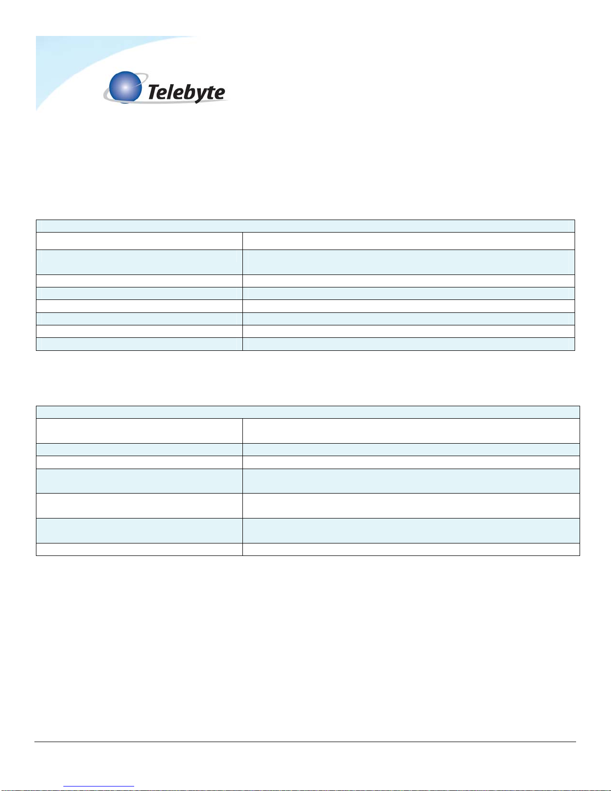
2.0 Specifications
2.1 458-AWGN2
Product Specifications
Simulation Additive White Gaussian Noise (AWGN)
Bandwidth Flat Power Spectral Density (PSD) over bandwidths from
20 kHz to 30 MHz
AWGN Crest Factor ≥ 5
Output Impedance 4kΩ Minimum (20 kHz to 30 MHz)
White Noise (AWGN) Generator -90 dBm/Hz to -145 dBm/Hz in 0.25-dBm increments
Maximum Voltage Tip – Ring 200 V
Output Mode Differential, balanced
Connectors 4 RJ-45’s on front (2 for CO side, 2 for CPE side of loop)
2.2 458-3SLB
Product Specifications (Chassis and Control Module)
Controls Keypad for setting loop lengths and IEEE-488 address, RS-232,
or Ethernet communication parameters.
Indicators Backlit LCD display of line length and set up parameters.
Power 88 to 264 VAC, 50 or 60 Hz
Size [2U] 19 in W x 22 in D x 3.47 in H (482.6 mm W x 558.8 mm D
x 88.1 mm H)
Environmental Operating: +32 F to +122 F (0 to +50 degrees C)
Storage: 0 to 95% relative humidity (non-condensing)
Remote Control Connectors RS-232: DB9 female (DCE); GPIB:IEEE488 24-pin connector.
Ethernet: RJ-45
Plug-In Compatibility Accepts one, two or three 458 Line Modules or one 458-RT
Model 458-AWGN2 Dual Output AWGN Generat or Line Module Page 2-1
Page 8
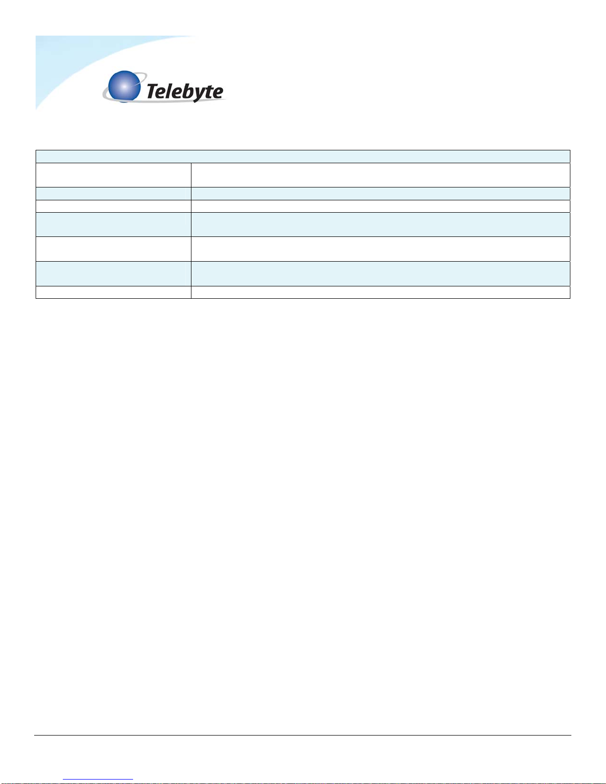
2.3 458-CC-16/458-CM
Product Specifications 458-CC-16 (16-Slot Chassis) & 458-CM (sold separately)
Controls Keypad for setting loop lengths and IEEE-488 address, RS-232, or
Ethernet communication parameters.
Indicators Backlit LCD display of line length and set up parameters.
Power 100 - 240 VAC, 50 or 60 Hz
Size [7U] 19 in W x 22 in D x 12.22 in H
(482.6 mm W x 558.8 mm D x 310.4 mm H)
Environmental Operating: +32 F to +122 F (0 to +50 degrees C)
Storage: 0 to 95% relative humidity (non-condensing)
Remote Control
Connectors
Plug-In Compatibility Accepts 1-16 458 Line Modules
RS-232: DB9 female (DCE); GPIB:IEEE488 24-pin connector. Ethernet:
RJ-45
Specifications are subject to change without notice. Made in USA.
Detailed information about the operation of the 458-3SLB and 458-CC-16/458-CM can be
found in the reference manuals for those products.
Model 458-AWGN2 Dual Output AWGN Generat or Line Module Page 2-2
Page 9

The Model 458-AWGN2 can be controlled three ways: via RS-232 and IEEE488 Remote
Commands, our GUI interface or the LCD display on the front panel of our 458-3SLB or 458CM.
Only information specific to the 458-AWGN2 is provided in this section. Ref er to the 458-
3SLB or 458-CC-16/458-CM manuals for additional control information.
3.1 Remote Commands
3.1.1 RS-232 (Serial Port) Remote Commands
Set Noise Mode/Level Command Values:
SL:M:NOISE:CPE:V or SL:M:NOISE:CO:V
Where,
SL = set length
M = module (slot) number 01 – 16 (458-CM) or 01-03 (458-3SLB)
NOISE = noise mode
CPE or CO = set noise for CPE or CO side of loop
V = AWGN values allowed – OFF or -90.00 to -145.00 (in 0.25 dBm/Hz steps)
Examples :
SL:02:NOISE:CPE:-123.75 = Set CPE noise source -123.75 dBm/Hz
SL:02:NOISE:CO:-95.00 = Set CO noise source to -95.00 dBm/Hz
SL:02:NOISE:CPE:OFF = Set CPE noise source to off
SL:02:NOISE:CO:OFF = Set CO noise source to off
Note: Upper or lower case text may be used
3.0 Control
Model 458-AWGN2 Dual Output AWGN Generat or Line Module Page 3-1
Page 10

3.1.2 GPIB (488) Remote Commands
Set Noise Mode/Level Command Values:
:SETCARD:LENGTH:M:NOISE:CO:V1,2 or :SETCARD:LENGTH:M:NOISE:CPE:V1,2
Where,
M = Module (slot) number 01 – 16 (458-CM), 01-03 (458-3SLB)
V1,2 = OFF or -90.00 to -145.00 level in 0.25 dBm/Hz steps.
Examples:
:SETCARD:LENGTH:02:NOISE:CPE:-123.75
= Set CPE noise source to -123.75 dBm/Hz.
:SETCARD:LENGTH:02:NOISE:CO:-95.00
= Set CO noise source to -95.00 dBm/Hz.
:SETCARD:LENGTH:02:NOISE:CPE:OFF
= Set CPE noise source to off.
:SETCARD:LENGTH:02:NOISE:CO:OFF
= Set CO noise source to off.
Note: Upper and lower case text can be used.
Read Noise Mode/Level Command Values:
READCARD:LENGTH:M:NOISE:CO or READCARD:LENGTH:M:NOISE:CPE
Where,
M = Module (slot) number 01 – 16 (458-CM), 01-03 (458-3SLB)
Example:
READCARD:LENGTH:02:NOISE:CO = Read CO noise level of module in slot 2
Model 458-AWGN2 Dual Output AWGN Generat or Line Module Page 3-2
Page 11

3.2 Graphical User Interface
Refer to the 458 Universal Graphical User Interface Reference Manual for more information.
3.3 LCD Display
Step One
Select the slot in the 458-3SLx (3-Slot) Chassis or 458-CC16/458-CM (16-Slot) Chassis
using the UP or DOWN arrows on the LCD display (e.g., when using our 3-slot chassis: slot
1 top, slot 2 middle, slot 3 bottom).
Step Two
Use Up arrow to select the CO or CPE noise.
Adjust the noise level using LEFT and RIGHT arrow buttons.
Model 458-AWGN2 Dual Output AWGN Generat or Line Module Page 3-3
 Loading...