

Page 1

ATLAS250
Installation Manual
Doc. DM698-I Ver. 2.0
June 2005
Page 2

ii
INDEX
1. Introduction........................................................................................................................ 1
1.1. Recycling and the Environment...............................................................................2
2. Installation..........................................................................................................................3
2.1. General installation conditions................................................................................ 3
2.2. Connection .............................................................................................................. 4
a) LAN Ethernet connection ........................................................................................ 4
b) WAN or external modem connection.......................................................................4
c) ISDN Connection ....................................................................................................5
d) Connecting for configuration..................................................................................6
2.3. Installation in a rack................................................................................................ 7
2.4. Switching on the device........................................................................................... 8
3. Description of the equipment.............................................................................................. 9
3.1. Description of the LEDs..........................................................................................10
3.2. Description of the microswitches ............................................................................11
a) Procedure to ignore the configuration....................................................................11
4. Appendices......................................................................................................................... 13
4.1. Smart Card ..............................................................................................................13
a) Description and insertion........................................................................................ 13
b) Viewing the content.................................................................................................13
c) Write........................................................................................................................15
d) Access Mode............................................................................................................15
e) Format..................................................................................................................... 17
4.2. Troubleshooting ......................................................................................................18
4.3. Updating the software and the configurations.........................................................19
a) Updating using FTP................................................................................................19
b) Updating via XModem ............................................................................................ 20
4.4. Connecting the connectors ...................................................................................... 23
• Twisted pair connections (RJ45) ......................................................................23
• ISDN Connector ............................................................................................... 23
• WAN Connector...............................................................................................23
• AUX port connections......................................................................................24
4.5. Technical Specifications.......................................................................................... 25
4.6. Installing PMC Cards.............................................................................................. 26
TELDAT S.A. reserves the right to make changes and improvements in the appropriate
features of the ATLAS250 in either software or hardware, modifying the specifications
of this manual without prior notice.
Page 3
ATLAS 250 – Installation Manual
1
Doc.DM698-I
Ver.2.0
1. Introduction
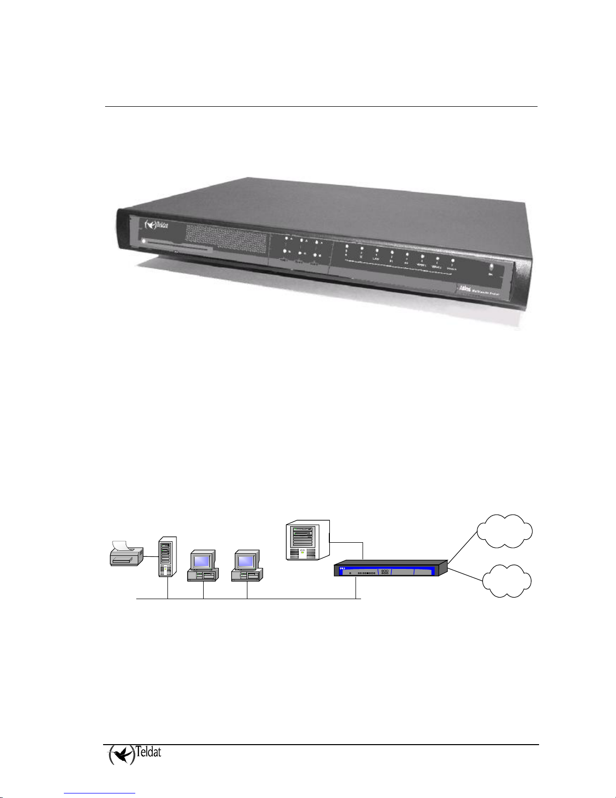
The Atlas250 is a device developed by TELDAT designed to adapt to most habitual teleprocess
networks scenarios: corporate, SME and personal environments (SOHO).
Through its WAN-LAN connections, this device provides router IP functions, supporting OSPF and
other dynamic routing protocols. The Atlas250 also presents a wide variety of connection possibilities
in SNA environments, from LLC2 and SDLC to QLLC conversion, that allow direct interconnection
of an Atlas250 to a local network without requiring a communication card in the server, and includes
SNA transport over IP networks through Data Link Switching (DLSw). This option permits the
transport network architecture to be standardized for TCP/IP.
As regards interfaces with public or private Wide Area Network (WAN), the Atlas250 permits access
to the Integrated Services Digital Network (ISDN) through a basic access through D and/or B channel.
In addition to the direct X.25 option, the possibility of FRAME-RELAY or PPP connections up to
speeds of 2 Mbps has been added.
The basic configuration consists of two LAN interfaces and three serial WAN interfaces and an ISDN
access. This can be amplified through the insertion of cards, both in Teldat format as well as in PMC
format (PCI Mezzanine Card), which can support encryption, voice over IP (VoIP), xDSL, etc.
hecho por M.A. Berrojo
Atlas
Teldat
ISDN
Public
Networks
FR/PPP/X25
Eth 10/100
Server
Printer
Server
Eth 10/100
Figure 1. User scenario example in teleprocess tasks
Page 4
ATLAS 250 – Installation Manual
2
Doc.DM698-I
Ver.2.0
hecho por M.A. Berrojo
Atlas
Teldat
ISDN
Public
Networks
FR/PPP/X25
Eth 10/100
Server
Printer
PSTN
FXSFXOFXS
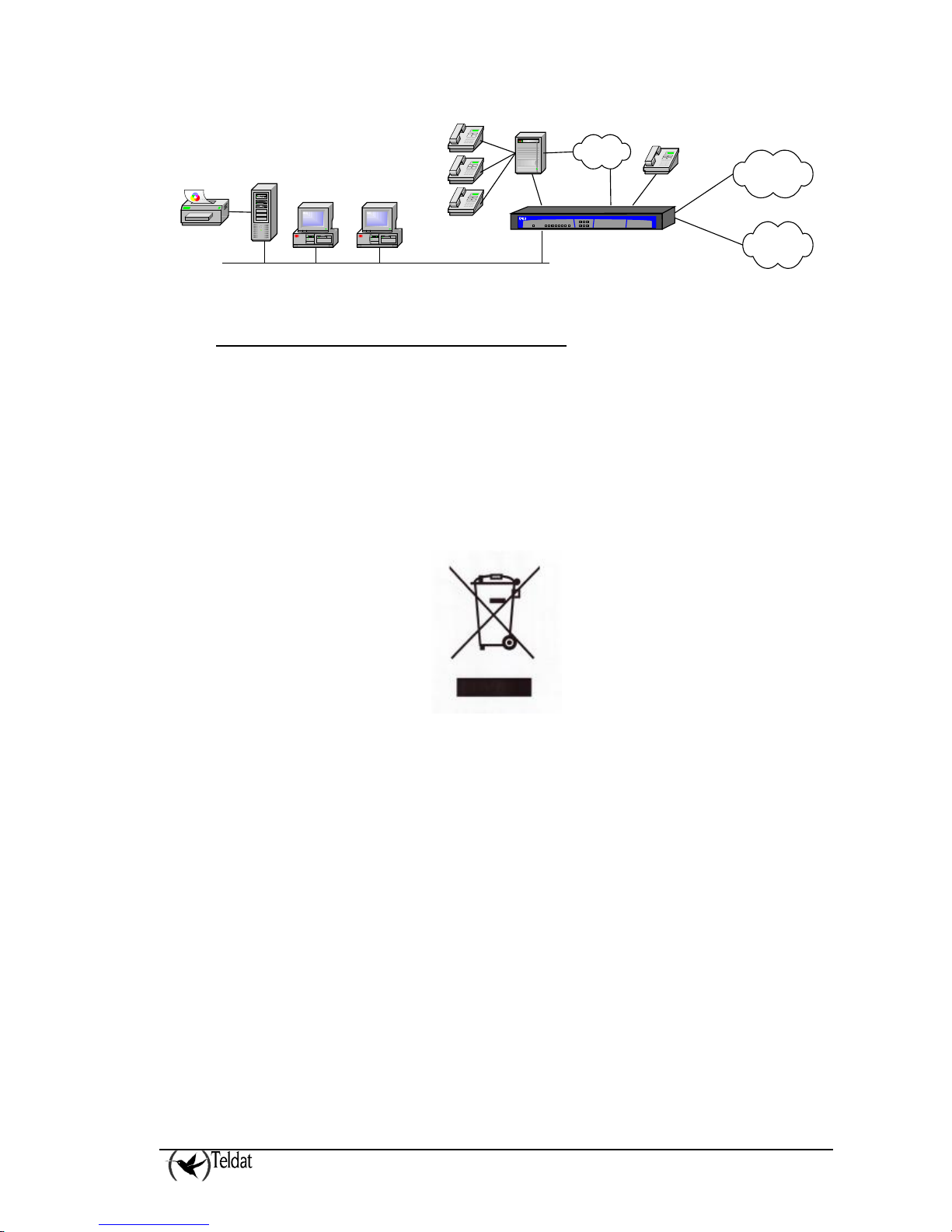
Figure 2. User scenario example with VoIP
1.1. Recycling and the Environment
Please do not under any circumstances throw away any Atlas250 with normal domestic waste. Ask
your local town hall for information on how to correctly dispose of them so protecting the
environment against e-waste. Always respect the current laws regarding waste material.
Anyone found violating the environmental laws will be subject to fines and any additional steps
established by law.
All the packing materials i.e. the cardboard box, plastic and any other packaging together with the
pieces making up an Atlas250 must be recycled complying with the current active laws regarding
recycling materials.
The above symbol with a cross over the rubbish container can be seen on the device. This means that
when a device reaches the end of its life, it must be taken to the official recycling/disposal centers
where it must be disposed of in an environmentally responsible manner and separate from normal
domestic waste.
Page 5

ATLAS 250 – Installation Manual
3
Doc.DM698-I
Ver.2.0
2. Installation
The Atlas250 multimedia router is designed to be both a desktop and a rack device. In either case, in
order to accomplish correct installation, please follow the recommendations given below:
BEFORE CONNECTING THE DEVICE PLEASE READ THE FOLLOWING
INSTRUCTIONS CAREFULLY.
2.1. General installation conditions
Workplace Conditions
Bear in mind the following recommendations:
1. Excessive cold and heat should be avoided, as should humidity and dust. Direct
exposure to sunlight should be avoided as well as other heat sources. The device should
not be placed amongst papers, magazines or other elements that could hinder natural air
circulation.
2. The device should not be placed very close to strong electromagnetic fields such as
speakers, engines, etc.
3. Knocks and/or strong vibrations should be avoided during transport, operation and
storage.
Power supply
The Atlas250 communications device does not require special conditions as regards voltage stability
or protection against power malfunctions as it is already protected.
To avoid electric shocks, residual current circulation and other unwanted effects, also affecting data
communications, the following is recommended:
• It is highly recommended that all interconnected data devices be plugged to THE
SAME GROUNDED POWER OUTLET, which should at the same time be of good
quality (lower than 10ohms).
• Whether the workplace is provided with an uninterrupted power supply system
(UPS), regulated supply or it is independent from the rest (such as lighting, etc.); it
is highly recommended that all data devices should be connected to the same power
source. This will avoid operating and premature aging problems of drivers and
other components.
WARNING: Electric supply current, telephone and communication cables are dangerous. To
prevent electric shock while installing, moving or opening the device covers, cables should
be disconnected and connected as follows.
To connect the Atlas250
To disconnect the Atlas250
• Make sure that the device power supply
switch is OFF
• Switch off the device.
• Connect all the data cables. • Disconnect the power supply cable
• Connect the power supply cable. • Disconnect the data cables.
• Switch on the device.
Page 6
ATLAS 250 – Installation Manual
4
Doc.DM698-I
Ver.2.0
2.2. Connection
a) LAN Ethernet connection
The LAN interface has two female RJ45 connectors in order to connect to the Ethernet 10BaseT /
100BaseT networks through shielded twisted pairs (STP) or unshielded (UTP) cables. These cables
are not supplied with the equipment; please consult your supplier with regard to this.
Depending on the design of the Network, the connection is carried out through a HUB or directly to
another terminal device Ethernet interface through a crossover cable (please consult your supplier for
information on crossover Ethernet cables).
b) WAN or external modem connection
The DTE/DCE multistandard serial interfaces have a DB25 female connector in order to connect to an
external modem or for connection to X.25, Frame Relay networks, etc.
Depending on the type of connection established, a different type of cable will be needed. This cable
can be supplied by Teldat if you wish.
On the underside on the device, there is a flap providing access to the sockets in order to insert the
V.24 DTE/DCE, V.35 DTE/DCE, and X.21 DTE/DCE drivers. These drivers are not multi-
purpose. The configuration for the operation mode is carried out by inverting the position of the
driver (this appears labeled as “T” indicating that this acts as terminal, and “M” indicating modem
functions). The operation mode is that indicated by the label closest to the connector.
La The default configuration for the drivers (on leaving the factory) is indicated on a
label located on the underside of the device, close to the drivers access flap.
In the below figure you can see a given drivers configuration. WAN 1 operates in DCE mode and
WAN 2 in DTE mode.
WAN 2 WAN 1
T
M
T
M
Figure 3. Situation of the drivers depending on operating mode
Page 7
ATLAS 250 – Installation Manual
5
Doc.DM698-I
Ver.2.0
c) ISDN Connection
The ISDN interface presents an RJ45 female connector to connector the 4-wire S bus coming from the
ISDN network terminator (NT1 or TR1).
You can use a flat cable with RJ45 male connectors, provided with the device for connection purposes.
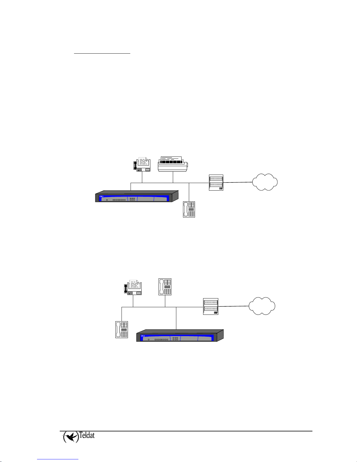
Passive-Bus terminal resistances
The Atlas250 routers have a pushbutton (labeled as “TERM”) in order to connect the BUS-S
termination resistances. The placing of these terminal resistances in the correct position is important
as contrariwise this can lead to errors in data (or voice), particularly if the “S” bus line is long. On
leaving the factory, the pushbutton, by default, is in the “ON” position.
• The only or last terminal in the ISDN “S” bus
The “TERM” pushbutton must be in the ON position if the router is the only element connected
to the network terminal (NT1, TR1, etc) or is in the last position on the ISDN “S” bus.
hecho por M.A. Berrojo
Atlas
Teldat
NT1 / TR1
S interface
(4 wires)
ISDN
U interface
(2 wires)
Figure 4. Location as the only or last terminal
• Intermediate position in the ISDN “S” bus
The “TERM” pushbutton must be in the OFF position if the router occupies an intermediate
position in the ISDN “S” bus.
hecho por M.A. Berrojo
Atlas
Teldat
NT1 / TR1
S interface
(4 wires)
ISDN
U interface
(2 wires)
Figure 5. Location in an intermediate position in the bus
Page 8
ATLAS 250 – Installation Manual
6
Doc.DM698-I
Ver.2.0
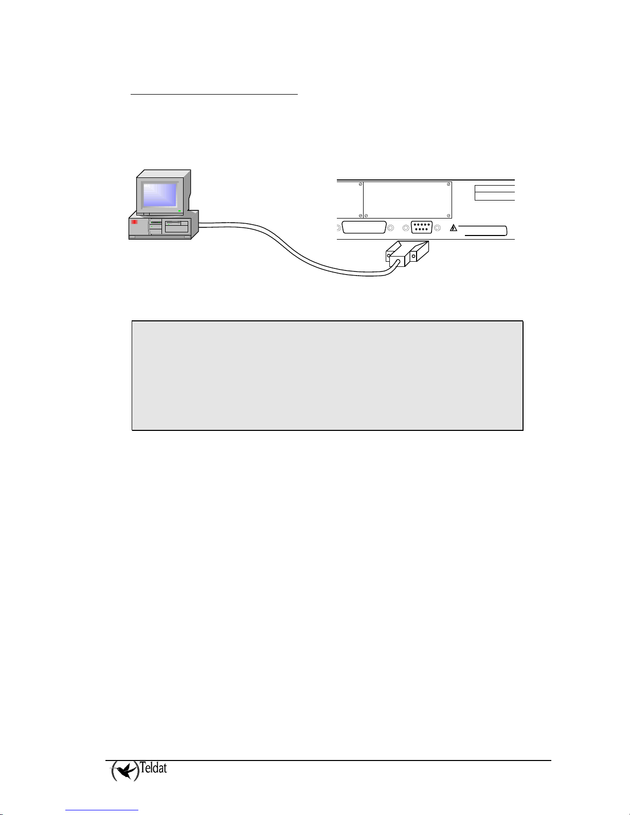
d) Connecting for configuration
The Atlas250 routers have a DB-9 female connector on the rear panel referred to as “AUX” which
provides access to the device local console for configuration and monitoring purposes. In order to use
this, you must connect the “AUX” port to an asynchronous terminal (or to a PC with terminal
emulation).
COM
To prevent electric shock,
do not remove cover.
CAUTION!
100-240 V~;1-0.5 A
47-63 Hz
∼
AC INPUT
WAN 1 AUX.
SLOT 1
Computer
Figure 6. Connection for configuration/monitoring via console
Configuration for the terminal must be:
- Speed: 9600 bps
- Eight data bits
- No parity bit
- One stop bit
- No type of flow control
Also expressed as 9600 8N1. The connection to the configuration port can be carried out with DB-9
female-DB-9 male cable provided with the equipment. In cases where the asynchronous terminal has
DB25 connectors, you must use an additional DB9F-DB25F adapter (not included with the
equipment).
This assembly can also be used to update the device code. For further information, please consult
section 4.3 “Updating the software and the configurations”.
Page 9
ATLAS 250 – Installation Manual
7
Doc.DM698-I
Ver.2.0
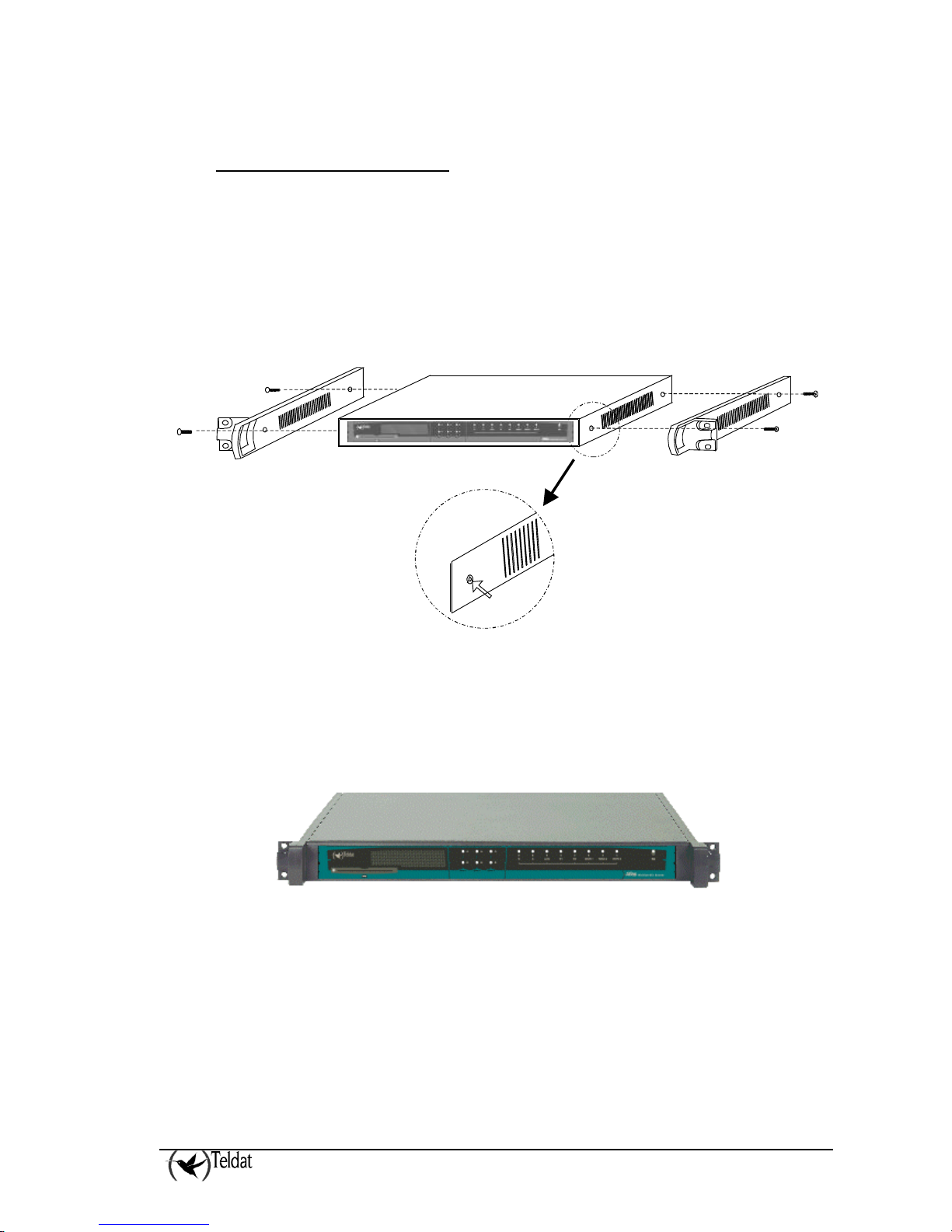
2.3. Installation in a rack
In order to install the Atlas250 router in a 19-inch rack, you require two plastic strips as can be seen in
the figure. The strips and the associated screws are not included in the basic packet and need to be
acquired separately.
Both strips are attached to the device through four screws, two at each side, as shown in the figure.
Figure 7. Attaching the strips
The spaces for the screws in the Atlas250 router leave the factory protected by covers. These can be
removed by using a sharp tool (such as a small flat screwdriver). We recommend removing the upper
cover in order to carry this out more easily.
Figure 8. Device with the strips
Page 10

ATLAS 250 – Installation Manual
8
Doc.DM698-I
Ver.2.0
2.4. Switching on the device
Once the device has been installed in the workplace following the steps previously given, you can
switch on the device. Once this has been carried out, a process of auto-test and initialization,
explained below, takes place.
Firstly, the device carries out a brief auto-test where it checks that the startup program is correct and a
brief detection and initialization of the SDRAM present in the device. With each step taken, a LED
lights up in yellow beginning with the S LED. If any problems are detected the process stops and the
S LED flashes in red. Once this process has completed, the console is available and begins to display
data.
Once the booting process has terminated, an auto-test and auto-detection test of the motherboard
hardware takes place. Firstly all the device LEDs light up in yellow followed by red and lastly in
green. This simplifies the operations visual checking procedure. Subsequently, for each tested
internal element, a device LED lights up in yellow beginning with the S LED. If the test is successful
the LED remains green. If any malfunctions are detected, the corresponding LED remains lit up in red
and once the auto-test has completed, depending on the problem, the device resets and repeats the
process or permits you to operate through the console in order to resolve the problem.
Initializing the device, all the LEDs switch off and the routing application code is decompressed.
During this process the B1 LED flashes in green and the console displays both the dots and the blocks
of the decompressed code.
Once the decompression process has terminated the application executes. The configuration, if found,
is read and the device prompt or an access login is displayed. At this point, if everything has gone
smoothly, the S LED is lit up in green. An example of what is displayed on the console can be found
in section 3.2.a.
Page 11

ATLAS 250 – Installation Manual
9
Doc.DM698-I
Ver.2.0
3. Description of the equipment
The aspect of the equipment can be seen in the following figure. Here you can see both the front panel
and the various rear panels depending on the version.
On the front panel, you can see the LEDs which display the status of the various interfaces and devices
that the Atlas250 router has.
Located on the rear panel is the power point, the AUX console connection (in DB-9 format) for local
configuration and monitoring and the microswitches. From the communications point of view, you
will find the connection to the LAN (in RJ45 format) with the link LED (in yellow), the ISDN
connection (in RJ24 format) with the TERM pushbutton controlling the ISDN bus terminal resistance
and the WAN connectors (in DB-25 format). Finally, depending on the version, you will find diverse
types of slots which permit access to the various expansion cards that can be situated in the interior of
the device; by default, these slots are protected by blind covers and once removed permit you to access
the distinct connectors supporting the expansion cards.
Figure 9. Front and rear panels of the equipment
On the underside of the device you will see a flap that provides access to the serial line drivers. Here
you can select the operating mode (DTE/DCE) and change from one to the other depending on the
standard you are going to use.
DRIVER
DTE/DCE
DRIVER
DTE/DCE
WAN 1WAN 2WAN 3
Figure 10. Location of the drivers access flap
Page 12

ATLAS 250 – Installation Manual
10
Doc.DM698-I
Ver.2.0
3.1. Description of the LEDs
Figure 11. Front panel LED details
ON
Power-on indicator. It lights when connected to the power.
S
DEVICE OPERATION:
OFF: System off.
RED: ERROR: Component operating incorrectly.
YELLOW: The device has a telnet connection activated and is being remotely accessed.
GREEN: System initialized and operating. The device can be accessed via the local console.
X
Not used in the current version.
LAN1-2
OFF: Interface not supported or is not available.
RED: Interface is not available either because it is not enabled or there is a malfunction in the
auto-test.
YELLOW: Interface initialization in process.
GREEN: Interface available. Flashing: Maintenance frame being sent.
ISDN
B1 – B2
OFF: Physical layer not available, either due to cabling problems or to energy saving
procedures.
RED: Temporary, in process of establishing a call.
Permanent, ERROR: errors have been detected in the line or in the call process.
YELLOW: ISDN physical layer is established.
GREEN: Flashing. Call is established.
GREEN-YELLOW: Channel configured in permanent mode, i.e. not switch.
WAN
1 – 2
OFF: Interface not supported or not available.
RED: ERROR: component malfunction.
YELLOW: Interface initialization in process.
GREEN: Flashing. System initialized and operating.
GREEN-YELLOW: Depending on the type of interface. The interface is down and the backup mechanism
is active.
A
OFF: Slot is empty. There is no card.
RED: ERROR: a card has been detected in the slot but operating incorrectly.
YELLOW: Initialization/configuration in process.
GREEN: Card initialized and operating correctly.
S
L
O
T
1 - 3
B
OFF: The card is not executing any operations.
RED: Depending on the type of card.
YELLOW: Depending on the type of card.
GREEN: Depending on the type of card.
Page 13

ATLAS 250 – Installation Manual
11
Doc.DM698-I
Ver.2.0
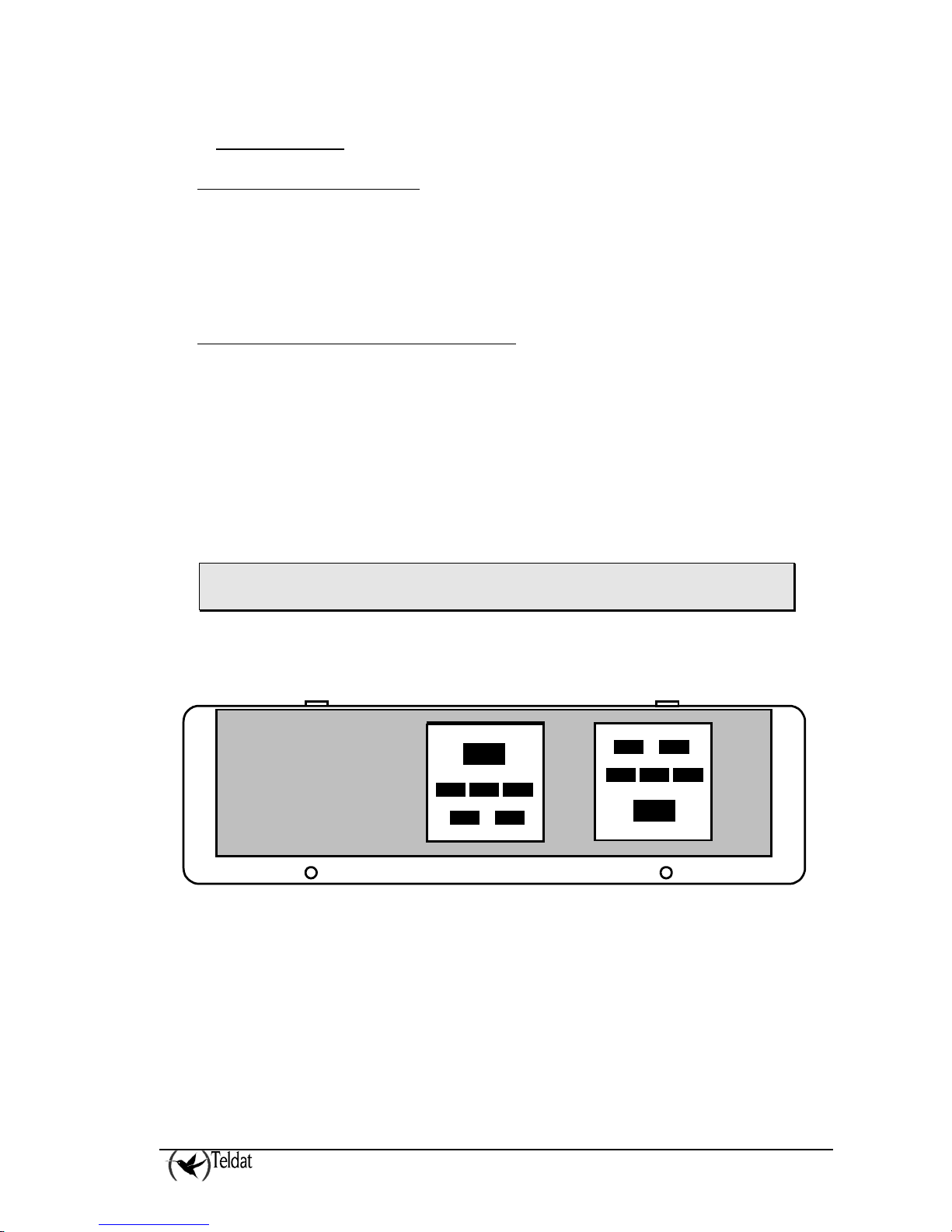
3.2. Description of the microswitches
In the interior of the Atlas250 routers, you will find a group of SW2 microswitches. These are
identified by the numbers ‘1’ to ‘8’ as shown in the below figure. These activate test functions,
software loading functions etc. By default (manufacturer) all these microswitches are in the OFF
position. These should not be handled by the user except in cases to reestablish the default
configuration as described below.
Figure 12. Location of the microswitches
To ensure correct operating procedures, all the microswitches must be in the OFF
position.
a) Procedure to ignore the configuration
This procedure is applied if you have to discard the whole configuration of the device, for example, if
you cannot remember the password.
The procedure is as follows:
• Turn off the device through the ON/OFF switch.
• Using a screwdriver or another sharp instrument, move microswitch ‘5’ to the ON position.
• Turn the device on with the ON/OFF switch.
When the device is switched on, a message similar to the one shown below will appear on the
configuration console:
Page 14

ATLAS 250 – Installation Manual
12
Doc.DM698-I
Ver.2.0
**************************************************
******************* Router Teldat ****************
**************************************************
BOOT CODE VERSION: 01.02 Dec 28 2004 12:56:28
gzip Dec 28 2004 12:56:29
P.C.B.: 72 MASK:0064 Microcode:002D
START FROM FLASH
BIOS CODE DUMP..................
BIOS DATA DUMP...
End of BIOS dump
====================================================================
BIOS TELDAT (c)Teldat
====================================================================
BIOS CODE VERSION: 01.02
CLK=294912 KHz BUSCLK=65536 KHz L0
Date: 02/01/05, Tuesday Time: 11:25:04
SDRAM size: 128 Megabytes
BANK 0: 128 Megabytes (detected)
Caches: ON Write-Back
FLASH: 8 Mb.
NVRAM: 128 Kb.
EEPROM: 2048 Bytes.
DPRAM: 16384 Bytes.
WAN1: DTE
WAN2: DTE
ISAC
RDSI_B
RDSI_B
FAST ETHERNET 1
FAST ETHERNET 2
PCI device: Host bridge
(Bus: 0, Device: 0, Function: 0)
Current production date: 04 44
Current software license: 6 56
Current serial number: 472/00144
BIOS MAC Add: 00-a0-26-70-00-90
>>
........
TRYING APP CODE DUMP
(CONFIGURED) atlas2g.bin ver.: 0.10.5.1 0.0.0.0
.................................................................................
....................................................................................
................................................
....................................................................................
....................
APP DATA DUMP...........................................
Running application
Empty configuration used
Initializing
Press any key to get started
As you can see, the text “Empty configuration used” appears in the box. On reaching this point, you
can set microswitch ‘5’ in the OFF position (it is not necessary to turn off the device), in this way, the
next time you restart the device, the saved configuration is adhered to.
Page 15

ATLAS 250 – Installation Manual
13
Doc.DM698-I
Ver.2.0
4. Appendices
4.1. Smart Card
The configuration is stored in a card in the device and is read each time the device boots. This
configuration is generally stored in the device Flash memory. However, in some models, you can use
an external device in order to store the configuration: a Smart Card, which simplifies the transfer of
configurations from one device to another. The information is compressed in order to take advantage
of the space available in the Smart Card. The choice of the active storing medium where you read the
configuration and where this is stored is carried out through console commands. These commands can
be found in more detail in the “Dm704-I Configuration and Monitoring” manual.
a) Description and insertion
The Smart Card is a card with an integrated circuit permitting you to store and process information.
The available space is variable, however it can always be measured in Kilobytes. The external aspect
of the card is displayed in the following figure: on one side of the card you can see the integrated
circuit and on the other there is an arrow indicating which way to insert the card.
Figure 13. Aspect of a SmartCard
In those models that have this device, the Smart Card is inserted in the slot located on the front panel
of the equipment. The card should be placed in the slot so that the arrow is face up and the chip face
down. The card must be carefully inserted following the arrow until a small click is heard.
Figure 14. SmartCard insertion slot
Next to the insertion slot you can see a LED which indicates the card activity. This LED lights up in
green when it is reading or writing in the card and remains off when there is no activity.
• DO NOT extract or introduce the card when the activity LED is on. Contrariwise
data stored in the card may be lost.
b) Viewing the content
The content of the Smart Card may be viewed from either the console or through FTP.
Page 16

ATLAS 250 – Installation Manual
14
Doc.DM698-I
Ver.2.0
• In order to view the content of the Smart Card, or the free space, use the ‘FILE LIST’
command from the configuration menu (please see manual “Dm704-I Configuration and
Monitoring”). Given that the Smart Card is a slow device, it may take a few seconds to
respond.
*P 4
Config>FILE LIST
Active Device: SmartCard only
A: CODE.BIN 2734052 12/00/08 31:57 Flash
A: ROUTER.CFG 960 03/01/35 03:00 Flash
A: DEF.CFG 816 03/01/25 03:00 Flash
Flash Available Space : 5198 Kbytes
S: PC.CFZ 2983 SmartCard
S: ROUTER.CFZ 543 SmartCard
S: TEST.CFZ 536 SmartCard
SmartCard Available Space : 8040 bytes
Config>
Viewing the Smart Card’s available files on the console
• In order to view the content of the Smart Card accessing the device via FTP, use the ‘dir’
command from the equipment assembled for the Smart Card. The steps are as follows:
• Introduce the login and password.
o If you have defined users, use the names and passwords assigned to these as
login and password.
o If there are no defined users, use “root” as the login.
o If the password has not been configured, press “intro”.
o If you have a console password configured, introduce this password in order to
access the FTP server.
o If authentication with a RADIUS server is activated, introduce the
corresponding password.
• Exit the FTP default device through the “cd ..” command.
• Change to the FTP device using the Smart Card through the “cd smc” command.
• Display the content of the Smart Card through the “dir” command.
C:\atl>ftp 172.24.78.94
Connected to 172.24.78.94.
220 FTP server ready, 1 active clients of 1 simultaneous clients allowed.
User (172.24.78.94:(none)): root
331 User name accepted, need password.
Password:
230 User login complete.
ftp> cd ..
200 CWD root dir successful.
ftp> cd smc
200 CWD Command successful.
ftp> dir
200 PORT is set to IP ADDR = 172.24.51.23 PORT = 1964
150 Data connection open, list transfer in process...
-rwxrwxrwx 1 ftp ftp 415 Jan 16 1999 ROUTER1.CFZ
-rwxrwxrwx 1 ftp ftp 864 Jan 16 1999 ROUTER2.CFZ
-rwxrwxrwx 1 ftp ftp 3551 Jan 16 1999 STARTUP.CFZ
-rwxrwxrwx 1 ftp ftp 543 Jan 16 1999 ROUTER.CFZ
226 List transfer completed, data connection is closed.
591 bytes received in 18,25 seconds (0,03 Kbytes/sec)
ftp> bye
221 Goodbye.
C:\atl>
Viewing the available files in the Smart Card via FTP using a Windows MSDOS
screen
Page 17

ATLAS 250 – Installation Manual
15
Doc.DM698-I
Ver.2.0
c) Write
Configurations can be stored in the Smart Card through FTP and from the console. Writing through
FTP is carried out as described in the “Updating the software and the configurations” appendix of this
manual.
From the console, you can use the ‘SAVE’ and ‘FILE COPY’ configuration process commands. The
‘SAVE’ command always uses the active storing unit. The ‘FILE COPY’ command permits you to
select a unit distinct to the active one (in order to specifically refer to the Smart Card, you need to use
the unit identifier “S:” (s following by a colon). For further information please see manual “Dm704-I
Configuration and Monitoring”.
Choosing the active unit is executed through the ‘CONFIG-MEDIA’ configuration command. This
allows you to select the following options:
• SMARTCARD-FLASH. Both mediums are considered active; priority however is given to
the Smart Card over the Flash memory.
• SMARTCARD. The Smart Card is considered as the only active medium or unit.
• FLASH. The Flash memory is considered as the only active medium or unit.
By default, the device has the value ‘SMARTCARD-FLASH’ configured in those devices that support
Smart Card and the ‘FLASH’ option for those devices which don’t. You can check which unit is
active by using the ‘FILE LIST’ command.
As previously indicated in this appendix, the configuration in the Smart Card is stored in compressed
format. To indicate this, the files stored in the Smart Card have the last letter of the extension
changed to “z”. If the file you wish to store in the Smart Card does not have any extension a “.z” is
added. Any file saved in the Smart Card will be recorded in compressed format through the gzip
compression application.
In cases where the file recorded in the Smart Card is already sent in gzip compressed format, this will
not be compressed nor will the extension be modified. Files transferred via FTP from the Smart Card
to a PC will be transferred in exactly the same way as they were stored in the Smart Card, i.e.
compressed. The compression format used can be decompressed with the majority of decompression
applications available on the market including WinZip. The ‘FILE COPY’ command however, should
the original file be a Smart Card file destined to be a Flash memory file, will copy the file in
decompressed format.
Additionally there are commands to delete (‘FILE DELETE’ command) and to rename (‘FILE
RENAME’ command) files in a storage unit. For further information on these commands please see
manual “Dm704-I Configuration and Monitoring”.
d) Access Mode
Under normal circumstances, the device on booting or on saving the configuration uses the storing
medium which is configured as active.
When the device boots, the behavior, depending on the active medium, is as follows:
Page 18

ATLAS 250 – Installation Manual
16
Doc.DM698-I
Ver.2.0
• SMARTCARD-FLASH. The Smart Card configuration is read. If the card is not present or
the file cannot be found, the operation is repeated in the Flash. If the file is not found in the
Flash memory then the device will boot with the default configuration.
After reading the Smart Card configuration file the device checks to see that this is written in
the Flash memory. If the configuration is not present then the device enters it so that both
mediums are synchronized.
• SMARTCARD. The Smart Card configuration is read. If the card is not present or the file
cannot be found, the device will boot with the default configuration.
• FLASH. The Flash configuration is read. If the file cannot be found the device will boot
with the default configuration.
On saving the configuration through the ‘SAVE’ command, the behavior, depending on the active
media is as follows:
• SMARTCARD-FLASH. The configuration is saved in both the Smart Card and the
Flash. The console indicates the devices where the configuration has been stored and
through a warning text will show the devices where recording has not been possible.
• SMARTCARD. The configuration is saved in the Smart Card.
• FLASH. The configuration is saved in the Flash memory.
Occasionally, you may wish to boot the Smart Card device independently of the active medium
configured in the device and you may want the Smart Card configuration to be automatically stored in
Flash. In this way, in subsequent device start-ups, this will boot with the configuration present in the
Smart Card even if the card has been extracted (this could be useful for example to update the
configuration in a device pool where you need to start from a common base configuration). To do
this, use microswitch ‘5’ (default configuration microswitch) so that provided this is active (ON
position) the following procedure will be executed:
1. Firstly the device will try to read a configuration titled ‘STARTUP.CFZ from the Smart Card.
If this is found, this configuration is copied to the device Flash memory with ROUTER.CFG
as name (configuration file device default name) and is marked as the active configuration file.
If the device has a ROUTER.CFG configuration in the Flash memory, this is stored as
ROUTER.BAK. This is configured as “FLASH” independently of the configured active
medium.
2. If this cannot be found, the device will search the Smart Card for a configuration with the
default name of the configuration file (ROUTER.CFZ). If this is found it is marked as active
and NOT copied to the Flash memory. This is configured as “SMARTCARD-FLASH”
independently of the configured active medium.
3. In cases where neither of the above mentioned files is found, the device will search the Smart
Card for any configuration file (files with extension .cfz). If one is found, the device will boot
with this configuration marking it as the active configuration file. In the same way as the
above case, the configuration will NOT be copied in the Flash memory. This is configured as
“SMARTCARD-FLASH” independently of the configured active medium.
4. Finally, if the Smart Card is not available or none of the configuration files is found, then the
device will boot with the default configuration. The configured active medium is not
modified.
Page 19

ATLAS 250 – Installation Manual
17
Doc.DM698-I
Ver.2.0
e) Format
As with any logical support, the Smart Card must be formatted before it can be used. The Smart
Card is already formatted on leaving the factory. However should it be necessary the Atlas250 has
the means to do this.
In order to format a Smart Card you can use the ‘FILE FORMAT SMARTCARD’ command from the
configuration menu. Please bear in mind that the formatting process destroys any information that is
in the Smart Card, consequently should you format a card containing valid information it will not be
possible to recover this.
You can also format a Smart Card from the BIOS management menus which are accessible on booting
the device: within the disk menu you will find the “format” command which permits you to format the
card.
For further information on how to format your card, please contact you regular supplier or an
authorized technical service.
Page 20

ATLAS 250 – Installation Manual
18
Doc.DM698-I
Ver.2.0
4.2. Troubleshooting
Below, you will find a table, which will help you to solve problems during the installation of the
device. If you cannot resolve the problem, please consult your distributor for additional information.
Symptom Solution
None of the LEDs lights up on the
device
Check the power supply to the device (power source, ON/OFF
switch, main power outlet).
The S LED does not light up. Check that all the microswitches are in the OFF position.
The local console does not
respond.
Check that you are using the correct console cable and that this
is connected to the device and the asynchronous terminal.
Check that the terminal has the correct port configured.
Check that the terminal configuration is 9600 8N1.
Check that the console is not in an events process.
Check that the device is not being remotely accessed via telnet.
The local console is only
displaying garbage
Check that the terminal has the correct port configured.
Check that the terminal configuration is 9600 8N1.
The device does not initialize and
the console displays the WARMUP text.
Check that microswitch ‘1’ is in the OFF position. In this
situation, you may have to reload the device BIOS and the
routing application.
The device is very slow in
displaying the application prompt.
Check that microswitch ‘3’ is in the OFF position.
You have forgotten the password
to access the device
Ignore the configuration through microswitch ‘5’ as explained in
the section on microswitches.
The LAN LED never lights up in
green.
Check that the rear LINK LED is ON.
Check the Ethernet cable and the connection to the network (you
may need a crossover cable).
The WAN LED never lights up in
green.
Check that the cable you are using is adequate, that the driver is
inserted in the correct position (DTE or DCE).
Check that the configuration is correct (speed, protocol, etc.).
The ISDN LEDs never light up in
either yellow or green.
Check that the connection to the bus is correct and that the Sbus
terminal switch is in the correct position.
The LEDS indicate the interfaces
are established but there is no
connectivity at the data levels.
Check the configuration (routes, IP addresses, serial interface
speed, etc).
Page 21

ATLAS 250 – Installation Manual
19
Doc.DM698-I
Ver.2.0
4.3. Updating the software and the configurations
Both the BIOS as well as the routing application code and the configurations are stored in the device
flash memory. This is handled as a standard disk unit. The executable codes have a .bin extension
and can by updated via FTP using the Atlas250 router FTP server, and by XModem through the
device local console.
The configurations have a .cfg extension and can only be read and written via FTP. If you wish to
make copies of your configurations, simply obtain the .cfg router file possessed by the router. In the
same way, if you wish to use a configuration, simply overwrite the said file.
UPDATING THE APPLICATION
The code storage system simulates a standard disk drive unit: you must make sure that
the application file name loaded in the device coincides with that already existing. If
this is not so, it is possible that the loaded code will not automatically activate and the
system will continue to execute the code that existed prior to the updating.
If you always use the same file name, the system will delete the previous code,
substitute it with the new code and activate automatically.
a) Updating using FTP
The Teldat devices have an internal FTP server that is capable is distinguishing if a file that is loading
is from BIOS, application or from another. Therefore, the server operation is completely transparent.
By default, the FTP server is located in port 21; through the configuration, you can
change the FTP port server. You must check to make sure you are accessing the
correct port, if not you will not be able to receive a response from the server.
In order to carry out a code transfer (assuming the server port has not been modified):
• Introduce the login and the password.
o If users have been defined, use the names and passwords for these as login and
password. Updating will be executed or not depending on the user access
levels.
o If there are no defined users, use “root” as login.
o If the password has not been configured, press “intro”.
o If you have the console password configured, introduce the same password in
order to access the FTP server.
o If you have authentication activated with a RADIUS server, introduce the
corresponding password.
• Pass to binary mode through the “binary” command.
• Carry out the transfer through the “put” command.
• Permanently save the loaded file with “quote site savebuffer” command.
• If you want the device to automatically restart and begin executing the new code, you
can send the “quote site reload on” command; on leaving the FTP session,
the device will restart after approximately 30 seconds.
Page 22

ATLAS 250 – Installation Manual
20
Doc.DM698-I
Ver.2.0
C:\atl>ftp 172.24.78.94
Connected to 172.24.78.94.
220 FTP server ready, 1 active clients of 1 simultaneous clients allowed.
User (172.24.78.94:(none)): root
331 User name accepted, need password.
Password:
230 User login complete.
ftp> dir
200 PORT is set to IP ADDR = 172.24.51.23 PORT = 1964
150 Data connection open, list transfer in process...
-rwxrwxrwx 1 ftp ftp 2163872 Nov 27 2001 ATLAS2G.BIN
-rwxrwxrwx 1 ftp ftp 4727 Nov 27 2001 ROUTER.CFG
226 List transfer completed, data connection is closed.
395 bytes received in 0,16 seconds (2,47 Kbytes/sec)
ftp> binary
200 TYPE is set to IMAGE.
ftp> hash
Hash mark printing On (2048 bytes/hash mark).
ftp> put atlas2g.bin
200 PORT is set to IP ADDR = 172.24.51.23 PORT = 1965
150 Data connection open, file transfer in process...
################################################################################
################################################################################
################################################################################
################################################################################
################################################################################
################################################################################
##################################################
226 STOR completed, 2167348 bytes processed, data connection is closed.
2167348 bytes sent in 2,72 seconds (795,65 Kbytes/sec)
ftp> quote site statbuffer
211 Buffer status: MAX-REQ-BUSY 3145728-2179072-2167348 filename: "ATLAS2G.BIN"
ftp> quote site savebuffer
200 SAVEBUFFER completed O.K.
ftp> quote site reload on
200 RELOAD mode is set to ON.
ftp> bye
221 Goodbye.
C:\atl>
Loading the code via FTP using a Windows MSDOS screen
If you need help, you have the standard FTP “help” command available. This permits you to obtain a
commands list (not all of them are operative in this server). “help” <command_name> provides help
on the indicated command. For further information, please consult the Teldat Router manual related
to FTP, reference “Dm724-I FTP Protocol”.
You can, at any point, view the status of the buffer through the “quote site statbuffer” command. If
you wish to delete it, use the “quote site clearbuffer” command.
b) Updating via XModem
This code updating mode is for those cases where you do not have an IP connection available with the
device or for emergencies.
To carry out updating:
• Set the microswitch ‘3’ in the ON position and switch on the device. By default, the
transfer speed is 115200 bps; if you wish to change the said speed you must access the
device console and set a new speed (you are shown how to do this in the following
figure).
• Wait until the B1 LED is green and the S LED is slowly flashing in yellow: the device
is waiting to load the code.
• Through a program with a function to send data with the XModem protocol, you carry
out loading from an application file; you will notice that the S LED is flashing rapidly,
indicating the transfer process. If the S LED passes to red, the transfer has failed; repeat
the process slowing down the speed.
• Once the transfer has successfully completed, you will see that the B1 LED activates in
green and the S LED continues flashing in yellow, indicating that the recording process
is in progress: if the S LED passes to red the recording process has failed; if this passes
to green the recording process has finalized satisfactorily.
Page 23

ATLAS 250 – Installation Manual
21
Doc.DM698-I
Ver.2.0
• Once the code has been successfully loaded, deactivate the microswitch ‘3’ so the
device will not pass to the wait mode in order to download the code through the
XModem.
By default, the application loaded through the XModem is saved with the name
“AT2G.BIN”; you can modify the name, following the instructions that appear on the
console when carrying out the download.
Loading through the console can also be carried out by accessing the BIOS menus; in
order to access the said menus you must press CTRL-T when a series of dots appear
after the “>>” symbols.
====================================================================
BIOS TELDAT (c)Teldat
====================================================================
BIOS CODE VERSION: 01.02
CLK=294912 KHz BUSCLK=65536 KHz L0
Date: 02/01/05, Tuesday Time: 11:34:16
SDRAM size: 128 Megabytes
BANK 0: 128 Megabytes (detected)
Caches: ON Write-Back
FLASH: 8 Mb.
NVRAM: 128 Kb.
EEPROM: 2048 Bytes.
DPRAM: 16384 Bytes.
WAN1: DTE
WAN2: DTE
ISAC
RDSI_B
RDSI_B
FAST ETHERNET 1
FAST ETHERNET 2
PCI device: Host bridge
(Bus: 0, Device: 0, Function: 0)
Current production date: 04 44
Current software license: 6 56
Current serial number: 472/00144
Current file name: AT2G.BIN
Press Ctrl+t to change file name
........
Xmodem whith chk transfer. Default baud rate: 115200
Press any key to change the baud rate
...o.
Select the baud rate transfer:
1. 9600 4. 38400
2. 14400 5. 57600
3. 19200 6. 115200
Press 0 to abort load...
4
Set baud rate to 38400 and send the file with Xmodem with chk protocol.
When the transfer finish, reset baud rate to 9600.
Example of changing the transfer speed
Page 24

ATLAS 250 – Installation Manual
22
Doc.DM698-I
Ver.2.0
Figure 15. Code downloading via XModem through Windows Hyperterminal
Page 25

ATLAS 250 – Installation Manual
23
Doc.DM698-I
Ver.2.0
4.4. Connecting the connectors
• Twisted pair connections (RJ45)
RJ45 LAN
RJ45 PIN Ethernet
1
2
3
4
5
6
7
8
Tx+(input)
Tx-(input)
Rx+(output)
--
--
Rx-(output)
--
--
• ISDN Connector
RJ45 ISDN
RJ45 PIN ISDN
1
2
3
4
5
6
7
8
--
--
Tx+ (output)
Rx+(input)
Rx-(input)
Tx-(output)
--
--
• WAN Connector
NOTE: Cables used for multi-purpose Teldat drivers must not be used in these connections. You must
use end-to-end pin-to-pin connector cables.
STANDARD
DB25
Connector
V.24 V.35 X.21
Pin
Signal UIT Signal V.35 Signal DB15
1 Ground 101 Ground A Ground 1
2 TxD 103 TxD (A) P TxD (A) 2
3 RxD 104 RxD (A) R RxD (A) 4
4 RTS 105
RTS C CONT(B) 10
5 CTS 106
CTS D
6 DSR 107
DSR E
7 GND 102
GND B GND 8
8 DCD 109
DCD F
9 ExTxC (B) W
14 TxD (B) S TxD (B) 9
15 TxC 114 TxC (A) Y
IND(A) 5
16 RxD (B) T
RxD (B) 11
17 RxC 115 RxC (A) V
CLK(A) 6
18 TxC (B) AA
IND(B) 12
19 RxC (B) X
CLK(B) 13
20 DTR 108
DTR H
CONT(A) 3
24 ExTxC 113 ExTxC (A) U
Page 26

ATLAS 250 – Installation Manual
24
Doc.DM698-I
Ver.2.0
• AUX port connections
This is used to locally configure and monitor the device. This permits the connection of an
asynchronous terminal at 9.600 bps without parity and with one stop bit (9600 8N1). This is a female
DB9 connector that behaves as DCE, permitting pin-to-pin connection with a PC asynchronous port or
terminal.
Pin Signal
3
2
5
7-8
1-4-6
TXD
RXD
GND
Joined pins
Joined pins
Page 27

ATLAS 250 – Installation Manual
25
Doc.DM698-I
Ver.2.0
4.5. Technical Specifications
Hardware Architecture
PROCESSORS Freescale PowerQuicc II, at 300 or 400 MHz, depending on
version
MEMORY 64 128 or 256 SDRAM Mbytes, depending on version
STORAGE UNIT FLASH Memory, 4, 8 or 16 Mbytes depending on version
EEPROM 2 Kbytes, NVRAM 128 Kbytes
LAN Interfaces
PROTOCOLS Ethernet (802.3) / Ethernet blue book
Nº PORTS 2
SPEED 10 Mbps (10BaseT)/ 100 Mbps (100BaseT)
CONNECTOR RJ45 female
WAN Interfaces
PROTOCOLS FRAME RELAY, X.25, PPP, SDLC, X.28
INTERFACES Insertable Drivers V.24 / V.35 / X.21 DTE/ DCE
Nº PORTS 2
SPEED 200 to 2048 Kbps
CONNECTOR DB-25 Female
ISDN Interface
ACCESO Basic 2B+D
SPEED 2 x 64 Kbps (B channels)
CONNECTOR RJ45 Female
Configuration Interface
LOCAL TERMINAL V.24 9.600-8-N-1- without flow control
CONNECTOR DB-9 female
AC* Power supply
INPUT VOLTAGE 100 – 240 V ~
INPUT CURRENT 1-0.5 A
INPUT FREQUENCY 47-63 Hz
DC* Power supply
INPUT VOLTAGE -48 V
INPUT CURRENT 1 A
Dimensions and weight
TYPE Desktop
LENGTH x WIDTH x HEIGHT 310 x 415 x 43 mm
WEIGHT 3,5Kg
Environmental Specifications
AMBIENT TEMPERATURE ON: 5º to 55ºC OFF: -20º to 60ºC
RELATIVE HUMIDITY ON: 8% to 85% OFF: 5% to 90%
* Available depending on version
Page 28

ATLAS 250 – Installation Manual
26
Doc.DM698-I
Ver.2.0
4.6. Installing PMC Cards
The Atlas250 features and interfaces can be amplified by inserting PMC boards (PCI mezzanine card).
The Atlas250 will admit up to 3 cards simultaneously. In order to correctly insert the card, please
follow the steps given below. Should you encounter any problems please consult your usual supplier.
1. Switch off the device as described in section 2.1 of this manual.
2. Remove the device from the workplace and place it in a stable, safe place where it can be
easily accessed and handled.
3. Open up the device. To do this you need to remove the upper cover which is secured through
two screws located on the rear panel of the device. A star screwdriver will be needed for this.
Keep the screws in a safe place for subsequent use.
Once the screws have been removed, in order to remove the cover, slide it some 10 mm
towards the rear panel and then remove it by lifting, carefully separating it from the sides.
Place it in a safe place.
Page 29

ATLAS 250 – Installation Manual
27
Doc.DM698-I
Ver.2.0
4. Find the place where the PMC board needs to be located, depending on the availability of the
free slots and the mechanical characteristics of the PMC board. The following figure shows
the Atlas250 baseboard as seen from the device front panel. The various slots are labeled as
SLOT1, SLOT2 and SLOT3.
Each slot possesses a set of elevated connectors with gold contacts and a pair of securing
screws.
5. Remove the blind cover from the selected slot. This cover is located on the rear panel and
secured through three screws. A flat screwdriver is need for this.
Conectores PMC
Identificador
del slot
Tornillos
de
sujeción
Page 30

ATLAS 250 – Installation Manual
28
Doc.DM698-I
Ver.2.0
6. In its place, secure the mold that comes with the board which permits the board to sit bet ter in
the device rear panel. Use the screws mentioned in the above point to secure this.
7. Place PMC board posts over the screws. Secure these firmly.
Page 31

ATLAS 250 – Installation Manual
29
Doc.DM698-I
Ver.2.0
8. Place the PMC card in the slot so that this firstly adjusts to the space on the device rear panel
and subsequently to the two PMC connections. This operation must be carefully carried out
without forcing any piece or part of the device. Check that the board is clearly settled over the
PMC connectors.
9. Screw the PMC board to the posts. For this use two screws with their corresponding washers.
Firmly tighten the screws without damaging the board.
Page 32

ATLAS 250 – Installation Manual
30
Doc.DM698-I
Ver.2.0
10. Close the device using the cover taken off in section 3. To do this, place the cover on top of
the device, without completely closing it, some 10 mm from the front panel. Check that the
cover is sitting properly. Finally slide the cover along in order to close up the device checking
that the sides adjust below the front panel. Secure the cover using the screws from point 3.
11. Connect and switch on the device as explained in section 2.1. Check that the device starts up
as described in section 2.4. Should you detect any problems, switch off the device and make
sure that the above steps have been carried out correctly. If the problem persists, please
contact your usual supplier.
12. Connect a terminal to the console and check that the device detects the PMC board. This
information is displayed on booting as shown in the following figure.
====================================================================
BIOS TELDAT (c)Teldat
====================================================================
BIOS CODE VERSION: 01.02
CLK=294912 KHz BUSCLK=65536 KHz L0
Date: 02/01/05, Tuesday Time: 11:42:47
SDRAM size: 128 Megabytes
BANK 0: 128 Megabytes (detected)
Caches: ON Write-Back
FLASH: 8 Mb.
NVRAM: 128 Kb.
EEPROM: 2048 Bytes.
DPRAM: 16384 Bytes.
WAN1: DTE
WAN2: DTE
ISAC
RDSI_B
RDSI_B
FAST ETHERNET 1
FAST ETHERNET 2
PCI device: Host bridge
(Bus: 0, Device: 0, Function: 0)
PCI device: Ethernet controller
(Bus: 0, Device: 29, Function: 0)
Current production date: 04 44
Current software license: 6 56
Current serial number: 472/00144
BIOS MAC Add: 00-a0-26-70-00-90
13. Finally, in order to use and configure the board, you need to boot the device with a default
configuration.
PMC Board detected
 Loading...