

Page 1

ATLAS X60
Installation Manual
Doc. Dm695-I Ver. 1.0
January, 2008
Page 2

Index
I - Chapter. Installing the Router............................................................... I-1
I - 1. Introduction.................................................................................I-1
I - 1.1. Device description ..........................................................I-1
I - 1.2. Recycling and the Environment......................................I-2
I - 2. Connections.................................................................................I-3
I - 2.1. Power Source Connection...............................................I-3
I - 2.2. Connections ....................................................................I-4
I - 2.2.1. Interfaces GigaEthernet......................................I-4
I - 2.2.2. Connecting the antenna ......................................I-5
I - 2.2.3. Connecting for configuration..............................I-6
I - 3. Meaning of the LEDs..................................................................I-7
I - 3.1. ATLAS 160 and 260.......................................................I-7
I - 3.2. ATLAS 360 ....................................................................I-8
I - 4. Programming the microswitches...............................................I-10
I - 4.1.1. Procedure to ignore the configuration ..............I-10
I - 5. PMC-PCI Cards.........................................................................I-12
I - 5.1. Procedure to install PMC cards.....................................I-12
I - 6. 16 Port SWITCH Board............................................................I-14
II - Chapter. Appendix................................................................................II-16
II - 1. Troubleshooting ...................................................................... II-16
II - 2. Updating the software ............................................................. II-17
II - 3. Connectors............................................................................... II-18
II - 3.1. LAN (GE x) Connector............................................... II-18
II - 3.2. ANT Connectors......................................................... II-18
II - 3.3. Configuration Connector.............................................II-19
II - 4. Technical Specifications.......................................................... II-19
The manufacturer reserves the right to make changes and improvements in
the appropriate features in either software or hardware of this product,
modifying the specifications of this manual without prior notice.
The images presented on the front and back panels of the devices are
provided as an information guideline only. Some small modifications may
exist in the actual device.
i
Page 3

The equipment must be handled by qualified personnel; contrariwise, the
device may be damaged and consequently malfunction.
This device contains elements that are sensitive to electrostatic surges and
shocks, therefore it is essential when handling the equipment that an
antistatic wriststrap is connected to the device chassis and this is placed on
an antistatic mat; and furthermore avoiding any kind of contact between the
device components and necklaces, bracelets, rings, ties etc.
ii
Page 4
I - Chapter.
Installing the Router
I - 1. Introduction
The ATLAS X60 routers are modular devices incorporating encryption
hardware and designed with network convergence in mind as it supports IP
Telephony and the possibility to encode video.
Teldat proposes the
ATLAS X60 for wireless technology, both for the local
network, with wireless access point functionality, as well as for the wide area
network as this device supports the following interface cards: GSM, GPRS,
EDGE, UMTS, HSDPA, CDMA2000, EV-DO and WiMAX.
The
ATLAS X60 executes the “Teldat Internetworking Code” (CIT) which runs
in all the Teldat switch-router families. This is characterized by the enormous
variety of supported functionalities and specially aimed at satisfying access needs
to corporate data networks. The capacity of the Teldat Internetworking Code for
remotely managing devices, the possibility of implementing Quality of Service
mechanisms (QoS), security mechanisms and the ability to create Virtual Private
Networks through IPSec or L2TP, together with the wide range of protocols and
IP routing and bridging functionalities make this an outstanding feature.
The
ATLAS X60 router family can be expanded with up to 4 PCI cards which
allow you to increase the number of interfaces in the device.
This manual will show you how to install and connect these devices.
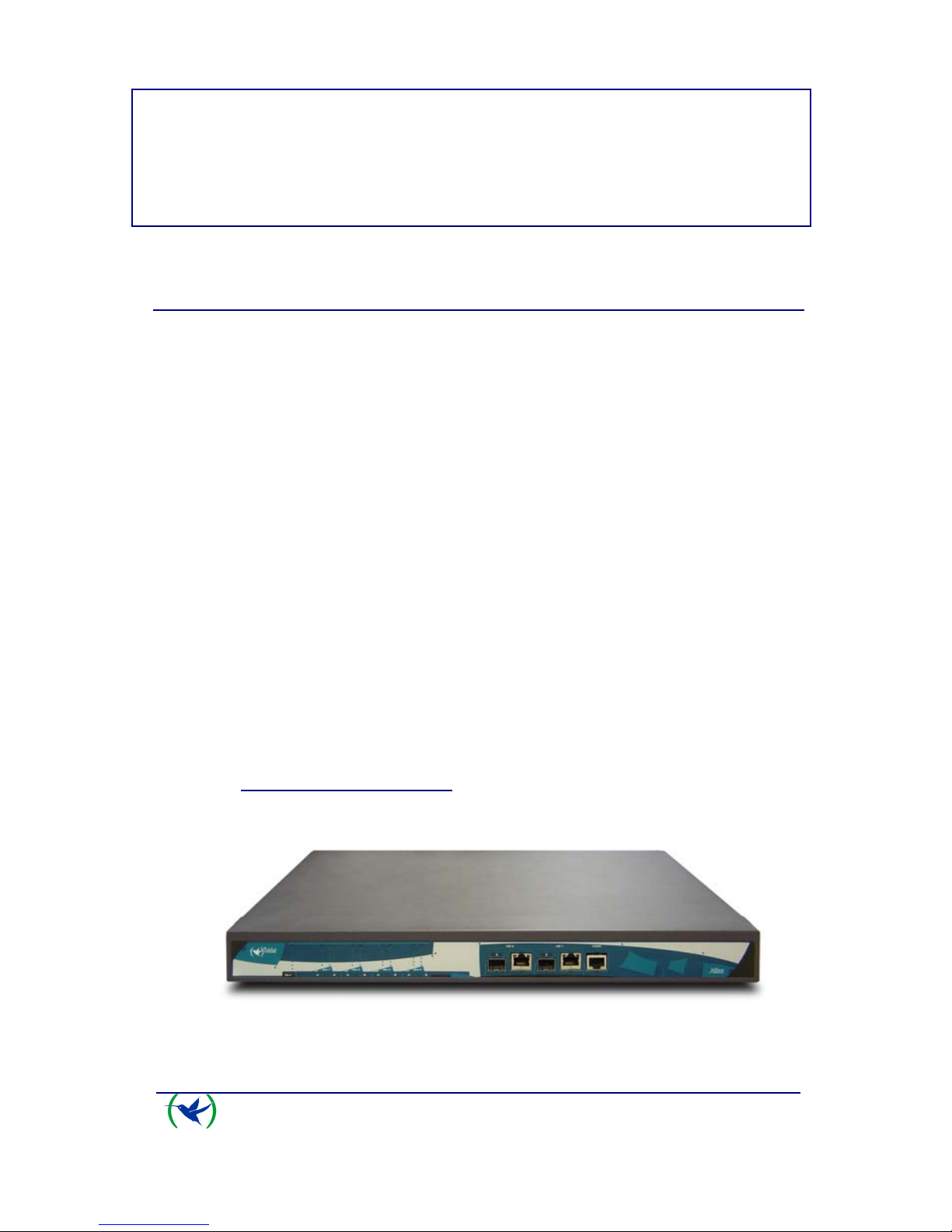
I - 1.1. Device description
ATLAS 160 and 260 Router
ATLAS X60
Installation
I-1
Doc. Dm695-I
Rev. 1.0
Page 5
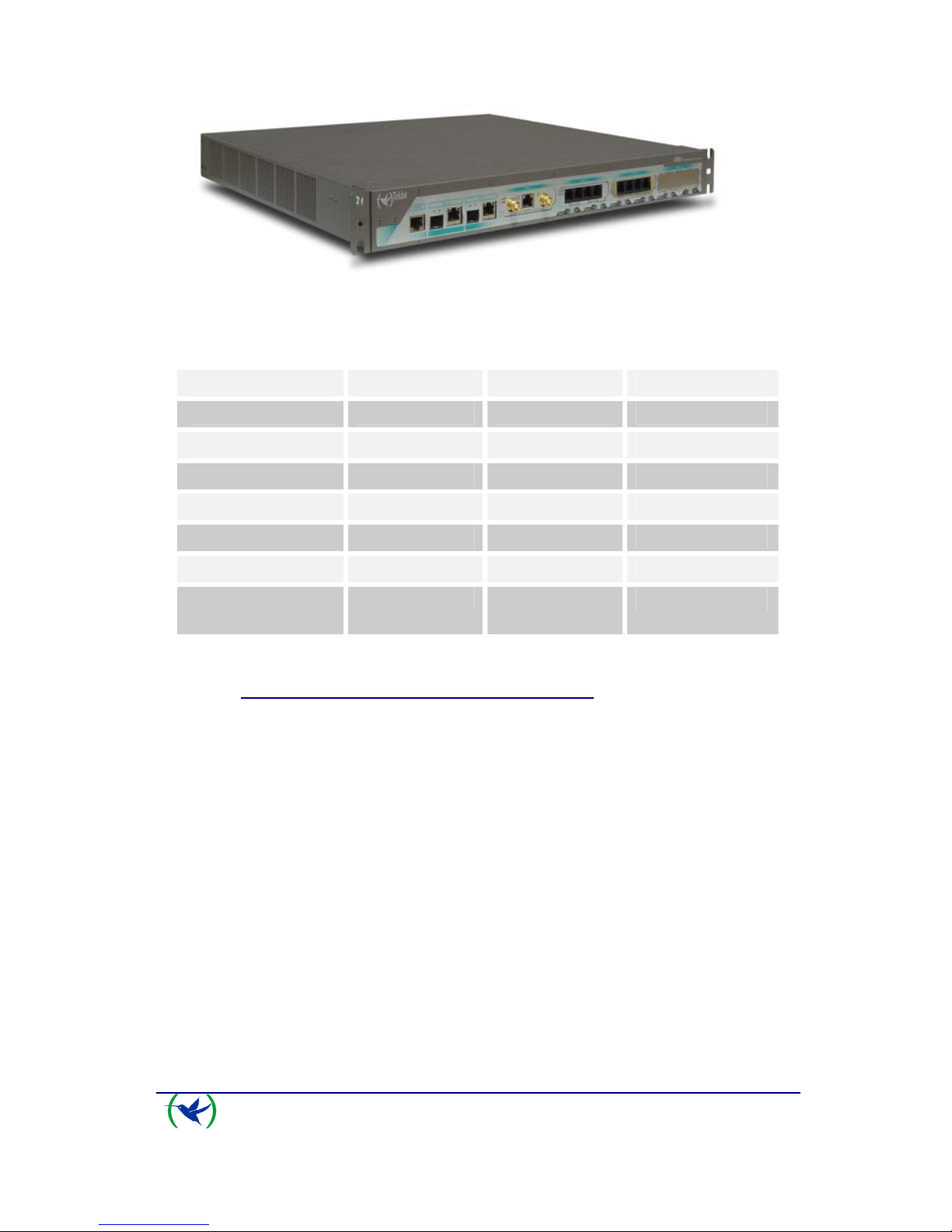
ATLAS 360 Router
ATLAS 160 ATLAS 260 ATLAS 360
FLASH 16M 16M 64M
RAM 128M 128M 256M
PCI SLOTS 2 3 4
MINIPCI 1 1 1
LAN 2 GE 2 GE 2 GE
SWITCH NO NO 16 (optional)
HW
ENCRYPTION
YES YES YES
I - 1.2. Recycling and the Environment
Please do not under any circumstances throw away any ATLAS X60 with
normal domestic waste. Ask your local town hall for information on how to
correctly dispose of them so protecting the environment against e-waste. Always
respect the current laws regarding waste material. Anyone found violating the
environmental laws will be subject to fines and any additional steps established by
law.
All the packing materials i.e. the cardboard box, plastic and any other packaging
together with the pieces making up an
ATLAS X60 must be recycled
complying with the current active laws regarding recycling materials.
The below symbol with a cross over the rubbish container can be seen on the
device. This means that when a device reaches the end of its life, it must be taken
to the official recycling/disposal centers where it must be disposed of in an
environmentally responsible manner and separately from normal domestic waste.
ATLAS X60
Installation
I-2
Doc. Dm695-I
Rev. 1.0
Page 6

I - 2. Connections
BEFORE CONNECTING THE ROUTER PLEASE READ THE
FOLLOWING INSTRUCTIONS CAREFULLY
Workplace Conditions. Main Characteristics
• Excessive cold and heat should be avoided, as should humidity and dust.
• Direct exposure to sunlight should be avoided as well as other heat sources.
The device should not be placed amongst papers, magazines or other elements
that could hinder natural air circulation.
• The device should not be placed very close to strong electromagnetic fields
such as speakers, engines, etc.
• Knocks and/or strong vibrations should be avoided during transport, operation
and storage.
WARNING: Electric supply current for telephone and communication cables is
dangerous. To prevent electric shock while installing, moving or opening the
device covers, cables should be disconnected and connected as follows:
To Connect To Disconnect
Make sure that the device’s power supply switch
is in the OFF position
Turn the switch OFF
Connect all data cables Disconnect the power supply from the device
Connect the power supply to the device Disconnect the data cables
Turn the power supply switch to the ON position
I - 2.1. Power Source Connection
The ATLAS X60 router is powered with an internal power source.
ATLAS X60
Installation
I-3
Doc. Dm695-I
Rev. 1.0
Page 7
To avoid electric shocks, residual current circulation and other unwanted effects,
also affecting communications, the following is recommended:
• It is highly recommended that all interconnected communication
devices are plugged to THE SAME GROUNDED POWER
OUTLET, which should at the same time be of good quality (lower
than 10ohms).
• Whether the workplace is provided with an uninterrupted power
supply system (UPS), regulated supply or it is independent from the
rest (such as lighting, etc.); it is highly recommended that all data
devices should be connected to the same power source. This will
avoid operating and premature aging problems of drivers and other
components.
Connecting the ATLAS 160 and 260 power supply
Connecting the ATLAS 360 power supply
To connect the power source to the device, follow the steps listed in the earlier
table: ensure that the switch is OFF (0) and the power supply is NOT connected
to the main electricity supply; find the POWER plug, located on the rear panel of
the device and insert the power cable. Please use the grounded cable supplied
with the device for this purpose.
I - 2.2. Connections
The ATLAS X60 router has the following connectors available. Some of these
connectors may not be available depending on the model
:
I - 2.2.1. Interfaces GigaEthernet
GE 0, GE 1:
GigaEthernet Interfaces. The
ATLAS X60 router has two connectors to
connect to Ethernet networks. Each interface has two connectors: one optic
connector (1000 LX SFP-LC) and one metal one (10/100/1000 Base-T).
The second LAN (GE 1) requires a software license in order to operate it.
ATLAS X60
Installation
I-4
Doc. Dm695-I
Rev. 1.0
Page 8

Giga Ethernet ATLAS 160 and 260 connectors
Giga Ethernet ATLAS 360 connectors
I - 2.2.2. Connecting the antenna
ANT.:
The
ATLAS X60 router has two connectors to connect to an external antenna
which improves the quality of the signal received and transmitted by the Wireless
LAN module. This module is optional and it’s possible that your device does not
have either a Wireless LAN or the antennas. To assemble and dismantle the
antennas, simply screw them into the connectors labeled ANT. These are located
on the rear of the device.
So that the Wireless LAN interface is operative, the device must have a plug-in
Wireless LAN card and the corresponding software license. Depending on the
model, the antennas are installed in the device at the factory. If your device does
not have the Wireless LAN module incorporated, you can obtain this later on.
The manual accompanying this module will indicate how to install it and the
corresponding antenna cables in the device.
Antenna connector for the Wireless LAN ATLAS 160 and 260
Antenna connector for the Wireless LAN ATLAS 360
ATLAS X60
Installation
I-5
Doc. Dm695-I
Rev. 1.0
Page 9

I - 2.2.3. Connecting for configuration
The ATLAS X60 router has a RJ45 female connector on the front panel
referred to as “
CONF.” which provides access to the device local console. In
order to configure this, you must connect the “
CONF.” port to an asynchronous
terminal (or to a PC with terminal emulation).
Configuration for the terminal must be:
- Speed: 9600 bps
- Eight data bits
- One stop bit
- No parity bit
- No type of flow control
Connection to the configuration port can be carried out using the RJ45 connectors
cable, provided with the device, together with the RJ45 Female-DB9 Female
adaptor also provided with the device.
Adaptador
RJ45H-DB9H
Connecting for configuration
The CONF connector for the ATLAS 160 and 260
ATLAS X60
Installation
I-6
Doc. Dm695-I
Rev. 1.0
Page 10

The CONF connector for the ATLAS 360
I - 3. Meaning of the LEDs
I - 3.1. ATLAS 160 and 260
ATLAS 160 and 260 LEDs
ON Power-on indicator. It lights up when connected to the power supply.
SLOT [1-3]
A & B
Depends on the card installed in the PCI Slot. Normally this is:
OFF: Interface not available or not installed (not supported).
RED: Interface not established, without data connection.
YELLOW: Connecting.
GREEN: Communications established.
SLOT 4
A & B
The device has a MINI-PCI slot where you can install a Wireless LAN daughter card.
Please see the manual on Wireless LAN interfaces to check how the LEDs operate.
Specific connector LEDs
GEX
Optic connector:
-Left: link and activity detection
OFF: There is no link.
RED: Link detected. Flashing depends on the activity.
ATLAS X60
Installation
I-7
Doc. Dm695-I
Rev. 1.0
Page 11

-Right: SFP present
OFF: SFP not present.
RED: SFP present.
Metallic connector:
-Left:
ORANGE: 10Mbps. Flashing depends on the activity.
GREEN: 100Mbps. Flashing depends on the activity.
-Right:
YELLOW: 1000Mbps. Flashing depends on the activity.
OFF: Both off means the link has not been detected.
I - 3.2. ATLAS 360
ATLAS 360 LEDs
ON Power-on indicator. It lights up when connected to the power supply.
S
Router operation
OFF: System stopped.
STEADY: System initialized and operating.
SLOT [1-4]
A & B
Depends on the card installed in the PCI Slot. Normally this is:
OFF: Interface not available or not installed (not supported).
RAPID FLASHING: Interface not established, without data connection.
SLOW FLASHING: Connecting.
STEADY: Communications established.
SLOT 5
A & B
The device has a MINI-PCI slot where you can install a Wireless LAN daughter card.
Please see the manual on Wireless LAN interfaces to check how the LEDs operate.
Specific connector LEDs
ATLAS X60
Installation
I-8
Doc. Dm695-I
Rev. 1.0
Page 12

ATLAS X60
Installation
I-9
Doc. Dm695-I
Rev. 1.0
Optic connector:
-Left: link and activity detection
OFF: There is no link.
RED: Link detected. Flashing depends on the activity.
-Right: SFP present
OFF: SFP not present.
RED: SFP present.
GEX
Metallic connector:
-Left:
ORANGE: 10Mbps. Flashing depends on the activity.
GREEN: 100Mbps. Flashing depends on the activity.
-Right:
YELLOW: 1000Mbps. Flashing depends on the activity.
OFF: Both off means the link has not been detected.
Page 13

ATLAS X60
Installation
I-10
Doc. Dm695-I
Rev. 1.0
I - 4. Programming the microswitches
The ATLAS X60 router has a block of 8 available microswitches which are
used for maintenance and test tasks. To access these you need to carry out the
following steps:
• Switch off the device using the ON/OFF switch.
• Using a screwdriver, open the device.
• Have the device facing you (where the LEDs are located). In this
position, the block of microswitches can be seen in the upper left hand
corner on the motherboard, next to the box ventilators.
In this case, they are only used to load the default configuration. These switches
should not be handled by the user except to establish the default configurations.
So the device operates correctly, all the microswitches must be in the
OFF position.
I - 4.1.1. Procedure to ignore the configuration
This procedure is applied if you have to discard the whole configuration of the
device, for example, if you cannot remember the password.
The procedure is as follows:
• Turn off the device through the ON/OFF switch.
• Open the device.
• Using a screwdriver move microswitch ‘5’ to the ON position.
• Close the device.
• Turn the device on with the ON/OFF switch.
When the device is switched on, a message similar to the one shown below will
appear on the configuration console:
**************************************************
******************* Router Teldat ****************
**************************************************
BIOS CODE DUMP...................
BIOS DATA DUMP....
End of BIOS dump
Boot-stack used: 0x000007A0
Boot-stack free: 0x00001860
====================================================================
BIOS TELDAT (c)Teldat
====================================================================
FLASH BIOS CODE VERSION: 01.04 Nov 26 2007 12:29:48 L0
Current date: Dec 05 2007, Wednesday Current time: 17:42:14
Page 14

ATLAS X60
Installation
I-11
Doc. Dm695-I
Rev. 1.0
System Info:
PCB:0x110 GPPORCR:0x10000003 PVR:0x80210020 SVR:0x80390020
CLKs(KHz): CPU=983040 DDR=196608 LBUS=49152 PCI1=65536 PCI2=32768
Watchdog: Disabled
MMU Mode: Dynamic
ICache: ON; DCache: ON Write-Back; L2Cache: ON
CPU fan speed: 941 rpm
Case fan speed: 941 rpm
Mem Info:
DRAM size: 512 Megabytes
BANK 0: 512 Megabytes (detected)
FLASH: 16 Mb.
NVRAM: 128 Kb.
EEPROM: 2048 Bytes.
Devices:
GIGABIT ETHERNET 1
GIGABIT ETHERNET 2
SECURITY ENGINE
PCI device: PowerPC processor, Host
(Bus: 0, Device: 0, Function: 0)
(Subs. Vendor: 0x0000, Subs. Device: 0x0000)
Slot 1 - PCI device: CardBus bridge
(Bus: 0, Device: 10, Function: 0)
(Subs. Vendor: 0x0000, Subs. Device: 0x0000)
PCI device: PowerPC processor, Host
(Bus: 10, Device: 0, Function: 0)
(Subs. Vendor: 0x0000, Subs. Device: 0x0000)
Current production date: 07 45
Current software license: 18 92
Current serial number: 591/05411
BIOS MAC Add: 00-a0-26-10-95-23
>>
...
......
TRYING APP CODE DUMP
(CONFIGURED) ATLAS3G.BIN ver.: 0.10.7.12 0.0.0.0. .............................
APP DATA DUMP ....................................................................
Bios-stack used: 0x1588
Bios-stack free: 0x2A78
Aux-stack used: 0x13C
Aux-stack free: 0x1EC4
Running application
Default configuration used
Parsing text mode configuration ...
Configuration parsed
Initializing
Press any key to get started
• On reaching this point, you can set microswitch ‘5’ in the OFF position
so that the next time you restart the device, the saved configuration is
adhered to.
• Finally, close the device again.
Page 15

I - 5. PMC-PCI Cards
The ATLAS X60 features and interfaces can be amplified by inserting PMC
boards (PCI mezzanine card). In order to correctly insert the card, please follow
the steps given below.
PMC-PCI SLOT for the ATLAS 160 and 260
PMC-PCI SLOTS for the ATLAS 360
I - 5.1. Procedure to install PMC cards
1. Switch off the device and remove the cables as described in the section on
connection in this manual.
2. Remove the device from the workplace and place it in a stable, safe place
where it can be easily accessed and handled. Open up the device. To do this
you need to remove the upper cover which is secured through two screws
located on the underside of the device.
3. Once the screws have been removed, in order to remove the cover, slide it
towards the back panel and then remove it by lifting it. Place it in a safe
place
4. Find the place where the PMC board needs to be placed. This slot has a set
of raised connectors with gold contacts and a pair of securing screws.
5. Remove the blind cover from the slot. This cover is located either on the
rear panel (ATLAS 160 and 260) or on the front panel (ATLAS 360). Push
this out
6. Place PMC board securing posts over the securing screws. Secure these
firmly.
7. Place the PMC card in the slot so that this firstly adjusts to the space on the
device rear panel and subsequently to the two PMC connectors. This
operation must be carefully carried out without forcing any piece or part of
the device. Check that the board is clearly seated over the PMC connectors
ATLAS X60
Installation
I-12
Doc. Dm695-I
Rev. 1.0
Page 16

ATLAS X60
Installation
I-13
Doc. Dm695-I
Rev. 1.0
8. Screw the PMC board to the posts. For this use two screws with their
corresponding washers. Firmly tighten the screws without damaging the
board.
9. Close the device with the cover. Secure the cover with the screws.
10. Connect and switch on the device as explained in the connection section.
Should you detect any problems, switch off the device and make sure that
the above steps have been carried out correctly. If the problem persists,
please contact your usual supplier.
11. Connect a terminal to the console and check that the device detects the PMC
board.
**************************************************
******************* Router Teldat ****************
**************************************************
BIOS CODE DUMP...................
BIOS DATA DUMP....
End of BIOS dump
Boot-stack used: 0x000007A0
Boot-stack free: 0x00001860
====================================================================
BIOS TELDAT (c)Teldat
====================================================================
FLASH BIOS CODE VERSION: 01.04 Nov 26 2007 12:29:48 L0
Current date: Dec 05 2007, Wednesday Current time: 17:42:14
System Info:
PCB:0x110 GPPORCR:0x10000003 PVR:0x80210020 SVR:0x80390020
CLKs(KHz): CPU=983040 DDR=196608 LBUS=49152 PCI1=65536 PCI2=32768
Watchdog: Disabled
MMU Mode: Dynamic
ICache: ON; DCache: ON Write-Back; L2Cache: ON
CPU fan speed: 941 rpm
Case fan speed: 941 rpm
Mem Info:
DRAM size: 512 Megabytes
BANK 0: 512 Megabytes (detected)
FLASH: 16 Mb.
NVRAM: 128 Kb.
EEPROM: 2048 Bytes.
Devices:
GIGABIT ETHERNET 1
GIGABIT ETHERNET 2
SECURITY ENGINE
PCI device: PowerPC processor, Host
(Bus: 0, Device: 0, Function: 0)
(Subs. Vendor: 0x0000, Subs. Device: 0x0000)
Slot 1 - PCI device: CardBus bridge
(Bus: 0, Device: 10, Function: 0)
(Subs. Vendor: 0x0000, Subs. Device: 0x0000)
PCI device: PowerPC processor, Host
(Bus: 10, Device: 0, Function: 0)
(Subs. Vendor: 0x0000, Subs. Device: 0x0000)
Current production date: 07 45
Current software license: 18 92
Page 17

Current serial number: 591/05411
BIOS MAC Add: 00-a0-26-10-95-23
>>
...
......
TRYING APP CODE DUMP
(CONFIGURED) ATLAS3G.BIN ver.: 0.10.7.12 0.0.0.0. .............................
APP DATA DUMP ....................................................................
Bios-stack used: 0x1588
Bios-stack free: 0x2A78
Aux-stack used: 0x13C
Aux-stack free: 0x1EC4
Running application
Parsing text mode configuration ...
Configuration parsed
Initializing
Press any key to get started
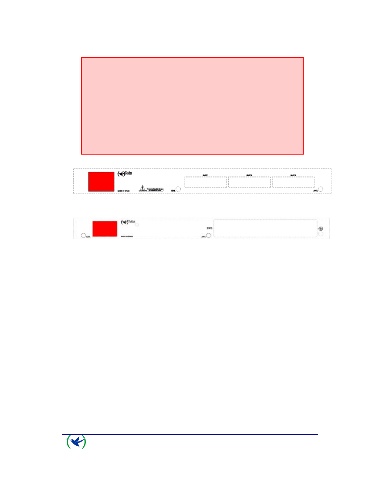
I - 6. 16 Port SWITCH Board
“SWC” SLOT for the ATLAS 360 16 port Switch board
The
ATLAS 360 features and interfaces can be amplified by inserting a 16
port Switch board in the “SWC” slot which can be found on the device rear panel.
In order to correctly insert the board, please follow the steps given below.
1. Switch off the device and remove the data cables as described in the section
on connection in this manual
2. Using a screwdriver, remove the cover over the “SWC” spot. This cover is
located on the rear panel.
3. Should there be a “dummy” board installed, remove it.
4. Insert the 16 port switch board. This operation must be carefully carried out
without forcing any piece or part of the device.
5. Screw down the board. Firmly tighten the screws without damaging the
board.
6. Connect and switch on the device as explained in the connection section.
Should you detect any problems, switch off the device and make sure that
the above steps have been carried out correctly. If the problem persists,
please contact your usual supplier.
7. Connect a terminal to the console and check that the device detects the
Switch board.
ATLAS X60
Installation
I-14
Doc. Dm695-I
Rev. 1.0
Page 18

ATLAS X60
Installation
I-15
Doc. Dm695-I
Rev. 1.0
**************************************************
******************* Router Teldat ****************
**************************************************
BIOS CODE DUMP...................
BIOS DATA DUMP....
End of BIOS dump
Boot-stack used: 0x000007A0
Boot-stack free: 0x00001860
====================================================================
BIOS TELDAT (c)Teldat
====================================================================
FLASH BIOS CODE VERSION: 01.04 Nov 26 2007 12:29:48 L1
Current date: Jan 10 2008, Thursday Current time: 18:09:50
System Info:
PCB:0x083 GPPORCR:0x0BFFFFFF PVR:0x80210020 SVR:0x80390020
CLKs(KHz): CPU=983040 DDR=196608 LBUS=49152 PCI1=65536 PCI2=65536
Watchdog: Disabled
MMU Mode: Dynamic
ICache: ON; DCache: ON Write-Back; L2Cache: ON
Mem Info:
DRAM size: 256 Megabytes
BANK 0: 256 Megabytes (detected)
FLASH: 64 Mb.
NVRAM: 128 Kb.
EEPROM: 2048 Bytes.
Devices:
GIGABIT ETHERNET 1
GIGABIT ETHERNET 2
SWITCH 10/100
SECURITY ENGINE
PCI device: PowerPC processor, Host
(Bus: 0, Device: 0, Function: 0)
(Subs. Vendor: 0x0000, Subs. Device: 0x0000)
PCI device: PowerPC processor, Host
(Bus: 10, Device: 0, Function: 0)
(Subs. Vendor: 0x0000, Subs. Device: 0x0000)
Current production date: 07 16
Current software license: 15 48
Current serial number: 547/00169
BIOS MAC Add: 00-a0-26-80-80-a9
>>
..........
..
TRYING APP CODE DUMP
(CONFIGURED) atlas3g.bin ver.: 0.10.7.12 0.0.0.0
...............................................................................
..................................................................................
.................................................
................................
APP DATA
DUMP........................................................................
Bios-stack used: 0x1588
Bios-stack free: 0x2A78
Aux-stack used: 0x18C
Aux-stack free: 0x1E74
Running application
Flash configuration read
Parsing text mode configuration ...
Configuration parsed
Initializing
Press any key to get started
Page 19

ATLAS X60 - Appendix
II-16
Doc. Dm695-I
Rev. 1.0
II - Chapter.
Appendix
II - 1. Troubleshooting
Below, you will find a table, which will help you to solve problems during the installation
of the device. If you cannot resolve the problem, please consult your distributor for
additional information.
Symptom Solution
None of the LEDs lights up on the
device.
Check the power supply to the device (power
source, ON/OFF switch, main power outlet).
Check that all the microswitches are in the OFF
position.
The local console does not respond. Check that you are using the correct console
cable and that this is connected to the device
and the asynchronous terminal.
Check that the terminal has the correct port
configured.
Check that the terminal configuration is 9600
8N1. Check that the console is not in an events
process. Check that the device is not being
remotely accessed via telnet.
The local console is only displaying
garbage.
Check that the terminal has the correct port
configured.
Check that the terminal configuration is 9600
8N1.
The device does not initialize and the
console displays the WARM-UP text.
Check that microswitch ‘1’ is in the OFF
position. In this situation, you may have to
reload the device BIOS and the routing
application.
The device is very slow in displaying
the application prompt.
Check that microswitch ‘3’ is in the OFF
position.
You have forgotten the password to
access the device.
Ignore the configuration through microswitch
‘5’ as explained in the section on
microswitches.
Page 20

ATLAS X60 Appendix
II-17
Doc. Dm695-I
Rev. 1.0
The LEDS indicate the GE interfaces
are established but there is no
connectivity at the data layer.
Check the configuration (routes, IP addresses,
etc).
II - 2. Updating the software
The ATLAS X60 router can be updated to new releases. Please consult your
distributor for further details on new releases.
The software required to update Teldat routers is supplied in a format known as
distribution. This consists of a single file which contains all the files needed to update
your device as well as in-depth information on the contents of the files.
Page 21

II - 3. Connectors
II - 3.1. LAN (GE x) Connector
RJ45 LAN
RJ45 PIN FE Signals GE Signals
1
2
3
4
5
6
7
8
BI-DA+
BI-DA-
BI-DB+
--
--
BI-DB-
--
--
BI-DA+
BI-DABI-DB+
BI-DC+
BI-DC-
BI-DBBI-DD+
BI-DD-
NOTE:
The Ethernet connectors are equipped with the MDI-X autodetection feature and
autopolarity. Behavior is full-duplex. A null HUB cable is not required to connect to
another Ethernet interface.
II - 3.2. ANT Connectors
PIN ANT
Internal
External
RF in/out
GND
ATLAS X60 Appendix
II-18
Doc. Dm695-I
Rev. 1.0
Page 22

II - 3.3. Configuration Connector
RJ45 CONFIGURATION
RJ45 PIN CONF
1
2
3
4
5
6
7
8
--
RxD
--
GND
--
GND
TxD
--
II - 4. Technical Specifications
Hardware Architecture
PROCESSORS Motorola PowerPC MPC8548
MEMORY 128/640 Mbytes in SDRAM.
STORAGE UNIT FLASH Memory (16/64Mbytes).
EEPROM 2 Kbytes, NVRAM 128 Kbytes.
LAN Interface
PROTOCOLS Ethernet (802.3).
Nº PORTS 2
SPEED 10/100/1000 Mbps (BaseT)
1000 (Base X)
CONNECTOR Dual, RJ45 female. SFP
CABLE STP(Length < 3m)
Optic Fiber
* Depending on the model
Wireless LAN Interface *
STANDARDS Please see the manual on Wireless LAN
SPEED Please see the manual on Wireless LAN
CONNECTOR 2 RF
* Depending on the model
ATLAS X60 Appendix
II-19
Doc. Dm695-I
Rev. 1.0
Page 23

ATLAS X60 Appendix
II-20
Doc. Dm695-I
Rev. 1.0
Configuration Interface
LOCAL TERMINAL V.24 9.600-8-N-1-without flow control.
CONNECTOR RJ45 female, on the rear panel of the device.
ATLAS 360 Power Supply
INPUT VOLTAGE 100-240V AC
INPUT CURRENT 1 A
INPUT FREQUENCY 50-60 Hz
MAXIMUM POWER 100 VA
ATLAS 160 and 260 Power Supply
INPUT VOLTAGE 100-240V AC
INPUT CURRENT 1 A
INPUT FREQUENCY 50-60 Hz
MAXIMUM POWER 100 VA
ATLAS 360 Dimensions and Weight
TYPE Box to be assembled in a 1U high Rack
LENGTH x WIDTH x HEIGHT 483 with rackmount bracket x 395 x 44 mm
444 without rackmount bracket x 395 x 44 mm
WEIGHT 4,0 Kg
ATLAS 160 and 260 Dimensions and Weight
TYPE Box to be assembled in a 1U high Rack
LENGTH x WIDTH x HEIGHT 483 with rackmount bracket x 272 x 44 mm
444 without rackmount bracket x 272 x 44 mm
WEIGHT 3,250 Kg
Environmental Specifications
AMBIENT TEMPERATURE ON: 5º to 45ºC. OFF: -20º to 60ºC.
RELATIVE HUMIDITY ON: 8% to 85%. OFF: 5% to 90%.
 Loading...