

Page 1

ATLAS 150
Installation Manual
Doc. Dm697-I Ver. 1.0
November, 2006
Page 2

Index
I - Chapter. Installing the Router............................................................... I-1
I - 1. Introduction..............................................................................I-1
I - 1.1. Recycling and the Environment...................................I-2
I - 2. Connections..............................................................................I-3
I - 2.1. Power Source Connection............................................I-3
I - 2.2. Data Connection ..........................................................I-4
I - 2.2.1. BRI Connection..................................................... I-6
I - 2.2.2. WAN or external MODEM connection.................I-7
I - 2.2.3. Connecting the antenna..........................................I-7
I - 2.2.4. Connecting for configuration.................................I-7
I - 3. Meaning of the LEDs...............................................................I-9
I - 4. Programming the Microswitches............................................I-10
I - 4.1.1. Procedure to ignore the configuration..................I-10
I - 5. PMC-PCI Cards .....................................................................I-12
I - 5.1. Procedure to install PMC Cards.................................I-12
II - Chapter. Appendices.............................................................................II-14
II - 1. Troubleshooting ...................................................................II-14
II - 2. Updating the Software.......................................................... II-15
II - 3. Connectors ........................................................................... II-16
II - 3.1. LAN Connector (FE x)............................................II-16
II - 3.2. BRI Connector......................................................... II-16
II - 3.3. SERIAL Connector.................................................. II-16
II - 3.4. ANT Connectors...................................................... II-17
II - 3.5. Configuration Connectors........................................ II-18
II - 4. Technical Specifications.......................................................II-19
The manufacturer reserves the right to make changes and improvements in
the appropriate features in either software or hardware of this product,
modifying the specifications of this manual without prior notice.
The images presented on the front and back panels of the devices are
provided as an information guideline only. Some small modifications may
exist in the actual device.
i
Page 3

The equipment must be handled by qualified personnel; contrariwise, the
device may be damaged and consequently malfunction.
This device contains elements that are sensitive to electrostatic surges and
shocks, therefore it is essential when handling the equipment that an
antistatic wriststrap is connected to the device chassis and this is placed on
an antistatic mat; and furthermore avoiding any kind of contact between the
device components and necklaces, bracelets, rings, ties etc.
ii
Page 4
I - Chapter.
Installing the Router
I - 1. Introduction
The ATLAS 150 is a modular device incorporating encryption hardware and
designed with network convergence in mind as it supports IP Telephony and the
possibility to encode video.
Teldat proposes the
ATLAS 150 for wireless technology, both for the local
network, with wireless access point functionality, as well as for the wide area
network as this device supports the following interface cards: GSM, GPRS,
EDGE, UMTS, HSDPA, CDMA2000, EV-DO and WiMAX.
The
ATLAS 150 executes the Teldat CIT (Teldat Internetworking Code -
Código de Internetworking de Teldat), which runs over all the Teldat router
families and is characterized by a wide variety of functionalities they support and
especially orientated to satisfy the access requirements to corporate data networks.
Some of the outstanding features available with CIT are the management capacity,
the possibility to implement Quality of Service mechanisms, security mechanisms
and the possibility to create Virtual Private Networks as well as an extensive
range of protocols and IP routing functionalities.
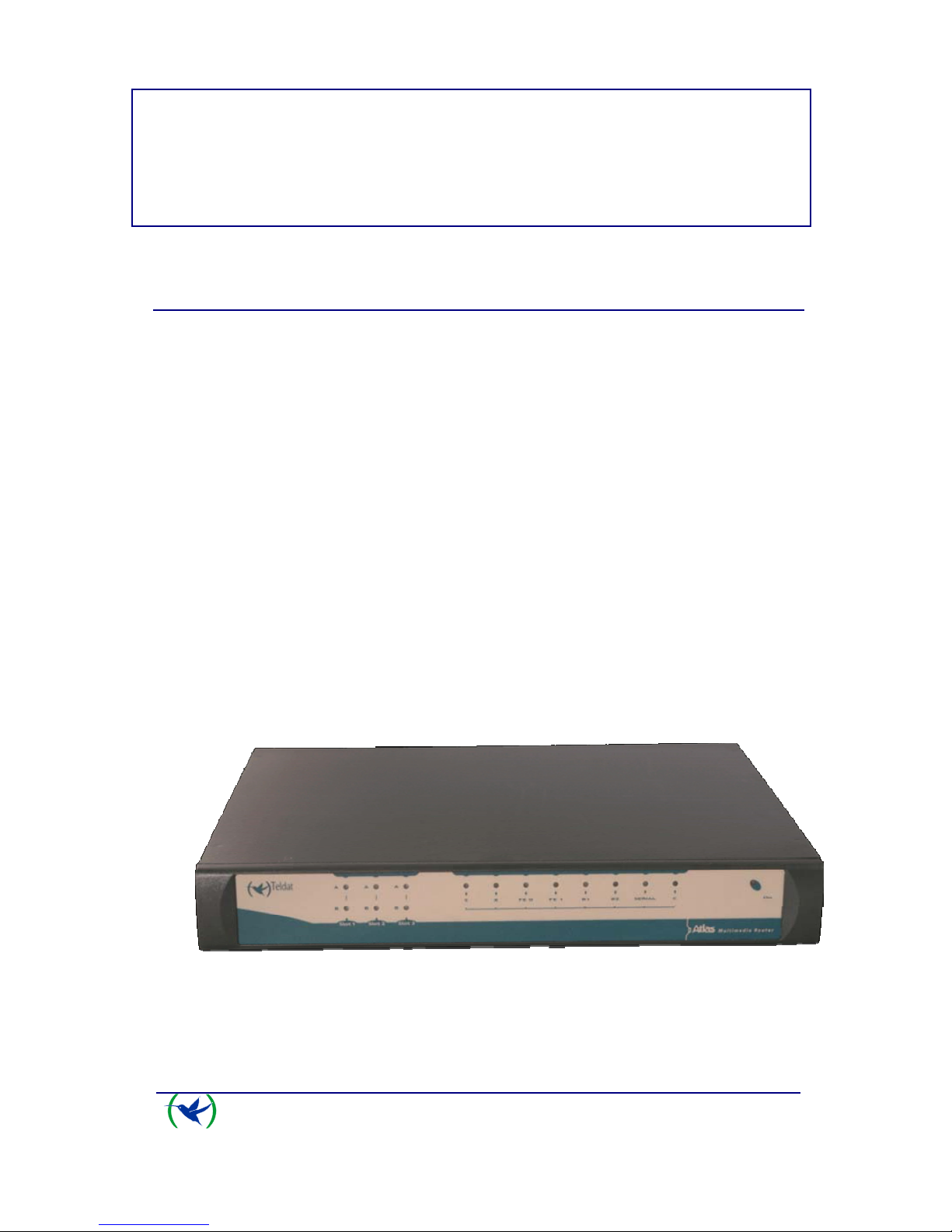
This manual shows you how you need to install and connect this device.
ATLAS 150 front panel
ATLAS 150
Installation
I-1
Doc. Dm697-I
Rev. 1.0
Page 5
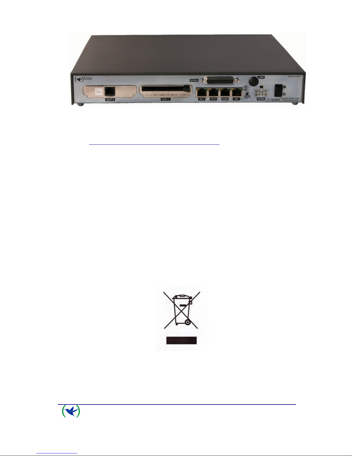
ATLAS 150 rear panel
I - 1.1. Recycling and the Environment
Please do not under any circumstances throw away any ATLAS 150 with
normal domestic waste. Ask your local town hall for information on how to
correctly dispose of them so protecting the environment against e-waste. Always
respect the current laws regarding waste material. Anyone found violating the
environmental laws will be subject to fines and any additional steps established by
law.
All the packing materials i.e. the cardboard box, plastic and any other packaging
together with the pieces making up an
ATLAS 150 must be recycled
complying with the current active laws regarding recycling materials.
The below symbol with a cross over the rubbish container can be seen on the
device. This means that when a device reaches the end of its life, it must be taken
to the official recycling/disposal centers where it must be disposed of in an
environmentally responsible manner and separately from normal domestic waste.
ATLAS 150
Installation
I-2
Doc. Dm697-I
Rev. 1.0
Page 6
ATLAS 150
Installation
I-3
Doc. Dm697-I
Rev. 1.0
I - 2. Connections
BEFORE CONNECTING THE ROUTER PLEASE READ THE
FOLLOWING INSTRUCTIONS CAREFULLY
Workplace Conditions. Main Characteristics
• Areas with excessive humidity and dust should be avoided.
• Direct exposure to sunlight should be avoided as well as other heat sources.
The device should not be placed amongst books, papers, magazines or other
element that could hinder natural air circulation.
• The device should not be placed very close to strong electromagnetic fields
such as speakers, engines, etc.
• Knocks and/or strong vibrations should be avoided during transport, operation
and storage.
WARNING: Electric supply current, telephone and communication cables are
dangerous. To prevent electric shock while installing, moving or opening the
device covers, cables should be disconnected and connected as follows:
To Connect To Disconnect
Ensure that the on/off power supply switch is in
the OFF position
Place the on/off power supply switch in the
OFF position
Check that the power supply is not connected to
either the main electricity supply or the device
Disconne ct the power supply from the main
electricity supply
Connect all data cables Disconne ct the power supply from the device
Connect the power supply to the device Disconne ct the data cables
Connect the power supply to the main electricity
supply
Place the device’s on/off power supply switch in
the ON position
I - 2.1. Power Source Connection
The ATLAS 150 router is powered with an external AC/DC source.
To avoid electric shocks, residual current circulation and other unwanted effects,
also affecting communications, the following is recommended:
Page 7
• It is highly recommended that all interconnected communication
devices are plugged to THE SAME GROUNDED POWER
OUTLET, which should at the same time be of good quality (lower
than 10ohms).
• Whether the workplace is provided with an uninterrupted power
supply system (UPS), regulated supply or it is independent from the
rest (such as lighting, etc.); it is highly recommended that all data
devices should be connected to the same power source. This will
avoid operating and premature aging problems of drivers and other
components.
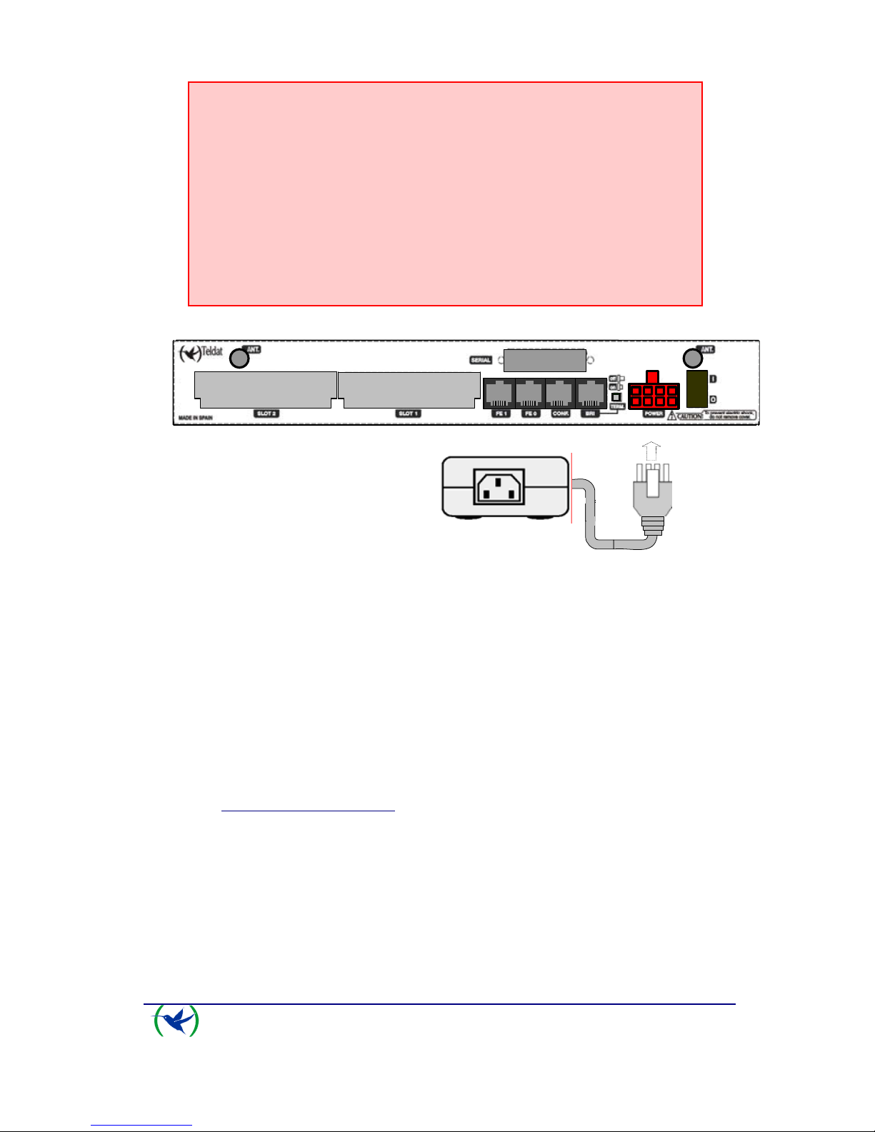
Power supply connection with external source
To connect the power source to the device, follow the steps listed in the earlier
table: ensure that the switch is OFF (0) and the power supply is NOT connected
to the main electricity supply; find the POWER plug, located on the rear panel of
the device and plug it into the power source: both the connector and the receptacle
are designed so it is only possible to insert it in the correct position.
For subsequent connection of the power source to the main electricity supply, use
the grounded cable provided for this purpose.
ATLAS 150
Installation
I-4
Doc. Dm697-I
Rev. 1.0
I - 2.2. Data Connection
The ATLAS 150 router has the following connectors available. Some of these
connectors may not be available depending on the model
:
Page 8

FE 0, FE 1:
The
ATLAS 150 has two female RJ45 connectors in order to connect to the
Ethernet 10BaseT / 100BaseT networks through shielded twisted pairs (STP) or
unshielded (UTP) cables.
Depending on the design of the network, the connection is carried out through a
HUB or directly to another terminal device Ethernet interface through a crossover
cable (please consult your supplier for information on crossover Ethernet cables).
The second LAN (FE 1) requires a software license in order to operate.
BRI:
ISDN 2B-D basic interface; this has an activation mechanism, through 2 jumpers,
for the S bus terminal load.
This requires a software license in order to operate.
SERIAL:
Serial interface in order to connect to a WAN or an external modem.
ANT.:
RF antenna connectors.
So that the Wireless LAN interface is operative, the device must have a plug-in
Wireless LAN card and the corresponding software license. Depending on the
model, the antennas are installed in the device at the factory. If your device does
not have the Wireless LAN module incorporated, you can obtain this later on.
The manual accompanying this module will indicate how to install it and the
corresponding antenna cables in the device.
ATLAS 150
Installation
I-5
Doc. Dm697-I
Rev. 1.0
Page 9

I - 2.2.1. BRI Connection
The BRI interface has a 4 wire RJ45 female connector in order to connect to the S
bus coming from the ISDN network terminator (NT1 or TR1).
In order to connect, use the cable with RJ45 male connections provided with the
device.
Passive-Bus terminal resistances
The
ATLAS 150 router has a pushbutton (labeled as “TERM”) in order to
connect the BUS-S termination resistances. The placing of these terminal
resistances in the correct position is important as contrariwise this can lead to
errors in data (or voice), particularly if the “S” bus line is long. On leaving the
factory, the pushbutton, by default, is in the “ON” position.
• The only or last terminal on the ISDN “S” bus
The “TERM” pushbutton must be in the ON position if the router is the only
element connected to the network terminal (NT1, TR1, etc) or is in the last
position on the ISDN “S” bus.
hecho por M.A. Berr ojo
Atlas
Teldat
NT1 / TR1
S interface
(4 wires)
ISDN
U interface
(2 wires)
Location as the only or last terminal
• Intermediate position in the ISDN “S” bus
The “TERM” pushbutton must be in the OFF position if the router occupies
an intermediate position in the ISDN “S” bus.
ATLAS 150
Installation
I-6
Doc. Dm697-I
Rev. 1.0
Page 10

hecho por M.A. Berrojo
Atlas
Teldat
NT1 / TR1
S interface
(4 wires)
ISDN
U interface
(2 wires)
Location in an intermediate position in the bus
I - 2.2.2. WAN or external MODEM connection
The DTE/DCE multistandard serial interfaces have a DB25 female connector in
order to connect to an external modem or for connection to X.25, Frame Relay
networks, etc.
Depending on the type of connection established, a different type of cable will be
needed. This cable can be supplied by Teldat if you wish.
On the inside of the device, there is a slot to insert the driver which could be V.24
DTE/DCE, V.35 DTE/DCE and X.21 DTE/DCE. These drivers are not multi-
purpose. The configuration for the operation mode is carried out by inverting the
position of the driver (this appears labeled as “T” indicating that this acts as
terminal, and “M” indicating modem functions). The operation mode is that
indicated by the label closest to the connector.
The default configuration for the drivers (on leaving the factory) is
indicated on a label located on the underside of the device.
I - 2.2.3. Connecting the antenna
The ATLAS 150 router has two connectors to connect an external antenna
which improves the quality of the signal received and transmitted through the
Wireless LAN module. This module is optional; it is possible that your device
does not have Wireless LAN and consequently no antennas. To assemble and
disassemble the antennas, simply screw them into the connectors labeled as ANT
located on the rear of the device.
ATLAS 150
Installation
I-7
Doc. Dm697-I
Rev. 1.0
I - 2.2.4. Connecting for configuration
The ATLAS 150 router has a RJ45 female connector on the rear panel referred
to as “
CONF.” which provides access to the device’s local console. In order to
Page 11

configure this, you must connect the “CONF.” port to an asynchronous terminal
(or to a PC with terminal emulation).
Configuration for the terminal must be:
- Speed: 9600 bps
- Eight data bits
- One stop bit
- No parity bit
- No type of flow control
Connection to the configuration port can be carried out using the RJ45 connectors
cable, provided with the device, together with the RJ45 Female-DB9 Female
adaptor also provided with the device.
Connecting for configuration
ATLAS 150
Installation
I-8
Doc. Dm697-I
Rev. 1.0
Page 12

I - 3. Meaning of the LEDs
Atlas 150 Router Front Panel
ON
Power-on indicator. It lights up when connected to the power.
S
DEVICE OPERATION:
OFF: System off.
RED: ERROR: Component operating incorrectly.
YELLOW: The device has a telnet connection activated and is being remotely accessed.
GREEN: System initialized and operating. The device can be accessed via the local
console.
X
Not used in the current version.
LAN1-2
OFF: Interface not supported or is not available.
RED: Interface is not available either because it is not enabled or there is a malfunction in the auto-
test.
YELLOW: Interface initialization in process.
GREEN: Interface available. Flashing: Maintenance frame being sent.
ISDN
B1 – B2
OFF: Physical layer not available, either due to cabling problems or to energy saving
procedures.
RED: Temporary, in process of establishing a call.
Permanent, ERROR: errors have been detected in the line or in the call process.
YELLOW: ISDN physical layer is established.
GREEN: Flashing. Call is established.
GREEN-YELLOW: Channel configured in permanent mode, i.e. not switched.
SERIAL
OFF: Interface not supported or not available.
RED: ERROR: component malfunction.
AMARILLO: In process of initializing the interface.
VERDE: Flashing. System initialized and operating.
VERDE-AMARILLO: Depending on the type of interface. The interface is down and the backup
mechanism is active.
ATLAS 150
Installation
I-9
Doc. Dm697-I
Rev. 1.0
Page 13

ATLAS 150
Installation
I-10
Doc. Dm697-I
Rev. 1.0
A
OFF: Slot is empty. There is no card.
RED: ERROR: a card has been detected in the slot but operating incorrectly.
YELLOW: Initialization/configuration in process.
GREEN: Card initialized and operating correctly.
S
L
O
T
1 - 2
B
OFF: The card is not executing any operations.
RED: Depending on the type of card.
YELLOW: Depending on the type of card.
GREEN: Depending on the type of card.
SLOT
3
A - B
The device has a MINI-PCI slot where you can install a Wireless LAN daughter card.
Please see the manual on Wireless LAN interfaces to check the meaning of the LEDs’ operations.
I - 4. Programming the Microswitches
The ATLAS 150 router has a block of 8 microswitches available, located on
the underside of the device, which are used for maintenance and test tasks. In
this case, they are only used to load the default configuration.
These switches should not be handled by the user except to establish the default
configurations.
So the device operates correctly, all the microswitches must be in the
OFF position.
I - 4.1.1. Procedure to ignore the configuration
This procedure is applied if you have to discard the whole configuration of the
device, for example, if you cannot remember the password.
The procedure is as follows:
• Turn off the device through the ON/OFF switch.
• Using a screwdriver move microswitch ‘5’ to the ON position.
• Turn the device on with the ON/OFF switch.
When the device is switched on, a message similar to the one shown below will
appear on the configuration console:
Page 14

ATLAS 150
Installation
I-11
Doc. Dm697-I
Rev. 1.0
**************************************************
******************* Router Teldat ****************
**************************************************
BOOT CODE VERSION: 01.06 Jan 2 2006 10:22:22
gzip Dec 28 2005 09:54:11
P.C.B.: A0 MASK:0C10 Microcode:00E1
START FROM FLASH
BIOS CODE DUMP....................
BIOS DATA DUMP...
End of BIOS dump
Boot-stack used: 0x00000C38
Boot-stack free: 0x000013C8
====================================================================
BIOS TELDAT (c)Teldat
====================================================================
BIOS CODE VERSION: 01.06
CLK=262144 KHz BUSCLK=65536 KHz PCICLK=65536 KHz L0
Date: 01/12/06, Thursday Time: 12:40:13
SDRAM size: 32 Megabytes
BANK 0: 32 Megabytes (detected)
Caches: ON Write-Back
FLASH: 64 Mb.
NVRAM: 128 Kb.
EEPROM: 2048 Bytes.
DPRAM: 8192 Bytes.
ISAC
RDSI_B
RDSI_B
SECURITY ENGINE
PCI device: Host bridge
(Bus: 0, Device: 0, Function: 0)
(Subs. Vendor: 0x0000, Subs. Device: 0x0000)
Current production date: 00 00
Current software license: 12 15
Current serial number: 550/05646
BIOS MAC Add: 00-a0-26-a0-16-0e
>>
........
TRYING APP CODE DUMP
(CONFIGURED) ATLAS2G.BIN ver.: 0.10.6.12 0.0.0.0 ............................
................................................................................
................................................................................
................................................................................
................................................................................
.............................
APP DATA DUMP...........................................................
Bios-stack used: 0x1490
Bios-stack free: 0x2B70
Aux-stack used: 0x124
Aux-stack free: 0x1EDC
Running application
Default configuration used
Parsing text mode configuration ...
Configuration parsed
Initializing
Press any key to get started
On reaching this point, you can reset microswitch ‘5’ in the OFF position (it is not
necessary to turn off the device), in this way, the next time you restart the device,
and the saved configuration is adhered to.
Page 15

ATLAS 150
Installation
I-12
Doc. Dm697-I
Rev. 1.0
I - 5. PMC-PCI Cards
The ATLAS 150 features and interfaces can be amplified by inserting PMC
boards (PCI mezzanine card). In order to correctly insert the card, please follow
the steps given below.
I - 5.1. Procedure to install PMC Cards
1. Switch off the device and remove the cables as described in the section on
connection in this manual.
2. Remove the device from the workplace and place it in a stable, safe place
where it can be easily accessed and handled. Open up the device. To do this
you need to remove the upper cover which is secured through four screws
located on the underside of the device.
3. Once the screws have been removed, in order to remove the cover, slide it
towards the front panel and then remove it by lifting it. Place it in a safe
place.
4. Find the place where the PMC board needs to be located. This slot has a set
of elevated connectors with gold contacts and a pair of securing screws.
5. Remove the blind cover from the spot. This cover is located on the rear
panel. Push this out.
6. Place PMC board securing posts over the securing screws. Secure these
firmly.
7. Place the PMC card in the slot so that this firstly adjusts to the space on the
device rear panel and subsequently to the two PMC connections. This
operation must be carefully carried out without forcing any piece or part of
the device. Check that the board is clearly settled over the PMC connectors.
8. Screw the PMC board to the posts. For this use two screws with their
corresponding washers. Firmly tighten the screws without damaging the
board.
9. Close the device with the cover. To do this, place the device upside down
adjusting the three slots on the underside in the device’s front panel and
subsequently adjust the cover. Secure the cover with the screws.
10. Connect and switch on the device as explained in the connection section.
Should you detect any problems, switch off the device and make sure that
the above steps have been carried out correctly. If the problem persists,
please contact your usual supplier.
11. Connect a terminal to the console and check that the device detects the PMC
board.
Page 16

ATLAS 150
Installation
I-13
Doc. Dm697-I
Rev. 1.0
**************************************************
******************* Router Teldat ****************
**************************************************
BOOT CODE VERSION: 01.06 Jan 2 2006 10:22:22
gzip Dec 28 2005 09:54:11
P.C.B.: A0 MASK:0C10 Microcode:00E1
START FROM FLASH
BIOS CODE DUMP....................
BIOS DATA DUMP...
End of BIOS dump
Boot-stack used: 0x00000C38
Boot-stack free: 0x000013C8
====================================================================
BIOS TELDAT (c)Teldat
====================================================================
BIOS CODE VERSION: 01.06
CLK=262144 KHz BUSCLK=65536 KHz PCICLK=65536 KHz L0
Date: 01/12/06, Thursday Time: 12:40:13
SDRAM size: 32 Megabytes
BANK 0: 32 Megabytes (detected)
Caches: ON Write-Back
FLASH: 64 Mb.
NVRAM: 128 Kb.
EEPROM: 2048 Bytes.
DPRAM: 8192 Bytes.
ISAC
RDSI_B
RDSI_B
SECURITY ENGINE
PCI device: Host bridge
(Bus: 0, Device: 0, Function: 0)
(Subs. Vendor: 0x0000, Subs. Device: 0x0000)
Slot 1 - PCI device: CardBus bridge
(Bus: 0, Device: 10, Function: 0)
(Subs. Vendor: 0x0000, Subs. Device: 0x0000)
Current production date: 00 00
Current software license: 12 15
Current serial number: 550/05646
BIOS MAC Add: 00-a0-26-a0-16-0e
Page 17

ATLAS 150 - Appendices
II-14
Doc. Dm697-I
Rev. 1.0
II - Chapter.
Appendices
II - 1. Troubleshooting
Below, you will find a table, which will help you to solve problems during the installation
of the device. If you cannot resolve the problem, please consult your distributor for
additional information.
Symptom Solution
None of the LEDs lights up on the
device.
Check the power supply to the device (power
source, ON/OFF switch, main power outlet).
The S LED does not light up. Check that all the microswitches are in the OFF
position.
The local console does not respond. Check that you are using the correct console
cable and that this is connected to the device
and the asynchronous terminal.
Check that the terminal has the correct port
configured.
Check that the terminal configuration is 9600
8N1. Check that the console is not in an events
process. Check that the device is not being
remotely accessed via telnet.
The local console is only displaying
garbage.
Check that the terminal has the correct port
configured.
Check that the terminal configuration is 9600
8N1
The device does not initialize and the
console displays the WARM-UP text.
Check that microswitch ‘1’ is in the OFF
position. In this situation, you may have to
reload the device BIOS and the routing
application.
The device is very slow in displaying
the application prompt.
Check that microswitch ‘3’ is in the OFF
position.
You have forgotten the password to
access the device.
Ignore the configuration through microswitch
‘5’ as explained in the section on
microswitches.
Page 18

ATLAS 150 Appendices
II-15
Doc. Dm697-I
Rev. 1.0
The LANx LED never lights up in
green.
Check that the rear corresponding LINK LED is
ON; contrariwise check the Ethernet cable and
the connection to the network (you may need a
crossover cable).
The BRI LED never lights up in
either yellow or green.
If your device has an ISDN interface, check that
the connection to the bus is correct and that the
S bus terminal switch is in the correct position.
The LEDS indicate the FE interfaces
are established but there is no
connectivity at the data layer.
Check the configuration (routes, IP addresses,
etc).
II - 2. Updating the Software
The ATLAS 150 router can be updated to new releases. Please consult your distributor
for further details on new releases.
There are various ways you can update a Teldat router: please see the manual on updating
software for further information.
The software required to update Teldat routers is supplied in a format known as
distribution. This consists of a single file which contains all the files needed to update
your device as well as in-depth information on the contents of the files.
Page 19

II - 3. Connectors
II - 3.1. LAN Connector (FE x)
RJ45 LAN
RJ45 PIN LAN
1
2
3
4
5
6
7
8
Tx+(input)
Tx-(input)
Rx+(output)
--
--
Rx-(output)
--
--
II - 3.2. BRI Connector
RJ45 ISDN
RJ45 PIN ISDN
1
2
3
4
5
6
7
8
--
--
Tx+ (output)
Rx+(input)
Rx-(input)
Tx-(output)
--
--
II - 3.3. SERIAL Connector
NOTE: Cables used for multi-purpose Teldat drivers must not be used in this
connector. You must use end-to-end pin-to-pin connector cables
ATLAS 150 Appendices
II-16
Doc. Dm697-I
Rev. 1.0
Page 20

STANDARD
DB25 V.24 V.35 X.21
Pin Signal UIT Signal V.35 Signal DB15
1 Ground 101 Ground A Ground 1
2 TxD 103 TxD (A) P TxD (A) 2
3 RxD 104 RxD (A) R RxD (A) 4
4 RTS 105 RTS C CONT(B) 10
5 CTS 106 CTS D
6 DSR 107 DSR E
7 GND 102 GND B GND 8
8 DCD 109 DCD F
9 ExTxC (B) W
14 TxD (B) S TxD (B) 9
15 TxC 114 TxC (A) Y IND(A) 5
16 RxD (B) T RxD (B) 11
17 RxC 115 RxC (A) V CLK(A) 6
18 TxC (B) AA IND(B) 12
19 RxC (B) X CLK(B) 13
20 DTR 108 DTR H CONT(A) 3
24 ExTxC 113 ExTxC (A) U
II - 3.4. ANT Connectors
PIN ANT
Internal
External
RF in/out
GND
ATLAS 150 Appendices
II-17
Doc. Dm697-I
Rev. 1.0
Page 21

II - 3.5. Configuration Connectors
RJ45 CONFIGURATION
RJ45 PIN CONF
1
2
3
4
5
6
7
8
--
RxD
--
GND
--
GND
TxD
--
ATLAS 150 Appendices
II-18
Doc. Dm697-I
Rev. 1.0
Page 22

ATLAS 150 Appendices
II-19
Doc. Dm697-I
Rev. 1.0
II - 4. Technical Specifications
Hardware Architecture
PROCESSORS Motorola PowerPC MPC8272
MEMORY 128/640 Mbytes in SDRAM.
STORAGE UNIT FLASH Memory (16/64Mbytes).
EEPROM 2 Kbytes, NVRAM 128 Kbytes.
LAN Interface
PROTOCOLS Ethernet (802.3).
Nº OF PORTS 1+1*
SPEED 10/100 Mbps (BaseT)
CONNECTOR RJ45 female.
CABLE STP(Length < 3m)
* Depending on the model
Wireless LAN Interface*
STANDARDS Consult the manual on Wireless LAN
SPEED Consult the manual on Wireless LAN
CONNECTOR 2 RF
* Depending on the model
SERIAL Interface*
PROTOCOLS FRAME RELAY, X.25, PPP, SDLC, X.28, SCADA
INTERFACES Insertable Driver: V.24 / V.35 / X.21 DTE/ DCE
Nº OF PORTS 1
SPEED 300 to 2048 Kbps
CONNECTOR DB-25 Female
* Depending on the model
ISDN Interface*
ACCESS Basic 2B+D.
SPEED 2 x 64 Kbps (B Channels).
CONNECTOR RJ45 female.
CABLE Length < 3m
* Depending on the model
Page 23

ATLAS 150 Appendices
II-20
Doc. Dm697-I
Rev. 1.0
Configuration Interface
LOCAL TERMINAL V.24 9.600-8-N-1- without flow control.
CONNECTOR RJ45 female, on the rear panel of the device.
Power Supply
INPUT VOLTAGE +5V,+12V,-12V DC.
INPUT CURRENT 5 A (a +5V DC), 1 A (a +12V DC) and 0.1 A (a -12V DC).
MAXIMUM POWER 40 W.
External Power Source
INPUT VOLTAGE 100-240V AC
INPUT CURRENT 1 A
INPUT FREQUENCY 50-60 Hz
MAXIMUM POWER 100 VA
Dimensions and Weight
TYPE Desktop.
LENGTH x WIDTH x HEIGHT 309 x 270 x 44 mm
WEIGHT 1,5 Kg
Environmental Specifications
AMBIENT TEMPERATURE ON: 5º to 45ºC. OFF: -20º to 60ºC.
RELATIVE HUMIDITY ON: 8% to 85%. OFF: 5% to 90%.
 Loading...