

Telco Systems ACCESS 241-FXO, ACCESS 241, ACCESS 211N, ACCESS 211 User Manual

ACCESS 241-FXO
ACCESS 241
ACCESS 211
ACCESS 211N
(AC-241-FXO/AC-241/AC-211/AC-211N)
VOIP GATEWAY USER GUIDE
MN100129 Rev E

ACCES S 241-FXO/ 241/ 211 VOIP GATEWAY USER GUIDE
Revision History
Revision Date Description
A01 April 01, 2004 1. Adapted for UL/FCC
2. Section 10.4 formerly for H.323 and SIP i s now
separated – now Section 10.4 for SIP with revised rules
for Hold call, Call waiting, Transfer call, and Conference
(flash without followin g di gits), and Section 1 0.5 for
H.323 with contents as before.
B March 02, 2005 Adapted for Version 4.53.29
C Jul y 2005 Added AC-241 to AC-211 support.
Adapted for Version 4.56
D Sept e mber 20 05 Add ed AC - 241- F X O.
Adapted for AC-241FXO versi on 5.1,
AC-241 and AC-211 version 4.57
E Nov em ber 200 5 Add ed AC - 211N suppor t . This rev is ion of A C- 211N
accommodates s/w version 4.57
Co pyr ight © Te lc o Sy st em s, Lt d. , 2005. A ll r ight s r eserv ed. Al l tr adem ark s ar e pro pe rty of the ir
respective ow ners. No part of this documenta tion may be reproduced in any form or by any means
o r used t o make any der ivat iv e wo rk ( such a s t ran slat io n, tr ans format ion, or adapt ation) wit ho ut
permis s ion from Te lco Syst ems, Ltd.
T he informat ion and spe cification s in t hi s guide are subject t o change without prio r noti ce .
2
MN100129 Rev E

ACCES S 241-FXO/ 241/ 211 VOIP GATEWAY USER GUIDE
T able o f Co nten ts
INTRODUCTION............................................................................................................. 5
TERMINOLOGY................................................................................................................. 5
HOW TO GET HELP............................................................................................................ 5
ACCESS 241-FXO OVERVIEW AND I NS T ALL AT IO N...................................................... 6
OVERVIEW ...................................................................................................................... 6
THE FRONT PANEL............................................................................................................ 6
THE REAR PANEL.............................................................................................................. 7
BEFORE YOU INSTALL ....................................................................................................... 7
Required Equipment List.................................................................................................8
INSTALLING YOUR ACCESS 241-FXO VOIP GATEW A Y ............................................................. 9
ACCESS 241 OVE RVI E W AND I NS T AL L ATIO N..............................................................11
OVERVIEW .....................................................................................................................11
THE FRONT PANEL...........................................................................................................11
THE REAR PANEL.............................................................................................................12
BEFORE YOU INSTALL ......................................................................................................13
Required Equipment List................................................................................................13
INSTALLING YOUR ACCESS 241 VOIP GATEWAY....................................................................14
ACCESS 211 AND ACCES S 211N OVERVIEW AND INST ALLATIO N...............................16
OVERVIEW .....................................................................................................................16
THE FRONT PANEL...........................................................................................................17
Access 211 ..................................................................................................................17
Access 211N ................................................................................................................18
THE REAR PANEL.............................................................................................................19
Access 211 ..................................................................................................................19
Access 211N ................................................................................................................19
BEFORE YOU INSTALL ......................................................................................................20
Required Equipment List................................................................................................20
INSTALLING YOUR ACCESS 211/ACCESS 211N VOIP GATEWAY WITH A SINGLE PC.......................21
INSTA LLING YOUR ACCESS 211/ACCESS 211N VOIP GATEWAY WITH A HOME NETWORK ..............23
WALL-MOUNTING THE GATEWAY UNIT.....................................................................25
USING THE GATEWAY..................................................................................................26
FIRST CALL....................................................................................................................26
PST N PORT CALLING WITH ACCESS 241-FXO.......................................................................26
PSTN Outgoing Calls....................................................................................................26
PSTN Incoming Calls....................................................................................................26
PSTN Call Behavior during Unit Power-down or Inactive VoIP Service (Voice LED is off).........26
LIFE LINE PORT CA LLING WIT H ACCESS 241 AND ACCE SS 211 ..................................................26
Life-line Port Calls during Unit Power-down or Inactive VoIP Service (Voice LED is off)..........26
ADVANCED CALLING FEATURES FOR SIP..............................................................................26
Ca ll Wai tin g................................................................................................................27
Caller ID Display, Caller Identity on Call W aiting..............................................................27
Conference Call ...........................................................................................................27
Call Forwarding...........................................................................................................27
Condit ional Call Forwarding..........................................................................................27
Attended Transfer Call...................................................................................................27
Blind Transfer Call .......................................................................................................27
Hold...........................................................................................................................27
Do Not Disturb (DND) ..................................................................................................28
3
MN100129 Rev E

ACCES S 241-FXO/ 241/ 211 VOIP GATEWAY USER GUIDE
Red i a l ing o f La s t Recei ved Cal l .......................................................................................28
Bl o ck Las t Recei ved Call er.............................................................................................28
Auto Redial..................................................................................................................28
Block Caller ID ............................................................................................................28
Anonymous Cal l Rejection..............................................................................................28
ADVANCED CALLING FEATURES FOR H.323...........................................................................28
Ca ll Wai tin g................................................................................................................28
Conference Call ...........................................................................................................29
Call Forwarding...........................................................................................................29
Transferring a Call .......................................................................................................29
Hold...........................................................................................................................29
ADVANCED CALLING FEATURES FOR MGCP .........................................................................29
ADVANCED CO NFI G URAT I O N VIA T H E W EB..............................................................30
WAN CONFIGURATION.....................................................................................................30
ENABLING POINT-TO-POINT PROTOCOL OVER ETHERN ET (PPPOE).............................................33
ENABLING POINT-TO-POINT T PROTOCOL (PPTP)...................................................................34
MAC SPOOFING ..............................................................................................................34
LAN CONFIGURATION......................................................................................................35
Configuring LAN Settings...............................................................................................36
DHCP Server Configuration...........................................................................................37
Port Forwarding..........................................................................................................39
Enabling the Network Address Translator (NAT)................................................................40
SECURI TY CONFIGURATION................................................................................................42
LINE CONFIGURATION ......................................................................................................43
Call Forward Line Configuration....................................................................................43
Gain Control Configuration (Volume) ..............................................................................43
COMPLETING THE GATEWAY CONFIGURATION.......................................................................46
TROUBLESHOOTING....................................................................................................47
SPECIFICATIONS..........................................................................................................48
4
MN100129 Rev E

ACCES S 241-FXO/ 241/ 211 VOIP GATEWAY USER GUIDE
Introdu ctio n
Thank you f or purchas ing this pr oduc t. W e a t Tel c o S ys te ms a re confide n t th a t y ou w ill ob tain full
satisfaction from your new VoIP gateway. Pl ease read this guide carefully i n order to ma ke use of
all the advanced feat ures provided by this product.
Th is guide is intended for users connecting to th e Internet or Intranet with VoIP service set up by a
VoIP provider and the Acce ss 241-FXO/Acce s s 241/Ac ces s 211/ Acce s s 211N Gateway fa ctory
pre-co nfigu red . If this is no t th e c ase , refe r to the ad mi nistra to r's manual.
Terminology
T hrougho ut this guide, t he Acc ess 241 -FXO, Acce ss 241 , Access 211 an d A ccess 211N will be
ref erred to as “the Gateway”, excluding cases when referring specif ically to the Access 241-FXO,
the Access 241, Access 211 or Access 211N.
How to Ge t Help
For technical support, pleas e contact the local distribu tor that su pplied the u ni t.
5
MN100129 Rev E
ACCES S 241-FXO/ 241/ 211 VOIP GATEWAY USER GUIDE
Access 241 -FX O Ov ervi ew a nd I nsta lla tion
Overview
T he A cc es s 241 -FX O (A C- 241-F XO) i s a t erm in a l Voice-o ver- IP ( VoIP) W A N gatewa y devic e
an d t elephon e a dapto r. T he A cce ss 24 1- FXO h as t wo in depen dent phone po rt s (FXS) an d on e
PSTN port ( FXO) . The FXS phon e ports e nable yo u to connect one or two independent analo g
telephone or Fax lines and communicate over the Internet Intranet. The PSTN (FXO) port is used to
connect to the Publ ic Switc hed T elephone Network. (PSTN ). T he combination of both F XS and
FX O po rts e nabl es us in g yo ur t eleph one t o co mm unic at e ov er th e i nternet , int ran et and p ubli c
telephone netw ork.
The Access 241-FXO has 1 WAN and 4 LAN ports; all a re 10/100Mbps Ethernet ports. The WAN
port connects to your modem and the LAN ports c onnect to up to 4 PCs .
T he Access 241-FXO s upports all stan dard analog DTM F tele phone s and acce s so ri es, including:
• Single-line touch-tone t elephones.
• Multiple-li ne touch- tone tel ephones.
• T ouch -t one te lephone s with redial or speed-dial feature s .
• P hones or accessor ies that support Caller ID.
• Answering machines with touch-tone support.
• P hones or accessor ies that support Dist inctive Ring.
NOTE Pul se-dial te lephones and ac cessories are not supported.
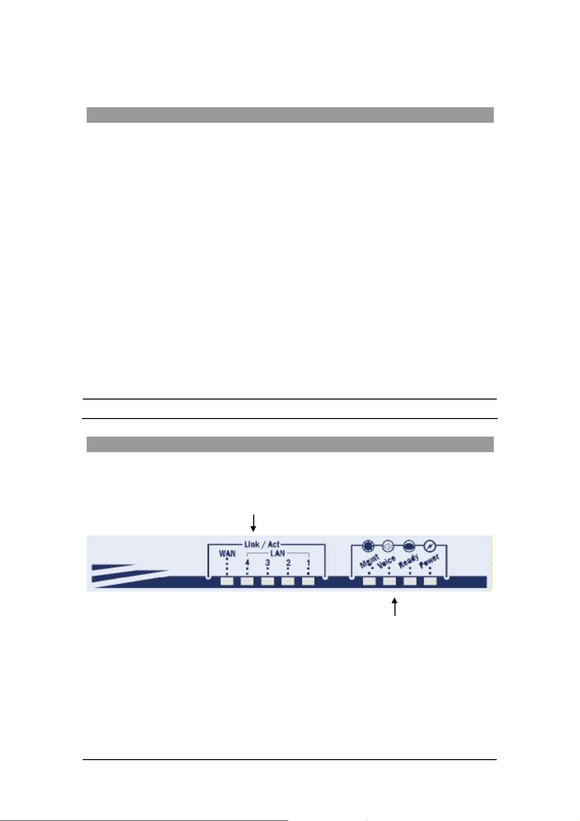
T he Front Pa nel
The Access 241-FXO Gateway’s front panel contains nine LEDs:
• Five link LEDs indicate Link and Activity st atus for the WAN and LAN ports. St eady
glow indicat e s Link, and blinking indicate s Activity.
Four s tatus LEDs provide operati ng information e xplai ned in the followi ng t abl e.
6
MN100129 Rev E
ACCES S 241-FXO/ 241/ 211/ 211N VOIP GATEWAY USER GUIDE
Sta t u s LED Indic at o r s
LED Mod e H .323 , MGC P, SIP St at u s Do wnlo ader St at us
Power
Ready
Voice
Mngt
LAN
(1,2,3,4 )
WAN
Steady glow Power OK Power OK
Blinking Application OK Loader OK
Steady glow Gateway registered with Gatekeeper
/ Call Agen t / SIP Server
Blinking Management activity Management activity
Steady Glow
Bli nking
Steady Glow
Bli nking
Link is up
LAN Activity
Link is up
WAN Acti vity
Link is up
LAN Activity
Link is up
WAN Acti vity
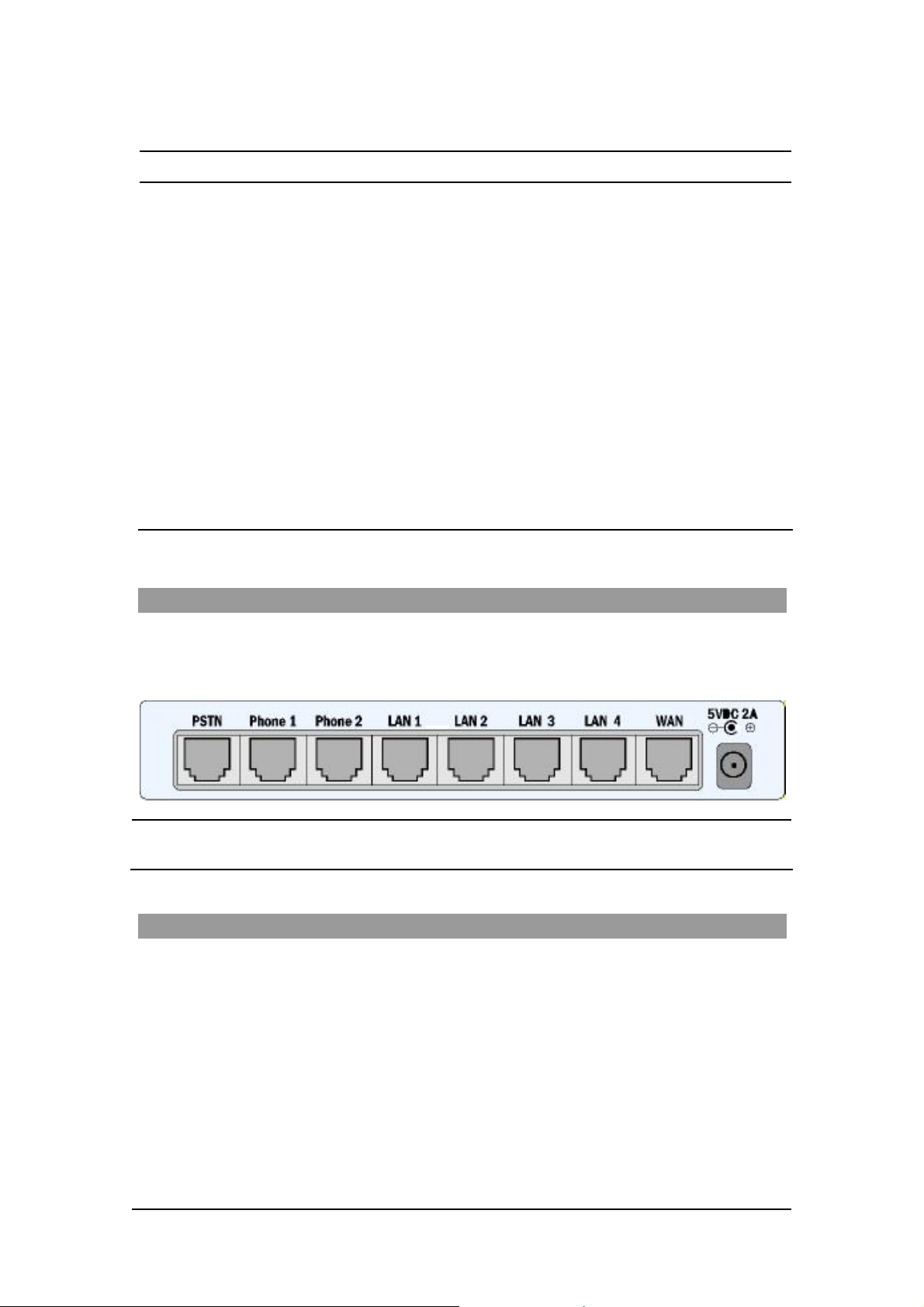
The Rear Panel
T he r ea r panel contain s the phone connecto rs, one W AN, four L AN connecto rs and t he input D C
po wer connector , as sho wn in the follo wing f igur e. The PSTN socket on the left is designed to
provide a public telephone network connec tion.
CAUTION Never connect the Phone1 and P hone2 connectors to the public tele phone
outlet, or to e ac h othe r .
Before You Install
Be fore you begin t o in stall your Ac ce s s 241 VoIP Ga t eway, m ake sure that the temp erature and
humidi ty of the opera ting envir onme n t ar e ke p t w ithi n the foll owing lim i ts:
Ambie nt temperature: 0°C - 45°C (32°F - 113°C)
Humidi ty: 10% - 90% non-condensi ng
7
MN100129 Rev E

ACCES S 241-FXO/ 241/ 211/ 211N VOIP GATEWAY USER GUIDE
Required Equipment List
• Optionally, up to four PC s or l aptop c omput e rs wit h LAN card, we b browser and
Telnet.
• One 10/100 BaseTX ( RJ-45) Eth ernet cable (sup plied) for the Ethernet connection
fro m the Ac ces s 2 41 G atew ay to you r route r or mod e m.
• Add i tional 10/100Bas eTX (RJ -4 5) E the r ne t ca b l es (n ot s u ppl ie d ) t o co nn ect the
Gateway to the computers.
• Two push-button te le phon es with DTMF (tone signal) capa bility (not supplie d).
• An AC/5VDC power adapt er (sup plied).
The Access 241 Gateway must be powered by an external UL listed limited
power source or Class I I power source (AC/DC ada pter), rated input: 100 240 V, 47-63Hz, 0.5A, output: 5VDC @ 2.6A.
The phone ports (P hone1 and Phone2) a re intende d for i ndoor connections
only and must not be connec te d to the publ ic tel ephone network.
ONLY the PSTN port can be connected to the public tel ephone network
outlet.
8
MN100129 Rev E

ACCES S 241-FXO/ 241/ 211/ 211N VOIP GATEWAY USER GUIDE
Installing your Access 241-FXO VoIP Gateway
1. Unpack the Gateway unit.
2. Verify you have the components listed in the Required Equipme nt
3. Place the Gat eway on a desktop or other level surface, or mo unt it on a wall. Choose a
loc a tio n tha t is nea r the devi ces t o be co n ne c ted and close to a n elec trical outl e t. If you w an t
to mount the unit on the wall , refe r to De tails fo r Wa ll Mounti ng th e G a tew a y Uni t
4. Connect the W AN port on the Gateway’s rear panel to the Ethernet socket on your
br oadband modem using an Ethernet ca ble.
5. Connect a LAN port on the Gatew ay’s rea r panel to the network socket on your PC using an
E th er n e t cable.
6. Connect addi tional PCs to the other LAN ports as described in the previ ous s tep.
7. Us e Phone cables to conne ct the telephones to the Ph one1 and P hone2 ports on t he rear of
the G ateway. (If your provider enables only one phone li ne, connect the phone to the Phone1
port)
li st above.
.
It is possible to connect u p to fi ve phones in pa rall el to each phone port. To d o so, conne ct a
5 -way sp litter to th e phone po rt. (If y o ur prov i der en able s o nl y one ph one l ine, use th e
Phon e 1 po rt on t he G a te way).
8 Conn ec t the Phone cab l e fro m the PSTN wall socke t to the G a tew ay’s PSTN port.
9
MN100129 Rev E

ACCES S 241-FXO/ 241/ 211/ 211N VOIP GATEWAY USER GUIDE
9. V erify that al l s ys tem components are properl y ins talled. Make sure that all cable connectors
are securely positioned in t he appropriate ports .
1 0. Co nnect th e po we r a dapter to t he Gat eway’ s po we r conn ect o r on t he re ar of th e un it .
Conn ect the p o wer adapt er to a wall sock et .
11. Check that the Power LED on the Gat eway’s front panel glow steadily.
12 . Tur n on the PC s . F or e ach PC pe r f orm t he followi ng :
12a. If you are using a DSL modem, you will need to enable PPPoE on the Gateway and disable
PPPoE on the PC. To e nab l e PPPoE on the G a tew a y:
1) Open the web browser and put the IP of the Gateway in the address field (the
fact ory default IP address of the LAN interface is 192.168.100.1).
2) I n th e vertical menu bar on the left of t he Gate wa y Web page, s elect WAN.
The WAN Status page a ppears.
3) In th e horizont al menu bar of t he WAN page, select PPPoE. The W AN PPPoE
Configuration page appears.
4) Select Yes in the Enable PPP oE dr op-do wn li s t box.
5) Fill in the username and password in t he Authentication fields as supplied by your
DSL p rovider. Optio nally you can enter th e service nam e for the requested service.
To select a specific provider, enter his access name in the AC n ame field.
6) Click Save PPPo E Settings.
7) After entering and saving all configurations, you must reset the Gateway. In t he
vertical menu b ar of the curren t pag e, s elec t Reset. The Reset page appears.
8) Select Power on rese t and click t he Reset button. Th e Gateway power cycles and
the application’s home page opens with the new configuration settings.
For more information see section “Enabling P oint-to-Point Protocol over Ethernet
(PPPoE)”.
12 b. If you ar e usin g a cable modem, note th at some cable modems need to be powered off an d
then on after being connected t o th e Gate way . For such modems you can also power off the
Gatewa y and then power on for fas ter connec tion.
13 . Wait f or the Voice LED on the Gateway front panel to glow, indicating connection to your
I nternet an d Vo IP prov i der s. It m ay t ake a m in ut e or t wo for t h ese conn ect ion s t o be
established.
14. Verify that your broadband Internet s ervice functions properl y.
15. Pick up the phone on each li ne to verify that you c an hear the dial tone .
On ce the in stallation is complete , y ou can use your Gateway for telephone calls and for the Internet,
as s uming t hat you h ave a con nec ti o n suppli ed by y our V oI P pro vi d er.
If any problems are experie nced during the ins tall ation of the uni t, please contact you r l oc al vend or.
10
MN100129 Rev E
ACCES S 241-FXO/ 241/ 211/ 211N VOIP GATEWAY USER GUIDE
Access 241 O verv iew and Inst all atio n
Overview
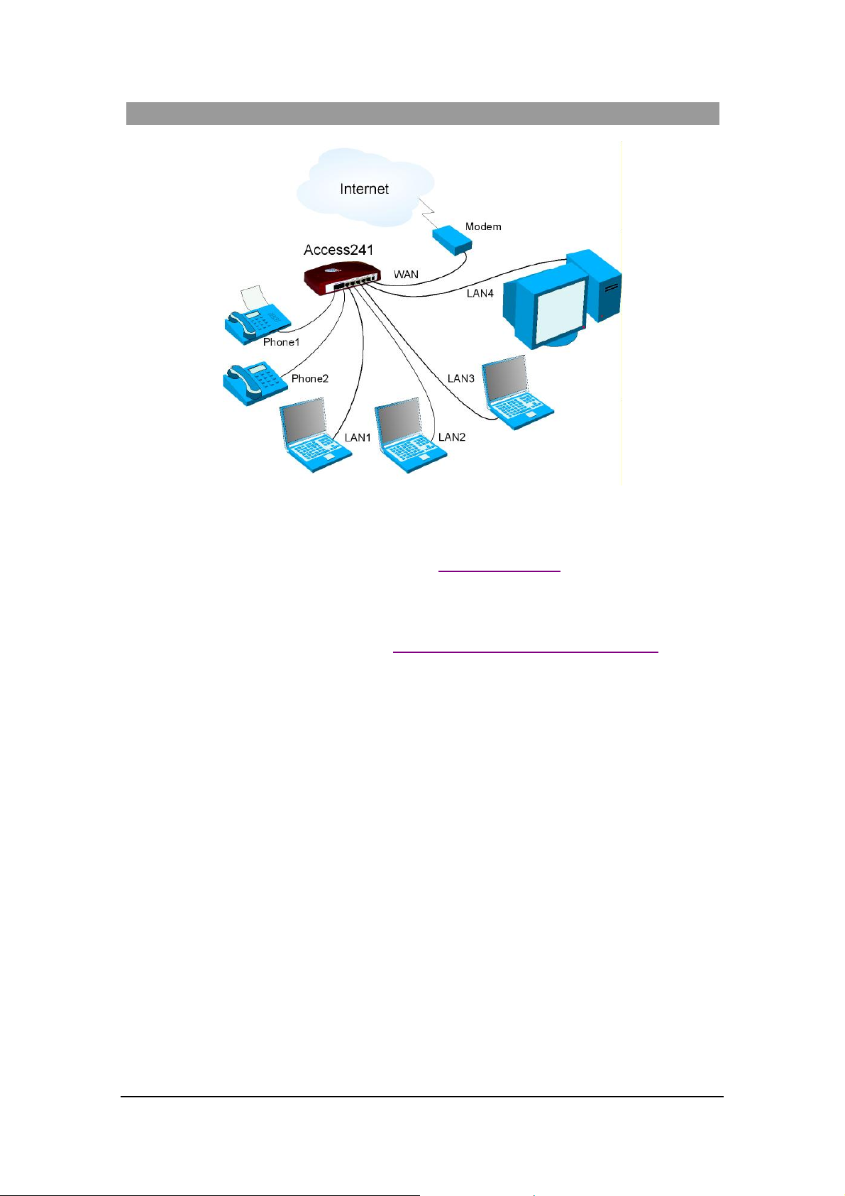
The Access 241 (AC-241) is a terminal Voice-over-IP (VoIP) WAN gateway device. The
Access 241 has two ph one ports, which enable you to conn ect one o r t wo independent analog
t elephone or Fax lines and communicat e o ve r the I ntern et or In tranet.
In additi on, there a re 1 WAN and 4 LAN ports; all a re 10/100Mbps Ethe rnet ports. The WAN port
connects to your mode m and the LAN ports c onnect to up to 4 PCs .
T he Access 241 s upports all st andard analog DT MF telephones an d accessories, includin g:
• Single-line touch-tone t elephones.
• Multiple-li ne touch- tone tel ephones.
• T ouch -t one te lephone s with redial or speed-dial feature s .
• P hones or accessor ies that support Caller ID.
• Answering machines with touch-tone support.
• P hones or accessor ies that support Dist inctive Ring.
NOTE Pul se-dial te lephones and ac cessories are not supported.
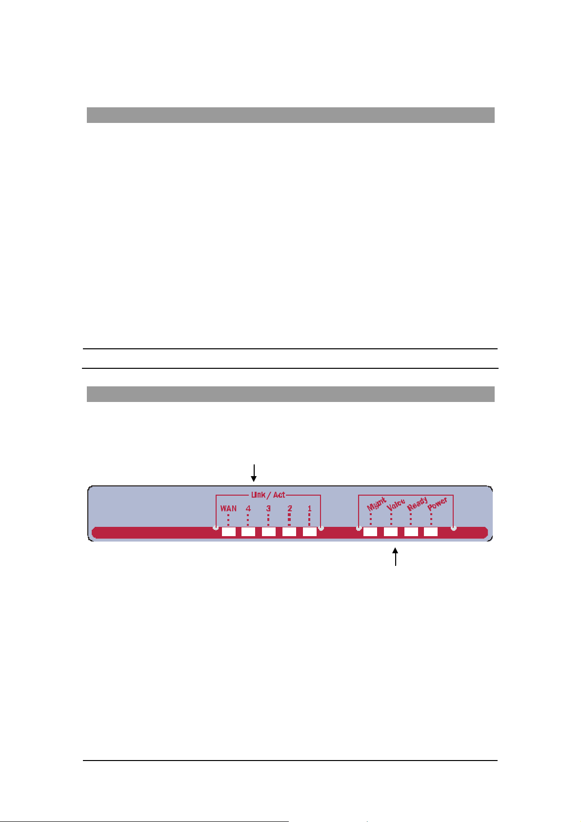
T he Front Pa nel
T he Access 241 Gatewa y’s fr ont pan el contains ni ne LEDs :
• Five link LEDs indicate Link and Activity st atus for the WAN and LAN ports. St eady
glow indicat e s Link, and blinking indicate s Activity.
Four s tatus LEDs provide operati ng information e xplai ned in the followi ng t abl e.
11
MN100129 Rev E
ACCES S 241-FXO/ 241/ 211/ 211N VOIP GATEWAY USER GUIDE
Sta t u s LED Indic at o r s
LED Mod e H .323 , MGC P, SIP St at u s Do wnlo ader St at us
Power
Ready
Voice
Steady glow Power OK Power OK
Blinking Application OK Loader OK
Steady glow Gateway registered with Gatekeeper
/ Call Agen t / SIP Server
Mngt
LAN
(1,2,3,4 )
WAN
Blinking Management activity Management activity
Steady Glow
Bli nking
Steady Glow
Bli nking
Link is up
LAN Activity
Link is up
WAN Acti vity
Link is up
LAN Activity
Link is up
WAN Acti vity
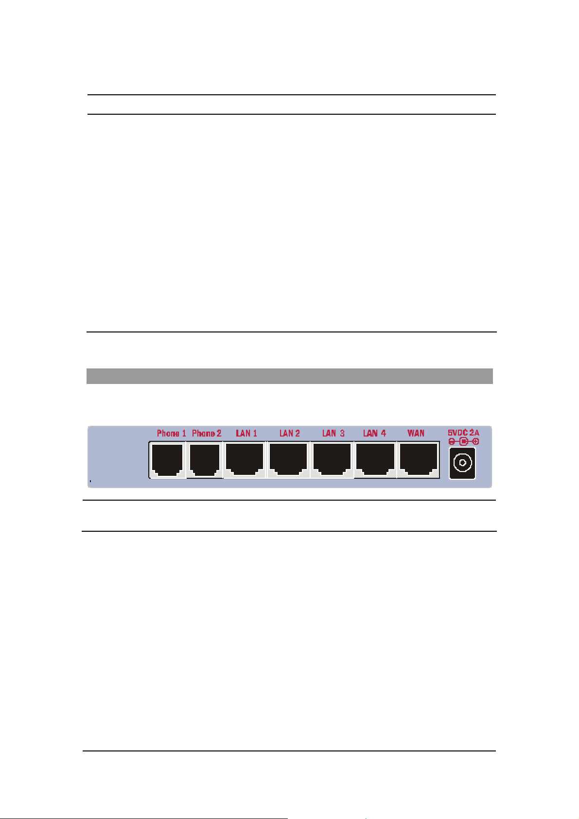
The Rear Panel
T he r ea r panel contain s the phone connecto rs, one W AN, four L AN connecto rs and t he input D C
powe r con nect or , a s shown in th e followi ng fi g ure.
CAUTION Never connect the Phone connectors to the public telephone outle t, or to
each other.
12
MN100129 Rev E

ACCES S 241-FXO/ 241/ 211/ 211N VOIP GATEWAY USER GUIDE
Before You Install
Be fore you begin t o in stall your Ac ce s s 241 VoIP Ga t eway, m ake sure that the temp erature and
humidi ty of the opera ting envir onme n t ar e ke p t w ithi n the foll owing lim i ts:
Ambie nt temperature: 0°C - 45°C (32°F - 113°C)
Humidi ty: 10% - 90% non-condensi ng
Required Equipment List
• Optionally, up to four PC s or l aptop c omput e rs wit h LAN card, we b browser and
Telnet.
• One 10/100 BaseTX ( RJ-45) Eth ernet cable (sup plied) for the Ethernet connection
fro m the Ac ces s 2 41 G atew ay to you r route r or mod e m.
• Add i tional 10/100Bas eTX (RJ -4 5) E the r ne t ca b l es (n ot s u ppl ie d ) t o co nn ect the
Gateway to the computers.
• Two push-button te le phon es with DTMF (tone signal) capa bility (not supplie d).
• An AC/5VDC power adapt er (sup plied).
The Access 241 Gateway must be powered by an external UL listed limited
power source or Class I I power source (AC/DC ada pter), rated input: 100 240 V, 47-63Hz, 0.5A, output: 5VDC @ 2A.
The phone ports (P hone1 and Phone2) a re intende d for i ndoor connections
only and must not be connec te d to the Public Telecommunicati on Network .
13
MN100129 Rev E
ACCES S 241-FXO/ 241/ 211/ 211N VOIP GATEWAY USER GUIDE
Installing your Access 241 V oIP Gateway
1. Unpack the Access 241 Gateway unit.
2. Verify you have the components listed in the Required Equipme nt
3. Place the Gat eway on a desktop or other level surface, or mo unt it on a wall. Choose a
loc a tio n tha t is nea r the devi ces t o be co n ne c ted and close to a n elec trical outl e t. If you w an t
to mount the unit on the wall , refe r to De tails fo r Wa ll Mounti ng th e G a tew a y Uni t
4. Connect the W AN port on the Gateway’s rear panel to the Ethernet socket on your
br oadband modem using an Ethernet ca ble.
5. Connect the LAN port on the G ateway’s rea r pa nel to the ne twork socket on your PC using
an Ethernet cable.
6. Connect addi tional PCs to the other LAN ports as described in the previ ous s tep.
7. Us e Phone cables to conne ct the telephones to the Ph one1 and P hone2 ports on t he rear of
the G ateway. (If your provider enables only one phone li ne, connect the phone to the Phone1
port)
li st above.
.
It is possible to connect u p to fi ve phones in pa rall el to each phone port. To d o so, conne ct a
5 -way sp litter to th e phone po rt. (If y o ur prov i der en able s o nl y one ph one l ine, use th e
Phon e 1 po rt on t he G a te way).
8. V erify that al l s ys tem components are properl y ins talled. Make sure that all cable connectors
are securely positioned in t he appropriate ports .
14
MN100129 Rev E

ACCES S 241-FXO/ 241/ 211/ 211N VOIP GATEWAY USER GUIDE
9 . C onne ct th e po wer adapte r t o th e Gateway’ s po wer conn ecto r on t he rear of t he un it .
Conn ect the p o wer adapt er to a wall sock et .
10. Check that the Power LED on the Gat eway’s front panel glows steadily.
12 . Tur n on the PC s . F or e ach PC pe r f orm t he followi ng :
12a. If you are using a DSL modem, you will need to enable PPPoE on the Gateway and disable
PPPoE on the PC. To e nab l e PPPoE on the G a tew a y:
9) Open the web browser and put the IP of the Gateway in the address field (the
fact ory default IP address of the LAN interface is 192.168.100.1).
10) In the vertical menu bar on the left of t he Gate wa y Web page, s elect WAN.
The WAN Status page a ppears.
11) In t he h orizont al menu bar of t he WAN p age, select PPPoE. The W AN PPPoE
Configuration page appears.
12) Select Yes in the Enable PPP oE dro p-down l ist box.
13) Fill in the username an d passwor d in th e Authentication fields as suppli ed by y our
DSL p rovider. Optio nally you can enter th e service nam e for the requested service.
To select a specific provider, enter his access name in the AC n ame field.
14) Click Save PPPoE Settings .
15) After entering and saving all configurations, you must reset the Gateway. In the
vertical menu b ar of the curren t pag e, s elec t Reset. The Reset page appears.
16) Select Power on reset and click the Reset butt on. T h e Gateway p ower cy cles and
the application’s home page opens with the new configuration settings.
For more information see section “Enabling P oint-to-Point Protocol over Ethernet
(PPPoE)”.
12 b. If you ar e usin g a cable modem, note th at some cable modems need to be powered off an d
then on after being connected t o th e Gate way . For such modems you can also power off the
Gatewa y and then power on for fas ter connec tion.
13 . Wait f or the Voice LED on the Gateway front panel to glow, indicating connection to your
I nternet an d Vo IP prov i der s. It m ay t ake a m in ut e or t wo for t h ese conn ect ion s t o be
established.
14. Verify that your broadband Internet s ervice functions properl y.
15. Pick up the phone on each li ne to verify that you c an hear the dial tone .
On ce the in stallation is complete , y ou can use your Gateway for telephone calls and for the Internet,
as s uming t hat you h ave a con nec ti o n suppli ed by y our V oI P pro vi d er.
If any problems are experie nced during the ins tall ation of the uni t, please contact you r l oc al vend or.
15
MN100129 Rev E
 Loading...