


ACCESS 241-FXO
ACCESS 241
ACCESS 211
ACCESS 211N
(AC-241-FXO/AC-241/AC-211/AC-211N)
VOIP GATEWAY USER GUIDE
MN100129 Rev E

ACCES S 241-FXO/ 241/ 211 VOIP GATEWAY USER GUIDE
Revision History
Revision Date Description
A01 April 01, 2004 1. Adapted for UL/FCC
2. Section 10.4 formerly for H.323 and SIP i s now
separated – now Section 10.4 for SIP with revised rules
for Hold call, Call waiting, Transfer call, and Conference
(flash without followin g di gits), and Section 1 0.5 for
H.323 with contents as before.
B March 02, 2005 Adapted for Version 4.53.29
C Jul y 2005 Added AC-241 to AC-211 support.
Adapted for Version 4.56
D Sept e mber 20 05 Add ed AC - 241- F X O.
Adapted for AC-241FXO versi on 5.1,
AC-241 and AC-211 version 4.57
E Nov em ber 200 5 Add ed AC - 211N suppor t . This rev is ion of A C- 211N
accommodates s/w version 4.57
Co pyr ight © Te lc o Sy st em s, Lt d. , 2005. A ll r ight s r eserv ed. Al l tr adem ark s ar e pro pe rty of the ir
respective ow ners. No part of this documenta tion may be reproduced in any form or by any means
o r used t o make any der ivat iv e wo rk ( such a s t ran slat io n, tr ans format ion, or adapt ation) wit ho ut
permis s ion from Te lco Syst ems, Ltd.
T he informat ion and spe cification s in t hi s guide are subject t o change without prio r noti ce .
2
MN100129 Rev E

ACCES S 241-FXO/ 241/ 211 VOIP GATEWAY USER GUIDE
T able o f Co nten ts
INTRODUCTION............................................................................................................. 5
TERMINOLOGY................................................................................................................. 5
HOW TO GET HELP............................................................................................................ 5
ACCESS 241-FXO OVERVIEW AND I NS T ALL AT IO N...................................................... 6
OVERVIEW ...................................................................................................................... 6
THE FRONT PANEL............................................................................................................ 6
THE REAR PANEL.............................................................................................................. 7
BEFORE YOU INSTALL ....................................................................................................... 7
Required Equipment List.................................................................................................8
INSTALLING YOUR ACCESS 241-FXO VOIP GATEW A Y ............................................................. 9
ACCESS 241 OVE RVI E W AND I NS T AL L ATIO N..............................................................11
OVERVIEW .....................................................................................................................11
THE FRONT PANEL...........................................................................................................11
THE REAR PANEL.............................................................................................................12
BEFORE YOU INSTALL ......................................................................................................13
Required Equipment List................................................................................................13
INSTALLING YOUR ACCESS 241 VOIP GATEWAY....................................................................14
ACCESS 211 AND ACCES S 211N OVERVIEW AND INST ALLATIO N...............................16
OVERVIEW .....................................................................................................................16
THE FRONT PANEL...........................................................................................................17
Access 211 ..................................................................................................................17
Access 211N ................................................................................................................18
THE REAR PANEL.............................................................................................................19
Access 211 ..................................................................................................................19
Access 211N ................................................................................................................19
BEFORE YOU INSTALL ......................................................................................................20
Required Equipment List................................................................................................20
INSTALLING YOUR ACCESS 211/ACCESS 211N VOIP GATEWAY WITH A SINGLE PC.......................21
INSTA LLING YOUR ACCESS 211/ACCESS 211N VOIP GATEWAY WITH A HOME NETWORK ..............23
WALL-MOUNTING THE GATEWAY UNIT.....................................................................25
USING THE GATEWAY..................................................................................................26
FIRST CALL....................................................................................................................26
PST N PORT CALLING WITH ACCESS 241-FXO.......................................................................26
PSTN Outgoing Calls....................................................................................................26
PSTN Incoming Calls....................................................................................................26
PSTN Call Behavior during Unit Power-down or Inactive VoIP Service (Voice LED is off).........26
LIFE LINE PORT CA LLING WIT H ACCESS 241 AND ACCE SS 211 ..................................................26
Life-line Port Calls during Unit Power-down or Inactive VoIP Service (Voice LED is off)..........26
ADVANCED CALLING FEATURES FOR SIP..............................................................................26
Ca ll Wai tin g................................................................................................................27
Caller ID Display, Caller Identity on Call W aiting..............................................................27
Conference Call ...........................................................................................................27
Call Forwarding...........................................................................................................27
Condit ional Call Forwarding..........................................................................................27
Attended Transfer Call...................................................................................................27
Blind Transfer Call .......................................................................................................27
Hold...........................................................................................................................27
Do Not Disturb (DND) ..................................................................................................28
3
MN100129 Rev E

ACCES S 241-FXO/ 241/ 211 VOIP GATEWAY USER GUIDE
Red i a l ing o f La s t Recei ved Cal l .......................................................................................28
Bl o ck Las t Recei ved Call er.............................................................................................28
Auto Redial..................................................................................................................28
Block Caller ID ............................................................................................................28
Anonymous Cal l Rejection..............................................................................................28
ADVANCED CALLING FEATURES FOR H.323...........................................................................28
Ca ll Wai tin g................................................................................................................28
Conference Call ...........................................................................................................29
Call Forwarding...........................................................................................................29
Transferring a Call .......................................................................................................29
Hold...........................................................................................................................29
ADVANCED CALLING FEATURES FOR MGCP .........................................................................29
ADVANCED CO NFI G URAT I O N VIA T H E W EB..............................................................30
WAN CONFIGURATION.....................................................................................................30
ENABLING POINT-TO-POINT PROTOCOL OVER ETHERN ET (PPPOE).............................................33
ENABLING POINT-TO-POINT T PROTOCOL (PPTP)...................................................................34
MAC SPOOFING ..............................................................................................................34
LAN CONFIGURATION......................................................................................................35
Configuring LAN Settings...............................................................................................36
DHCP Server Configuration...........................................................................................37
Port Forwarding..........................................................................................................39
Enabling the Network Address Translator (NAT)................................................................40
SECURI TY CONFIGURATION................................................................................................42
LINE CONFIGURATION ......................................................................................................43
Call Forward Line Configuration....................................................................................43
Gain Control Configuration (Volume) ..............................................................................43
COMPLETING THE GATEWAY CONFIGURATION.......................................................................46
TROUBLESHOOTING....................................................................................................47
SPECIFICATIONS..........................................................................................................48
4
MN100129 Rev E

ACCES S 241-FXO/ 241/ 211 VOIP GATEWAY USER GUIDE
Introdu ctio n
Thank you f or purchas ing this pr oduc t. W e a t Tel c o S ys te ms a re confide n t th a t y ou w ill ob tain full
satisfaction from your new VoIP gateway. Pl ease read this guide carefully i n order to ma ke use of
all the advanced feat ures provided by this product.
Th is guide is intended for users connecting to th e Internet or Intranet with VoIP service set up by a
VoIP provider and the Acce ss 241-FXO/Acce s s 241/Ac ces s 211/ Acce s s 211N Gateway fa ctory
pre-co nfigu red . If this is no t th e c ase , refe r to the ad mi nistra to r's manual.
Terminology
T hrougho ut this guide, t he Acc ess 241 -FXO, Acce ss 241 , Access 211 an d A ccess 211N will be
ref erred to as “the Gateway”, excluding cases when referring specif ically to the Access 241-FXO,
the Access 241, Access 211 or Access 211N.
How to Ge t Help
For technical support, pleas e contact the local distribu tor that su pplied the u ni t.
5
MN100129 Rev E
ACCES S 241-FXO/ 241/ 211 VOIP GATEWAY USER GUIDE
Access 241 -FX O Ov ervi ew a nd I nsta lla tion
Overview
T he A cc es s 241 -FX O (A C- 241-F XO) i s a t erm in a l Voice-o ver- IP ( VoIP) W A N gatewa y devic e
an d t elephon e a dapto r. T he A cce ss 24 1- FXO h as t wo in depen dent phone po rt s (FXS) an d on e
PSTN port ( FXO) . The FXS phon e ports e nable yo u to connect one or two independent analo g
telephone or Fax lines and communicate over the Internet Intranet. The PSTN (FXO) port is used to
connect to the Publ ic Switc hed T elephone Network. (PSTN ). T he combination of both F XS and
FX O po rts e nabl es us in g yo ur t eleph one t o co mm unic at e ov er th e i nternet , int ran et and p ubli c
telephone netw ork.
The Access 241-FXO has 1 WAN and 4 LAN ports; all a re 10/100Mbps Ethernet ports. The WAN
port connects to your modem and the LAN ports c onnect to up to 4 PCs .
T he Access 241-FXO s upports all stan dard analog DTM F tele phone s and acce s so ri es, including:
• Single-line touch-tone t elephones.
• Multiple-li ne touch- tone tel ephones.
• T ouch -t one te lephone s with redial or speed-dial feature s .
• P hones or accessor ies that support Caller ID.
• Answering machines with touch-tone support.
• P hones or accessor ies that support Dist inctive Ring.
NOTE Pul se-dial te lephones and ac cessories are not supported.
T he Front Pa nel
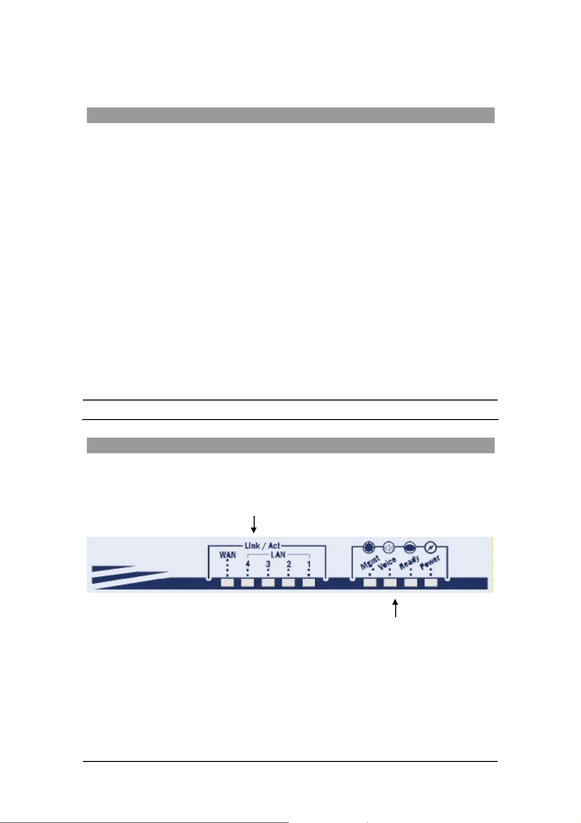
The Access 241-FXO Gateway’s front panel contains nine LEDs:
• Five link LEDs indicate Link and Activity st atus for the WAN and LAN ports. St eady
glow indicat e s Link, and blinking indicate s Activity.
Four s tatus LEDs provide operati ng information e xplai ned in the followi ng t abl e.
6
MN100129 Rev E
ACCES S 241-FXO/ 241/ 211/ 211N VOIP GATEWAY USER GUIDE
Sta t u s LED Indic at o r s
LED Mod e H .323 , MGC P, SIP St at u s Do wnlo ader St at us
Power
Ready
Voice
Mngt
LAN
(1,2,3,4 )
WAN
Steady glow Power OK Power OK
Blinking Application OK Loader OK
Steady glow Gateway registered with Gatekeeper
/ Call Agen t / SIP Server
Blinking Management activity Management activity
Steady Glow
Bli nking
Steady Glow
Bli nking
Link is up
LAN Activity
Link is up
WAN Acti vity
Link is up
LAN Activity
Link is up
WAN Acti vity
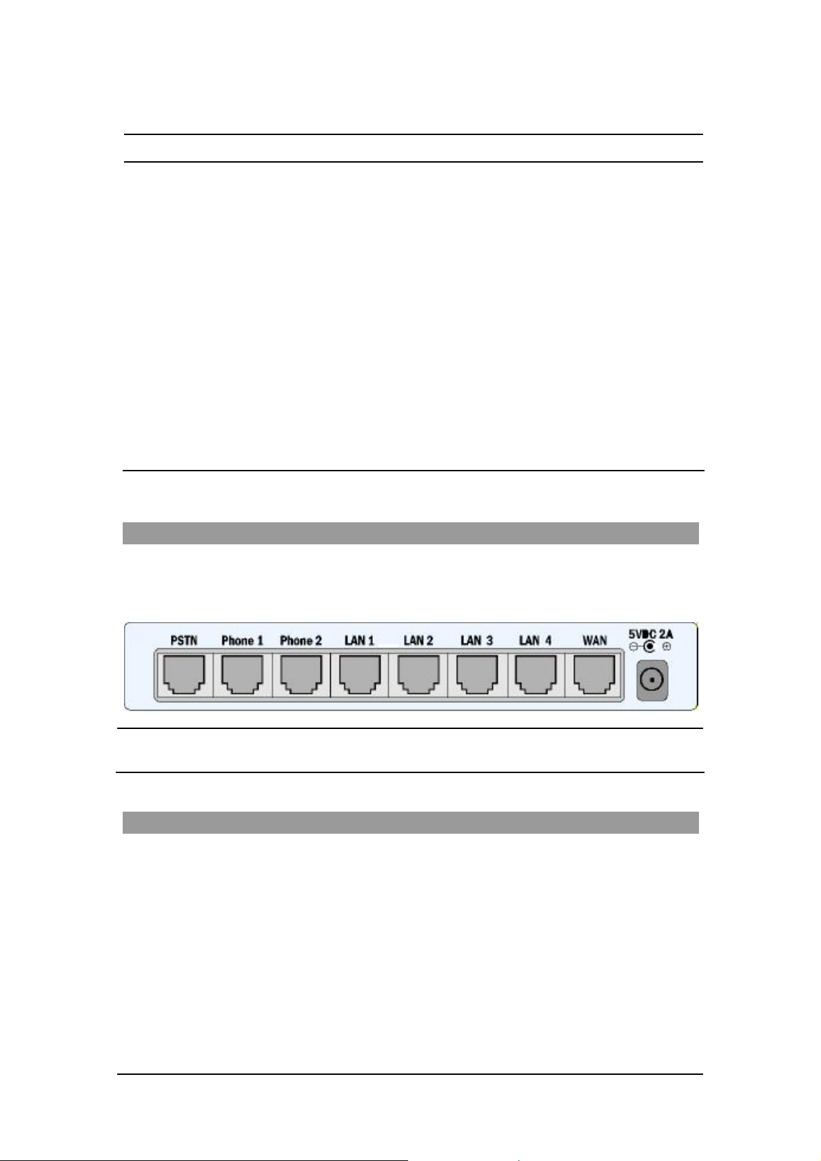
The Rear Panel
T he r ea r panel contain s the phone connecto rs, one W AN, four L AN connecto rs and t he input D C
po wer connector , as sho wn in the follo wing f igur e. The PSTN socket on the left is designed to
provide a public telephone network connec tion.
CAUTION Never connect the Phone1 and P hone2 connectors to the public tele phone
outlet, or to e ac h othe r .
Before You Install
Be fore you begin t o in stall your Ac ce s s 241 VoIP Ga t eway, m ake sure that the temp erature and
humidi ty of the opera ting envir onme n t ar e ke p t w ithi n the foll owing lim i ts:
Ambie nt temperature: 0°C - 45°C (32°F - 113°C)
Humidi ty: 10% - 90% non-condensi ng
7
MN100129 Rev E

ACCES S 241-FXO/ 241/ 211/ 211N VOIP GATEWAY USER GUIDE
Required Equipment List
• Optionally, up to four PC s or l aptop c omput e rs wit h LAN card, we b browser and
Telnet.
• One 10/100 BaseTX ( RJ-45) Eth ernet cable (sup plied) for the Ethernet connection
fro m the Ac ces s 2 41 G atew ay to you r route r or mod e m.
• Add i tional 10/100Bas eTX (RJ -4 5) E the r ne t ca b l es (n ot s u ppl ie d ) t o co nn ect the
Gateway to the computers.
• Two push-button te le phon es with DTMF (tone signal) capa bility (not supplie d).
• An AC/5VDC power adapt er (sup plied).
The Access 241 Gateway must be powered by an external UL listed limited
power source or Class I I power source (AC/DC ada pter), rated input: 100 240 V, 47-63Hz, 0.5A, output: 5VDC @ 2.6A.
The phone ports (P hone1 and Phone2) a re intende d for i ndoor connections
only and must not be connec te d to the publ ic tel ephone network.
ONLY the PSTN port can be connected to the public tel ephone network
outlet.
8
MN100129 Rev E

ACCES S 241-FXO/ 241/ 211/ 211N VOIP GATEWAY USER GUIDE
Installing your Access 241-FXO VoIP Gateway
1. Unpack the Gateway unit.
2. Verify you have the components listed in the Required Equipme nt
3. Place the Gat eway on a desktop or other level surface, or mo unt it on a wall. Choose a
loc a tio n tha t is nea r the devi ces t o be co n ne c ted and close to a n elec trical outl e t. If you w an t
to mount the unit on the wall , refe r to De tails fo r Wa ll Mounti ng th e G a tew a y Uni t
4. Connect the W AN port on the Gateway’s rear panel to the Ethernet socket on your
br oadband modem using an Ethernet ca ble.
5. Connect a LAN port on the Gatew ay’s rea r panel to the network socket on your PC using an
E th er n e t cable.
6. Connect addi tional PCs to the other LAN ports as described in the previ ous s tep.
7. Us e Phone cables to conne ct the telephones to the Ph one1 and P hone2 ports on t he rear of
the G ateway. (If your provider enables only one phone li ne, connect the phone to the Phone1
port)
li st above.
.
It is possible to connect u p to fi ve phones in pa rall el to each phone port. To d o so, conne ct a
5 -way sp litter to th e phone po rt. (If y o ur prov i der en able s o nl y one ph one l ine, use th e
Phon e 1 po rt on t he G a te way).
8 Conn ec t the Phone cab l e fro m the PSTN wall socke t to the G a tew ay’s PSTN port.
9
MN100129 Rev E

ACCES S 241-FXO/ 241/ 211/ 211N VOIP GATEWAY USER GUIDE
9. V erify that al l s ys tem components are properl y ins talled. Make sure that all cable connectors
are securely positioned in t he appropriate ports .
1 0. Co nnect th e po we r a dapter to t he Gat eway’ s po we r conn ect o r on t he re ar of th e un it .
Conn ect the p o wer adapt er to a wall sock et .
11. Check that the Power LED on the Gat eway’s front panel glow steadily.
12 . Tur n on the PC s . F or e ach PC pe r f orm t he followi ng :
12a. If you are using a DSL modem, you will need to enable PPPoE on the Gateway and disable
PPPoE on the PC. To e nab l e PPPoE on the G a tew a y:
1) Open the web browser and put the IP of the Gateway in the address field (the
fact ory default IP address of the LAN interface is 192.168.100.1).
2) I n th e vertical menu bar on the left of t he Gate wa y Web page, s elect WAN.
The WAN Status page a ppears.
3) In th e horizont al menu bar of t he WAN page, select PPPoE. The W AN PPPoE
Configuration page appears.
4) Select Yes in the Enable PPP oE dr op-do wn li s t box.
5) Fill in the username and password in t he Authentication fields as supplied by your
DSL p rovider. Optio nally you can enter th e service nam e for the requested service.
To select a specific provider, enter his access name in the AC n ame field.
6) Click Save PPPo E Settings.
7) After entering and saving all configurations, you must reset the Gateway. In t he
vertical menu b ar of the curren t pag e, s elec t Reset. The Reset page appears.
8) Select Power on rese t and click t he Reset button. Th e Gateway power cycles and
the application’s home page opens with the new configuration settings.
For more information see section “Enabling P oint-to-Point Protocol over Ethernet
(PPPoE)”.
12 b. If you ar e usin g a cable modem, note th at some cable modems need to be powered off an d
then on after being connected t o th e Gate way . For such modems you can also power off the
Gatewa y and then power on for fas ter connec tion.
13 . Wait f or the Voice LED on the Gateway front panel to glow, indicating connection to your
I nternet an d Vo IP prov i der s. It m ay t ake a m in ut e or t wo for t h ese conn ect ion s t o be
established.
14. Verify that your broadband Internet s ervice functions properl y.
15. Pick up the phone on each li ne to verify that you c an hear the dial tone .
On ce the in stallation is complete , y ou can use your Gateway for telephone calls and for the Internet,
as s uming t hat you h ave a con nec ti o n suppli ed by y our V oI P pro vi d er.
If any problems are experie nced during the ins tall ation of the uni t, please contact you r l oc al vend or.
10
MN100129 Rev E
ACCES S 241-FXO/ 241/ 211/ 211N VOIP GATEWAY USER GUIDE
Access 241 O verv iew and Inst all atio n
Overview
The Access 241 (AC-241) is a terminal Voice-over-IP (VoIP) WAN gateway device. The
Access 241 has two ph one ports, which enable you to conn ect one o r t wo independent analog
t elephone or Fax lines and communicat e o ve r the I ntern et or In tranet.
In additi on, there a re 1 WAN and 4 LAN ports; all a re 10/100Mbps Ethe rnet ports. The WAN port
connects to your mode m and the LAN ports c onnect to up to 4 PCs .
T he Access 241 s upports all st andard analog DT MF telephones an d accessories, includin g:
• Single-line touch-tone t elephones.
• Multiple-li ne touch- tone tel ephones.
• T ouch -t one te lephone s with redial or speed-dial feature s .
• P hones or accessor ies that support Caller ID.
• Answering machines with touch-tone support.
• P hones or accessor ies that support Dist inctive Ring.
NOTE Pul se-dial te lephones and ac cessories are not supported.
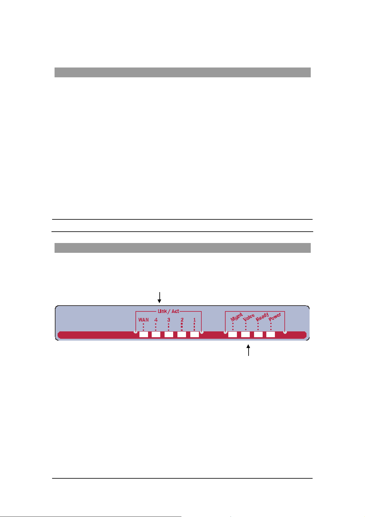
T he Front Pa nel
T he Access 241 Gatewa y’s fr ont pan el contains ni ne LEDs :
• Five link LEDs indicate Link and Activity st atus for the WAN and LAN ports. St eady
glow indicat e s Link, and blinking indicate s Activity.
Four s tatus LEDs provide operati ng information e xplai ned in the followi ng t abl e.
11
MN100129 Rev E
ACCES S 241-FXO/ 241/ 211/ 211N VOIP GATEWAY USER GUIDE
Sta t u s LED Indic at o r s
LED Mod e H .323 , MGC P, SIP St at u s Do wnlo ader St at us
Power
Ready
Voice
Steady glow Power OK Power OK
Blinking Application OK Loader OK
Steady glow Gateway registered with Gatekeeper
/ Call Agen t / SIP Server
Mngt
LAN
(1,2,3,4 )
WAN
Blinking Management activity Management activity
Steady Glow
Bli nking
Steady Glow
Bli nking
Link is up
LAN Activity
Link is up
WAN Acti vity
Link is up
LAN Activity
Link is up
WAN Acti vity
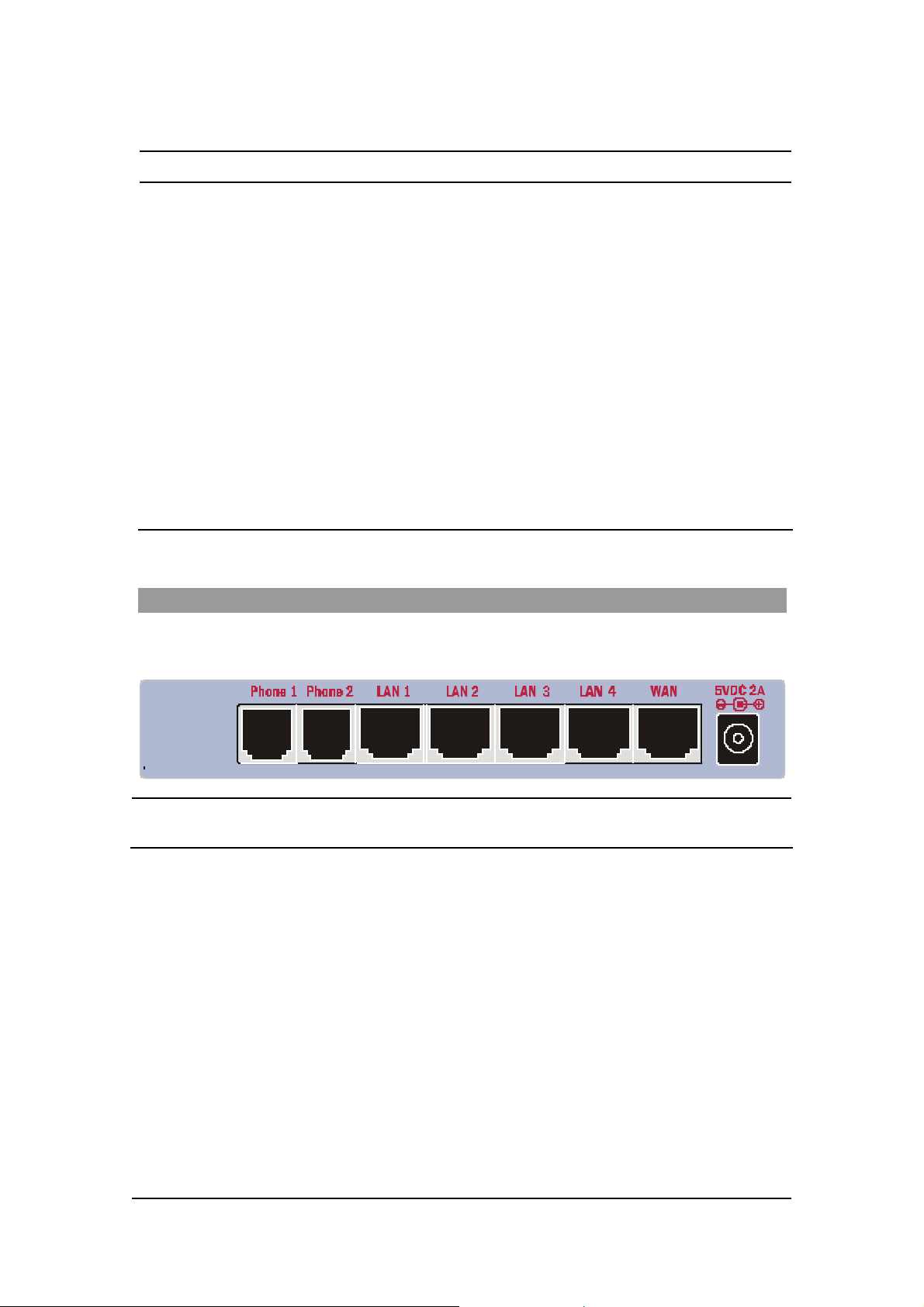
The Rear Panel
T he r ea r panel contain s the phone connecto rs, one W AN, four L AN connecto rs and t he input D C
powe r con nect or , a s shown in th e followi ng fi g ure.
CAUTION Never connect the Phone connectors to the public telephone outle t, or to
each other.
12
MN100129 Rev E

ACCES S 241-FXO/ 241/ 211/ 211N VOIP GATEWAY USER GUIDE
Before You Install
Be fore you begin t o in stall your Ac ce s s 241 VoIP Ga t eway, m ake sure that the temp erature and
humidi ty of the opera ting envir onme n t ar e ke p t w ithi n the foll owing lim i ts:
Ambie nt temperature: 0°C - 45°C (32°F - 113°C)
Humidi ty: 10% - 90% non-condensi ng
Required Equipment List
• Optionally, up to four PC s or l aptop c omput e rs wit h LAN card, we b browser and
Telnet.
• One 10/100 BaseTX ( RJ-45) Eth ernet cable (sup plied) for the Ethernet connection
fro m the Ac ces s 2 41 G atew ay to you r route r or mod e m.
• Add i tional 10/100Bas eTX (RJ -4 5) E the r ne t ca b l es (n ot s u ppl ie d ) t o co nn ect the
Gateway to the computers.
• Two push-button te le phon es with DTMF (tone signal) capa bility (not supplie d).
• An AC/5VDC power adapt er (sup plied).
The Access 241 Gateway must be powered by an external UL listed limited
power source or Class I I power source (AC/DC ada pter), rated input: 100 240 V, 47-63Hz, 0.5A, output: 5VDC @ 2A.
The phone ports (P hone1 and Phone2) a re intende d for i ndoor connections
only and must not be connec te d to the Public Telecommunicati on Network .
13
MN100129 Rev E
ACCES S 241-FXO/ 241/ 211/ 211N VOIP GATEWAY USER GUIDE
Installing your Access 241 V oIP Gateway
1. Unpack the Access 241 Gateway unit.
2. Verify you have the components listed in the Required Equipme nt
3. Place the Gat eway on a desktop or other level surface, or mo unt it on a wall. Choose a
loc a tio n tha t is nea r the devi ces t o be co n ne c ted and close to a n elec trical outl e t. If you w an t
to mount the unit on the wall , refe r to De tails fo r Wa ll Mounti ng th e G a tew a y Uni t
4. Connect the W AN port on the Gateway’s rear panel to the Ethernet socket on your
br oadband modem using an Ethernet ca ble.
5. Connect the LAN port on the G ateway’s rea r pa nel to the ne twork socket on your PC using
an Ethernet cable.
6. Connect addi tional PCs to the other LAN ports as described in the previ ous s tep.
7. Us e Phone cables to conne ct the telephones to the Ph one1 and P hone2 ports on t he rear of
the G ateway. (If your provider enables only one phone li ne, connect the phone to the Phone1
port)
li st above.
.
It is possible to connect u p to fi ve phones in pa rall el to each phone port. To d o so, conne ct a
5 -way sp litter to th e phone po rt. (If y o ur prov i der en able s o nl y one ph one l ine, use th e
Phon e 1 po rt on t he G a te way).
8. V erify that al l s ys tem components are properl y ins talled. Make sure that all cable connectors
are securely positioned in t he appropriate ports .
14
MN100129 Rev E

ACCES S 241-FXO/ 241/ 211/ 211N VOIP GATEWAY USER GUIDE
9 . C onne ct th e po wer adapte r t o th e Gateway’ s po wer conn ecto r on t he rear of t he un it .
Conn ect the p o wer adapt er to a wall sock et .
10. Check that the Power LED on the Gat eway’s front panel glows steadily.
12 . Tur n on the PC s . F or e ach PC pe r f orm t he followi ng :
12a. If you are using a DSL modem, you will need to enable PPPoE on the Gateway and disable
PPPoE on the PC. To e nab l e PPPoE on the G a tew a y:
9) Open the web browser and put the IP of the Gateway in the address field (the
fact ory default IP address of the LAN interface is 192.168.100.1).
10) In the vertical menu bar on the left of t he Gate wa y Web page, s elect WAN.
The WAN Status page a ppears.
11) In t he h orizont al menu bar of t he WAN p age, select PPPoE. The W AN PPPoE
Configuration page appears.
12) Select Yes in the Enable PPP oE dro p-down l ist box.
13) Fill in the username an d passwor d in th e Authentication fields as suppli ed by y our
DSL p rovider. Optio nally you can enter th e service nam e for the requested service.
To select a specific provider, enter his access name in the AC n ame field.
14) Click Save PPPoE Settings .
15) After entering and saving all configurations, you must reset the Gateway. In the
vertical menu b ar of the curren t pag e, s elec t Reset. The Reset page appears.
16) Select Power on reset and click the Reset butt on. T h e Gateway p ower cy cles and
the application’s home page opens with the new configuration settings.
For more information see section “Enabling P oint-to-Point Protocol over Ethernet
(PPPoE)”.
12 b. If you ar e usin g a cable modem, note th at some cable modems need to be powered off an d
then on after being connected t o th e Gate way . For such modems you can also power off the
Gatewa y and then power on for fas ter connec tion.
13 . Wait f or the Voice LED on the Gateway front panel to glow, indicating connection to your
I nternet an d Vo IP prov i der s. It m ay t ake a m in ut e or t wo for t h ese conn ect ion s t o be
established.
14. Verify that your broadband Internet s ervice functions properl y.
15. Pick up the phone on each li ne to verify that you c an hear the dial tone .
On ce the in stallation is complete , y ou can use your Gateway for telephone calls and for the Internet,
as s uming t hat you h ave a con nec ti o n suppli ed by y our V oI P pro vi d er.
If any problems are experie nced during the ins tall ation of the uni t, please contact you r l oc al vend or.
15
MN100129 Rev E

ACCES S 241-FXO/ 241/ 211/ 211N VOIP GATEWAY USER GUIDE
Access 211 and Acc ess 211N O verv iew and Insta lla tion
Overview
The Access 211 and Access 211N (AC-211/AC-211N) are term inal Voice over IP (VoIP) WAN
Gat eway devices. The VoIP function alities are available with a regular analog telephone. The
Access 211N is physically smaller than the Access 211; however both units share similar
functionality, unless otherwise stated. The information in this chapter refers to both units.
The Access 211/Access 211N has two phone ports, which enable you to connect one or two
indepe ndent regular telephone or Fax li nes and communicate over the Internet or Intranet. You can
connect up to 5 phones in paral lel.
Fo r Acce ss 21 1, yo u c an conne ct a r e gular t elephon e line to th e Gat eway’ s L if e li ne port . T h is
ensures continu ous telephone service i n the event of a power ou tage or a VoIP netw ork failu re.
NOTE Access 211N does not suppor t Li fe Line Operation.
T he Gateway ha s one WAN and one LAN port, both ar e 10/100Mbps Et hernet po rt s . The WAN
port connects to your modem and the LAN port connects to your PC.
The Access 211/Access 211N supports all standard analog DTMF telephon es and accessories,
inclu ding:
• Single-line touch-tone t elephones.
• Multiple-li ne touch- tone tel ephones.
• T ouch -t one te lephone s with redial or speed-dial feature s .
• P hones or accessor ies that support Caller ID.
• Answering machines with touch-tone support.
• P hones or accessor ies that support Dist inctive Ring.
NOTE Pul se-dial te lephones and ac cessories are not supported
16
MN100129 Rev E

ACCES S 241-FXO/ 241/ 211/ 211N VOIP GATEWAY USER GUIDE
T he Front Pa nel
Access 211
Th e Acc e s s 21 1 V oIP G atewa y has s ix LE Ds o n t he f ront pa nel :
• T wo link LEDs indicate Link and Activity st atus for the WAN and LAN. Steady glow
indicates Link, an d blinking indicate s Activity.
• Four status LE Ds provide op er atin g in formation.
Statu s LE D Indicato rs for Access 211
LED Mod e H .323 , MGC P, SIP St at u s Do wnlo ader St at us
Power
Ready
Voice
Mngt
LAN
WAN
Steady glow Power OK Power OK
Blinking Application OK Loader OK
Steady glow Gateway registered with Gatekeeper
/ Call Agen t / SIP Server
Blinking Management activity Management activity
Steady Glow
Bli nking
Steady Glow
Bli nking
Link is up
LAN Activity
Link is up
WAN Acti vity
Link is up
LAN Activity
Link is up
WAN Acti vity
17
MN100129 Rev E

ACCES S 241-FXO/ 241/ 211/ 211N VOIP GATEWAY USER GUIDE
Access 211N
The Access 211N VoI P Ga teway has si x LEDs on the front panel:
• T wo link LEDs indicate Link and Activity st atus for the WAN and LAN. Steady glow
indicates Link, an d blinking indicate s Activity.
• Two Phone LED s that indicate you a re conn ected to yo ur Vo IP s er vi ce provider s
• Power and Rea dy LEDs in di ca te the unit is powere d on an d appli cation is operating.
Statu s LE D Indicato rs for Access 211N
LED Mode H.323, MGC P, SIP Status Downloader Status
Power
Ready
Phone1 /
Phone 2
LAN
WAN
Steady glow Power OK Power OK
Stea dy gl ow App l icati on OK Loa der OK
Steady glow Gateway registered with Gatekeeper
/ Call Agen t / SIP Server
Steady Glow
Bli nking
Steady Glow
Bli nking
Link is up
LAN Activity
Link is up
WAN Acti vity
Link is up
LAN Activity
Link is up
WAN Acti vity
18
MN100129 Rev E

ACCES S 241-FXO/ 241/ 211/ 211N VOIP GATEWAY USER GUIDE
The Rear Panel
Access 211
The rear pa nel c ontai ns the phone c onnectors, (Phone1, Phone2 a nd Life Line) the LAN a nd WAN
conne ctors an d the input DC power connector , as shown in the fo llowing figure.
F i gu r e 1: Access 211 Back Panel
Life Line for Access 211 - The optional Life Line so cket on the left is designed to prov ide a public
ne two rk con nec ti on in th e e v e n t of powe r fa ilu re.
Never connect the Phone1,2 connectors to the publ i c te l ephone outlet, or
to each other. Only the Life Line connector, may be connecte d to the publ ic
telephone outl et.
Access 211N
The rear panel contains the phone connectors, (PH1 and PH2) the LAN and WAN connectors and
the input D C po we r connector, as sho wn in the f ollowing figure.
F i gu r e 2: Access 211N Back Panel
Never connect the Phone connectors to the public telephone outle t, or to
each other.
19
MN100129 Rev E

ACCES S 241-FXO/ 241/ 211/ 211N VOIP GATEWAY USER GUIDE
Before You Install
Before you begin to ins tall your VoIP Gateway, make sure that the tempe ra tu re and humidity of the
operat ing enviro nment are kep t within the foll o wing limits:
Ambie nt temperature: 0°C - 45°C (32°F - 113°C)
Humidi ty: 10% - 90% non-condensi ng
Required Equipment List
• Optionally, a PC or a lapt op computer with a LAN card, a web browser and Telnet.
• One 10/100 BaseTX ( RJ-45) Eth ernet cable (sup plied) for the Ethernet connection
f rom the Acces s 211 Gate way t o your router /switch or modem .
• One 10/100 BaseTX ( RJ-45) Eth ernet cable (not sup p lied) to connect the unit t o
your comput er devices.
• Two push-button te le phon es with DTMF (tone signal) capa bility (not supplie d).
• An AC/5VDC power adapt er (sup plied).
When using the Access 211/211N Gateway and the attached telephone set, basic safety
precautions should alw ays be fol lowed to reduce the ris k of fire, elec tric s ho ck an d
injury to persons, inclu ding the f ollowing:
1. Do not use this equi pme nt near wate r, f or exam pl e, near a bath tu b, wash bo wl,
kitchen sink or laundry t ub, in a wet basement or near a swimming p ool.
2. Avoid using the equipment d uring an electrical storm. There may be a remote risk of
electric sho c k fro m light ning .
3. Do not use the attached telephone to report a gas leak in the vicinity of the leak.
4. Do not cover the unit or block v entilation.
Th e Access 211/211N Gateway must be powered by an external UL listed limited power
source or Class II power source (AC/DC adapter), rated input: 100 -240 V, 47-63Hz ,
0.5A, output: 5VDC @ 2.4A.
ON LY the Life Lin e port on the A cce ss 211 can be con nected to th e Public
Te l ec om munic ation Network. Th e phone ports ( Phone1 and Ph on e2) are intended f or
indoor co nnections only and may not be connect ed to the T elecommunication N etwork.
To r e duce t he ri sk o f fi re , use o nly No. 2 6 AWG or l arge r gau g e wi res t o conne ct the
PSTN ( Li fe Line) port to the Telecommuni cation Net wo rk.
Th e phone ports (PH1 and PH2) on the Access 211N are intended for indoor
connectio ns o nly and must not b e connect ed to the Pub lic Telec ommunication N etwork.
20
MN100129 Rev E

ACCES S 241-FXO/ 241/ 211/ 211N VOIP GATEWAY USER GUIDE
Installing your Access 211/A ccess 211N VoIP Gateway with a
Single PC
F i gu r e 3: Access 211/Access 211N Singl e PC I nstall ation
1. Unpack the Gateway unit.
2. Verify you have the components listed in the Required Equipme nt
li st above.
3. Place the Gat eway on a desktop or other level surface, or mo unt it on a wall. Choose a
l ocation that i s near the d evic es to b e connected and close to a wall socket.
If you wa nt to mount the A ccess 211 on th e wall, refer to Det ai ls for W a ll Mount in g t he
Gateway Unit.
4. Connect the W AN port on the Gateway’s rear panel to the Ethernet socket on your
br oadband modem using an Ethernet 10/100 B aseTX (RJ-45) cabl e.
5. Connect the LAN port on the Gateway’s rea r panel to the ne twork soc ket on your PC using
an Ethernet 10/100BaseTX (RJ-45) cable.
6. Use P hon e cab l es to c o nnect th e te le p hones to the Ph one1 /PH 1 a nd Ph on e2/PH 2 on th e rea r
of the Gateway. (If your prov i der ena bl es only one phone l ine , connect the phone to t he
Phone1/ PH1 port)
It is possible to conne ct u p to five phones in parallel to eac h phone port. To do s o, connect a
5 -way sp litter to th e phone po rt. (I f your p rov ider ena bles only on e phon e l in e, use t he
Phon e 1 po rt on t he G a te way).
7. Veri f y t h at all system co mp onent s are p r operly installe d. Secur e al l cable connect ors in t he
appropriate ports .
8. Connect the po wer a dapte r to th e Gateway ’s power connector on th e rear of the unit.
Conn ect the p o wer adapt er to a wall sock et .
9. Check that the Power LED on the G ateway’s front panel glow s s teadil y.
21
MN100129 Rev E

ACCES S 241-FXO/ 241/ 211/ 211N VOIP GATEWAY USER GUIDE
10 . Tu rn on t he PC and pe r f orm t he followi ng :
10a. I f you are usin g a DSL modem, you will need to enable PPPoE on the Gateway and disa ble
PPPoE on the PC. To e nab l e PPPoE on the G a tew a y:
1) Open the web browser an d put th e IP of the Gatewa y i n th e addre s s fiel d (the f actory
defa ult IP address of th e LAN i nterfa ce is 192.168.1 00.1).
2) In the vertical menu bar on the left of the Ga tew ay Web page, select WAN.
The WAN Status page appears.
3) In the horizontal menu bar of the WAN page, select PPPoE. The WAN PPPoE
Configurati on page a ppears.
4) Sel e ct Yes in the Ena ble PPPoE drop-down list box .
5) Fill in th e username and pa ssword in the Auth entication f ie lds as supplied by your DSL
provider. Optionally you c an enter the service name fo r the reque sted service. To select a
spec ifi c p ro vider , e n ter his acc ess na me in the AC na me fiel d .
6) Click Save PPPoE Sett ings.
7) After entering and saving all configurat ions, you must reset t he Gateway. In the vert ical
menu bar of the current page, s ele ct Rese t. The Res e t page appe ars.
8) Select Power on re s et an d click t he Res et but ton. The Gatewa y power cycles and the
appl ic ation ’s h ome pa ge ope ns with the new co nfiguratio n s ettings .
For more information, see section “Enabling Point-to-Point Protocol over Ethernet
(PPPoE)”.
10 b. If you ar e usin g a cable mode m, note that some cable mode ms nee d t o be powered of f an d
then on after being connected to the Gate wa y. For such modems you can also power off the
Gatewa y and then power on for fas ter connec tion.
11. For Access 211 - Wait for the Voi ce LED to glow, i ndicating that you are connec ted to your
VoIP service providers . It may take a minute or tw o for these connections to b e established.
For Access 211N - Wait for the respective Phone (Voice) LED (Phone1 for PH1
port/Phone2 for PH2 port) to glow, indicating you are connected to your VoIP service
provide rs. I t may ta ke a mi nu te or two for these c o nnectio ns to be establis hed.
12. Verify that your broadband Internet s ervice functions properl y.
13. Pick up the phone on each li ne to verify that you c an hear the dial tone .
22
MN100129 Rev E

ACCES S 241-FXO/ 241/ 211/ 211N VOIP GATEWAY USER GUIDE
Installing Your Access 211/Access 211N VoIP Gateway with a Home
Network
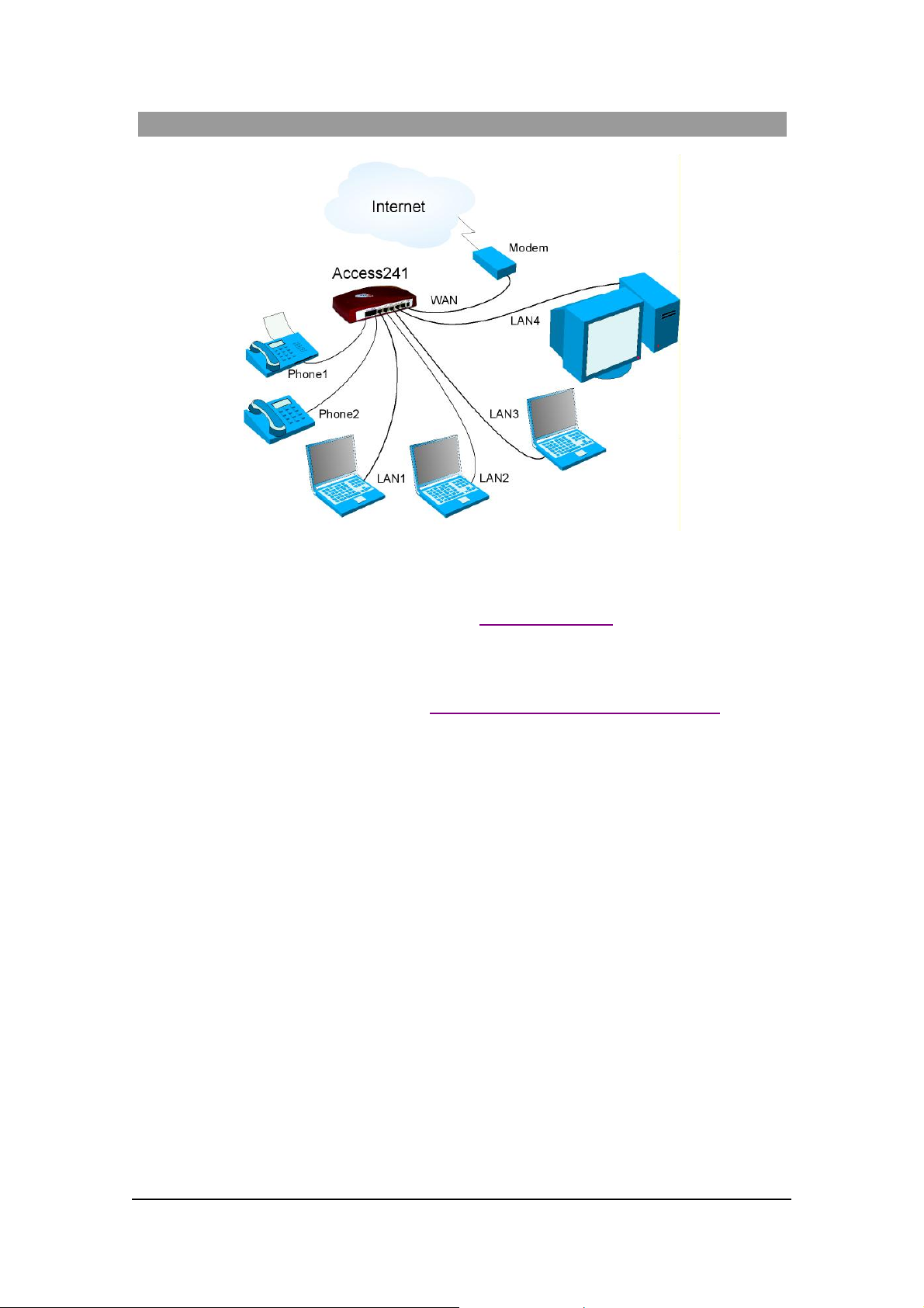
F i gu r e 4: Access 211/ Acces s 211N H ome N etw ork Ins tall a tion
1. Unpack the Gateway.
2. Verify you have the components listed in the Required Equipme nt
3. Place the Gat eway on a desktop or other level surface, or mo unt it on a wall. Choose a
l ocation that i s near the d evic es to b e connected and close to a wall socket.
4. Connect the W AN port on the Gateway’s rear panel to the Ethernet socket on your
br oadband modem with an Ethernet 10/ 100BaseTX (RJ-4 5) cable.
5. Connect th e LAN port on t he Ga teway’s rear panel to an open Et hern et LA N port on your
r o ute r o r s wit ch u si n g t h e s upp l ie d Et h er net 1 0/100Ba s eT X ( RJ -4 5) ca bl e , in ac co r dan ce
with the instructi ons pr ovided w ith your rou ter or swi tch.
6. Connect t he phones to the Phone1 and Phone 2 s ockets on the G ateway rear pane l wi th RJ-11
Phone cables. Up to five phones in para llel may be connected to each port. (If your provider
enabl es onl y one phone li ne, use the Phone 1 port).
li st above.
7. Veri f y t h at all system co mp onent s are p r operly installe d. Secur e al l cable connect ors in t he
appropriate ports .
8. Connec t the power ad a pter to the pow e r c o nnecto r of the G atew a y and to a wall socke t.
9. Check that the Power LED on the G ateway front panel glows steadily.
23
MN100129 Rev E

ACCES S 241-FXO/ 241/ 211/ 211N VOIP GATEWAY USER GUIDE
If yo u are usin g a DSL modem, y ou will need t o enable PPPoE a s described in sect ion
“Enablin g Point-to-Point P roto co l over Ethern et (PPPoE)”
, and disable PPPoE on your
router.
10 For Access 211 - Wait for the Voi ce LED to glow, i ndicating that you are connec ted to your
VoIP service providers . It may take a minute or tw o for these connections to b e established.
For Access 211N – Wait for the respect ive Phone (Voi ce) LE D (L ED Phon e1 for P H1
port/L ED Phone2 for PH2 port) on the Gateway front panel to glow, indicati ng connecti on to
your Internet and VoIP providers. It may take a minute or t wo for these connect ions to be
established.
1 1. Res et yo ur ro ute r an d v er ify that yo ur br oadba nd mo dem an d yo ur r o ut er ar e workin g.
Verify that your broadband Internet s ervice functions properl y.
12. Pick up the phone on each li ne to verify that you c an hear the dial tone .
24
MN100129 Rev E

ACCES S 241-FXO/ 241/ 211/ 211N VOIP GATEWAY USER GUIDE
Wall -Mou ntin g th e G ate way Unit
I n order to mo unt t h e un it o n th e wal l, use t wo woo d sc re ws 6 .1 ” (15 .5 cm) ap art for hor izont a l
posit ioning or 2.68” (6.8 cm) apart for vertical positioning. Use screws as specified below. Holes
for mounting on the wall a re situ a ted a t the b o ttom of the unit, as show n in the follow ing figu re.
Distance for verti cal hanging
= 2.68” ( 6.8 cm )
Distance for horizontal
Clasp for fastening DC
power-feed cab le
Distance for horizontal
hanging = 6.1” ( 15. 5 cm)
hanging = 6.1” ( 15. 5 cm)
Mounting Screws Maximum Dimensions
H ead dia m et er ( H):
Shank diameter (S ):
Length (L):
Max 9 m m (0. 3 5" )
Ma x 3. 5 mm (0.138")
25 - 30 mm ( 1 " - 1 .2" )
H
NOTE The Access 211N is usually situated on the desk top.
S
L
25
MN100129 Rev E

ACCES S 241-FXO/ 241/ 211/ 211N VOIP GATEWAY USER GUIDE
Using the Ga tew ay
Placing a telephone call with the Gateway is the same as using a telephone with a standard
telephone provider.
First Call
If you ha v e two lines, y ou can place the fi rs t c all fr o m o ne ph one l i ne to the s ec ond p hone line on
your Gateway. This step ensures that the Gat e way is operating properly and that a ll configuration
infor ma ti o n is c orrec t.
PST N Port Calling with Access 241-FXO
PSTN Outgoing Calls
• Check with your VoIP prov ider wh ich numbers are dialed t hrough the PSTN port.
• P STN o ut goin g calls can be dialed fro m telephones connected to the Phone1 or Phone2
port s (even though Phone2 might not have a dial tone if the port was not enabled by your
provider).
PSTN Incoming Calls
• An incoming PSTN ca ll is always receive d on the Phone1 p ort.
• Call Wait ing is act ivated if Phone1 is engaged in a VoIP ca ll.
PSTN Call Behavior during Unit Power-down or Inactive VoIP Service (Voice LED is
off)
• The phone connec ted to the Ph one 1 port will opera te as a PS TN phone . Only r egu lar
public t e le phone service is available.
L ife Line Port Calling with Access 241 and Access 211
Life-line Port Calls during Unit Power-down or Inactive VoIP Service (Voice LE D is
off)
• The phone connec ted to the Ph one 1 port will opera te as a PS TN phone . Only r egu lar
public t e le phone service is available.
Advanced Calling Features for S IP
In the following subsect ions:
• An exp ressi on such as “dia l flash + 7” i mplie s “press on fl a sh, then press on 7” (the
diali ng sequence progresses a s re ad from l eft to ri ght ).
• The St ar (o r Asterisk) key is represented by the symbo l “
• The term destination number within an expression implie s “dial th e destin ation number”.
”.
*
The follo wing features are only available for the VoIP calls and not for the P STN calls un less
otherwise stated.
26
MN100129 Rev E

ACCES S 241-FXO/ 241/ 211/ 211N VOIP GATEWAY USER GUIDE
Call Waiting
I f you a re enga ged in a VoIP call and a third party calls your li ne, you hear a s hort ton e on your
line. The calle r hears a normal ri ng tone.
For Access 2 41-FXO, the Call Waiting tone will also be heard if you re ceiv e a PS TN ca ll while
yo u are engaged in a VoIP call on the Phone1 port . Pr ess flash to tog gle be tw ee n calls.
Caller ID Display, Cal ler Identity on Call Waiting
The Gateway display s the Caller ID of the current caller and the Caller ID of a thir d party calling
during a conversation.
Conference Call
To establish a Conference Call, call th e f irst number, dial flash to hold th e call, dial the se cond
num ber an d befor e or aft er bein g answered, di al flash once more to es tablish the 3-w ay cal l.
Call Forwarding
To set the Forward option, dial * + 2 + destin ation numb er.
All calls to the phone w ith Forward set will be received at the destination num ber.
To unset the Forward opti on, dial * + 3.
Condi tional Call F o rwa rdi ng
To act ivate Cond itio nal Call Fo rw ard ing , dial * + 1 + destina tion numb e r. If the call has been
m ade an d the phone h as not been p ick ed up with in 2 0 se con ds, th e ca ll i s forwar de d to th e
des t inat ion number . T o cance l Ca ll Forwarding, dia l * + 3.
Attended Transfer Call
T o pe rfo rm an A tte nde d Tr an s fer C all (the f irst ca llee is part of the transfe r until a new c a llee
answers) , dial flash to ho ld the call, di al th e new nu mber and wait to hear the ring. When the phone
rings or after the new callee answers, put the handset down.
Before the new callee picks up the handset the phone will ring both at the destination number and at
your li n e .
By picking up the han dset, the callee at the destination num ber will be engaged in the c a ll with the
orig in al cal l er .
I f t he ca ll ee at t h e de st in ation n um ber do e s n ot p i ck up t h e han d set , you can r ec ei ve t h e c a ll b y
picki ng up t h e ha nds et as long a s t h e pho n e ring s .
Blind Transfer Call
T o pe rfo rm a Bli nd Tr ansfe r (a new call is automat ically set bet ween t he caller and th e second
callee an d the first callee is immediat ely removed from the call) when a call is received dial *98 and
then the dest inat ion number. The phone will r ing at the destination number an d the first callee will
have a dial tone.
Hold
To ho ld a call that you are rec eivi ng , p ress flash once. The ca ller will be on hold. To retr ieve the
call , pr ess flash once more.
27
MN100129 Rev E

ACCES S 241-FXO/ 241/ 211/ 211N VOIP GATEWAY USER GUIDE
When the call er is on hold, you c an ru n a nother call b y dialing another number. When you pu t the
handset down t he phone will r ing. Pick up the call an d yo u will be engaged in a call with the
original c a ller. If you wish yo u can then transfer the call as de scribed above
, or just proceed wit h
the original call.
Do Not Disturb (DND)
To act ivate DND, d ial * 4. The caller wil l hear th e "busy " tone. To cancel DND , dial *5
Redi aling of Last Received Call
To dial the last received call, dial *69.
Block Last Received Caller
To block the last received caller, dial *60. To start acceptin g calls from the blocked num ber again,
dial *80, or dia l *60 to accept the previousl y blocked numbe r a nd block the latest received caller.
Auto Redial
When a number is dialed and the dialed num ber is busy, the Caller can activate Auto Redial by
hangi ng u p, d iali ng *66 and la yi ng the ha ndse t d own ag ain . The G a tew a y w ill per iodi call y dial the
busy nu mber for a default period of 30 mi nu tes. When the dialed number is reac hed the Call er will
be notifie d with a special dist inct ive ring. By picking up the phone, the ca ller will be immediately
in the cal l .
I f the called party ha ngs up and t he caller does not pick up the phone when the spec ial ring t one is
hea rd, th e n on the ne x t a ttem pt to u se the phone the Calle r w ill g e t a bu sy signal i ndica ting th a t the
Auto Redial service succeeded. To place the next call, th e caller needs to han g up and pick up the
phon e a gain.
To cancel the periodic Auto Redialing before the timeo ut has been reached, dial *86.
B lock Call er ID
To blo ck sendi ng your Calle r ID before diali ng, dial *70 a nd then the requi red telephone numb er.
Anonymous Call Rejection
To reject anonymous calls, di al *77.
To accept anonymous ca lls dial *78.
Advanced Calling Features for H.323
In the following subsect ions:
• An exp ressi on such as “dia l flash + 7” i mplie s “press on fl a sh, then press on 7” (the
diali ng sequence progresses a s re ad from l eft to ri ght ).
• The St ar (o r Asterisk) key is represented by the symbo l “
”.
*
• The term destination number within an expression implie s “dial th e destin ation number”.
Call Waiting
I f you a re engaged i n a call and another pa rt y calls your lin e, yo u hear a s hort tone on your line.
The caller h ea rs a ri nging ton e.
28
MN100129 Rev E

ACCES S 241-FXO/ 241/ 211/ 211N VOIP GATEWAY USER GUIDE
To accept the new call, dial fla sh + *. To r e tu rn to the o rigi n call, dial flas h + * again.
Conference Call
I f you are enga ged in a ca ll an d wis h to add a thir d party, dial flash + 7 , then dial th e third par ty’s
number. Once the thir d party answers the call, a 3-way call is establish e d.
To drop the conference, dial fla sh + 8.
Call Forwarding
To set the Forward option, dial * + 2 + destin ation numb er.
All calls to the phone w ith Forward set will be received at the destination num ber.
To unset the Forward opti on, dial * + 3.
Transf erri ng a Call
To tra ns f er a cal l tha t you are receiving to an other numb e r, d ial flash + 4 + destination number and
put t h e hand s et d own.
The phone will ring both at the destin ation number and at your line.
By picking up the han dset, the callee at the destination num ber will be engaged in the c a ll with the
original call er. Your phone will s top ringi ng.
I f t he ca ll ee at t h e de st in ation n um ber do e s n ot p i ck up t h e han d set , you can r ec ei ve t h e c a ll b y
picki ng up t h e ha nds et as long a s t h e pho n e ring s .
Hold
To h old a c all that you are receiving, press fl a s h + 1. Th e caller will be at hold.
You c an then run a noth er ca ll by dialin g another number. When you put the handset down the
phone will rin g. Pick up the ca ll and you will be engaged in a call with the origina l caller. If you
w is h you ca n th e n tra nsf er the ca l l as described abov e, or just pro ceed wi th the orig inal ca l l.
Advanced Calling Features for MGCP
Ad vanc ed calling fea tu res ar e suppo r ted . R e fe r to you r C all Age n t for th e ad va nced call i ng fea tures
supported.
29
MN100129 Rev E

ACCES S 241-FXO/ 241/ 211/ 211N VOIP GATEWAY USER GUIDE
Advanc ed C onfi gura tion via the W eb
If you need to change the default configur ation of your Gat eway, proceed as follo ws.
• Connect a P C to one of LAN ports on the rear panel of the unit.
• Open the Web browser on the PC.
• I n th e Web br owser' s addr ess field, type 192.16 8.100.1 (t he defa ult LAN IP addre s s of
the unit) t o open t he hom e pa ge of the un it.
• To update a setting, pro ceed as described in the follo wing sections. Enter t h e required
se ttings on t he a pprop riat e We b pages and then save the changes by click ing on th e Save
button at the bottom of each page.
• On ce a ll settings have been save d, select the Reset option on the left-hand side of the
Web page t o re s et the VoIP Gate wa y and eff ec t uate the new set t ings.
WA N Configuration
To c hang e the WA N m ode from DHC P de fault config ura tion to fixed I P config ura tion , or to
assi gn a differe n t fixed IP addre s s , perform as fol lows:
1 . Co nf igure the P C to dy nami cally ac quir e an IP addres s (D HCP) or s et it t o a fi xed IP
addre s s in t he subnet 192.168.100.xxx.
2. Enter th e IP address of the unit into t he PC W eb br owser. (T he default LAN IP address is
192.168.100.1). The Access VoIP Ga tew ay home page a ppears (Figure 5).
F i gu r e 5: Exampl e Acces s V o I P Ga t ewa y H ome P age
4. In the vertical menu bar on the left, select WAN.
30
MN100129 Rev E

ACCES S 241-FXO/ 241/ 211/ 211N VOIP GATEWAY USER GUIDE
The WAN St a tu s pa g e a p pears :
Figure 6: WAN Status Page
5 . T o ch an g e n et wo rk an d Vo IP IP s ett in gs , se l ect WAN Settings on th e horizontal menu bar.
The WAN Co nf igu rat ion page appears (Figure 7).
31
MN100129 Rev E

ACCES S 241-FXO/ 241/ 211/ 211N VOIP GATEWAY USER GUIDE
Figure 7: WAN C onfiguration Page
6. Sele ct eith er of the following options.
To dynamically obtain a WAN IP address:
• Select Obta in W AN configuration dynamically.
R
O
To spec if y f ix ed va lues f or th e WAN IP addr es s, ma s k, g ateway, DN S Serv er, etc :
• Select Sp ecify f ixed WAN Conf ig ur ation
• Th e following fields, assoc iat ed with fixed IP addre ssing should be filled in or
chan ged only if your br oadband prov ider requi re s th em. Use th e value s s upplied by
yo ur broadband p rovider :
IP Address , IP Net mask, IP Gateway, IP DNS Serv er 1 and 2, Ho st N a m e and
Do main Name.
8. Mu lti cast Rates – L imit s f or Multicast an d broadcast traffic, as p ercentage of Eth ernet bit-
rate tra ffic:
• Broad cast Rate
• Multicast Rate
32
MN100129 Rev E

ACCES S 241-FXO/ 241/ 211/ 211N VOIP GATEWAY USER GUIDE
9. S croll down to the b o ttom of the Web page , and cli ck Save WAN Set ting s.
10. Select Reset in the vertical menu bar, to reset the Gateway (see sect ion “ Completing the
Gateway Configurat ion”.).
E nabling P oint-to-P oint P rotocol over Ethernet (PP PoE)
If you have a DS L modem and are NOT using a router between the Gateway and the
modem, configure PP PoE as follows:
1. In the horiz ontal menu bar of the WAN page , select PPPoE .
The WAN PPPoE C onfig u ration page appears (Figure 8).
Fi gure 8: WAN PPPoE C onfig uration Page
2. Select Yes in th e Enable PPPoE drop-down list box.
3. Fill in the username and passwo rd in the Authentication fi elds as supp lied by yo ur DSL
provider. Opt ionally you c an enter the service n am e for th e request ed service. To select a
specifi c provide r , e n ter his access name in the AC na me fi eld . Clic k Sa ve PPPoE Se t tings.
4. Select Reset in the ve rtical menu bar, to reset the unit ( see “Comp leting the Gat eway
33
MN100129 Rev E

ACCES S 241-FXO/ 241/ 211/ 211N VOIP GATEWAY USER GUIDE
Configurati on” on page 46).
Enabling Point-to-Point T Protocol (PPTP)
If you need a PPTP co nnec tio n conf igur e PPT P as f ollow s:
1. In the horizonta l menu ba r of the WAN pag e, select PPTP.
The WAN PPTP Configuration page appears (Figure 9).
Fi gure 9: WAN PPTP Con figuration Pag e
2. Select Yes in th e En able PP TP dro p-down list box.
3. Fill in the username and password in the A uthentication fields as supp lied by your
provider.
4. E nter the Server Address in the text box . Click Save PPT P Sett ings.
4. Select Reset in the vertical menu bar, to reset the unit (see section “Completing the
Gateway Configurat ion” on page 46).
MAC S poofi ng
MAC spoofing may be required in cases that your broadband provider associates a p art icular
serv ice to a specific devi ce (e.g. your computer ).
34
MN100129 Rev E

ACCES S 241-FXO/ 241/ 211/ 211N VOIP GATEWAY USER GUIDE
To override the MAC address of the de vi ce that you supplied to you r broadband pro vider
1. In the horiz ontal me nu ba r of the WAN page, sele ct MA C Spoofing.
The MA C Spo ofi ng Con f igur at io n page appears (Figure 10).
Figure 10: MAC Spoofing Configu ration Page
2 a. I f yo u kno w th e M AC a ddress of yo ur dev ic e, ent er it int o th e W AN MAC Addr ess
(Sp oofed) field an d click Save M A C Sp oofing Settings.
2b. If yo u do not know th e MAC a ddre s s of your device, c opy t he v alue f rom the Le arnt
MAC’s field to the WAN MAC Address field, click Sav e MAC Spo ofing Set t ings and
click Reset to rese t the Ga tew ay .
LAN C onfiguration
• T he LAN Configura tion Web pages allo w you to co nfi gure th e foll owing LAN s ett ings:
L AN IP addr ess an d s ubnet ma s k;
• LAN broadcast and m ulticast traffic limit ation;
• Rat e cont rol;
• DHCP Serv er settings;
• P ort forwarding – to enable access to lo cal ports fr om an external net work;
• Enable/disable NAT IPSec Tr averse
To o pen the LAN Configuration pages:
In the vertical menu bar on the left of the Access VoIP Gateway Web p age, select LAN.
The LA N Co nf ig ur a t io n page appears (Figur e 11).
35
MN100129 Rev E

ACCES S 241-FXO/ 241/ 211/ 211N VOIP GATEWAY USER GUIDE
Figure 11: LA N C onfiguration Page
Configuring LAN Settings
T o conf igur e LAN sett ings, br o adcas t and multic a st t r aff ic limits and /o r rate c o ntro l, pr oceed
as fo llows:
1. In the L AN Configur atio n page, enter the LAN IP address and subnet mask.
2. O ptionally, set the broadcast and multic a st limits in the approp riate fields.
3. Selec t o ne o f the foll owing Rate Control options:
• D isable Rate L imi ts (this is the def ault setting)
O
R
• Dy namic Rate Limits
O
R
• Fixe d Rate Limits
Wi th the R a te c ontr ol fea tu re y ou can l im it the b a nd w id th alloca ted to the de vi ce(s) co nne cted
36
MN100129 Rev E

ACCES S 241-FXO/ 241/ 211/ 211N VOIP GATEWAY USER GUIDE
to the LAN port. This is espe cially important for broa dband use rs whe re the uploa d link to the
ISP is considerably lower than the download link from the ISP. Setting the Rate control
parameters will insure th at vo ice quality is preserv ed even while r unnin g heavy bandwidth
applica ti ons o n th e d e vi ces c onne cted to LAN po r t.
Select Fix e d Rate Limi ts to limit the bandwidth r eceived from the LA N to the value of the
LAN R a te Li mit tha t is s pecifi ed in the te x t b ox (in Kbps). I f you c hange this value, th e actu al
rate limit will be rounded to the n ea res t mul tip le of 32 Kbps .
I f you want to select t he Dynamic Rate Limit opt ion you must first set the User Upload Rate
para me t er to the valu e of the use r’s a vailab le upload bandw i dth o n the WA N con nectio n. The
Access gateway will dynamically reserve bandwidth for the active calls and limit the
ban dwidt h fo r th e LAN dev ic e to th e remai nin g ava ilabl e ban dwidt h. By def ault th e User
Upl oad Ra te i s set to 32 K bp s, ho wev er, y o u may ch oo se v al ues fro m 12 t o 1 3104 0 Kbp s.
You can view the act ual bandwidth allocat ed t o the LAN device in the Current LAN Rate
Limit parameter.
4 Click Save LAN Settings.
DHCP Server Config uration
To use a DHCP Server to automatically assign IP a d d resses and subnet masks to devices
co nne c ted to the LAN port, proceed a s follows:
1. I n the horizontal men u bar o n th e LA N page, select DHCP.
The DH CP S erver Co nf ig ura t io n page appe ars (Figure 12).
37
MN100129 Rev E

ACCES S 241-FXO/ 241/ 211/ 211N VOIP GATEWAY USER GUIDE
Figure 12: DHC P Server Con figurat ion Page
2. To enable the DHCP Se r ver, s elect the Server Setting s Enab led option.
3. For Scan n etwork for given lease s upon reboot, the Yes opt io n shoul d be s el ecte d in
order to prevent the need to reset all d evices that are connected to the network on reboot.
4. Fill i n the follow ing field s:
• Client IP Address range – up to 24 IP addre s s es a re allo we d. To change the
LAN IP, see “Configuring LAN Settings
” on page 36.
• Do main Name – optionally enter the domain name for the local LAN.
• DNS Serv er 1 and 2 – if left blank, the DNS Server IP a ddresses will be
acquired from the WAN connection. If you w ant to use different DNS S erver
addresses, en ter t h eir IPs here. These addresses will appear at the top of the
computer’s DNS Servers list.
• Default Lease Time – the default value is 86400 seconds (24 hours). The
38
MN100129 Rev E

ACCES S 241-FXO/ 241/ 211/ 211N VOIP GATEWAY USER GUIDE
available time range is from 30 seconds to 30 days.
• Static Address Assignments - you can define LAN devices manually. T he
devi ce s ca n be defined by Host na me or by MA C address :
Identify Using – Select the type of identifier, Host name or MAC, you wish
t o use in the next f ield.
Host Ide n tifie r – Enter the appropriate value (Host name or MAC).
In terna l A ddres s – stat ic I P of the local hos t .
5. To view the DHC P Client table (Figure 13), click on View DH CP T ab le.
Figure 13: DHC P Client Tabl e Page
Port Forwarding
Port for warding asso ciat es local port ranges to local IP addresses. This en ables external net work
users to access local devices, wit hout the need for the lo cal servers to first access the global
network.
To co nfigu re port fo rwarding:
1. In the horizonta l menu ba r of the LAN pa g e, sele c t Port Forwarding.
The Port Forwarding Con figuration page appears (Figure 14).
39
MN100129 Rev E

ACCES S 241-FXO/ 241/ 211/ 211N VOIP GATEWAY USER GUIDE
Figure 14: Port Forwarding Confi guration Page
2. Enter an allo wed port range ( do not use any of the port numbers that are specif ied in the
Reserved Ports list), and specify th e low byte number of the destination address in decima l
notation.
3. Click on Add.
4. Repeat for additional port forwarding associations as required. Up to 10 devices can be
defined.
5. Click Sav e NA PT Set ting s.
Enabling the Network Address Translator (NAT)
The IPSec NAT Traverse featu re supports IPS ec VPN passing through NAT.
NOTE
Users with NAT -T (UDP tun nel fo r VPN traffic) should not enable th is feat ure. T his
optio n i s disabled by def ault.
The objectiv e of th e Network Addr ess Tra nsl a tor, NA T, is to pr o vide func tionali ty as i f the priv a te
net work had gl obally unique addr esses an d the NAT dev ice was not pr esent. B asic N AT allo ws a
one-to-one mapping bet ween one private address and one public address. In its simplest
40
MN100129 Rev E

ACCES S 241-FXO/ 241/ 211/ 211N VOIP GATEWAY USER GUIDE
con figur at ion, t he NAT op er at es on a ro ut er conn ecti ng two net wo rks to gether. On e of t he se
networks (designated as inside) is addressed with either p r ivate or obsolete addresses t hat need to
be converted into legal addr esses before packets are forwar ded onto th e ot her networ k (designated
as outside). The translation operates in conjunction with routing, so that NAT can simply be
enabl ed o n a custo me r-sid e Int er n e t acces s r ou ter w he n trans l a tio n is d esired.
NAPT (Network Port Address Translator) maps a single public address to one or many internal
addre s s es and all network IP addr esse s on the connect ed comp uters are lo ca l and can not be seen by
the ou tside w orld .
NAT with Po rt Address Translation (NAPT) is an extension to NAT in that NAPT uses T CP/UDP
ports in addi tion t o netw ork addresses (IP addresses ) to map ma ny priva te ne twork addresses to a
single outside a ddress.
To enable the Network Add re s s Trans lato r:
1. In the horizontal menu bar of the LAN page, select NAT. The NAT IPSec traverse
configuration page appears (Figur e 15).
Figu re 15: NAT IPSec Traverse Configuration Page
2. Check in the Enable NA T IPSec trave rse check box.
3. Click Save Settings.
41
MN100129 Rev E

ACCES S 241-FXO/ 241/ 211/ 211N VOIP GATEWAY USER GUIDE
S ecuri ty C onfi guration
The Security Configuration Web page allows you to configure your User Passw ord.
• Maximum length of password is up to 20 characters.
• You can use any character to build your password.
To con f ig ur e a n ew Us er P a ssw ord :
1. In the v ertica l menu ba r of the current Gateway Web page, select Se curity.
2. In the N ew Password text box, ty pe in your User Password. Yo u may use any cha racter to
form your password. The passw ord must be no longer then 20 characters.
Figure 16: User Password Con figurat ion Page
3. Re-e nter the password in the Confirm ne w password tex t box.
4. Click Sav e P as sw ord. Th e f ol low i ng w ind ow a p pe ars :
42
MN100129 Rev E

ACCES S 241-FXO/ 241/ 211/ 211N VOIP GATEWAY USER GUIDE
Figure 17: Password Protection Page
4. En t er your Us e r Pas s wor d .
5. Click Authenticate. The application home page o pens.
Once you have created a password, the Gateway’s Web management system will logout
auto matical ly af te r 10 minutes . I t is re com mended to Logout aft er co nfigur at ion.
Line Configuration
The Line C onfiguration Web pages, Li n e 1 , Li n e 2 and Line3, allo w yo u to configure the Call
For war ding settings and volume (Ga in) sett ings.
Call Forward Line Configuration
The foll owing Call Forwa r d settings are av ailable for Line 1 and Line 2 :
• Disabled
• Unconditional
The call is always diverted to another destinat ion.
• Conditional
Ca l l ee s fr e quen t ly wi sh t o r e dir e ct in co m in g ca ll s t o an alt ern ativ e de st in at io n i f t h e pr im ar y
destinat ion fails to answer within 20 seconds. The reasons for failure in clude busy callee,
callee’ s phone is disconnected, cal lee does not answer, or callee deny ing the incoming call. T he
alt ernat ive destination is t yp ically a voicemail sy st em but it may also be another human or
some other SIP device.
The Forwarding settings c an be se lected for each line separately.
Gain Control Configuration (Volume)
Th e f o llowin g Gain Control Configurat ion s e ttings for (V oIP ) i nter net tele phone c ommu nication
are avai lable fo r Line 1 and Line 2 (FXS):
• The Line (input) Gain range is <+12 to -12>. This sets the volume at which the callee
hea rs you .
• The Headset (output) Gain range is <+12 to -12>. This set s the volume at which you
he ar th rough th e headset . If this volume is too high, there is an echo in the he a dset.
43
MN100129 Rev E

ACCES S 241-FXO/ 241/ 211/ 211N VOIP GATEWAY USER GUIDE
T he f o ll o win g Gain Control Configurati on set t in gs f o r P ST N com m un icat ion ar e av a ila bl e fo r
Line 3 (FXO):
• The Line (input) Gain range is <+12 to -12>. This sets the volume at which the callee
hea rs you .
• The Headset (output) Gain range is <+12 to -12>. This set s the volume at which you
he ar th rough th e headset . If this volume is too high, there is an echo in the he a dset.
To c onfigure settings for Li ne 1:
1. In the v ertica l menu ba r of the current Gateway Web page, select Line.
2. In the horizonta l menu ba r of the Line page, select Line 1.
3. In the Call Forward Line Configuration field, select the desired option.
4. In t he Gai n Contro l Con fi guration, Line (input) Gain field, select th e re qui red volume.
5. In the Gain Control Configuration , He adset (output ) Ga in f ie ld, select the re quired volum e.
6. Click Save Line Settings.
Figure 18: E xample for S ett ing Call F orwarding for Line 1
44
MN100129 Rev E

ACCES S 241-FXO/ 241/ 211/ 211N VOIP GATEWAY USER GUIDE
To c onfigure settings for Li ne 2:
1. In t he horizonta l menu bar of t he Line page, select Line 2 .
2. In the C all Forwa r d Line Confi guration f i eld, sele ct th e de s i re d opt ion.
4. In t he Gai n Contro l Con fi guration, Line (input) Gain field, select th e re qui red volume.
5. In the Gain Control Configuration , He adset (output ) Ga in f ie ld, select the re quired volum e.
6. Click Save Line Settings.
To c onfigure settings for Li ne 3:
1. In t he Gai n Contro l Con fi guration, Line (input) Gain field, select th e re qui red volume.
2. In the Gain Control Configuration , He adset (output ) Ga in f ie ld, select the re quired volum e.
3. Click Save Line Settings.
NOTE After e nte r ing and sav i ng all configurati ons, you M US T reset the G ateway.
45
MN100129 Rev E

ACCES S 241-FXO/ 241/ 211/ 211N VOIP GATEWAY USER GUIDE
Compl eti ng the Gatew ay C onfi gurati on
After entering and saving all configurations, you must reset the Gateway.
T o reset the Gateway:
1. I n the vertical menu bar of the current page, select Reset.
The Reset page (Figure 19) appears.
2. Click the Reset button . T h e Gat e wa y reboot s an d t he ap plic ation hom e page op ens with t h e
new configuration settings.
Figure 19: R eset Page
46
MN100129 Rev E

ACCES S 241-FXO/ 241/ 211/ 211N VOIP GATEWAY USER GUIDE
T roubles hoot ing
Problem Solution
The unit does not function.
The Power LED is off.
Che ck t h at t h e A C/ D C a dap t er i s p r op er ly c onn ect e d, an d th at
pow e r is suppl ied to the wall pow e r ou tle t.
No dial tone (a ) V erify that the phone line is secu rely plugged into the Phone1
or Phone2 po r ts.
(b) Verify that the WAN LED on is lit. If it is not, check that the
WAN cable i s p ro perly connect ed.
(c) If there is still no dial tone, check with your VoIP and
br oadband service provi ders.
T he In te rn et serv i ce doe s not
work properly (single PC
(a ) V erify th at the WA N and the LA N LEDs are li t . If n o t , v erify
that the Ethe rnet cables are properly connected.
connection, wit hout a rout er) .
(b) Connect your PC direc tly to the broadband modem and check
the Inte rnet serv ice.
If the Internet service functions properly when the Gateway is not
connected, review the LAN settings according to the LAN
co nfig u r a tion i nstru cti o ns abov e.
T he In te rn et serv i ce doe s not
wor k p rop erl y (loca l net work
connected through a router).
Follow the inst ructions supplied with your router.
47
MN100129 Rev E

ACCES S 241-FXO/ 241/ 211/ 211N VOIP GATEWAY USER GUIDE
Specif ic atio ns
Dimensions Access 241-FXO/241/211
4 .75”(W) x 7.36”(L) x 1.77”(H)
120(W) x 187(L) x 45(H) mm
Access 21 1N
3 .55”(W) x 3.55”(L) x 0.95”(H)
90(W) x 90(L) x 24(H) mm
Weight: Access 241-FXO/241/211
1.3 2 l bs (0.6 kg)
Access 21 1N
0.6 6 l bs (0.3 kg)
Operating temperature:
Humidity:
Pow er so u rce:
Emission a nd safety r egulations :
0°C - 45°C (32°F - 113°C)
10% - 90% no n- c on densi ng
5 VDC@2 A – External power supply (Access
211/211N and Access 241)
5 VDC@2.6 A – External power supply (Access 241FXO)
FCC Class B, UL, CUL , CE
48
MN100129 Rev E
 Loading...