

Telco Systems 2643-1E, 2643-15-01, 2643-14-01, 2643-17-01, 2643-1J-01 Installation & User Manual
...Page 1
Metrobility® 10/100 AutoTwister
®
Installation & User Guide
Models: 2643-13-01 / 2643-14-01 / 2643-15-01 / 2643-16-01 /
2643-17-01 / 2643-1E / 2643-1G-01 / 2643-1J-01 /
2643-1K-01 / 2643-1M-01 / 2643-1X-01 / 2643-1Y-01
Page 2

The Metrobility® 10/100 AutoTwister
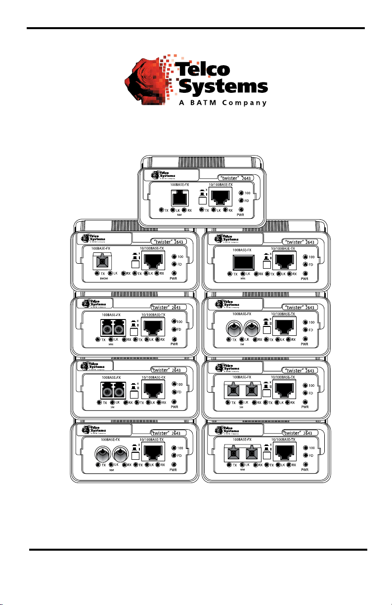
2643-13-01 _____10/100Base-TX to 100Base-FX multimode SC
2643-14-01 _____10/100Base-TX to 100Base-FX singlemode SC
2643-15-01 _____10/100Base-TX to 100Base-FX multimode ST
2643-16-01 _____10/100Base-TX to 100Base-FX singlemode ST
2643-17-01 _____10/100Base-TX to 100Base-FX singlemode SC (40km)
2643-1E-01 ____10/100Base-TX to 100Base-FX multimode MT-RJ
2643-1G-01 ____10/100Base-TX to 100Base-FX multimode VF-45
2643-1J-01 ____10/100Base-TX to 100Base-FX singlemode SC (100km)
2643-1K-01 ____10/100Base-TX to 100Base-FX multimode LC
2643-1M-01 ____10/100Base-TX to 100Base-FX singlemode LC
2643-1X-01 ____10/100Base-TX to 100Base-FX singlemode 1550/1310nm
bidirectional wavelength division multiplexed (BWDM) SC
2643-1Y-01 ____10/100Base-TX to 100Base-FX singlemode 1310/1550nm
BWDM SC
This publication is protected by the copyright laws of the United States and other countries, with all rights reserved. No
part of this publication may be reproduced, stored in a retrieval system, translated, transcribed, or transmitted, in any
form, or by any means manual, electric, electronic, electromagnetic, mechanical, chemical, optical or otherwise, without
prior explicit written permission of Telco Systems, Inc.
© 2009 Telco Systems, Inc. All rights reserved. Printed in USA.
Page 3

Table of Contents
10/100 AutoTwister Installation & User Guide
Overview ....................................................................................................................4
Installation Guide ....................................................................................................5
STEP 1: Unpack the AutoTwister and Accessories ....................................5
STEP 2: Choose an Appropriate Location .................................................5
STEP 3: Set the Switches ............................................................................5
STEP 4: Connect to the Network ................................................................9
STEP 5: Apply Power ..............................................................................11
User Guide ...............................................................................................................13
LED Indicators ..........................................................................................13
Factory Settings ........................................................................................14
Link Loss Return (LLR) ...........................................................................15
Link Loss Carry Forward (LLCF) ............................................................16
Auto-Recovery ..........................................................................................17
Auto-Recovery Application Example .......................................................18
Topology Solutions ...................................................................................19
Technical Specications ...........................................................................20
Product Safety, EMC and Compliance Statements ...................................22
Warranty and Servicing ............................................................................23
Metrobility, Metrobility Optical Systems, NetBeacon, AutoTwister and “twister” are registered trademarks of Telco
Systems, Inc., a BATM company.
The information contained in this document is assumed to be correct and current. The manufacturer is not responsible for
errors or omissions and reserves the right to change specications at any time without notice.
Page 4

Overview
The Metrobility 10/100 AutoTwister provides seamless migration between
Ethernet and Fast Ethernet networks, in addition to built-in media conversion
allowing high-speed integration of ber optic and twisted-pair segments. A complete
set of LEDs allows for quick status verication, and a bank of DIP switches provides
added versatility on each port. To optimize your Ethernet network, each port operates
independently in either half or full duplex.
The 10/100 AutoTwister standalone units offer the following key features:
• Auto-negotiation switch on the twisted-pair interface.
• Half to full duplex conversion.
• Link loss auto-recovery on the ber optic port.
• Link Loss Return (LLR) functionality to aid in troubleshooting a remote
network connection on the ber optic port.
• Link Loss Carry Forward (LLCF) functionality to aid in troubleshooting a
remote network connection.
• An MDI-II to MDI-X switch that eliminates the need for crossover cables
on the twisted-pair port.
• Full-duplex ow control on each port.
• Store-and-forward switching to improve overall network performance by
buffering packets during times of heavy congestion and to prevent the forwarding of corrupted packets.
• High-performance switching engine that performs forwarding and ltering
at full wire speed (148,800 packets per second).
• The ability to learn up to 1,024 MAC addresses.
• Low last-bit-in to rst-bit-out delay.
• VLAN tagging support.
• Discards short packets (less than 64 bytes) and packets with CRC or align-
ment errors.
• Maximum transmission unit (MTU) size of 1522 bytes.
• 128K bytes of buffer memory.
• Full compliance with applicable sections of IEEE 802.3, IEEE 802.3u, and
IEEE 802.3x.
4
Page 5

Installation Guide
Follow the simple steps outlined in this section of the guide to install and start
using the Metrobility 10/100 AutoTwister.
Unpack the AutoTwister and Accessories
Check that the following components have been included:
1
• 10/100 AutoTwister
• Power supply
• Power cord
• Four (4) rubber feet
Your order has been provided with the safest possible packaging, but shipping damage does occasionally occur. Inspect your order carefully. If you
discover any shipping damage, notify your carrier and follow their instructions for damage and claims. Save the original shipping carton if return or
storage of the unit is necessary.
Choose an Appropriate Location
The 10/100 AutoTwister is intended for use in either ofce or industrial
2
environments. The unit must be located within six (6) feet of the AC power
source being used and placed as far away as possible from electrical noise
generating equipment such as copiers, electrostatic printers and other motorized equipment. If exposed twisted-pair wiring is used nearby, the wiring
should be routed as far away as possible from power cords and data cables
to minimize interference.
The units may be oriented in any manner which allows you to make physical connection to the power supply and leaves a minimum of six (6) inches
of space for proper ventilation.
Set the Switches
MDI-II to MDI-X Switch
3
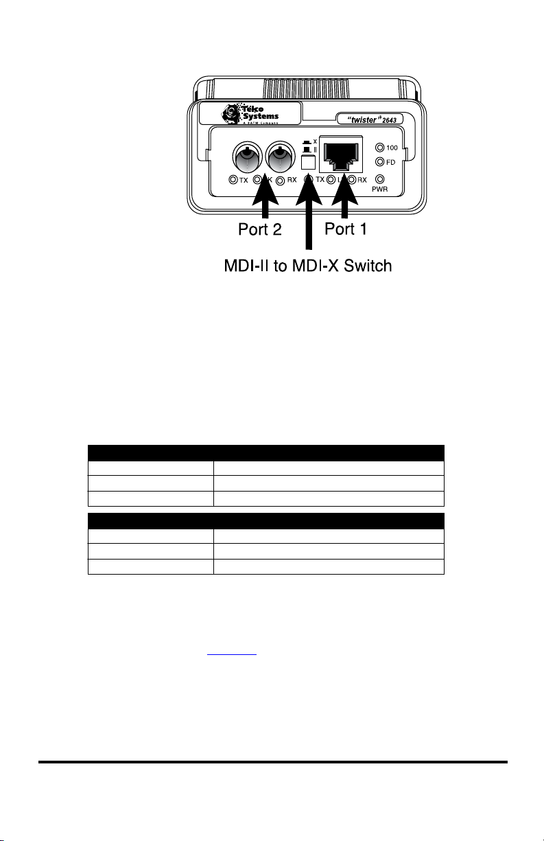
To eliminate the need for crossover cables, the 10/100 AutoTwister includes
an MDI-II to MDI-X switch for the twisted-pair port. This push-button
switch is located in the center of the front panel and allows setup in either
straight-through or crossover congurations. (See Figure 1.)
When setting the switch, observe the positioning of the following symbols:
Metrobility 10/100 AutoTwister 5
Page 6
A device that is wired straight through needs one crossover connection:
If the cable is…
straight through
crossover
… the MDI-II to MDI-X Switch Setting should be
X
II
A device that is wired crossover needs a parallel connection:
If the cable is…
straight through
crossover
… the MDI-II to MDI-X Switch Setting should be
II
X
Figure 1.
• The parallel symbol (II) indicates a straight through or parallel connec-
tion. Switch is out. (default)
• The cross symbol (X) indicates a crossover connection. Switch is in.
Use the tables below as a guide.
DIP Switches
The 10/100 AutoTwister includes a set of six DIP switches located on the
back of the unit. (See Figure 2.) These switches allow you to select the
operational mode best suited to your network’s conguration.
When setting DIP switches, the ON position is when the DIP switch is
6 Installation Guide
pushed up toward the top of the unit. The OFF position is when the DIP
switch is pushed down toward the bottom.
Page 7
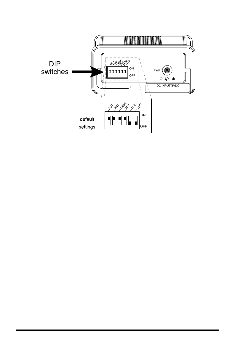
Figure 2.
Auto-Negotiation Switch (AN1)
*
Switch AN1 controls the use of auto-negotiation on the copper port. To
enable auto-negotiation, set the switch ON. To disable this function, set the
switch OFF. By default, auto-negotiation is enabled.
When the copper port has auto-negotiation enabled, it advertises 100Mbps
full duplex capabilities. When auto-negotiation is disabled, the port’s duplex
is determined by the FD1 switch, and its speed is set by the 100M1 switch.
10/100Mbps Switch (100M1)
*
Switch 100M1 controls the speed setting for the copper port. If auto-negotiation is disabled, the port speed will be the same as this switch setting,
where ON is 100Mbps and OFF is 10Mbps. The default speed setting is
100Mbps. When auto-negotiation is enabled, the 100M1 switch setting is
ignored.
Half/Full Duplex Switch (FD1, FD2)
Switch FD1 determines the duplex mode for the copper port if auto-negotiation is disabled. When auto-negotiation is enabled, the FD1 switch setting
is ignored. Switch FD2 determines the duplex mode on the ber optic port.
A port operates at full duplex when its FD switch is ON. It operates at half
duplex when its FD switch is OFF. The default is full duplex enabled.
*
*Changes to switches AN1, 100M1, FD1 and FD2 only come into effect after the power-cycle initialization.
Metrobility 10/100 AutoTwister 7
Page 8

Link Loss Return Switch (LLR2)
The 10/100 AutoTwister incorporates Link Loss Return (LLR) functional-
ity as an aid in troubleshooting remote connections on its ber optic port.
When LLR is enabled, the loss of the inbound link pulses on the port stops
the transmission of outbound link pulses on the same port. For example, if
LLR is enabled on port 2 and its receiver (RX) stops detecting link pulses,
then port 2’s transmitter (TX) will stop sending link pulses. LLR is not applicable to the copper port.
Link Loss Return is enabled on Port 2 when switch LLR2 is ON. The unit
is shipped with LLR disabled. Refer to Link Loss Return in the User Guide
section of this manual for more information.
Link Loss Carry Forward Switch (LLCF)
In addition to LLR, the AutoTwister supports Link Loss Carry Forward
functionality to help with troubleshooting remote connections.
Unlike LLR, which only applies to the ber port, LLCF affects both ports
on the AutoTwister. When LLCF is enabled, the loss of inbound link pulses
on a port stops the transmission of outbound link pulses on the opposite
port. For example, if LLCF is enabled, the loss of incoming link pulses at
Port 1 will stop the transmission of link pulses out of Port 2. Conversely, if
Port 2 stops receiving link pulses, Port 1 will not transmit link pulses.
Link Loss Carry Forward is enabled on both ports when switch LLCF is
ON. The unit is shipped with LLCF disabled. Refer to Link Loss Carry
Forward in the User Guide section of this manual for further details.
Use the following table to set the DIP switches to obtain specic modes of
operation. The conguration column lists the speed and duplex options for
Port 1 on the left and Port 2 on the right. “Auto” denotes that auto-negotiation is enabled.
8 Installation Guide
Page 9

noitarugifnoC
1troP2troP
1DF1NA1M0012DF
lluF001-otuAANNOANNO
flaH001-otuAANNOAN
flaH001-flaH01
lluF001-flaH01NO
flaH001-lluF01NO
lluF001-lluF01NONO
flaH001-flaH001NO
lluF001-flaH001NONO
flaH001-lluF001NONO
lluF001-lluF001NONONO
Connect to the Network
The Metrobility 10/100 AutoTwister offers the ease of plug-and-play
4
Fiber Optic Connections
installation.
• The 2643-13-01, 2643-15-01, 2643-1E-01, 2643-1G-01, and 2643-1K-01
provide one set of FX multimode SC/ST/MT-RJ/VF-45/LC connectors,
respectively, and support a maximum segment length of up to 2km for
remote links.
Set the switches ON
where indicated.
Set the switches
OFF for the blank
positions.
NA indicates the
switch setting is
not applicable and
can be either ON or
OFF.
• The 2643-14-01, 2643-16-01 and 2643-1M-01 provide one set of FX
singlemode SC/ST/LC connectors, respectively, and support a segment
length of up to 20km for remote links.
• The 2643-17-01 provides one set of FX singlemode SC connectors and
supports a maximum segment length of up to 40km for remote links.
• The 2643-1J-01 provides one set of FX singlemode SC connectors and
supports a maximum segment length of up to 100km for remote links.
Metrobility 10/100 AutoTwister 9
Page 10
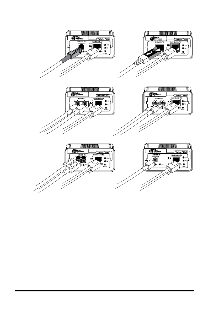
Figure 3.
BWDM Connection
The bidirectional wavelength division multiplexed (BWDM) port provides
one singlemode SC connector that supports a maximum segment length of
20km. BWDM line cards must always be used in complementary pairs. That
is, a -1X model must be connected to a -1Y. The -1X cards are designed to
transmit data at a wavelength of 1550nm and receive at 1310nm. Correspondingly, the -1Y cards transmit data at 1310nm and receive at 1550nm.
2643-1E
MT-RJ, RJ-45
2643-13, -14, -17, -1J
SC, RJ-45
2643-1K, -1M
LC, RJ-45
2643-1G
VF-45, RJ-45
2643-15, -16
ST, RJ-45
2643-1X, -1Y
BWDM SC, RJ-45
Twisted-Pair Connection
Each AutoTwister provides one shielded RJ-45 connector that supports
a maximum segment length of up to 100 meters. Use Category 3, 4 or 5
cables for 10Mbps segments; use only Category 5 or 5E cables for 100Mbps
segments.
10 Installation Guide
Page 11
NOTE: Be sure to properly set the MDI-II to MDI-X switch located between
PWR
DC INPUT/5VDC
OFF
ON
FD1
AN1
100M1
LLR2
FD2
LLCF
the two port connectors. Refer back to Step 3 if necessary.
Once power is applied to the unit, correct connectivity can be veried via
the link (LK) LEDs if a device is connected to the remote end of the cable.
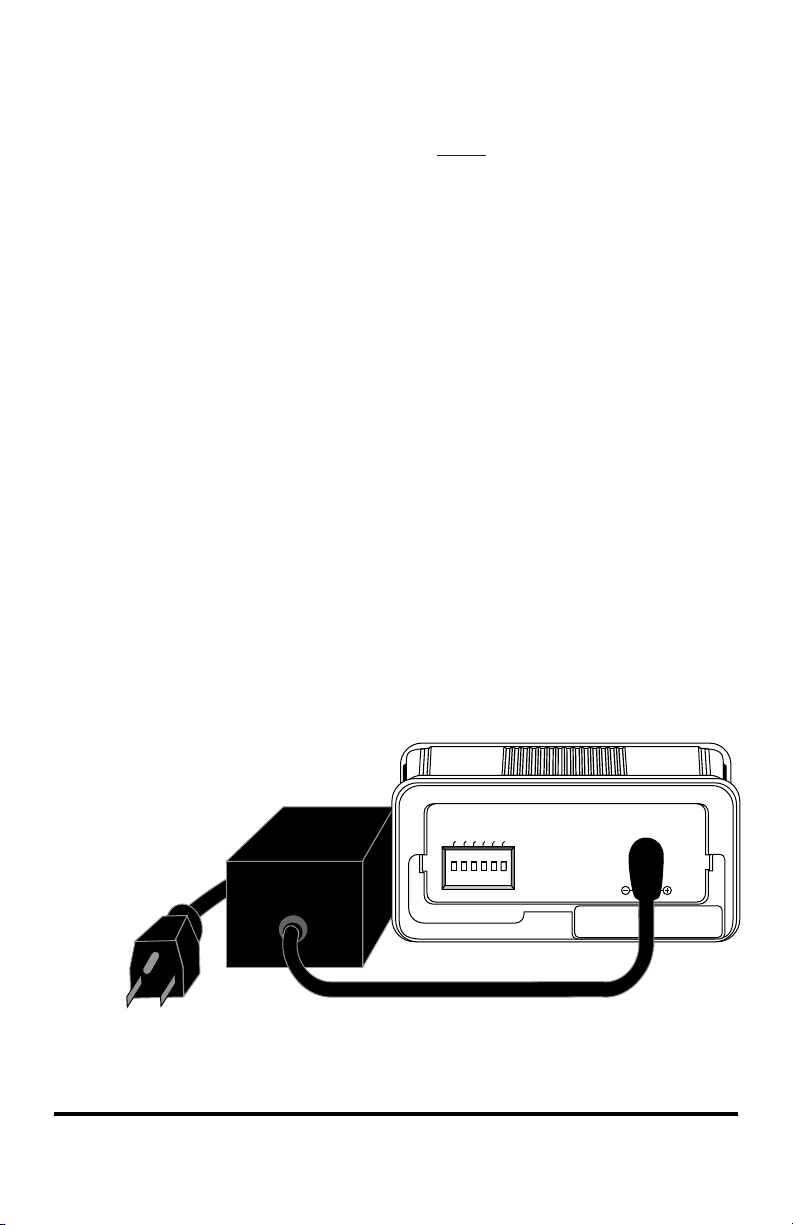
Apply Power
Power is applied to the AutoTwister from the desktop power supply. The
5
power supply is equipped with an S760 hollow-type plug for insertion into
the DC jack located on the back panel and the standard IEC 320-type AC
power receptacle. All standalone AutoTwister standalone units use a 90260V universal desktop power supply.
Connect the DC input jack located on the back of the AutoTwister before
connecting to the AC outlet.
Upon receiving power, the AutoTwister goes into normal operation mode
and automatically provides the appropriate signal translation between the
connected network segments.
Verify valid connections via the link (LK) LEDs on the AutoTwister’s front
panel.
Figure 4.
Metrobility 10/100 AutoTwister 11
Page 12

If an additional extension cord is used to connect the power supply to the
outlet, follow the guidelines below.
While one end of the AC power cord can be tted with a plug standard for
the country of operation, the end that connects to the AutoTwister’s power
supply must have a female plug that ts this type of AC receptacle.
• AC 115V (North American): Use a UL-listed and CSA-certied
cord set consisting of a minimum No. 18 AWG, type SVT or SJT
three-conductor cord (15 ft. maximum length) and a parallel blade,
grounding-type attachment plug rated 15A, 125V.
• AC 230V (USA): Use a UL-listed cord set consisting of a mini-
mum No. 18 AWG, type SVT three-conductor cord (15 ft. maximum length) and a Tandem blade grounding-type attachment plug
rated 15A, 250V.
• 240V (outside USA): Use a cord set consisting of a minimum No.
18 AWG cord and grounding-type attachment plug rated 15A,
250V. The cord set should have the appropriate safety approvals
for the country in which the AutoTwister is installed and marked
HAR.
12 Installation Guide
Page 13

User Guide
This section contains information regarding the operating features of the
Metrobility 10/100 AutoTwister.
LED Indicators
The Metrobility 10/100 AutoTwister provides several LEDs for the visible verication of unit status and proper functionality. The LEDs can assist in troubleshooting
and with overall network diagnosis and management. There are separate transmit,
receive and link indicators for each port. The twisted-pair port also has a speed LED
and a duplex LED.
After power is applied to the AutoTwister, verify correct connectivity via the link
LEDs.
LED
Label
PWR power green (steady) The unit is ON.
Copper Port LEDs
100 speed green (steady) The speed setting of the port is 100Mbps
FD duplex green (steady) The port is in full-duplex mode when lit.
RX receive green (blinking) The port is receiving data.
LK link green (steady) Veries that the port has a valid link.
TX transmit green (blinking) The port is sending data.
Fiber Port LEDs
RX* receive green (blinking) The port is receiving data, or the port is
LK* link green (steady) Veries that the port has a valid link.
TX transmit green (blinking) The port is sending data, or the port is
*RX and LK LEDs will blinking while Auto-Recovery (AR) is being attempted.
LED
Name
Color (Status) Function
when lit. It is 10Mbps when not lit.
It is in half-duplex when not lit.
attempting auto-recovery.
attempting auto-recovery.
Metrobility 10/100 AutoTwister 13
Page 14

Factory Settings
This section describes the preset features on the 10/100 AutoTwister. These settings
cannot be changed.
Full-Duplex Flow Control
The AutoTwister supports ow control on each port in full duplex only. Full-duplex
ow control is provided to avoid dropping packets during network congestion. If
there is no buffer space available for incoming packets, the AutoTwister will issue
a PAUSE frame. Full-duplex ow control is only applicable to ports operating in
full duplex with auto-negotiation enabled. Additionally, during auto-negotiation, the
port’s link partner must advertise that it supports PAUSE frames.
For ports operating at half duplex, the AutoTwister does not support any type of ow
control. If there are not enough buffers available, incoming packets will be dropped.
Auto-Recovery
The AutoTwister includes an auto-recovery circuit that allows you to transparently
connect a pair of AutoTwister units between two network devices. This enables you
to design a redundant path between 10Mbps and 100Mbps devices, allowing both
end devices to lose link if any part of the connection is broken.
To activate auto-recovery, all of the following conditions must be met:
• Auto-negotiation is disabled.
• LLR is enabled.
• LLCF is enabled.
When auto-recovery is enabled, the AutoTwister attempts to establish the ber link
between two back-to-back units. Because LLR is enabled on both AutoTwister stand-
alone units, auto-recovery is needed to prevent the two ber ports from ending up in
a deadlock situation with each ber port waiting for the other to transmit rst. Auto-
recovery allows the deadlock to be broken by periodically sending out pulses from
the ber port allowing the AutoTwister to reestablish its ber link if the line is intact.
14 User Guide
Page 15
Link Loss Return (LLR)
PC
Remote
Station
Switch/Hub
w/SNMP
Switch/Hub
w/SNMP
AutoTwisterAutoTwister
TP TPFiber
Cable
LED lit = established link LED unlit = no link
LLR is OFF
LLR is ON
PC
Remote
Station
Switch/Hub
w/SNMP
Switch/Hub
w/SNMP
AutoTwisterAutoTwister
Link Loss Returned
LED lit = established link LED unlit = no link
TP TPBroken
Fiber
Conductor
LLR is OFF LLR is ON
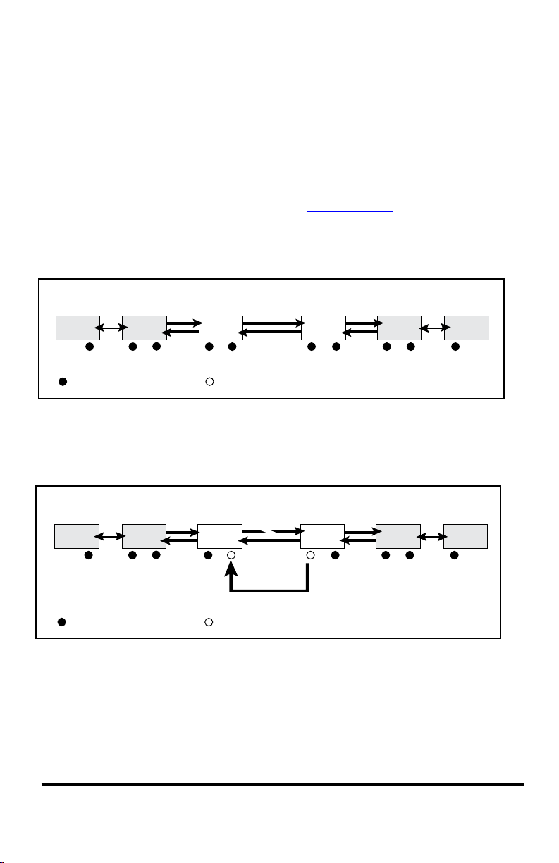
The ber optic ports of the Metrobility AutoTwister have been designed with LLR*
functionality for troubleshooting a remote connection.
When LLR is enabled, the ber port’s transmitter shuts down when its receiver fails
to detect a valid receive link. LLR is normally enabled on one end of the link and is
typically enabled on either the unmanaged or remote device. Setting LLR on both
ends of the link necessitates auto-recovery. See Auto-Recovery on page 17.
The diagram below shows a typical network conguration with good link status using AutoTwister standalone units for remote connectivity.
If one of the optical conductors is bad (as shown in the diagram box below), the
AutoTwister with LLR enabled will return a no-link condition to its link partner. This
aids the administrator in determining the source of the loss.
*Units are shipped with the LLR function disabled (OFF).
Metrobility 10/100 AutoTwister 15
Page 16
Link Loss Carry Forward (LLCF)
Management
Station
Management
Station
Switch/Hub
w/SNMP
Switch/Hub
w/SNMP
AutoTwisterAutoTwister
LED lit = established link LED unlit = no link
LLCF is ON LLCF is ON
Remote
Cable
Link Loss Carried Forward Link Loss Carried Forward
LED lit = established link LED unlit = no link
Management
Station
Management
Station
Switch/Hub
w/SNMP
Switch/Hub
w/SNMP
AutoTwisterAutoTwister
LLCF is ON LLCF is ON
Broken
Remote
Cable
Link Loss Carried Forward
LED lit = established link LED unlit = no link
Management
Station
Management
Station
Switch/Hub
w/SNMP
Switch/Hub
w/SNMP
AutoTwisterAutoTwister
LLCF is ON LLCF is ON
Broken
Cable
Remote
Cable
*
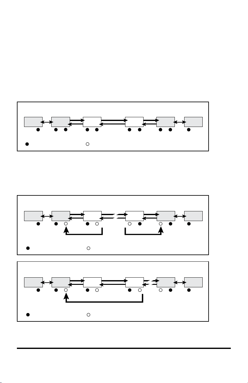
The AutoTwister incorporates LLCF for troubleshooting remote connections. When
LLCF is enabled, the ports do not transmit a link signal until they receive a link
signal from the opposite port.
The diagram below shows a typical network conguration with good link status
using Metrobility AutoTwister standalone units for remote connectivity. Note that
LLCF is enabled as indicated in the diagram below.
If a connection breaks, the AutoTwister standalone units carry that link loss forward
to the switch/hubs which generate a trap to the management stations. A network
administrator can then determine the source of the problem.
* Units are shipped with LLCF disabled (OFF).
16 User Guide
Page 17
Auto-Recovery
Switch/Hub
w/SNMP
Switch/Hub
w/SNMP
AutoTwisterAutoTwister
LED lit = established link LED unlit = no link
Fiber
Cable
Switch/Hub
w/SNMP
Switch/Hub
w/SNMP
AutoTwisterAutoTwister
LED lit = established link LED unlit = no link
Fiber
Cable
Link Loss
Carried Forward
Link Loss
Returned
Link Loss
Carried Forward
Switch/Hub
w/SNMP
Switch/Hub
w/SNMP
AutoTwisterAutoTwister
LED lit = established link LED unlit = no link
Fiber
Cable
Link Loss
Carried Forward
Link Loss
Returned
Link Loss
Carried Forward
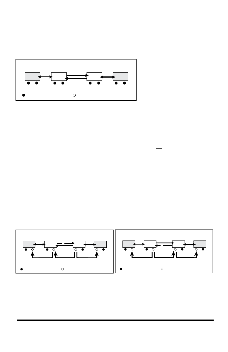
A typical application of the 10/100 AutoTwister is to use it in pairs to extend a network’s reach between two distant devices.
In this back-to-back setup, it may be desirable to see the entire link down if any of
the connecting segments fails. This means that both copper ports must relay a no link
condition to the switch/hub when any of the cables is broken.
For proper operation in this conguration, auto-recovery must be enabled. In the
standalone AutoTwister, auto-recovery is enabled only when all of the following
switches are set as indicated:
AN1 = disabled (OFF) LLR2 = enabled (ON) LLCF = enabled (ON)
Because LLR is enabled on both units, auto-recovery is required to prevent the two
ber ports from ending up in a deadlock situation, with each waiting for the other to
transmit rst. Auto-recovery allows the deadlock to be broken by periodically sending out pulses from the ber port forcing the AutoTwister to establish its ber link if
the line is intact.
The diagrams below show how the two switch/hubs are alerted to a broken ber
cable. Notice that both LLR and LLCF must be enabled under this condition.
Metrobility 10/100 AutoTwister 17
Page 18
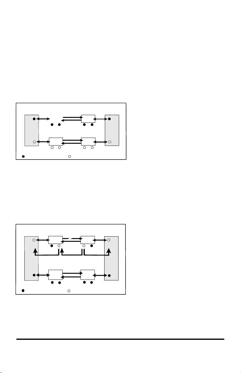
Auto-Recovery Application Example
100Mbps
Switch/Hub
10Mbps
Switch/Hub
AutoTwister A1 AutoTwister A2
Link Loss
Carried Forward
Link Loss
Returned
Link Loss
Carried Forward
AutoTwister B1
AutoTwister B2
Fiber
Cable
LED unlit = no linkLED lit = established link
100Mbps
Switch/Hub
10Mbps
Switch/Hub
AutoTwister A1 AutoTwister A2
LED lit = established link LED unlit = no link
Fiber
Cable
AutoTwister B1 AutoTwister B2
Fiber
Cable
A set of four AutoTwister standalone units can be used to provide the redundancy
necessary to ensure that data from a 100Mbps device reaches its destination in a
10Mbps device, as illustrated in the diagram below. In this example, the main link,
which includes the AutoTwister standalones A1 and A2, must be seen as a single
connection. If any of the cables in the main link fails, both switch/hubs must be noti-
ed of the failure so they can activate the backup link, which includes AutoTwister
units B1 and B2.
Since the entire main link must appear
down if any of its connecting segments fails, the copper ports of AutoTwister standalone A1 and A2 must
be able to indicate a no-link condition
to their corresponding switch/hubs.
To do this, auto-recovery must be
enabled on both AutoTwister units.
To enable auto-recovery on the
AutoTwister standalone units, make sure that on each unit AN1 is disabled, LLR2 is
enabled, and LLCF is enabled.
The diagram below illustrates how the two switch/hubs are alerted to a broken ber
cable in the main link, thus activating the backup link with AutoTwister standalones
B1 and B2.
Sequence of events:
• AutoTwister A1 stops transmitting
data to AutoTwister A2.
• AutoTwister A2 senses the loss
of link and stops transmitting link
pulses to AutoTwister A1 and the
10Mbps switch/hub.
• AutoTwister A1 receives the no
link condition and stops transmitting link pulses to the 100Mbps
switch.
• The 100Mbps and 10Mbps switch/hubs detect that the main link is down and
switch trafc to the backup link.
• Trafc resumes via the backup path with AutoTwister standalone units B1 and B2.
• Because auto-recovery is enabled, AutoTwister standalone units A1 and A2 try to
reestablish the ber link by periodically sending out pulses from their ber ports.
18 User Guide
Page 19
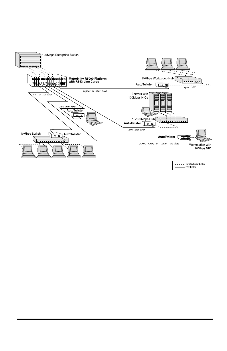
Topology Solutions
Metrobility 10/100 AutoTwister 19
Page 20

Technical Specications
Network Connections
Twisted-Pair Interface
Connector ______________________________________Shielded RJ-45, 8-pin jack
Impedance ____________________________________________100 Ohms nominal
Signal Level Output (peak differential) _________________.95 to 1.05V (100Mbps)
___________________2.2 to 2.8V (10Mbps)
Signal Level Input _____________________________ 200mV minimum (100Mbps)
_____________________________ 585mV minimum (10Mbps)
Supported Link Length ____________________________________________ 100m
Cable Type (10Mbps segments) ___________________ Category 3, 4 or 5 UTP/STP
(100Mbps segments) ___________________ Category 5 or 5E UTP/STP
Multimode Fiber Optic Interface
(2643-13-01, 2643-15-01, 2643-1E, 2643-1G-01, 2643-1K-01)
Connector _____________________________________ SC, ST, MT-RJ, VF-45, LC
Wavelength ___________________________________________________ 1310nm
RX Input Sensitivity ___________________________________ -31 dBm maximum
Output Power ___________________________ -23.5 dBm to -14 dBm (50/125 µm)
_________________________ -20 dBm to -14 dBm (62.5/125 µm)
Typical Link Budget ______________________________________________ 17 dB
Supported Link Length ________________________________up to 2km full duplex
Cable Type _____________________________________ 50/125, 62.5/125 µm F/O
Singlemode Fiber Optic Interface
(2643-14-01, 2643-16-01, 2643-1M-01)
Connector __________________________________________________ SC, ST, LC
Wavelength ___________________________________________________ 1310nm
RX Input Sensitivity ___________________________________ -31 dBm maximum
Output Power _______________________________-15 dBm to -8 dBm (9/125 µm)
Typical Link Budget ______________________________________________ 23 dB
Supported Link Length _______________________________up to 20km full duplex
Cable Type _______________________________________________9/125 µm F/O
Singlemode Fiber Optic Interface — long haul distance support
(2643-17-01)
Connector ________________________________________________________ SC
Wavelength ___________________________________________________ 1310nm
RX Input Sensitivity ___________________________________ -31 dBm maximum
Output Power ________________________________ -5 dBm to 0 dBm (9/125 µm)
Typical Link Budget ______________________________________________ 33 dB
Supported Link Length _______________________________up to 40km full duplex
Cable Type _______________________________________________9/125 µm F/O
20 User Guide
Page 21

Singlemode Fiber Optic Interface — extended long haul distance support
(2643-1J-01)
Connector ________________________________________________________ SC
Wavelength ___________________________________________________ 1550nm
RX Input Sensitivity ____________________________________-36 dBm minimum
Output Power _______________________________ -3 dBm to +2 dBm (9/125 µm)
Typical Link Budget ______________________________________________ 37 dB
Supported Link Length ______________________________up to 100km full duplex
Cable Type _______________________________________________9/125 µm F/O
Singlemode BWDM Fiber Optic Interface
Connector ________________________________________________________ SC
Supported Link Length _______________________________up to 20km full duplex
Cable Type _______________________________________________9/125 µm F/O
RX Input Sensitivity ____________________________________-32 dBm minimum
Output Power _______________________________-15 dBm to -8 dBm (9/125 µm)
Typical Link Budget ______________________________________________ 20 dB
(2643-1X-01)
TX Wavelength ____________________________________________ 1550nm
RX Wavelength ____________________________________________ 1310nm
(2643-1Y-01)
TX Wavelength ____________________________________________ 1310nm
RX Wavelength ____________________________________________ 1550nm
Data Rate
Data Rate _________________________________________ 10/100Mbps (Copper)
_____________________________________________ 100Mbps (Fiber)
Power
Input _____________________________________________ 90-260V AC 50/60 Hz
Output ______________________________________________ + 5V @ 1Amp, 5W
Environmental
Operating Temperature ________________________________________ 0° to 50° C
Storage Temperature ________________________________________ -25° to 70° C
Relative Humidity _______________________________ 5% to 95% non-condensing
Physical Case _____________________________ Fully enclosed metal construction
Dimensions ___________ 4.83" L x 3.26" W x 1.71" H (12.3 cm x 8.3 cm x 4.3 cm)
Weight (including power supply) ______________________________ 3 lbs, 1.36 kg
Metrobility 10/100 AutoTwister 21
Page 22

Product Safety, EMC and Compliance Statements
This equipment complies with the following requirements:
• UL • CSA
• CE • EN60950 (safety)
• FCC Part 15, Class B • EN55022 Class B (emissions)
• EN55024: 1998 (immunity) • ICES-003 Class B (emissions)
• IEC 825-1 Classication (eye safety) • Class 1 Laser Product (eye safety)
• CB
This product shall be handled, stored and disposed of in accordance with all governing and applicable safety and environmental regulatory agency requirements.
The following FCC and Industry Canada compliance information is applicable to
North American customers only.
USA FCC Radio Frequency Interference Statement
This equipment has been tested and found to comply with the limits for a Class B
digital device, pursuant to Part 15 of the FCC Rules. These limits are designed to
provide reasonable protection against harmful interference in a residential installation. This equipment generates, uses and can radiate radio frequency energy, and
if not installed and used in accordance with the instructions, may cause harmful
interference to radio communications. However, there is no guarantee that interference will not occur in a particular installation. If this equipment does cause harmful
interference to radio or television reception, which can be determined by turning the
equipment off and on, the user is encouraged to try to correct the interference by one
or more of the following measures:
—Reorient or relocate the receiving antenna.
—Increase the separation between the equipment and receiver.
—Connect the equipment into an outlet on a circuit different from that to which the
receiver is connected.
—Consult the dealer or an experienced radio/TV technician for help.
Caution: Changes or modications to this equipment not expressly approved by
the party responsible for compliance could void the user’s authority to operate the
equipment.
Canadian Radio Frequency Interference Statement
This Class B digital apparatus meets all requirements of the Canadian InterferenceCausing Equipment Regulations.
Cet appareil numérique de la classe B respecte toutes les exigences du Réglement sur
le matériel brouilleur du Canada.
22 User Guide
Page 23

Warranty and Servicing
Telco Systems’ Product Warranty
TELCO MAKES NO WARRANTIES EXCEPT AS HEREIN SET FORTH: Telco warrants that the equipment and accessories manufactured
by Telco, when used in the application and manner for which they are intended, will be free from defects caused by faulty material or poor
workmanship from the date of shipment. This warranty is subject to change at any time. The warranty that applies is that which is in effect at
the time the equipment ships. Warranty period is specic to particular product offerings. These periods are as follows:
Metrobility Products- 1 year
Telco’s liability under this warranty is limited to, the obligation, at Telco’s sole option, to repair or, to replace at Telco’s plant at Massachu-
setts, any part found to be defective under normal use and service within the warranty period specied herein, provided:
Though component parts of Telco-manufactured goods are covered by the above warranty, TELCO MAKES NO WARRANTY OF MER-
CHANTABILITY OR FITNESS FOR A PARTICULAR PURPOSE NOR ANY OTHER WARRANTY, EXPRESS OR IMPLIED, FOR ANY
EQUIPMENT OR MERCHANDISE NOT MANUFACTURED BY TELCO (FOR EXAMPLE BUT WITHOUT LIMITATION, ACCES-
SORIES AND AUXILIARY ITEMS).
However, Telco will cooperate reasonably with Purchaser in attempting to secure, where possible, the benet of any warranties which the
manufacturer of such non-Telco items may provide. All ordered replacement parts or parts replaced during the warranty period assume the
unexpired portion of the original parts warranty or ninety (90) days from date of shipment, whichever is longer.
Replacement, Repair or Refund Procedure for Hardware: Telco’s sole obligation under this express warranty shall be, at Telco’s option
and expense, to repair the defective product or part or deliver to Customer an equivalent product or part to replace the defective item. All
products that are replaced will become the property of Telco Systems. Replacement products or parts may be new or reconditioned. Telco
warrants any replaced or repaired product or part for ninety (90) days from shipment, or the remainder of the initial warranty period, whichever is longer. Telco reserves the right to refund the purchase price paid for the defective product as its exclusive warranty remedy.
To Receive a Return Materials Authorization (RMA) Number: Please contact the party from whom you purchased the product. If you
purchased the product directly from Telco Systems, contact the Telco Systems Customer Care Group.
Software: Telco warrants to Customer that each software program licensed from it will, if operated as directed in the user documentation,
substantially achieve the functionality described in the user documentation for a period of ninety (90) days from the date of purchase from
Telco or its authorized reseller. No updates or upgrades are provided under this warranty. Telco’s sole obligation under this express warranty
shall be, at Telco’s option and expense, to refund the purchase price for the software product or replace the software product with software
which meets the requirements of this warranty as described above. Customer assumes responsibility for the selection of the appropriate
programs and associated reference materials. Telco expressly disclaims any warranty or representation that its software products will meet
Customer’s requirements or work in combination with any hardware or software products provided by third parties, that the operation of the
software products will be uninterrupted or error free, or that all defects in the software products will be corrected.
The foregoing warranties are in lieu of any and all other warranties, expressed or implied, including, but not limited to, warranties of
merchantability, tness for a particular purpose or against infringement of any rights of third parties. Telco’s liability on any claim for money
damages (including, without limitation negligence for any loss or damage arising out of, connected with, or resulting from the sale of products
hereunder, or from the performance or breach thereof, or from the design, manufacture, sale, delivery, resale, installation, inspection, repair,
operation or use of any merchandise manufactured by Telco) shall in no case exceed the price allocable to the merchandise or part thereof
which gave rise to the claim. Purchaser will hold Telco harmless with respect to any claims or actions by third parties. In particular, Telco
expressly disclaims and shall in no event be liable for any indirect, special, incidental or consequential damages.
IP and EdgeGate Products – 1 year
a) Telco is promptly notied in writing upon discovery of such defects;
b) The defective parts are returned to Telco, transportation charges prepaid in accordance with Telco’s instructions;
c) Telco’s examination shall disclose to its satisfaction that such defects have not been caused by misuse, abuse, neglect,
accident, or adjustments other than those specied in the Telco Operating and Maintenance Manual. Telco shall have no responsibility under this warranty for defects, which have been caused by misuse, abuse, improper application, repair, alteration,
accident or negligence in use, storage, transportation or handling. Further, the original identication markings must not have
been removed, defaced or altered.
d) Equipment has been installed and operated, and maintained, in complete accordance with the Telco Operating and Maintenance Manual, and good engineering practice.
Metrobility 10/100 AutoTwister 23
Page 24

US Headquarters
15 Berkshire Road
Manseld MA USA 02048
tel: 1.781.551.0300 • fax: 1.781.255.2344
www.telco.com
5660-264313 N
12/10
 Loading...