

PA 15 - USER MANUAL
Photoelectric Amplifier
1-channel manual photoelectric amplifier
Website: www.telcosensors.com
tel
EN
Product Data
Electrical Data
Supply voltage 15-30 V dc / 24V ac
Power consumption Max. 2,5 W
Output: relay 250 VAC / 3 A, 120 VAC /5 A
Output: transistor PNP/NPN 30 V dc/ 60 mA
Alarm output PNP: 12 V dc / 10 mA NPN: 12-30 V dc / 10 mA
Environmental Data
Temperature, operation -10 to +50 °C
Sealing class IP 40
Approvals
Applicable Remote Sensors & Sensing Ranges
Series LT/LR Sensing Range
100 18 m
110 40 m
120 70 m
Comments:
The range is reduced to 30 % in short range mode.
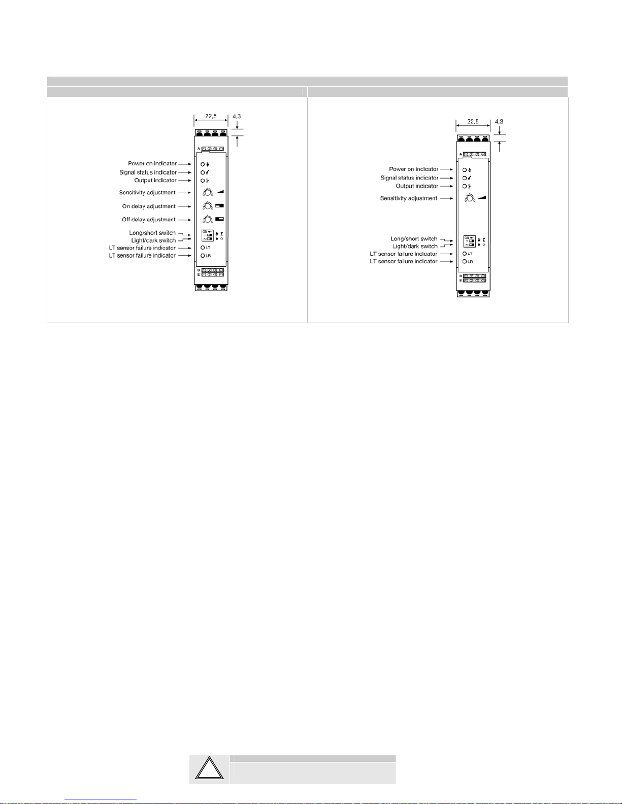
Illustration
Please, refer to figure nº 1.
Indicators
Power On Green light when power is on
Signal OK Green light when signal level is sufficient and light beam is unbroken
Output Yellow light when output is activated
LT error Red light flashes for light transmitter error (disconnection or shorted)
LR error Red light flashes for light receiver error (disconnection or shorted)
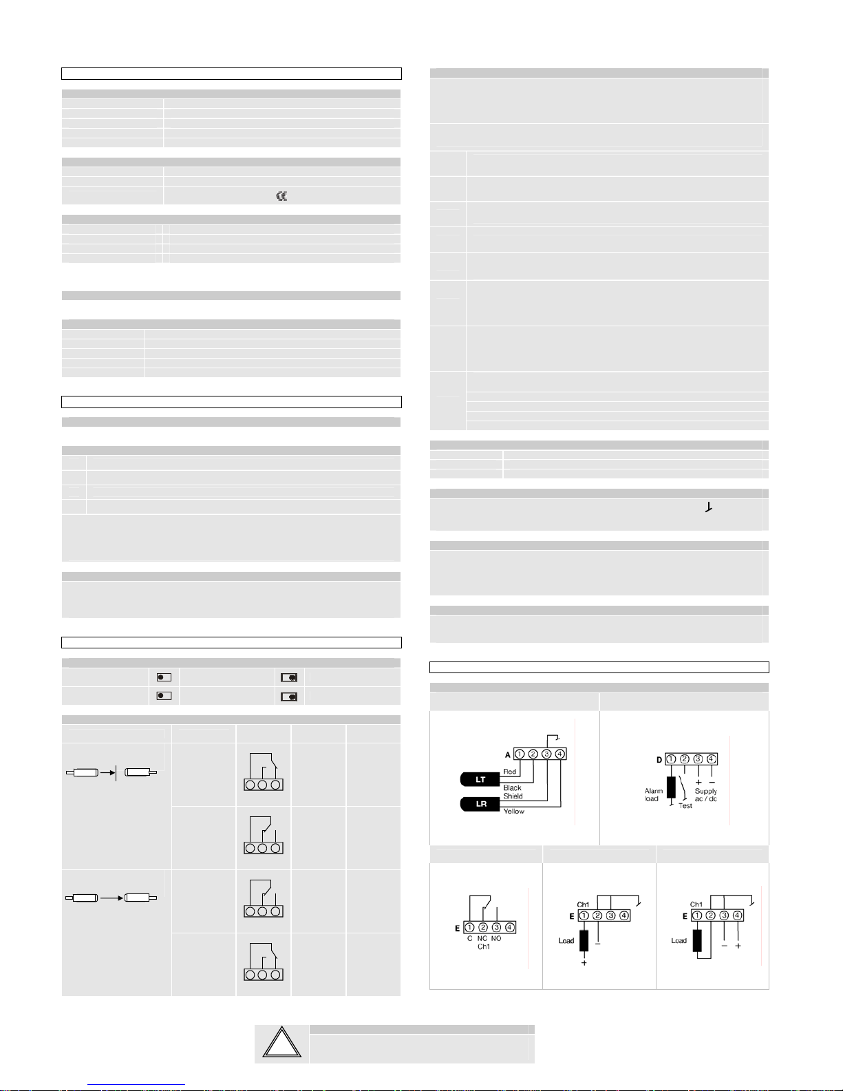
Connection
Wiring Diagrams
Please, refer to figure nº 2.
Connection Steps
1 Check the power supply complies with electrical data.
2 Make sure power is off. Mount the amplifiers in the DIN rail.
3 Connect all wires to the terminals according to wiring diagrams.
4 Switch power on.
Notes:
- The PNP output can optionally be supplied connecting + to terminal E4 and connecting – to
the terminals E3.
- The NPN output can optionally be supplied connecting + to the load and– to terminal E2 or
E3.
Bus Connection
Up to 10 amplifiers can be supplied by one PPB power supply. Connect the amplifiers and the
PPB power supply on the DIN rail using the special bus connectors.
Do not connect wires for power supply to the amplifiers only to the PPB. The PPB will supply
the amplifier through the bus.
Adjustments
Selectors
Long/short range
Long range
Short range
Light/dark operated
Dark operated (NC)
Light operated (NO)
Output Logic
Detection (thru beam) Output mode
Relay
Output
Transistor
output
Output
indicator
Dark operated
CNCNO
Closed On
Object present
Light operated
CNCNO
Open Off
Dark operated
CNCNO
Open Off
object absent
Light operated
CNCNO
Closed On
Sensitivity Adjustment
Sensitivity can be adjusted in two large steps with long/ short range selector or continuously
with the potentiometer. Maximum sensitivity and long range can be used for most applications
and is advised for applications with contaminated environments e.g. dirt, water and dust.
Choose long range and increase the sensitivity to maximum by turning the potentiometer to full
clockwise position.
More accurate sensitivity adjustment may be required in applications where objects to be
detected are small or translucent. Proceed with the following steps:
1
Make sure there is no object present between remote transmitter and receiver
sensors.
2 Select long or short range according to application.
3
Increase sensitivity slowly from minimum (full anti clockwise) until the yellow output
indicator changes. Increase a little further until the green Signal OK indicator is on.
4 Select target object with smallest dimensions and most translucent surface.
5
Place target object between remote transmitter and receiver sensors. If the output
changes, the sensitivity is adjusted correct. If the output do not change proceed to
step 6.
6
Remove the object and decrease the sensitivity by turning the potentiometer
counter clockwise until the green Signal OK indicator is off and the LT/LR error
indicator are constantly on.
7
Place target object between remote transmitter and receiver sensors. If the output
changes the sensitivity is adjusted to suit the target but the adjustment is very
delicate and not advisable, please contact your vendor for further information.
If the signal level is insufficient, the LT/LR error indicator will switch on with red and
yellow light. Check the following:
Check alignment of sensors
Check transmitter and receiver sensors are within sensing range
Check sensitivity adjustment
Check sensor heads are not excessively contaminated
Potentiometers
Sensitivity Range adjustment
On delay Delay on activation of output can be adjusted between 0 s and 10 s
Off delay Delay on de-activation of output can be adjusted between 0 s and 10 s
Test Input
The transmitter is disabled if the test input is connected to the internal ground . Make sure
no object is present in the detection area, between remote transmitter and receiver sensor,
when test is activated. When the transmitter is disabled, a change in output will occur.
Alarm output
The alarm output of D1 is ON (high for PNP and relay output types and low for NPN output
type) if the amplifier does not indicate errors and OFF if it indicates an error.
The indicated errors are:
- LT/LR error, the alarm output is flashing ON/OFF
- Insufficient signal level, the alarm output is OFF.
Time Delay Adjustment
The on delay enables output signal to only activate if an object in the detection area is present
for the adjusted time period. The off delay enables output signal to remain activated for the
adjusted time period. The time delay is adjustable between 0-10 s.
Connection
Connections
Sensors Connections Power supply, Alarm output and Test input
Relay output NPN output PNP output
LT
LR
LT LR
Notice that the terminals can be pulled out as plugs.
Warning
V 1.0 Part Number: 0666220670
E-Mail: info@telcosensors.com
June 2008 edition
Made in Denmark
This product is not a safety system and must not be used as such.
It is not designed for personnel safety app lications, and must not be used
as a stand alone personnel safety system.
Telco A/S reserves the right to make changes without prior notice
!
PA 15 - USER MANUAL
Photoelectric Amplifier
1-channel manual photoelectric amplifier
Website: www.telcosensors.com
tel
EN
Ilustration Fig. 1
PA 15 A PA 15 B
Warning
V 1.0 Part Number: 0666220670
E-Mail: info@telcosensors.com
June 2008 edition
Made in Denmark
This product is not a safety system and must not be used as such.
It is not designed for personnel safety app lications, and must not be used
as a stand alone personnel safety system.
Telco A/S reserves the right to make changes without prior notice
!
 Loading...