

TelCom Semiconductor Inc TC71EPA, TC71EOA, TC71CPA, TC71COA, TC70COA Datasheet
...
TC70/71
MICROMASTER™ – SYSTEM SUPERVISOR WITH POWER SUPPLY
MONITOR, W A TCHDOG AND BA TTER Y BACKUP
1
2
FEATURES
■ Maximum Functional Integration: Precision Power
Supply Monitor, Watchdog Timer, External RESET
Override, Threshold Detector and Battery Backup
Controller in an 8-Pin Package
■ Generates Power-on RESET and Guards Against
Unstable Processor Operation Resulting from
Power "Brown-out"
■ Automatically Halts and Restarts an Out-of-
Control Microprocessor
■ Output Can be Wire-ORed, or Hooked to Manual
RESET Pushbutton Switch
■ Watchdog Disable Pin for Easier Prototyping
(TC70)
■ Voltage Monitor for Power Fail or Low Battery
Warning (TC71)
■ Available in 8-Pin Plastic DIP or 8-Pin SOIC
Packages
■ Cost Effective
TYPICAL APPLICATIONS
■ All Microprocessor-based Systems
■ Test Equipment
■ Instrumentation
■ Set-Top Boxes
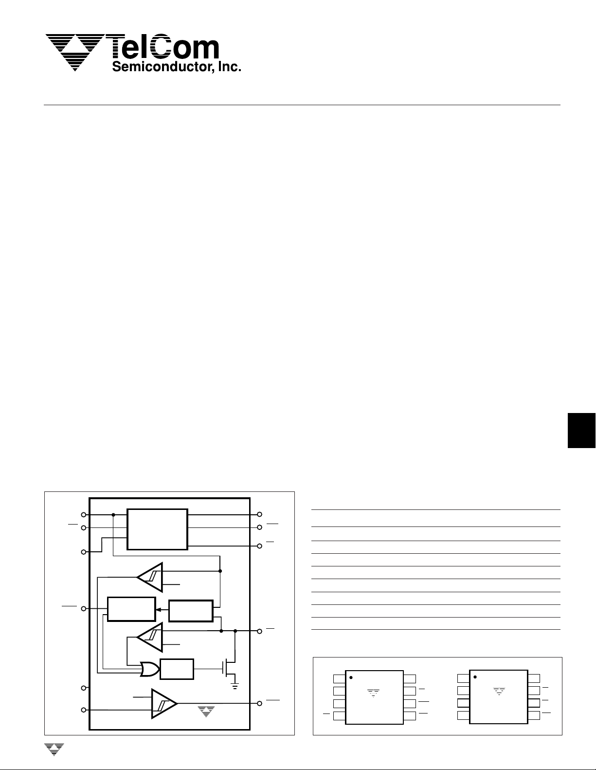
FUNCTIONAL BLOCK DIAGRAM
V
CC V
CEI
(TC70)
V
BATT
WDD
(TC70)
GND
TDI
(TC71)
WATCHDOG
V
REF3
TIMER
BATTERY
BACK-UP
CONTROL
DELAY
TIMER
V
REF1
∆V
DETECTOR
V
REF2
TC70/71
TELCOM SEMICONDUCTOR, INC.
CCO
CEO
(TC70)
PF
(TC71)
RS
TDO
(TC71)
GENERAL DESCRIPTION
The TC70/71 is a fully-integrated power supply monitor,
watchdog and battery backup circuit in a space-saving
8-pin package.
When power is initially applied, the TC70/71 holds the
processor in its reset state for a minimum of 500msec after
VCC is in tolerance to ensure stable system start-up. After
start-up, processor sanity is monitored by the on-board
watchdog circuit. The processor must provide periodic highto-low level transitions to the TC70/71 to verify proper
execution. Should the processor fail to supply this signal
within the specified timeout period, an out-of-control processor is indicated and the TC70/71 issues a momentary
processor reset as a result. The TC70 also features a
watchdog disable pin to facilitate system test and debug.
The output of the TC70/71 can be wire-ORed to a pushbutton switch (or electronic signal) to reset the processor.
When connected to a push-button switch, the TC70/71
provides contact debounce.
The integrated battery backup circuit on-board the TC70/
71 converts CMOS RAM into nonvolatile memory by first
write-protecting, then switching the VCC line of the RAM over
to an external battery.
The TC71 incorporates an additional 1.3V threshold
detector for power fail warning, low battery detection or to
monitor power supply voltages other than +5V.
ORDERING INFORMATION
Part No. Package Temp. Range
T
C70COA 8-Pin SOIC 0°C to +70°C
TC70CPA 8-Pin Plastic DIP 0°C to +70°C
TC70EOA 8-Pin SOIC – 40°C to +85°C
TC70EPA 8-Pin Plastic DIP – 40°C to +85°C
T
C71COA 8-Pin SOIC 0°C to +70°C
TC71CPA 8-Pin Plastic DIP 0°C to +70°C
TC71EOA 8-Pin SOIC – 40°C to +85°C
TC71EPA 8-Pin Plastic DIP – 40°C to +85°C
PIN CONFIGURATIONS (DIP and SOIC)
V
1
CCO
V
27
CC
GND
CEI
TC70
3
4
V
8
BATT
RS
6
WDD
5
CEO
V
1
CCO
V
27
CC
3
GND
4
TDI
TC71
TC70/71-1 11/18/96
V
8
BATT
RS
PF
6
5
TDO
5-7
3
4
5
6
7
8
TC70/71
MICROMASTER™ – SYSTEM SUPERVISOR
WITH POWER SUPPL Y MONITOR, W A TCHDOG
AND BA TTER Y BACKUP
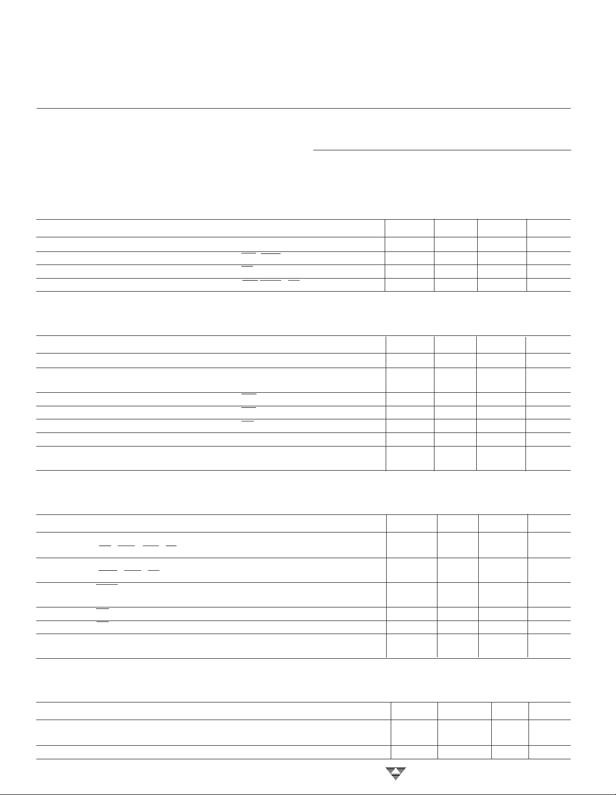
ABSOLUTE MAXIMUM RATINGS*
Voltage (Any Pin) with Respect to
Ground................................ GND – 0.3 to VCC + 0.3V
Operating Temperature Range ...............– 40°C to +85°C
ELECTRICAL CHARACTERISTICS: Recommended DC Operations: T
A
= T
MIN
to T
MAX,
Storage Temperature Range ................– 65°C to +150°C
Lead Temperature (Soldering, 10 sec) .................+300°C
*This is a stress rating only and functional operation of the device at these
or any other conditions above those indicated in the operational sections of
the specifications is not implied. Exposure to Absolute Maximum Rating
Conditions for extended periods may affect device reliability.
unless otherwise specified.
Symbol Parameter Test Conditions Min Typ Max Unit
V
CC
V
IH
V
IH
V
IL
Supply Voltage Note 1 4.5 5.0 5.5 V
Input HIGH Level CEI, WDD (Note 1) 2.5 — — V
Input HIGH Level RS (Note 1) 2.2 — — V
Input LOW Level CEI, WDD, RS (Note 1) — — 0.8 V
ELECTRICAL CHARACTERISTICS: DC: T
Symbol Parameter Test Conditions Min Typ Max Unit
I
CC1
I
CC2
I
IH
I
IL
I
IH
I
STBY
I
STBY
A
= T
MIN
to T
, VCC = 4.5V to 5.5V, unless otherwise specified.
MAX
Operating Current Notes 2, 3 — 5 6.5 mA
Operating Current in VCC = 0; V
= 2.8V; (Note 3) — 0.01 0.20 µA
BATT
Battery Backup Mode
Input Leakage CEI — 4 7 µA
Input Leakage CEI — 1 — µA
Input Leakage RS — 1 — µA
Battery Standby Current 5.5V > VCC > V
Battery Standby Current 5.5V > VCC > V
+ 0.2V – 1.0 — 0.02 µA
BATT
+ 0.2V – 0.1 — 0.02 µA
BATT
TA = 25°C
ELECTRICAL CHARACTERISTICS:
DC: Power Supply Monitor, EXT. RESET and Watchdog:
Symbol Parameter Test Conditions Min Typ Max Unit
I
OL
I
OH
WDD
I
V
STH
V
STL
V
CCTRIP
Output Current 0.4V VOL = 0.4V 2 5 — mA
(RS, TDO, CEO, PF Pins)
Output Current 2.4V VOH = 2.4V 2 3 — mA
(TDO, CEO, PF Pins)
WDD Input Current WDD = GND – 120 — — µA
WDD = V
RS Strobe (HIGH) Level Figure 3 (Note 1) VDD – 0.5 — — V
RS Strobe (LOW) Level Figure 3 (Note 1) 2.2 — VDD – 1.8 V
VCC Trip Point (Note 1) 0°C ≤ TA ≤ 70°C 4.25 — 4.49
– 40°C ≤ TA ≤ 85°C 4.20 4.49
CC
TA = T
MIN
to T
, VCC = 4.5V to 5.5V,
MAX
——25
unless otherwise specified.
ELECTRICAL CHARACTERISTICS:
DC: Battery Backup and Threshold Detector:
Symbol Parameter Test Conditions Min Typ Max Unit
V
V
5-8
OUT1
OUT2
V
Output Voltage I
CCO
V
in Battery Backup Mode
OUT
TA = T
= 1mA VCC – 0.3 VCC – 0.1 — V
OUT
I
= 50mA VCC – 0.5 VCC – 0.20 —
OUT
I
= 250µA, VCC < V
OUT
MIN
to T
, VCC = 4.5V to 5.5V, unless otherwise specified.
MAX
BATT
– 0.2, V
BATT
= 2.8V
V
BATT
– 0.1 V
BATT
– 0.02
— V
TELCOM SEMICONDUCTOR, INC.
MICROMASTER™ – SYSTEM SUPERVISOR
WITH POWER SUPPL Y MONITOR, W A TCHDOG
AND BA TTER Y BACKUP
TC70/71
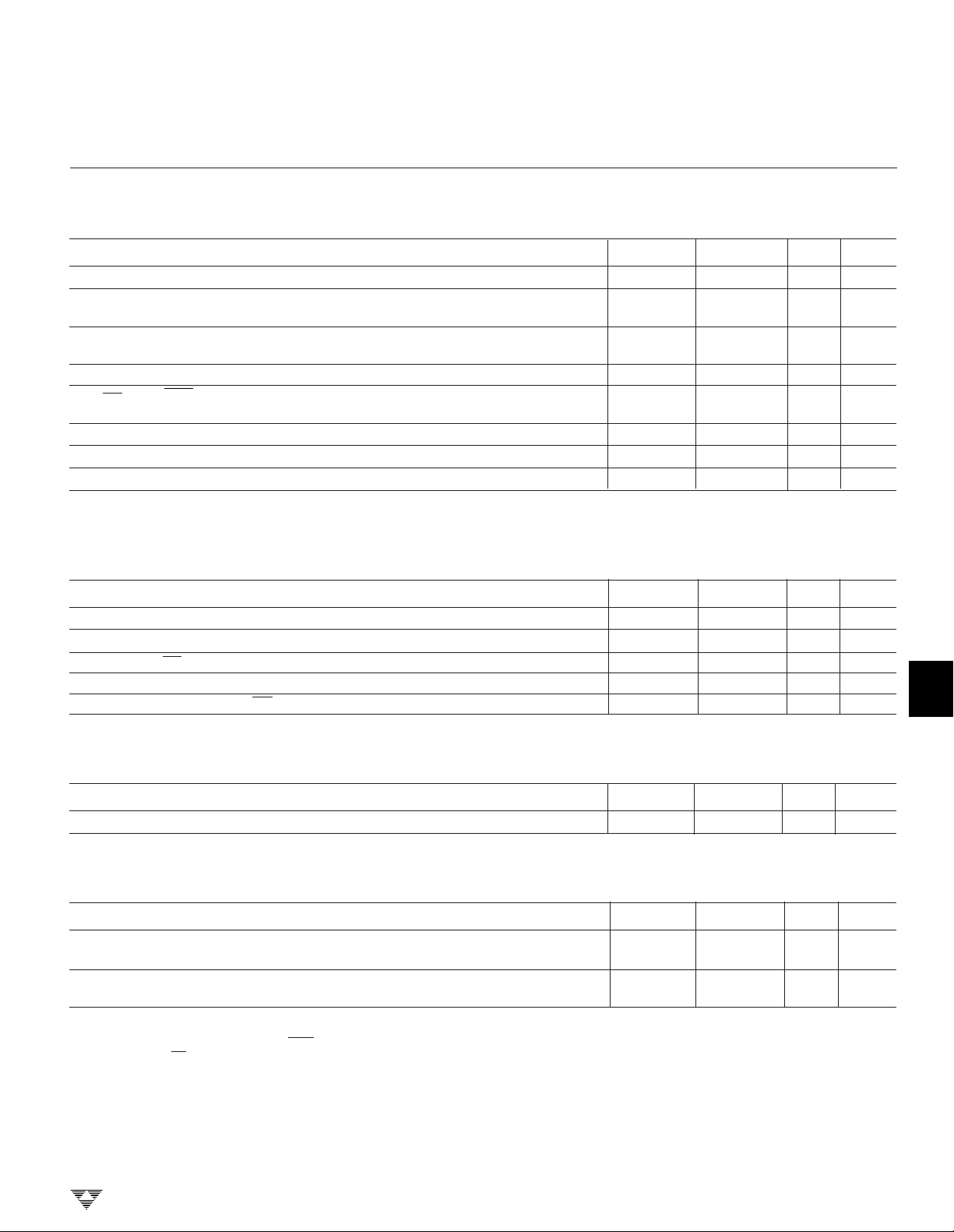
ELECTRICAL CHARACTERISTICS: (Cont.)
DC: Battery Backup and Threshold Detector:
Symbol Parameter Test Conditions Min Typ Max Unit
I
OUT1
I
OUT2
V
SW
V
HYST
VOH
CEO
V
TDI
I
TDI
V
TDI (HYST)
V
Output Current VCC = 4.5V, V
CCO
V
Output Current in V
CCO
Battery Backup Mode V
Battery Switchover Threshold —
(VCC Falling)
Battery Switchover Hysteresis — 20 — mV
CEO Output Voltage in VCC < V
Battery Backup Mode IOH = 10µA
Threshold Detector Trip Voltage 1.2 — 1.4 V
Threshold Detector Input Current TA = 25°C –25 — +25 nA
Threshold Detector Hysteresis — 10 — mV
CCO
BATT
TA = T
= V
= 2.8V
BATT
to T
MIN
CCO
– 0.3V 500 — — µA
BATT
– 0.2, V
, VCC = 4.5V to 5.5V, unless otherwise specified.
MAX
= 3.5V 50 100 — mA
V
= 2.8V V
BATT
– 0.01
BATT
– 0.2 — — V
BATT
—V
1
2
3
ELECTRICAL CHARACTERISTICS: AC: Power Supply Monitor, EXT. RESET and Watchdog:
Symbol Parameter Test Conditions Min Typ Max Unit
t
PBH
t
RST
t
ST
t
TD
t
RPD
PB Hold Time Figure 4 (Note 4) 20 — — msec
Reset Active Time Figure 6 500 — 900 msec
RS STROBE Pulsewidth Figure 3 500 — — nsec
Watchdog Timeout Period Figure 3 500 700 900 msec
VCC Detect to RS LOW Figure 6 — — 100 nsec
TA = T
MIN
specified.
to T
, VCC = 4.5V to 5.5V, unless otherwise
MAX
ELECTRICAL CHARACTERISTICS:
AC: Battery Backup and Threshold Detector:
Symbol Parameter Test Conditions Min Typ Max Unit
t
PD
CE Propagational Delay Figure 7 — — 50 nsec
TA = T
MIN
to T
, VCC = 4.5V to 5.5V, unless otherwise specified.
MAX
ELECTRICAL CHARACTERISTICS:
AC:
TA = T
Symbol Parameter Test Conditions Min Typ Max Unit
t
F
t
R
NOTES: 1. All voltages referenced to ground.
to T
MIN
VCC Fall Time From Figure 5 (Note 1) 10 — — µsec
4.25V to 3.0V
VCC Rise Time From Figure 5 (Note 1) 0 — — µsec
3.0V to 4.25V
2. No output load.
3 Measured with V
4. The RS output must be held low for a minimum of 20msec to guarantee a reset.
MAX
.
CCO
and CEO open.
4
5
6
7
TELCOM SEMICONDUCTOR, INC.
8
5-9
 Loading...