

TelCom Semiconductor Inc TC623HVOA, TC623HEPA, TC623HCPA, TC623HEOA, TC623HCOA Datasheet
...
2-25
TELCOM SEMICONDUCTOR, INC.
7
6
5
4
3
1
2
8
3V , DUAL TRIP POINT TEMPERA TURE SENSOR
TC623
FEATURES
■ Integrated Temp Sensor and Detector Operate
from a Supply Voltage as Low as 2.7V
■ Replaces Mechanical Thermostats and Switches
■ On-Chip Temperature Sense
■ 8-Pin DIP or SOIC for Direct PCB Mounting
■ 2 User-Programmable Temperature Set Points
■ 2 Independent Temperature Limit Outputs
■ Heat/Cool Regulate Output
APPLICATIONS
■ CPU Thermal Management
■ System Over-or Under-Temperature Shutdown
■ Advanced Thermal Warning
■ Fan Speed Control Circuits
■ Accurate Appliance Temperature Sensing
■ Environmental Control
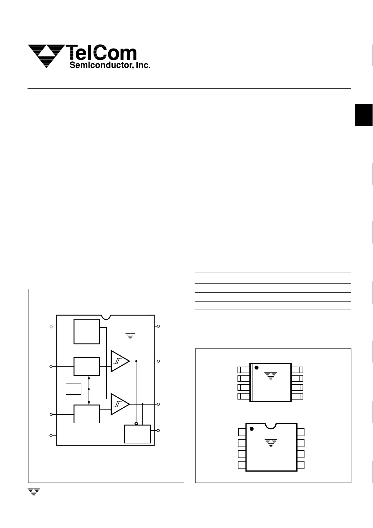
GENERAL DESCRIPTION
The TC623 is a 3V solid-state, programmable temperature sensor designed for use in thermal management applications. It features dual thermal interrupt outputs (LOW
LIMIT and HIGH LIMIT) each of which program with a single
external resistor. The HIGH LIMIT and LOW LIMIT outputs
are driven active (high) when measured temperature equals
the user-programmed limits. The CONTROL output is driven
active (high) when temperature equals the HIGH LIMIT
setpoint, and turned off when temperature falls below the
LOW LIMIT setpoint. The CONTROL output can be used to
provide simple ON/OFF control to a cooling fan if so desired.
Low voltage operation, easy setpoint programming,
small size and low cost make the TC623 an ideal choice for
many thermal management applications.
ORDERING INFORMATION
Temperature
Part No. Package Range
TC623CCOA 8-Pin SOIC 0°C to +70°C
TC623CCPA 8-Pin Plastic DIP 0°C to +70°C
TC623CEOA 8-Pin SOIC – 40°C to +85°C
TC623CEPA 8-Pin Plastic DIP – 40°C to +85°C
TC623CVOA 8-Pin SOIC – 40°C to +125°C
FUNCTIONAL BLOCK DIAGRAM
3
HIGH SET
2
LOW SET
1
NC
4
GND
5
CONTROL
6
HIGH LIMIT
V
CC
7
LOW LIMIT
8
LATCH
Q
SR
+
+
–
–
TC623
R < R
LOW HIGH
VREF
GEN.
VREF
GEN.
VREF
TEMP
TO
VOLTAGE
CONVERTER
GND
HIGH SET
LOW SET
NC
GND
HIGH SET
LOW SET
NC
V
CC
HIGH LIMIT
CONTROL
LOW LIMIT
V
CC
HIGH LIMIT
CONTROL
LOW LIMIT
8
7
6
5
1
2
3
4
1
8
2
7
3
6
4
5
TC623CCOA
TC623CEOA
TC623CVOA
TC623CCPA
TC623CEPA
PIN CONFIGURATION (DIP and SOIC)
NOTE: Latch Q Output, ("C" Option), is a Standard Device. Contact
Factory for Latch Q Output, ("H" Option).
TC623-5 9/18/96

2-26
TELCOM SEMICONDUCTOR, INC.
Maximum Chip Temperature.................................+150°C
Storage Temperature ............................– 65°C to +150°C
Lead Temperature (Soldering, 10 sec) .................+300°C
*Static-sensitive device. Unused devices must be stored in conductive
material. Protect devices from static discharge and static fields. Stresses
above those listed under "Absolute Maximum Ratings" may cause permanent damage to the device. These are stress ratings only and functional
operation of the device at these or any other conditions above those
indicated in the operation sections of the specifications is not implied.
Exposure to absolute maximum rating conditions for extended periods may
affect device reliability.
ABSOLUTE MAXIMUM RATINGS*
Package Power Dissipation (TA ≤ 70°C)
Plastic DIP ......................................................730mW
SOIC...............................................................470mW
Derating Factors
Plastic DIP .................................................... 8mW/°C
SOIC............................................................. 6mW/°C
Supply Voltage ...........................................................5.5V
Input Voltage Any Input....... (GND – 0.3V) to (VDD +0.3V)
Operating Temperature
V Version ........................................– 40°C to +125°C
E Version ..........................................– 40°C to +85°C
C Version...............................................0°C to +70°C
Figure 1. TC623 Sense Resistors vs. Trip Temperature
DETAILED DESCRIPTION
TC623 Operation
The TC623 consists of a positive temperature coefficient (PTC) temperature sensor and dual threshold detector. Temperature set point programming is easily accomplished with external programming resistors from the HIGH
SET and LOW SET inputs to VCC. The HIGH LIMIT and LOW
LIMIT outputs remain inactive (low) as long as the measured
temperature is below setpoint values. As temperature in-
creases, the LOW LIMIT is driven high when temperature
equals the LOW LIMIT setpoint (±3°C). If temperature
continues to climb, the HIGH LIMIT output is driven high
when temperature equals the HIGH LIMIT setpoint (±3°C).
Figure 1 shows the relationship between the sense resistance values and trip point temperature.
The CONTROL output is driven high when the HIGH
LIMIT output goes high, and is reset low when the LOW
LIMIT output goes low. This output provides the logic for
simple ON/OFF fan control. Figure 2 shows overall TC623
operation.
Figure 2. TC623 Temperature vs. Output
ELECTRICAL CHARACTERISTICS
Over Operating Temperature Range) VDD = 2.7V to 4.5V, unless otherwise specified.
Parameter Conditions Min Typ* Max Unit
Supply Voltage Range 2.7 — 4.5 V
Supply Current 2.7V ≤ VDD ≤ 4.5V — 150 250 µA
Absolute Accuracy T = Programmed Temperature T – 3 T ±1 T +3 °C
V
OH
I
OH =
250µA 0.9 x V
DD
—— V
I
OH =
500µA 0.8 x V
DD
— — V
V
OL
I
OL =
500µA — — 0.1 x V
DD
V
I
OL =
1mA — — 0.2 x V
DD
V
Hysteresis Falling Temperature — — – 2 °C
* Measured at 25°C
TEMPERATURE (°C)
RESISTANCE (kΩ)
-55 -35 -15 5 25 45 65 85 105 125
50
100
150
200
250
LOW SET POINT
HIGH SET POINT
LOW LIMIT OUTPUT
HIGH LIMIT OUTPUT
CONTROL OUTPUT (COOL OPTION)
TEMPERATURE
TC623
3V , DUAL TRIP POINT
TEMPERATURE SENSOR
 Loading...