

TelCom Semiconductor Inc TC624VPA, TC622VAT, TC622EPA, TC622EOT, TC622EAT Datasheet
...
2-21
TELCOM SEMICONDUCTOR, INC.
7
6
5
4
3
1
2
8
LOW COST, SINGLE TRIP POINT TEMPERATURE SENSOR
FEATURES
■ Temperature Set Point Easily Programs with a
Single External Resistor
■ Operates with 2.7V Power Supply (TC624)
■ TO-220 Package for Direct Mounting to Heatsink
(TC622xAT) or Standard 8-Pin PDIP and SOIC
■ Cost Effective
APPLICATIONS
■ Power Supply Over-temperature Detection
■ Consumer Electronics
■ Fire/ Heat Detection
■ UPS's, Amplifiers, Motors
■ CPU Thermal Management in PC's
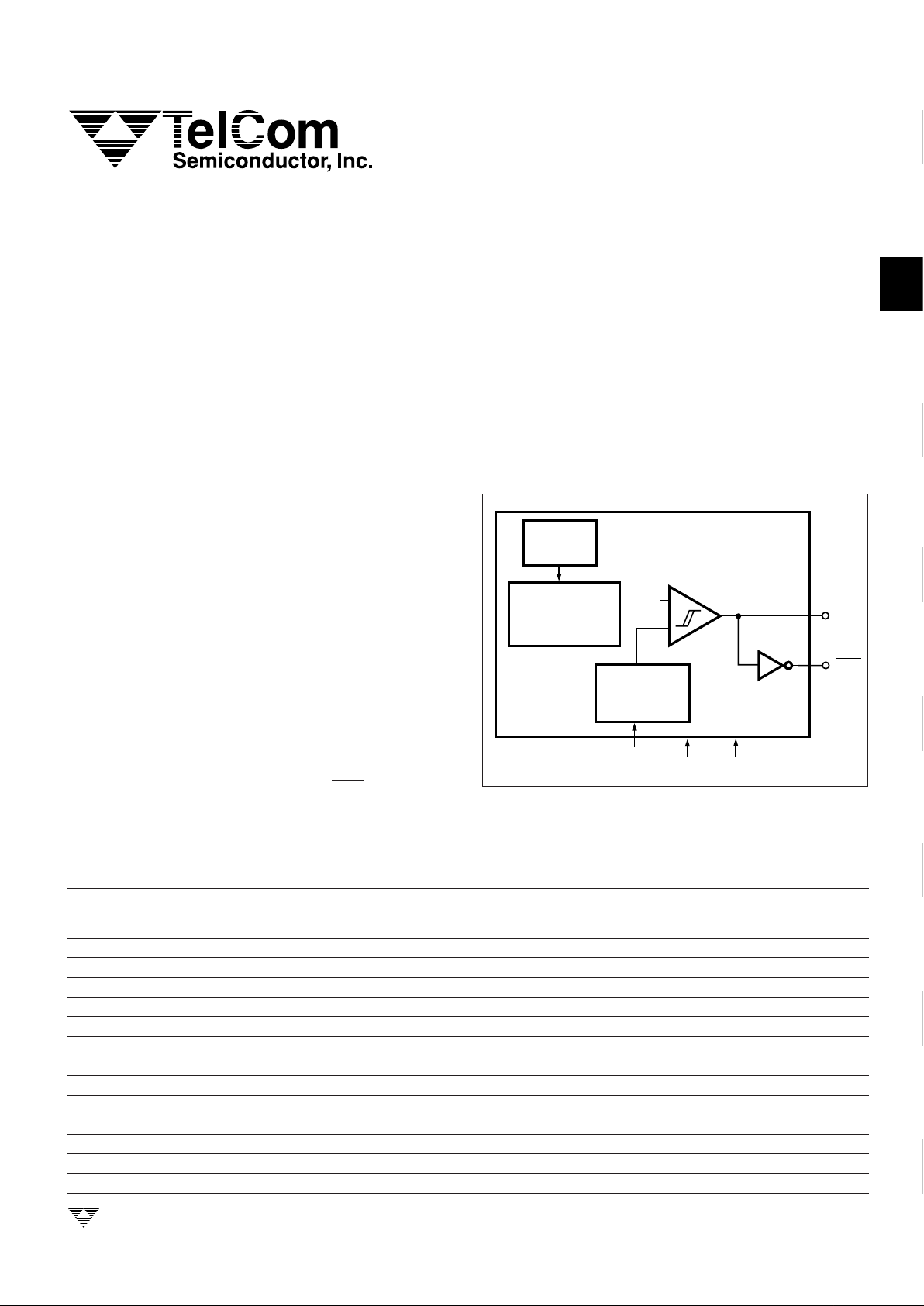
FUNCTIONAL BLOCK DIAGRAM
GENERAL DESCRIPTION
The TC622 and TC624 are programmable solid state
temperature switches designed to replace mechanical
switches in sensing and control applications. Both devices
integrate the temperature sensor along with a voltage reference and all required detector circuitry to form a stand-alone
temperature switch. The desired temperature set point is
set by the user with a single external resistor.
Ambient temperature is sensed and compared to the
programmed setpoint. The OUT and OUT outputs are
driven to their active state when the measured temperature
exceeds the programmed setpoint.
T
SET
V
DD
GND
OUT
OUT
TEMPERATURE
TO VOLTAGE
CONVERTER
VOLTAGE
REFERENCE
GENERATOR
TEMP
SENSOR
ORDERING INFORMATION
Part No. Voltage Operation Package Ambient Temperature
TC622COA 4.5V to 18V 8-Pin SOIC 0°C to +70°C
TC622CPA 4.5V to 18V 8-Pin Plastic DIP 0°C to +70°C
TC622EAT 4.5V to 18V 5-Pin TO-220 – 40°C to +85°C
TC622EOA 4.5V to 18V 8-Pin SOIC – 40°C to +85°C
TC622EPA 4.5V to 18V 8-Pin Plastic DIP – 40°C to +85°C
TC622VAT 4.5V to 18V 5-Pin TO-220 – 40°C to +125°C
TC622VOA 4.5V to 18V 8-Pin SOIC – 40°C to +125°C
TC622VPA 4.5V to 18V 8-Pin Plastic DIP – 40°C to +125°C
TC624COA 2.7V to 4.5V 8-Pin SOIC 0°C to +70°C
TC624CPA 2.7V to 4.5V 8-Pin Plastic DIP 0°C to +70°C
TC624EOA 2.7V to 4.5V 8-Pin SOIC – 40°C to +85°C
TC624EPA 2.7V to 4.5V 8-Pin Plastic DIP – 40°C to +85°C
TC624VOA 2.7V to 4.5V 8-Pin SOIC – 40°C to +125°C
TC624VPA 2.7V to 4.5V 8-Pin Plastic DIP – 40°C to +125°C
The TC622 has a power supply voltage range of 4.5V to
18.0V while the TC624 operates over a power supply range
of 2.7V to 4.5V. Both devices are usable over a temperature
range of – 40°C to +125°C (TC622Vxx, TC624Vxx). Both
devices feature low supply current making them suitable for
many portable applications.
Eight-pin through-hole and surface mount packages are
available. The TC622 is also offered in a 5-pin TO-220
package.
TC622/24-4 9/25/96
TC622
TC624

2-22
TELCOM SEMICONDUCTOR, INC.
ELECTRICAL CHARACTERISTICS (Over Operating Temperature Range, unless otherwise specified.)
Parameter Conditions Min Typ Max Unit
Supply Voltage Range TC622 4.5 — 18 V
TC624 2.7 4.5
Supply Current TC622 5.0V ≤ VDD ≤ 18V — 200 600 µA
TC624 2.7V ≤ VDD ≤ 4.5V — 170 300
V
OH
TC622 5.0V ≤ VDD ≤ 18V,
– 40°C ≤ T
A
≤ +125°C, I
OH
= 250µA 0.90 x V
DD
——V
I
OH
= 500µA 0.80 x V
DD
——
V
OL
TC622 – 40°C ≤ TA ≤ +85°C, IOL = 500µA
—
— 0.15 x V
DD
V
I
OL
= 1mA
—
— 0.30 x V
DD
– 40°C ≤ TA ≤ +125°C, IOL = 1mA
—
— 0.35 x V
DD
V
OH
TC624 2.7V ≤ VDD ≤ 4.5V,
– 40°C ≤ T
A
≤ +125°C, I
OH
= 250µA 0.9 x V
DD
——V
I
OH
= 500µA 0.8 x V
DD
——
V
OL
TC624 – 40°C ≤ TA ≤ +85°C, IOL = 500µA
—
— 0.1 x V
DD
V
I
OL
= 1mA
—
— 0.2 x V
DD
– 40°C ≤ TA ≤ +125°C, IOL = 1mA — — 0.25 x V
DD
Absolute Accuracy TC622 T
SET
= Programmed Temperature T – 5 T ± 1 T + 5 °C
TC624 T
SET
= Programmed Temperature T – 5 T ± 1 T + 5
Trip Point Hysteresis TC622 — 2 — °C
TC624 — 2 —
ABSOLUTE MAXIMUM RATINGS*
Supply Voltage (TC622).............................................20V
(TC624) ...........................................5.5V
Input Voltage Any Input.......(GND – 0.3V) to (VDD +0.3V)
Operating Temperature.........................– 40°C to +125°C
C Version...............................................0°C to +70°C
E Version ..........................................– 40°C to +85°C
V Version ........................................– 40°C to +125°C
Maximum Junction Temperature...........................+150°C
*Stresses above those listed under "Absolute Maximum Ratings" may
cause permanent damage to the device. These are stress ratings only and
functional operation of the device at these or any other conditions above
those indicated in the operation sections of the specifications is not implied.
Exposure to absolute maximum rating conditions for extended periods may
affect device reliability.
Storage Temperature ............................– 65°C to +150°C
Lead Temperature (Soldering, 10 sec) .................+300°C
The TC622 and TC624 are single point temperature
detectors ideal for use in a wide variety of applications.
When the temperature of the device exceeds the programmed temperature trip point, T
SET
, the OUT and OUT
outputs are driven into their active states. The desired trippoint temperature is programmed with a single external
resistor connected between the T
SET
input and VCC. The
relationship between the resistor value and the trip point
temperature is given by the equation below.
R
TRIP
= 0.5997 x T
2.1312
Where Rtrip = Programming resistor value in Ohms
T = Desired trip temperature in degrees Kelvin.
For example, to program the device to trip at 50°C,
the programming resistor is:
R
TRIP
= 0.5997 x ((50 + 273.15)
2.1312
) = 133,652 Ω
DETAILED DESCRIPTION
LOW COST, SINGLE TRIP POINT
TEMPERATURE SENSOR
TC622
TC624
 Loading...