

Datasheet TC621HCPA, TC621HEOA, TC621HCOA, TC621CEPA, TC621CCPA Datasheet (TelCom Semiconductor)
...
5V , DUAL TRIP POINT TEMPERA TURE SENSORS
1
TC620
TC621
FEATURES
■ User-Programmable Hysteresis and Temperature
Set Point
■ Easily Programs with 2 External Resistors
■ Wide Temperature Detection
Range................ – 40°C to +125°C (TC620/621CVx)
■ External Thermistor for Remote Sensing
Applications (TC621x)
APPLICATIONS
■ Power Supply Overtemperature Detection
■ Consumer Equipment
■ Temperature Regulators
■ CPU Thermal Protection
ORDERING INFORMATION
Ambient
Part No. Package Temperature
TC620x*COA 8-Pin SOIC 0°C to +70°C
TC620x*CPA 8-Pin Plastic DIP 0°C to +70°C
TC620x*EOA 8-Pin SOIC – 40°C to +85°C
TC620x*EPA 8-Pin Plastic DIP – 40°C to +85°C
TC620CVOA 8-Pin SOIC – 40°C to +125°C
TC621x*COA 8-Pin SOIC 0°C to +70°C
TC621x*CPA 8-Pin Plastic DIP 0°C to +70°C
GENERAL DESCRIPTION
The TC620 and TC621 are programmable logic output
temperature detectors designed for use in thermal management applications. The TC620 features an on-board temperature sensor, while the TC621 connects to an external
NTC thermistor for remote sensing applications.
Both devices feature dual thermal interrupt outputs
(HIGH LIMIT and LOW LIMIT), each of which program with
a single external resistor. On the TC620, these outputs are
driven active (high) when measured temperature equals the
user-programmed limits. The CONTROL (hysteresis) output is driven high when temperature equals the high limit
setting, and returns low when temperature falls below the
low limit setting. This output can be used to provide simple
ON/OFF control to a cooling fan or heater. The TC621
provides the same output functions except that the logical
states are inverted.
The TC620/621 are usable over a maximum temperature range of – 40°C to +125°C.
Ambient
Part No. Package Temperature
TC621x*EOA 8-Pin SOIC – 40°C to +85°C
TC621x*EPA 8-Pin Plastic DIP – 40°C to +85°C
*The part code will be C or H (see Functional Block Diagram, below,
and page 2).
2
3
4
5
FUNCTIONAL BLOCK DIAGRAM
Temp
to
Voltage
Converter
V
LOW SET
HIGH SET
2
3
REF
GEN
V
REF
V
REF
GEN
TELCOM SEMICONDUCTOR, INC.
TC620
+
–
+
–
R
Q
V
DD
8
Thermistor
1
4
7
LOW LIMIT
6
HIGH LIMIT
S
Q
5
CONTROL*
*Suffix code "C" denotes cooling option (high true CONTROL output);
suffix code "H" denotes heating option (low true CONTROL output).
THERMISTOR
HIGH SET
LOW SET
Interface
Circuit
V
2
GEN
V
3
V
GEN
REF
REF
REF
V
DD
8
TC621
+
–
4
7
HIGH LIMIT
6
7
+
–
R
Q
6
LOW LIMIT
S
Q
5
CONTROL*
8
TC620/1-9 11/4/96
2-15
TC620
TC621
5V , DUAL TRIP POINT
TEMPERATURE SENSORS
ABSOLUTE MAXIMUM RATINGS*
Maximum Chip Temperature.................................+150°C
Storage Temperature ............................– 65°C to +150°C
Package Power Dissipation (TA ≤ 70°C)
PDIP ...............................................................730mW
SOIC...............................................................470mW
Derating Factors
Plastic ............................................................8mW/°C
Supply Voltage ............................................................20V
Input Voltage Any Input....... (GND – 0.3V) to (VDD +0.3V)
Operating Temperature
M Version .......................................– 55°C to +125°C
Lead Temperature (Soldering, 10 sec) ................. +300°C
*Static-sensitive device. Unused devices must be stored in conductive
material. Protect devices from static discharge and static fields. Stresses
above those listed under "Absolute Maximum Ratings" may cause permanent damage to the device. These are stress ratings only and functional
operation of the device at these or any other conditions above those
indicated in the operation sections of the specifications is not implied.
Exposure to absolute maximum rating conditions for extended periods may
affect device reliability.
V Version ........................................– 40°C to +125°C
E Version ..........................................– 40°C to +85°C
C Version............................................... 0°C to +70°C
ELECTRICAL CHARACTERISTICS: T
= 25°C, unless otherwise specified.
A
Parameter Conditions Min Typ Max Unit
Supply Voltage Range 4.5 — 18 V
Supply Current 5V ≤ VDD ≤ 18V — 270 400 µA
Output Resistance Output High or Low, 5V ≤ VDD ≤ 18V — 400 1000 Ω
Output Current Temp Sensed Source/Sink — — 1 mA
Output Current Cool/Heat Source/Sink — — 1 mA
Absolute Accuracy T = Programmed Temperature T – 3 T T + 3 °C
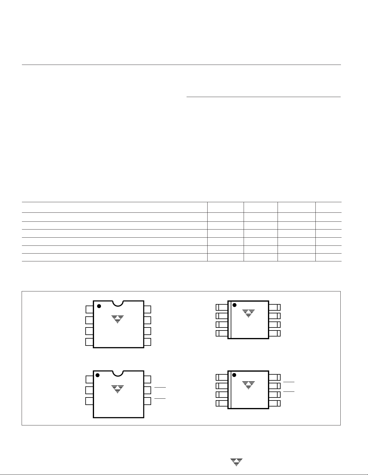
PIN CONFIGURATIONS (DIP and SOIC)
1
NC
GND
NC
GND
2
3
4
1
2
3
4
TC620xCPA
TC620xEPA
TC621xCPA
TC621xEPA
LOW SET
HIGH SET
HIGH SET
LOW SET
V
8
DD
LOW LIMIT
7
HIGH LIMIT
6
5
CONTROL
8
V
DD
HIGH LIMIT
7
6
LOW LIMIT
CONTROL
5
NC
LOW SET
HIGH SET
GND
NC
HIGH SET
LOW SET
GND
1
2
TC620xCOA
3
TC620xEOA
4
TC620CVOA
1
2
TC621xCOA
3
TC621xEOA
4
8
7
6
5
8
7
6
5
V
DD
LOW LIMIT
HIGH LIMIT
CONTROL
V
DD
HIGH LIMIT
LOW LIMIT
CONTROL
2-16
TELCOM SEMICONDUCTOR, INC.

5
SET POINT
(SET POINT – 2°C)
HIGH LIMIT
or LOW LIMIT
Output
5V , DUAL TRIP POINT
TEMPERATURE SENSORS
1
TC620
TC621
DETAILED DESCRIPTION
The TC620/621 consists of a positive temperature coefficient (PTC) temperature sensor, and a dual threshold
detector. Temperature setpoint programming is easily accomplished with external programming resistors from the
HIGH SET and LOW SET inputs to V
and LOW LIMIT outputs remain low as long as measured
temperature is below setpoint values. As measured temperature increases, the LOW LIMIT output is driven high
when temperature equals the LOW SET setpoint (±3°C
max). If temperature continues to climb, the HIGH LIMIT
output is driven high when temperature equals the HIGH
SET setpoint (Figure 1). The CONTROL (hysteresis) output
is latched in its active state at the temperature specified by
the HIGH SET resistor. CONTROL is maintained active until
temperature falls to the value specified by the LOW SET
resistor.
HIGH SET POINT
TEMPERATURE
LOW SET POINT
LOW LIMIT OUTPUT
HIGH LIMIT OUTPUT
CONTROL OUTPUT (COOL OPTION)
CONTROL OUTPUT (HEAT OPTION)
The HIGH LIMIT
DD.
Care must be taken to ensure the LOW SET programming resistor is a smaller value than the HIGH SET programming resistor. Failure to do this will result in erroneous
operation of the CONTROL output.
Care must also be taken to ensure the LOW SET
temperature setting is at least 5°C lower than the HIGH SET
temperature setting. That is:
LOW SET ≤ HIGH SET – 5°C
The nomograph of Figure 2 can help the user obtain an
estimate of the external resistor values required for the
desired LOW SET and HIGH SET trip points.
250
200
150
RESISTANCE (kΩ)
100
50
-55 -35 -15 5 25 45 65 85 105 12
TEMPERATURE (°C)
Figure 2. TC620 Sense Resistors vs. Trip Temperature
Built-in Hysteresis
2
3
4
5
Programming The TC620
temperatures on HIGH SET and LOW SET are calculated
using EQUATION 1 below:
LOW SET input is calculated using Equation 1 as follows:
Figure 1: TC620/621 Input vs. Output Logic
The resistor values to achieve the desired trip-point
R
= 0.5997 x T
TRIP
Where: Rtrip = Programming resistor in Ohms
T = The desired trip point temperature
For example, a 50°C setting on either the HIGH SET or
R
= 0.5997 x ((50 + 273.15)
set
TELCOM SEMICONDUCTOR, INC.
2.1312
in degrees Kelvin
Equation 1.
2.1312
) = 133.6k Ω
To prevent output "chattering" when measured temperature is at (or near) the programmed trip point values, the
LOW SET and HIGH SET inputs each have built-in hysteresis of – 2°C below the programmed settings (Figure 3).
6
7
Figure 3: Built-in Hysteresis on Low Limit and High Limit Outputs
As shown, the outputs remain in their active state
(hysteresis) until temperature falls an additional 2°C below
the user's setting.
8
2-17

TC620
TC621
5V , DUAL TRIP POINT
TEMPERATURE SENSORS
Using The TC621
The TC621 operation is identical to that of the TC620,
but requires an external NTC thermistor. Use the resistance
versus temperature curve of the thermistor to determine the
values of the programming resistors. Note that the pin
numbers for the HIGH SET and LOW SET programming
resistors for the TC621 are reversed versus that of the
TC620 (i.e. the resistor value on HIGH SET [pin 2] should
always be lower than the one connected to LOW SET [pin
3]). Also note that the outputs of the TC621 are LOW TRUE
when used with an NTC thermistor.
TC621 Thermistor Selection
The TC621 uses an external thermistor to monitor the
controlling temperature. A thermistor with a resistance value
of approximately 100kΩ at 25°C is recommended.
A temperature setpoint is selected by picking a resistor
whose value is equal to the resistance of the thermistor at the
desired temperature. For example, a 30kΩ resistor between
HIGH TEMP (pin 2) and VDD (pin 8) sets the high temperature trip point at +51°C and a 49kΩ resistor on LOW TEMP
(pin 3) sets the low temperature trip point to +41°C.
TC620/621 Outputs
Both devices have complimentary output stages. They
are rated at a source or sink current of 1mA maximum.
TYPICAL NTC THERMISTOR
APPLICATIONS
Dual Speed Temperature Control
The Dual Speed Temperature Control uses a TC620
and a TC4469 quad driver. Two of the drivers are configured
in a simple oscillator. When the temperature is below the
LOW TEMP set point, the output of the driver is OFF. When
the temperature exceeds the LOW TEMP set point, the
TC4469 gates the oscillator signal to the outputs of the
driver. This square wave signal modulates the remaining
outputs and drives the motor at a low speed. If this speed
cannot keep the temperature below the HIGH TEMP set
point, then the driver turns on continuously which increases
the fan speed to high. The TC620 will monitor the temperature and only allow the fan to operate when needed, and at
the required speed to maintain the desired temperature. A
higher power option can be designed by adding a resistor
and a power MOSFET.
Temperature Controlled Fan
In this application, a high and a low temperature is
selected by two ‘set’ resistors. The TC620 monitors the
ambient temperature and turns the FET switch on when the
temperature exceeds the HIGH TEMP set point. The fan
remains on until the temperature decreases to the LOW
TEMP set point. This provides the hysteresis. In this application, the fan turns on only when required.
The TC621 uses an external thermistor to monitor the
ambient temperature. This adds one part, but allows more
flexibility in location of the sensor.
350
300
250
200
150
100
THERMISTOR RESISTANCE (kΩ)
50
0
01020304050
TEMPERATURE (°C)
Figure 4. Typical Thermistor Resistance vs. Temperature
2-18
70
60
TELCOM SEMICONDUCTOR, INC.

TC620
HIGH TEMP
1
2
3
4
8
7
6
5
LOW TEMP
+12V
MTP3055E
FAN MOTOR
TC621
HIGH TEMP
1
2
3
4
8
7
6
5
LOW TEMP
+12V
MTP3055E
FAN MOTOR
THERMISTOR
(NTC)
5V , DUAL TRIP POINT
TEMPERATURE SENSORS
1
TC620
TC621
LOW TEMP
°
30 C
HIGH TEMP
°
50 C
TEMPERATURE SCALE
°
°
0 C
– 30 C (FAN OFF)
°
°
30 C
– 50 C (FAN LOW)
°
50 C
– UP (FAN HIGH)
2
3
1
5
8
TC620
4
6
7
1N4148
1N4148
1 µF
+12V
V
MOTOR
2
10 µF0.1 µF
14
10k
2
1
3
5
8
TC4469
Figure 5.
13
4
6
9
10
11
12
7
1M
100k
50 pF
FAN MOTOR
50Ω
HIGHER POWER OPTION
FAN MOTOR
MOSFET
3
4
5
Figure 6.
6
4.5V TO 18V
HIGH
TEMP
LOW
TEMP
1
2
3
TC620
4
Figure 7. TC620 Heating/Cooling Application
8
7
6
5
1
2
3
4
TC4469
5
6
7
14
13
12
11
10
9
8
1k
1k
HIGH
TEMP
WARNING
HEATING/COOLING
EQUIPMENT
LOW
TEMP
WARNING
7
8
TELCOM SEMICONDUCTOR, INC.
2-19

TC620
TC621
5V , DUAL TRIP POINT
TEMPERATURE SENSORS
4.5V TO 18V
HIGH
TEMP
LOW
TEMP
1
2
3
TC620
4
8
7
6
5
Figure 8. TC620 Heating/Cooling Application
1
2
3
4
5
6
7
TC4469
14
13
12
11
10
9
8
1k
1k
HIGH
TEMP
WARNING
HEATING/COOLING
EQUIPMENT
LOW
TEMP
WARNING
2-20
TELCOM SEMICONDUCTOR, INC.
 Loading...