

LINEAR BUILDING BLOCK –
PRELIMINARY INFORMATION
VOL TAGE REFERENCE, DUAL OP AMP,
DUAL COMPARATOR WITH SHUTDOWN MODE
EVALUATION
KIT
AVAILABLE
TC43
TC43
LINEAR BUILDING BLOCK – VOL TAGE REFERENCE, DUAL OP AMP,
DUAL COMPARATOR WITH SHUTDOWN MODE
FEATURES
■ Combines Two Op Amps, Two Comparators and a
Voltage Reference into a Single Package
■ Optimized for Single Supply Operation
■ Small Package .......... 16-Pin SOIC or DIP (Narrow)
■ Ultra Low Input Bias Current ...... Less than 100pA
■ Low Quiescent
Current.....................10µA, 5µA in Shutdown Mode
■ Reference and One Comparator Remain Active in
Shutdown to Provide Supervisory Functions
APPLICATIONS
■ Power Supply Circuits
■ Embedded Systems
■ Instrumentation
■ Portable Equipment
■ Consumer Products
■ Replacements for Discrete Components
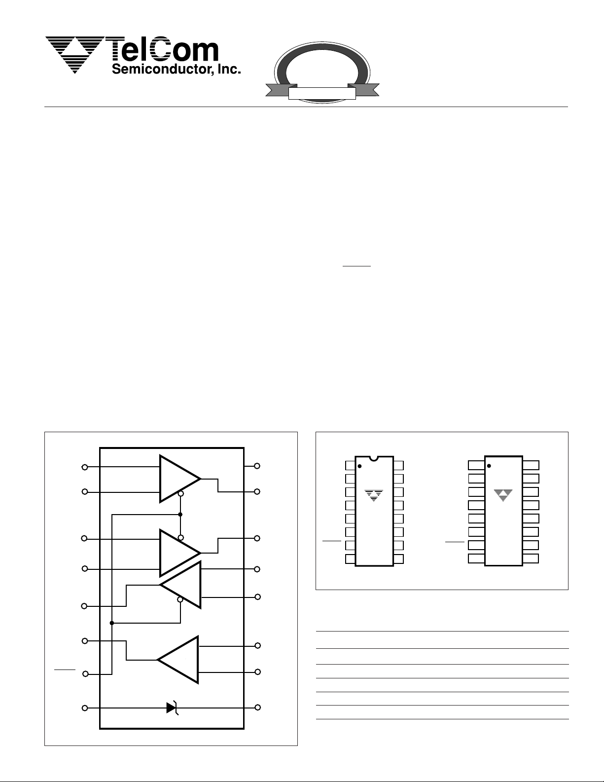
FUNCTIONAL BLOCK DIAGRAM
C1
A1
A1
A2
A2
IN
IN
IN
IN
OUT
+
–
+
–
+
AMP 1
–
+
AMP 2
–
CMPTR 1
+
–
V
A1
A2
C1
C1
DD
OUT
OUT
IN
IN
+
–
GENERAL DESCRIPTION
The TC43 is a mixed-function device combining two
general purpose op amps, two general purpose comparators and a voltage reference in a single 16-pin package.
This increased integration allows the user to replace
two or three packages, saving space, lowering supply
current, and increasing system performance. A Shutdown
input, SHDN, disables the op amps and one of the comparators, placing their outputs in a high-impedance state. The
reference and one comparator stay active in Shutdown
Mode. Standby power consumption is typically 5µA.
The TC43 is designed specifically for operation from a
single supply, however, operation from dual supplies is also
possible, and the power supply current drain is independent
of the magnitude of the power supply voltage.
Packaged in a 16-pin narrow SOIC (0.150 wide) or
16-pin DIP, the TC43 is ideal for applications requiring high
integration, small size and low power.
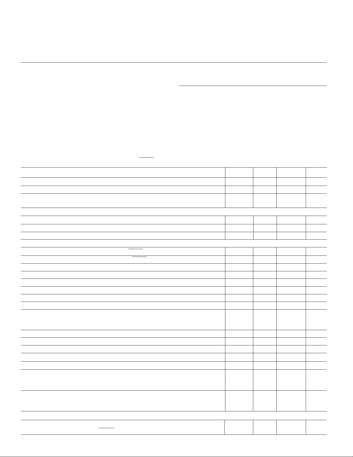
PIN CONFIGURATIONS (DIP and SOIC)
A1
A1
A2
A2
C1
OUT
C2
OUT
SHDN
V
+
1
IN
–
2
IN
+
IN
3
–
IN
4
TC43CPR
TC43EPR
5
6
7
8
SS
16
15
14
13
12
11
10
V
DD
A1
OUT
A2
OUT
C1
IN
C1
IN
C2
IN
C2
IN
V
9
REF
A1
1
+
IN
A1
2
–
IN
A2
+
3
IN
A2
–
4
C1
OUT
C2
OUT
SHDN
V
IN
SS
5
6
7
8
TC43COR
TC43EOR
+
–
+
–
16
15
14
13
12
11
10
V
DD
A1
OUT
A2
OUT
C1
+
IN
C1
–
IN
C2
+
IN
C2
–
IN
V
9
REF
ORDERING INFORMATION
C2
OUT
SHDN
+
CMPTR 2
–
C2
C2
+
IN
–
IN
Part No. Package Temp. Range
TC43COR 16-Pin SOIC (Narrow) 0°C to +70°C
TC43CPR 16-Pin Plastic DIP (Narrow) 0°C to +70°C
TC43EOR 16-Pin SOIC (Narrow) – 40°C to +85°C
V
SS
TC43-1 3/12/97 TelCom Semiconductor reserves the right to make changes in the circuitry and specifications of its devices.
V
REF
+
TC43EPR 16-Pin Plastic DIP (Narrow) – 40°C to +85°C
TC43EV Evaluation Kit for TC43
1
PRELIMINARY INFORMATION
TC43
LINEAR BUILDING BLOCK –
VOL TAGE REFERENCE, DUAL OP AMP,
DUAL COMP ARATOR WITH SHUTDOWN MODE
ABSOLUTE MAXIMUM RATINGS*
Supply Voltage ..............................................................6V
Package Power Dissipation (
PDIP ..............................................................840mW
SOIC (Narrow)................................................700mW
Voltage on Any Pin:
(With Respect to GND)........
Operating Temperature Range:
C Suffix ................................................. 0°C to +70°C
TA ≤ 70°C)
(V
SS
– 0.3V) to (VDD +0.3V)
Storage Temperature Range ................– 65°C to +150°C
Lead Temperature (Soldering, 10 sec) .................+300°C
* Static-sensitive device. Unused devices must be stored in conductive
material. Protect devices from static discharge and static fields. Stresses
above those listed under Absolute Maximum Ratings may cause permanent damage to the device. These are stress ratings only and functional
operation of the device at these or any other conditions above those
indicated in the operational sections of the specifications is not implied.
Exposure to Absolute Maximum Rating Conditions for extended periods
may affect device reliability.
E Suffix ............................................– 40°C to + 85°C
ELECTRICAL CHARACTERISTICS: T
= Over Operating Temperature Range, V
A
= 5.0V ±10%, V
DD
SS
= 0V,
SHDN = VDD, unless otherwise specified.
Symbol Parameter Test Conditions Min Typ Max Unit
V
DD
I
Q
I
SHDN
Supply Voltage 1.8 — 5.5 V
Supply Current, Operating All Outputs Open — 10 15 µA
Supply Current, Shutdown Mode All Outputs Open — 5 8 µA
(Note 1)
Shutdown Input
V
IH
V
IL
I
IL
Input High Voltage 80% V
DD
Input Low Voltage — — 20% V
——V
DD
V
Input Current — — 1 µA
Op Amps
T
SEL
T
DESEL
A
VOL
V
ICMR
V
OS
I
B
V
OS (DRIFT)
GBWP Gain-Bandwidth Product 4 7 — kHz
SR Slew Rate Gain = 1, VIN = 4.0
V
OUT
CMRR Common Mode Rejection Ratio — 80 — dB
PSRR Power Supply Rejection Ratio (4.5V to 5.5V) — 80 — dB
R
(SD) Output Resistance in Shutdown SHDN = V
OUT
C
(SD) Output Capacitance in Shutdown SHDN = V
OUT
I
SRC
I
SINK
Select Time (V
from SHDN = VIH) — 2 — msec
OUT
Deselect Time (HI-Z from SHDN = VIL)—5—µsec
Large Signal Voltage Gain
Common Mode Input Voltage Range 1.8 < VDD < 5.5V V
CL = 100pF, RL = 47kΩ
— 100 — dB
SS
—VDD – 1.0 V
Input Offset Voltage VCM = (VDD – VSS)/2 –10 ±1.0 +10 mV
Input Bias Current — 50 — pA
Average Input Offset Voltage Drift — 30 — µV/°C
— 2 — V/msec
= 100pF, RL = 1MΩ
C
L
to V
SS
P-P
Output Signal Swing RL = 47kΩ VSS + .20 — VDD – .15 V
20 — — MΩ
3820mA
DC Output Source Current VIN = V
Output Shorted to V
SS
(Note 5) — 40 55 pF
SS
DD
SS
(Note 2)
DC Output Sink Current VIN = V
Output Shorted to V
SS
DD
0.6 1.2 5 mA
(Note 2)
Comparators
T
SEL
CMPTR1 Select Time — 5 — µsec
(V
from SHDN = VIH)
OUT
2

LINEAR BUILDING BLOCK –
VOL TAGE REFERENCE, DUAL OP AMP,
DUAL COMPARATOR WITH SHUTDOWN MODE
PRELIMINARY INFORMATION
TC43
ELECTRICAL CHARACTERISTICS: (Cont.) T
V
= Over Operating Temperature Range, V
A
= 0V, SHDN = VDD, unless otherwise specified.
SS
= 5.0V ±10%,
DD
Symbol Parameter Test Conditions Min Typ Max Unit
Comparators (Cont.)
T
DESEL
V
IN
V
IN(CM)
V
OS
I
B
V
OH
V
OL
I
OH
I
OL
t
PD1
t
PD2
R
(SD) Output Resistance in Shutdown SHDN = V
OUT
C
(SD) Output Capacitance in Shutdown SHDN = V
OUT
CMPTR1 Deselect time — 5 — µsec
(HI-Z from SHDN = VIL)
Differential Input Voltage Range Both VINs > = V
Input Common Mode Voltage Range
Note 3, 5 V
SS
——VDDV
SS
—VDDV
Input Offset Voltage VCM = (VDD – VSS)/2 – 10 — +10 mVDC
Input Bias Current IN+ or IN
Output High Voltage RL = 10kΩ to VSS,V
–
—50— pA
– 0.3 — — V
DD
1.8 < VDD < 5.5V
Output Low Voltage RL = 10kΩ to V
DD
— — 0.3 V
1.8 < VDD < 5.5V
Output Source Current
(Continuous) V
Output Sink Current
(Continuous) V
Response Time
VIN (+) = VDD, VIN (–) = V
= 1.8V, Output
DD
Shorted to V
SS
VIN (–) = VDD, VIN (+) = V
= 1.8V, Output
DD
Shorted to V
DD
SS
SS
100mV Overdrive (Note 4)
1.3 3 8 mA
2.5 6 15 mA
—15—µsec
Response Time 10mV Overdrive (Note 4) — 60 — µsec
SS
(Note 5) — 3 5 pF
SS
20 — — MΩ
Voltage Reference
V
REF
C
L(REF)
N
VREF
NOTES: 1. The reference and one comparator remain active in SHUTDOWN mode.
2. Op Amp configured as a voltage follower (inverting input connected to output; signal applied to non-inverting input).
3. Input common-mode voltage should not be allowed to go negative by more than 0.3V.
4. VDD = 5.0V; CL = 100pF.
5. Guaranteed by Design
Reference Voltage No Load 1.152 1.200 1.248 V
Load Regulation
0mA < I
SOURCE <
5mA — – 300 — µV/mA
VDD = 5V, TA = 25°C
Load Capacitance — — 100 pF
Voltage Noise 100Hz to 100kHz — 100 — µV
RMS
DETAILED DESCRIPTION
The TC43 is the first of a series of very low power, Linear
Building Block products targeted at low voltage, single
supply applications. The TC43 minimum operating voltage
is 1.8V and maximum supply current is only 15µA (fully
enabled). It combines two comparators, two op amps and a
voltage reference in a single package. A shutdown mode is
incorporated for easy adaptation to system power management schemes. During shutdown, all but one comparator
and the voltage reference are disabled (i.e. powered down
and with their respective outputs at high impedance). The
“still awake” comparator and voltage reference can be used
as wake-up timer, power supply monitor, LDO controller or
other continuous duty circuit function.
Operational Amplifiers
Both op amps have rail-to-rail outputs, and an input
common range that includes ground. Input offset voltage is
1.0mV and input bias current is only 50pA. The outputs are
protected against short circuits. Both op amps are disabled
(powered down and outputs at high impedance) during
shutdown.
Comparators
Both comparators feature complimentary outputs with
current sinking capability of 2.5mA. Inputs and outputs are
rail-to-rail. Comparator CMPTR1 is disabled (powered down
and outputs at high impedance) during shutdown. CMPTR2
remains fully enabled during shutdown.
3

PRELIMINARY INFORMATION
TC43
LINEAR BUILDING BLOCK –
VOL TAGE REFERENCE, DUAL OP AMP,
DUAL COMP ARATOR WITH SHUTDOWN MODE
Voltage Reference
A 4% tolerance, internally biased, 1.20V bandgap voltage reference is included in the TC43. It has a push-pull
output capable of sourcing 5mA or sinking 200µA. The
voltage reference remains fully enabled during shutdown.
Shutdown Input
SHDN at VIL disables both op amps and one comparator. The SHDN input cannot be allowed to float; when not
used, connect to VDD.
TYPICAL APPLICATIONS
The TC43 lends itself to a wide variety of applications,
particularly in battery-powered systems. It typically finds
application in power management, processor supervisory,
and interface circuitry.
Wake-up Timer
Many microcontrollers have a low power “sleep” mode
that significantly reduces their supply current. Typically, the
microcontroller is placed in this mode via a software instruction, and returns to a fully enabled state upon reception of
an external signal (“wake-up”). The wake-up signal is usually supplied by a hardware timer. Most system applications
demand that this timer have a long duration (typically
seconds or minutes), and consume as little supply current
as possible.
The circuit shown in Figure 1 is a wake-up timer made
from comparator CMPTR2. (CMPTR2 is used because the
wake-up timer must operate when SHDN is active.) Capaci-
MICROCONTROLLER
I/O*
WAKE-UP
R1
5M
C1
10µF
R4
V
DD
CMPTR2
–
+
tor C1 charges through R1 until a voltage equal to
VDD/2 is reached, at which point the WAKE is driven active.
Upon wake-up, the microcontroller resets the timer by
forcing a logic low on a dedicated, open drain I/O port pin.
This discharges C1 through R4 (the value of R4 is chosen to
limit maximum current sunk by the I/O port pin). With a 3V
supply, the circuit as shown consumes typically 8µA and
furnishes a nominal timer duration of 25 seconds.
Precision Battery Monitor
Figure 2 is a precision battery low/battery dead monitoring circuit. Typically, the battery low output warns the user
that a battery dead condition is eminent. Battery dead
typically initiates a forced shutdown to prevent operation at
low internal supply voltages (which can cause unstable
system operation).
The circuit of Figure 2 uses a single TC43 (one Op Amp
unused) and only 7 external resistors. AMP 1 is a simple
buffer while CMPTR1 and CMPTR2 provide precision voltage detection using Vr as a reference. Resistors R2 and R4
set the detection threshold for BATT LOW while resistors
R1 and R7 set the detection threshold for BATT FAIL. The
component values shown assert BATT LOW at 2.2V (typical) and BATT FAIL at 2.0V (typical). Total current consumed by this circuit is typically 22µA at 3V.
DUAL LDO with Shutdown
Figure 3 shows a portion of a TC43 configured as a dual
low drop regulator with shutdown. AMP1 and AMP2 are
independent error amplifiers that use Vr as a reference.
Resistors RA and RB set the feedback around the amplifier
and therefore determine the output voltage setting (please
see equation in the figure). RA and RB can have large ohmic
values (i.e. 100’s of KΩ) to minimize supply current.
Using the 2N2222 output transistors as shown, these
regulators exhibit low dropout operation. For example, with
V
= 3.0V, the typical drop out voltage is only 50mV at an
OUT
output current of 50mA. The unused comparators can be
used in conjunction with this circuit as power-on reset or low
voltage detectors for a complete LDO solution at a very low
installed cost.
EVALUATION KIT
R2, 1M
R3, 1M
Figure 1. Wake-Up Timer
*OPEN DRAIN PORT PIN
The TC43EV consists of a four inch by six inch pre-wired
application circuit board. Pre-configured circuits include a
pulse width modulator, wake-up timer, function generator,
and others. On-board current meter terminals, voltage regulator and a user-prototyping area speed circuit development. Please contact your local TelCom Semiconductor
representative for more information.
4

LINEAR BUILDING BLOCK –
VOL TAGE REFERENCE, DUAL OP AMP,
DUAL COMPARATOR WITH SHUTDOWN MODE
PRELIMINARY INFORMATION
TC43
3V
ALKALINE
+
AMP1
–
TC43
TO SYSTEM DC/DC
CONVERTER
R2, 330k, 1%
R1, 270k, 1%
R4, 470k, 1%
Vr
R5, 7.5M
+
CMPTR1
–
+5V
–
CMPTR2
+
R6, 7.5M
R3, 470k, 1%
BATTLOW
BATTFAIL
Vr
+
AMP1
–
V
= Vr x (RA + RB)/RB
OUT
Figure 2. Precision Battery Monitor
V
IN
2N2222
V
OUT1
RA
RB
C1, 1µF
TC43
+
AMP2
–
RA
RB
2N2222
SHDN
V
OUT2
C2, 1µF
Figure 3. Dual Low Dropout Regulator
5

PRELIMINARY INFORMATION
TC43
PACKAGE DIMENSIONS
LINEAR BUILDING BLOCK –
VOL TAGE REFERENCE, DUAL OP AMP,
DUAL COMP ARATOR WITH SHUTDOWN MODE
16-Pin Plastic DIP (Narrow)
.200 (5.08)
.140 (3.56)
.150 (3.81)
.115 (2.92)
.110 (2.79)
.090 (2.29)
16-Pin SOIC (Narrow)
.770 (19.56)
.745 (18.92)
.070 (1.78)
.045 (1.14)
.022 (0.56)
.015 (0.38)
PIN 1
PIN 1
.260 (6.60)
.240 (6.10)
.040 (1.02)
.020 (0.51)
.015 (0.38)
.008 (0.20)
.310 (.787)
.290 (.737)
3° MIN.
.400 (10.16)
.310 (7.87)
.050 (1.27) TYP
.018 (0.46)
.014 (0.36)
Sales Offices
TelCom Semiconductor
1300 Terra Bella Avenue
P.O. Box 7267
Mountain View, CA 94039-7267
TEL: 415-968-9241
FAX: 415-967-1590
E-Mail: liter@c2smtp.telcom-semi.com
.394 (10.00)
.385 (9.78)
.157 (3.99)
.150 (3.81)
.010 (0.25)
.004 (0.10)
TelCom Semiconductor
Austin Product Center
9101 Burnet Rd. Suite 214
Austin, TX 78758
TEL: 512-873-7100
FAX: 512-873-8236
.244 (6.20)
.228 (5.79)
.069 (1.75)
.053 (1.35)
6
8°
MAX.
.050 (1.27)
.016 (0.40)
.010 (0.25)
.007 (0.18)
Dimensions: inches (mm)
TelCom Semiconductor H.K. Ltd.
10 Sam Chuk Street, Ground Floor
San Po Kong, Kowloon
Hong Kong
TEL: 852-2324-0122
FAX: 852-2354-9957
Printed in the U.S.A.
 Loading...