

Telcoma Automations EVO600, EVO600SC, EVO800, ACE500ET, ACE800E Instruction Manual And Spare Parts Catalogue
...
ISTEVO
Telcoma srl - Via L. Manzoni, 11 - Z.I. Campidui - 31015 Conegliano - (TV) Italy
Tel. +39 0438-451099 - Fax +39 0438-451102 - Part. IVA 00809520265
http://www.telcoma.it E-mail: info@telcoma .it
MOTORIDUTTORI ELETTROMECCANICI PER CANCELLI SCORREVOLI
MANUALE ISTRUZIONI E CATALOGO RICAMBI
I
OPÉRATEURS ÉLECTROMÉCANIQUES POUR PORTAILS COULISSANTS
NOTICE D'INSTRUCTIONS ET CATALOGUE DES PIÈCES DE RECHANGE
F
MOTORREDUCTORES ELECTROMECÁNICOS PARA CANCELAS CORREDERAS
MANUAL DE INSTRUCCIONES Y CATÁLOGO DE PIEZAS DE REPUESTO
E
ELECTROMECHANICAL GEARMOTORS FOR SLIDING GATES
INSTRUCTIONS MANUAL AND SPARE PARTS CATALOGUE
GB
ELEKTROMECHANISCHE SCHIEBETORANTRIEBE
BEDIENUNGSANLEITUNG UND ERSATZTEILKATALOG
D
ELEKTROMECHANISCHE REDUCTIEMOTOREN VOOR SCHUIFPOORTEN
GEBRUIKERSHANDLEIDING EN ONDERDELENCATALOGUS
NL
EVO
ACE500ET-ACE800E
V. 03.2009
INFORMAZIONI GENERALI
I F E
2
I motoriduttori della serie EVO e ACE500ET ACE800E offrono un'ampia versatilità per
l'automazione di cancelli scorrevoli grazie alla
gamma di potenze, alle regolazioni di altezza e
profondità,aidispositividisicurezzainclusi.
Infatti, nei motori completi di centralina
elettronica, sono presenti dei sensori encoder
perlarilevazionedegliostacoli.
Per una sicura e corretta installazione vi
chiediamo, quindi, di leggere attentamente le
presenti istruzioni prestando particolare
attenzione al capitolo “AVVERTENZE
IMPORTANTI SULL'INSTALLAZIONE” e in
seguito di conservarle per una futura
consultazione.
Um EVO600 EVO600SC EVO800 EVO1200 ACE800E
Vac 230 230 230 230
230
V 230Vac 230Vac 230Vac 230Vac
24Vdc
Kg 600 600 800 1200
800
N 540 540 640 1200 640
A 3,4 3,4 3,4 5,2
VA 800 800 800 1100
μF 16 16 20 20
-
SI/YES SI/YES SI/YES
SI/YES
SI/YES - SI/YES SI/YES SI/YES
Nm 21 21 24 45
24
m/min 10 10 10 10
11
°C -20+70 -20+70 -20+70 -20+70 -20+70
°C 150 150 150 150
-
IP
40 60 60
Kg 13 13 15 17
SI/YES - SI/YES SI/YES
SI/YES
- SI/YES - -
-
F F
TS 10 TS 10 - - TS10
- - TS 20 TS 40 -
F F
DATI TECNICI
Tensione di alimentazione
Alimentazione motore
Peso max cancello
Forza di spinta
Corrente max assorbita
Potenza max assorbita
Condensatore
Classe di isolamento
Lubrificante grasso
Lubrificante olio
Coppia nominale
Velocità cancello
Temp. di funzionamento
Intervento termoprotezione
Grado di protezione
Encoder
Intermittenza lavoro
Peso
Finecorsa elettronico
Finecorsa meccanico
Centrale elettronica incorporata
INFORMATIONS GÉNÉRALES
Les opérateurs de la série EVO et
offrent une grande flexibilité pour
l'automatisation de portails coulissants grâce à
la gamme de puissances, aux réglages de
hauteur et profondeur, aux dispositifs de
sécuritéinclus.
En effet, les moteurs avec logique de
commande électronique sont équipés de
capteurs à encodeur pour la détection des
obstacles.
Pour une installationsûreetcorrecte,nous vous
prions donc de lire attentivement ces
instructionsen faisant particulièrement attention
au chapitre « RECOMMAND ATIONS
IMPORTANTES POUR L'INSTALLATION » et
delesconserverpourtouteconsultationfuture.
ACE500ET -
ACE800E
INFORMACIONES GENERALES
Los motorreductores de la serie EVO y
ofrecen una amplia
versatilidad para la automatización de
cancelas correderas gracias a la gama de
potencias, a las regulaciones de altura y
profundidad y a los dispositivos de seguridad
incluidos.
En efecto, en los motores equipados con
central electrónica, se encuentran presentes
sensores codificadores para la detección de
losobstáculos.
Para llevar a cabo una instalación segura y
correcta le rogamos, por lo tanto, que lea
atentamente las presentes instrucciones
prestando una atención particular al capítulo
“ADVERTENCIAS IMPORTANTES SOBRE
LA INSTALACIÓN” y que las conserve para
unaconsultafutura.
ACE500ET - ACE800E
DONNÉES TECHNIQUES
Tension d'alimentation
Alimentation moteur
Poids max. portail
Force de poussée
Courant max. absorbé
Puissance max. absorbée
Condensateur
Logique électronique incorporée
Classe d'isolement
Lubrifiant graisse
Lubrifiant huile
Couple nominal
Vitesse portail
Température de fonctionnement
Intervention protection thermique
Indice de protection
Encodeur
Intermittence travail
Poids
Fin de course électronique
Fin de course mécanique
DATOS TÉCNICOS
Tensión de alimentación
Alimentación motor
Peso máx cancela
Fuerza de empuje
Corriente máx absorbida
Potencia máx absorbida
Condensator
Central electrónica incorporada
Clase de aislamiento
Lubrificante grasa
Lubrificante aceite
Par nominal
Velocidad cancela
Temp. de funcionamiento
Intervención termoprotección
Grado de protección
Encoder
Intermitencia trabajo
Peso
Fin de carrera electrónico
Fin de carrera mecánico
ACE500ET
230
24Vdc
500
500
-
18
11
-20+70
-
SI/YES
SI/YES
-
SI/YES
-
TS10
-
F
1,5
200
12
2,2
300
13
% 40
54 54 54 54 54
54
SI/YES
60
60
GB D NL
3
GENERAL INFORMATION
The EVO and series
gearmotors offer ample flexibility for the
automation of sliding gates thanks to the range
of powers, height and depth adjustment and
includedsafetydevices.
In fact, the motor with electronic control unit
includes encoder sensors for obstacle
detection.
Therefore, in order that the installation is
performed in a safe and correct manner, we
kindly ask you to carefully read the present
instructions giving particularattentionto chapter
“IMPORTANT INSTALLATION WARNINGS"
and tokeepthese instructions inasafe place for
futurereference.
ACE500ET - ACE800E
ALLGEMEINE AUSKÜNFTE
Die Antriebe der Serien EVO und
bieten dank den verschiedenen
Leistungen,denHöhen-undTiefenverstellungen
u n d d e n e i n g e s c h l o s s e n e n
Sic her hei tsv orr ich tun gen ein e g roß e
Vielseitigkeit bei der Automatisierung von
Schiebetoren.
Die mit elektronischer Steuerung ausgestatteten
Antriebe verfügen über Encodersensoren zur
Wahrnehmungder Hindernisse.
Für eine sichere und korrekte Installation bitten
wir Sie daher, die vorliegenden Anweisungen
und insbesondere das Kapitel „WICHTIGE
HINWEISE ZUR INSTALLATION „aufmerksam
zu lesen und sie dann für ein zukünftiges
Nachschlagenaufzubewahren.
ACE500ET -
ACE800E
ALGEMENE INFORMATIE
De reductiemotoren uit de serie EVO en
zijnuitermateveelzijdig
voor het automatiseren van schuifpoorten
dankzijeen heelscalaaanvermogen,afstelling
in hoogte en diepte, veiligheidsinrichtingen
inbegrepen.
In de motoren voorzien van een elektronische
best ur in gs ee nh ei d, b evind en z ich
encodersensorenvoorobstakeldetectie.
Voor een veilige en correcte installatie
verzoeken wij u daarom deze aanwijzingen
aandachtigdoortelezeneninhetbijzonder het
hoofdstuk “BELANGRIJKE AANWIJZINGEN
VOOR HET INSTALLEREN” en ze daarna te
bewaren om ze in de toekomst te kunnen
raadplegen.
ACE500ET-ACE800E
TECHNICAL SPECIFICATIONS
Power Supply voltage
Motor power supply
Max. gate weight
Thrust force
Max. absorbed current
Max absorbed power
Capacitor
Incorporatedelectroniccontrolunit
Insulation class
Grease lubricant
Oil lubricant
Nominal torque
Gate speed
Operating time
Thermal cut-out
Protection class
Encoder
Operating intervals
Weight
Electronic limit switch
Mechanical stop
TECHNISCHE DATEN
Spannungsversorgung
Motorversorgung
Höchstgewicht des Tors
Schubkraft
Max. Stromaufnahme
Max. Leistungsaufnahme
Kondensator
EingebauteelektronischeSteuerung
Isolationsklasse
Fettschmierung
Ölschmierung
Nenndrehmoment
Torgeschwindigkeit
Betriebstemp.
Auslösung des Wärmeschutzes
Schutzart
Encoder
Betriebsintermittenz
Gewicht
Elektronischer Endschalter
Mechanischer Endschalter
TECHNISCHE GEGEVENS
Spanning stroomvoorziening
Stroomvoorziening motor
Max gewicht poort
Duwkracht
Mas opgenomen stroom
Max opgenomen vermogen
Condensator
Ingebouwde besturingseenheid
Isoleringsklasse
Smeermiddel vet
Smeermiddel olie
Nominale koppel
Snelheid poort
Bedrijfstemp
Inwerkingtredingoververhittingsbeveiliging
Beschermingsklasse
Encoder
Onderbreking bedrijf
Gewicht
Elektronische eindschakelaar
Mechanische eindaanslag
Um EVO600 EVO600SC EVO800 EVO1200
ACE800E
Vac 230 230 230 230
230
V 230Vac 230Vac 230Vac 230Vac
24Vdc
Kg 600 600 800 1200
800
N 540 540 640 1200 640
A 3,4 3,4 3,4 5,2
VA 800 800 800 1100
μF 16 16 20 20
-
SI/YES SI/YES SI/YES SI/YES
SI/YES - SI/YES SI/YES
SI/YES
Nm 21 21 24 45
24
m/min 10 10 10 10 11
°C -20+70 -20+70 -20+70 -20+70
-20+70
°C 150 150 150 150
-
IP
% 40 40 60 60
Kg 13 13 15 17
SI/YES - SI/YES SI/YES
SI/YES
- SI/YES - -
-
F F
TS 10 TS 10 - -
TS10
- - TS 20 TS 40 -
F F
ACE500ET
230
24Vdc
500
500
-
18
11
-20+70
-
SI/YES
SI/YES
-
SI/YES
-
TS10
-
F
1,5
200
12
2,2
300
13
54 54 54 54 54
54
SI/YES
60
60
4
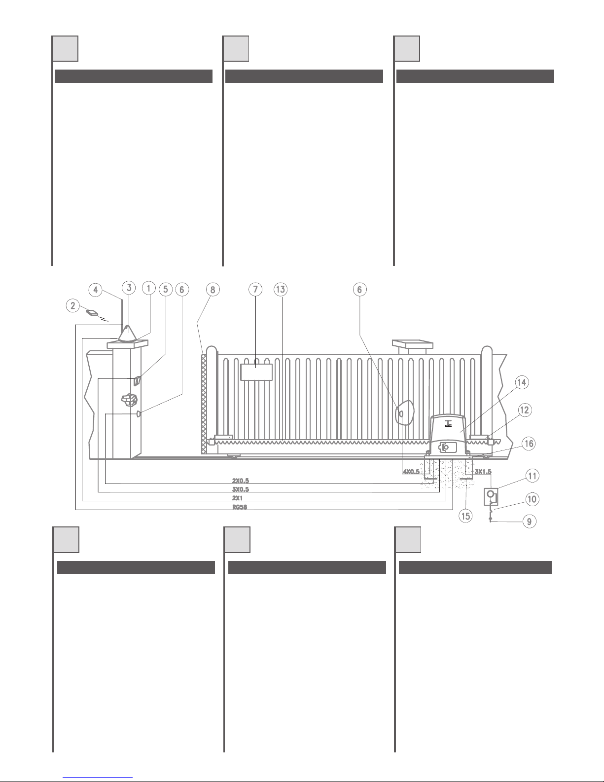
QUADRO D'INSIEME
E
1.Supportoperlampeggiatore+antenna
2.Radiocomando
3.Lampeggiatore
4.Antenna
5.Selettore
6.Fotocellula
7.Cartellodiavvertenza
8.Bordoingomma
9.Lineadialimentazione
10.Interruttoregenerale
11.Interruttoredifferenziale
12.Magnetedifinecorsa
13.Cremagliera
14.Motoriduttore
15.Contropiastradifondazione(optional)
16.Piastradifissaggio
VUE D'ENSEMBLE
1.Supportpourclignotant+antenne
2.Radiocommande
3.Clignotant
4.Antenne
5.Sélecteur
6.Photocellule
7.Panneaudesignalisation
8.Bordencaoutchouc
9.Ligned'alimentation
10.Interrupteurgénéral
11.Interrupteurdifférentiel
12.Aimantdefindecourse
13.Crémaillère
14.Opérateur
15.Contre-plaquedefondation(option)
16.Plaquedefixation
VISIÓN DE CONJUNTO
1.Soporteparaluzintermitente+antena
2.Radiocontrol
3.Luzintermitente
4.Antena
5.Selector
6.Fotocélula
7.Carteldeadvertencia
8.Bordedegoma
9.Líneadealimentación
10.Interruptorgeneral
11.Interruptordiferencial
12.Magnetodefindecarrera
13.Cremallera
14.Motorreductor
15.Contraplacadecimentación(facultativo)
16.Placadefijación
GB
D NL
GENERAL LAYOUT
1.Aerial+flashinglightsupport
2.Remotecontrol
3.Flashinglight
4.Aerial
5.Selectorswitch
6.Photocell
7.Warningsign
8.Rubberedge
9.Powerline
10.Mainswitch
11.Differential switch
12.Limitswitchmagnet
13.Rack
14.Gearmotor
15.Foundationbaseplate(optional)
16.Fixingplate
GESAMTANSICHT
1.HalterungfürBlinkleuchte+Antenne
2.Funksteuerung
3.Blinkleuchte
4.Antenne
5.Schlüsseltaster
6.Fotozelle
7.Warnschild
8.Gummileiste
9.Versorgungslinie
10.Hauptschalter
11.Differentialschalter
12.Endschaltermagnet
13.Zahnstange
14.Getriebemotor
15.Fundamentgegenplatte(Optional)
16.Ankerplatte
OVERZICHTSTEKENING
1.Steunvoorknipperlicht+antenne
2.Afstandsbediening
3.Knipperlicht
4.Antenne
5.Keuzeschakelaar
6.Fotocel
7.Waarschuwingsbord
8.Rubberrand
9.Leidingstroomvoorziening
10.Hoofdschakelaar
11.Differentiaalschakelaar
12.Magneeteindschakelaar
13.Tandheugel
14.Reductiemotor
15.Contrafunderingsplaat(apartleverbaar)
16.Bevestigingsplaat
F
I

5
E
Prima di passare all' installazione si consiglia di
effettuareleseguentiverificheeoperazioni.
1. Lastruttura delcancello deve essere solida e
appropriata.
2. Durante la sua corsa, il cancello non deve
presentaresbandamentilaterali.
3. Il sistema ruote/rotaia inferiore e rulli/guida
superiore deve scorrere regolarmente senza
attriti.
4. Devono essere installate delle battute di
arresto meccanico delcancelloscorrevolesia
inaperturacheinchiusura.
5. Nei cancelli preesistenti eliminarel'eventuale
serraturamanuale.
6. Portare alla base del cancello le canaline,
aventi un diametro, 25÷50 mm, necessarie
per il passaggio dei vari cavi elettrici quali
alimen taz ion e d i re te, fotocellula,
lampeggiatore,selettoreachiave,etc.
Avant de passer à l'installation, nous
conseillons d'effectuer les vérifications et
opérationsquisuivent.
1. La structure du portail doit être solide et
appropriée.
2. Durant sa course, le portail ne doit pas
présenterd'inclinaisonslatérales.
3. Le s ystème ro ues/rail infér ieur et
galets/glissière supérieure doit coulisser
régulièrementsansfrottements.
4. Des butées d'arrêt mécanique du portail
coulissant doivent être installées aussi bien
enouverturequ'enfermeture.
5. Dans les portails préexistants, éliminer
l'éventuelleserruremanuelle.
6.Amener jusqu'à la basedu portail les gaines,
d'un diamètre de 25÷50 mm, nécessaires
pour le passage des différents câbles
électriques comme l'alimentation de
secteur, les photocellules, le clignotant, le
sélecteuraclé, etc.
Antes de pasar a lainstalaciónleaconsejamos
que efectúe las siguientes verificaciones y
operaciones.
1. La estructura de la cancela tiene que ser
sólidayapropiada.
2. Durante su recorrido, la cancela no tiene
quepresentarinclinacioneslaterales.
3. El sistema ruedas/carril inferior y
rodillos/guía superiortiene que desplazarse
regularmentesinroces.
4. Tienen que instalarse topes de parada
mecánicos de la cancela corredera tanto en
laaperturacomoenelcierre.
5. En las cancelas preexistentes elimine la
eventualcerraduramanual.
6. Coloque en la base de la cancela los
canales, con un diámetro de 25÷50 mm,
que son necesarios para hacer pasar los
diversos cables eléctricos como el de
alimentación de red, el de la fotocélula, el
de la luz intermitente, el del selector con
llave, etc.
GB D NL
PRELIMINARY CONTROLS
The following controls and operations should
ideally be performedbeforecommencingwith
installation.
1. The gate structure must be solid and
appropriate.
2. The gate should have no lateral deviation
duringitsmovement.
3. The lowertrack/wheeland upperguide/wheel
systemmustslideevenlywithoutfriction.
4. The sliding gate mechanical stops must be
installedbothinopeningaswellasinclosing.
5. Remove the manual lock of already existing
gates.
6. A channel with adiameter of25÷50 mm must
be taken to the base of the gate in order to
pass the cables for the mains power supply,
photocell, flashing light, key operated selector
switch,etc.
ÜBERPRÜFUNGEN UND VORBEREITUNGEN
Bevor man auf die Installation übergeht, sollten
folgende Überprüfungen und Vorgänge
ausgeführtwerden:
1. Die Torstruktur muss solide und geeignet
sein.
2. Das Tor darf während seines Laufs seitlich
nichtentgleisen.
3. Die Räder auf der unteren Schiene und die
Rollen in der oberen Führung müssen
regelmäßigundohneReibungengleiten.
4. Das Schiebetor muss über mechanische
AnschlägesowohlinderÖffnung
alsauchinder Schließung verfügen.
5. An bereits vorhandenen Toren muss das
eventuelle manuelle Schloss entfernt
werden.
6. Die Kanäle mit einem Durchmesser von
25÷5 0 mm zum Durch führ en der
ver sc hied enen elek tris chen Kabe l
(Netz str om ver sor gu ng, F ot oz ell e,
Blinkleuchte, Schlüsseltaster, usw.) bis zur
BasisdesTorsführen.
CONTROLES VOORAF
Voordat u tot installatie over gaat is het
raadzaam onderstaande controles en
handelingenuittevoeren.
1. De poort moet een stevige en adequate
structuurhebben.
2. Tijdens zijnloop mag depoort niet zijdelings
uithetgeleidingssysteemkomen.
3. Het systeem wielen/rails aan de onderzijde
en rollen/geleiding aan de bovenzijde moet
regelmatigverschuivenzonderwrijvingen.
4. Er dienen mechanische stops bij de
schuifpoort zowel aan de openings- als
sluitzijdeaangebrachtteworden.
5. Bij reeds bestaande poorten dient u een
eventueel slot met handbediening weg te
halen.
6. Breng aan de onderzijde van de poort de
kabelgootjes met een doorsnede van,
25÷50 mm, waardoor de verschillende
elektriciteitskabels zoalsstroomtoevoer van
h e t n et , f otoce l , k ni p p erlic h t,
sleutelschakelaar,etc.moetenlopen.
F
I
VERIFICHE PRELIMINARI CONTRÔLES PRÉLIMINAIRES VERIFICACIONES PRELIMINARES
6
E
E79G;D7G@AE53HA6;8A@63L;A@7F7@7@6A
5A@FA67>>7?;EGD767>>3B;3EFD36;8A@63L;A@7
;9
>>A99;3D7@7>>AE53HA>753@3>;@76;3???
jB7D;>B3EE399;A67;53H;6;
3>;?7@F3L;A@776;5A>>793?7@FA7EF7D@A
@@793D7@7>53>57EFDGLLA >753@3>;@7 7>3
B;3EFD36;8A@63L;A@76ABA3H7D@75A@FDA>>3FA
5A@>3GE;>;A6;G@3>;H7>>3>7CGAF77
>AD;LLA@F3>;FZ+;EB7FF3D7?;EGD773@9A>;
;@6;53F;;@;93;@EF3>>3L;A@7 67EFD37;@
;94;@EF3>>3L;A@7E;@;EFD3D3BBD7E7@F3@A
;>?;@;?A;@6;EB7@E34;>7B7DG@B7D87FFA
355ABB;3?7@FAFD3B;9@A@775D7?39>;7D3
H7@FG3>;B;55A>7;?BD75;E;A@;6;
BAE;L;A@3?7@FA ;@ 3>F7LL3 7 BDA8A@6;FZ67>>3
B;3EFD36;8A@63L;A@7BAEEA@A5A?G@CG7
7EE7D7 5ADD7FF7 397@6AEG557EE;H3?7@F7 EG>
E;EF7?36;D79A>3L;A@767>?AFAD;6GFFAD7
;EE3D7;>?AFAD7EG>>3 B;3EFD3EA>ACG3@6A;>
53>57EFDGLLAE3DZB7D87FF3?7@F7EA>;6;8;53FA7
3E5;G93FA
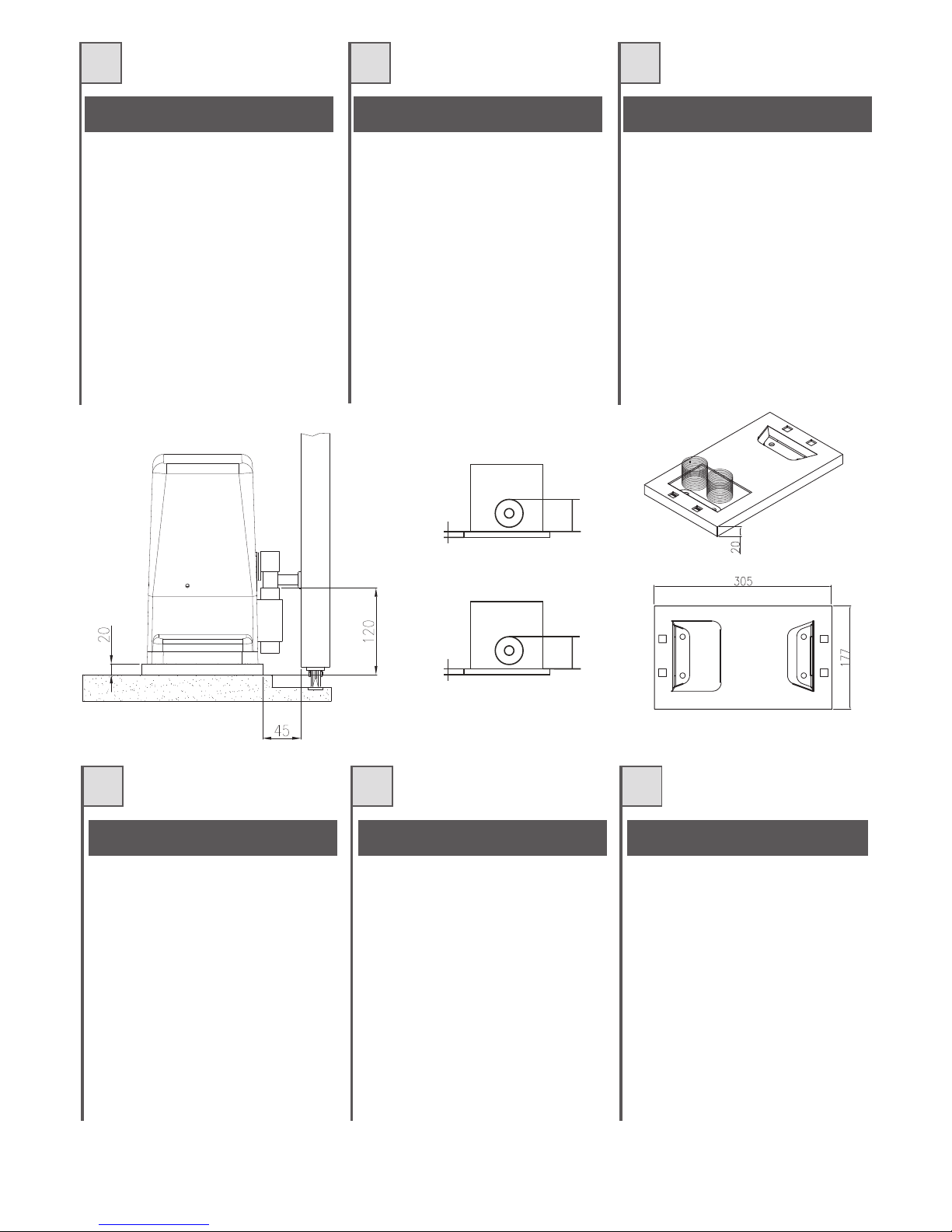
Prestare molta attenzione al verso di
montaggio. I fori per il passaggio delle
canalinedevonotrovarsiasinistra(fig.2).
Prestare molta attenzioneallequote indicate
nellafigura4.
D7GE7DG@FDAG7@F7@3@F5A?BF767E
6;?7@E;A@E67>3B>3CG7678A@63F;A@;9
%A97D63@E >7 FDAG>7E 93;@7E6;3? ??
jBAGD>7B3EE39767E5\4>7E
63>;?7@F3F;A@7F675A@@7J;A@7JF`D;7GD7
'AK7D63@E>74`FA@>7E93;@7E7F>3B>3CG767
8A@63F;A@3BD_E 7@3HA;D 5A@FDh>`3H75 G@
@;H73G>7E6;EF3@57E7F>:AD;LA@F3>;F`
+7EB75F7D>7E?7EGD7E7F>7E3@9>7E;@6;CG`E
63@E>3;93;@EF3>>3F;A@6DA;F77F63@E>3
;94;@EF3>>3F;A@93G5:7
>>7ED7BD`E7@F7@F>7?;@;?G?;@6;EB7@E34>7
BAGDG@355AGB>7?7@FB3D83;F7@FD7B;9@A@7F
5D`?3;>>_D7
%7E`H7@FG7>>7EB7F;F7E;?BD`5;E;A@E67
BAE;F;A@@7?7@F7@:3GF7GD7FBDA8A@67GD67>3
B>3CG7 678A@63F;A@B7GH7@FaFD75ADD;9`7E
63@EFAGE>7E53E7@39;EE3@FEG557EE;H7?7@F
EGD>7EKEF_?767D`9>39767>AB`D3F7GD
;J7D>7?AF7GDEGD>3B>3CG7G@;CG7?7@FCG3@6
>74`FA@E7D35A?B>_F7?7@FEA>;6;8;`7FE75
Faire trèsattention au sens de montage. Les
trous pour le passage des gaines doivent se
trouveràgauche(fig.2).
Faire très attention aux mesures indiquées
danslafigure4.
875Fl7 G@3 7J53H35;g@ 675;?7@F35;g@
F7@;7@6A7@5G7@F3>3E?76;63E67>3B>353
675;?7@F35;g@;9
A>ACG7>AE53@3>7E7@>37J53H35;g@
6;[? ?? jB3D3 :357D B3E3D >AE
534>7E673>;?7@F35;g@K675A@7J;g@
7JF7D@3
G4D35A@:AD?;9g@>AE53@3>7EK>3B>353
675;?7@F35;g@67EBG`E67:347D
5A@FDA>36A5A@ >33KG63 67G@ @;H7>>3E
5AF3EK>3:AD;LA@F3>;636+7EB7F7>3E
?76;63EK>AE[@9G>AECG7E7;@6;53@7@>3
;93;@EF3>35;g@67D75:3K7@>3;94
;@EF3>35;g@;LCG;7D63
+7BD7E7@F3@7>?c@;?A;@6;EB7@E34>7B3D3
A4F7@7DG@35AB>3?;7@FAB7D875FA7@FD7
B;eg@K5D7?3>>7D3
H7@FG3>7EB7CG7e3E;?BD75;E;A@7E67
7?B>3L3?;7@FA7@3>FGD3KBDA8G@6;63667>3
B>353675;?7@F35;g@E7BG767@5ADD79;D67
FA63E 8AD?3E355;A@3@6A EG57E;H3?7@F7 7>
E;EF7?367D79G>35;g@67>?AFADD76G5FAD
;<77> ?AFADEA4D7 >3B>353 Eg>A5G3@6A7>
:AD?;9g@E7:3K3EA>;6;8;536AKE7536A
B7D875F3?7@F7
Preste mucha atención al sentido del
montaje. Los orificios para el paso de los
canales tienen que encontrarse a la
izquierda(fig.2).
Preste mucha atención a las cotas
indicadasenlafigura4.
F
I
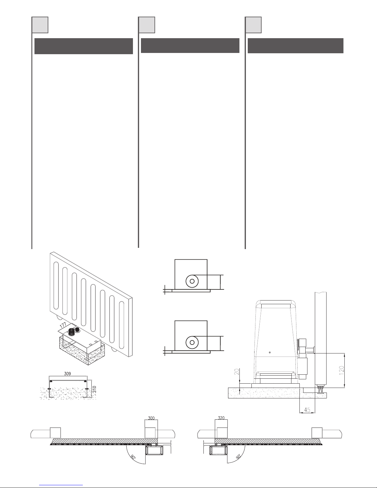
INSTALLAZIONE SU PIASTRA DI
FONDAZIONE (OPZIONALE)
INSTALLATION SUR PLAQUE DE
FONDATION (OPTION)
INSTALACIÓN SOBRE PLACA DE
CIMENTACIÓN (OPCIONAL)
;93443;94444
;944
;944
;944
45
45

7
GB D NL
;938AG@63F;A@:A>7F3=;@9;@FA
5A@E;67D3F;A@F:76;?7@E;A@EA8F:7
8AG@63F;A@B>3F7;9
)>357F:7 5:3@@7>6;3j?? 8ADF:7
BAI7DEGBB>K534>73@67JF7D@3>5A@@75F;A@E
;@F:7:A>7
,G4?7D97F:75:3@@7>E3@68AG@63F;A@B>3F7
;@FAF:75A@5D7F7BD7H;AGE>K:3H;@95:75=76
F:7:7;9:FE3@6>7H7> I;F:3EB;D;F >7H7>
A?B>KI;F:F:7?73EGD7?7@FE3@63@9>7E
;@6;53F76 ;@ ;93 D;9:F:3@6 ;@EF3>>3F;A@
3@6;@;94>78F:3@6 ;@EF3>>3F;A@F:3F
D7BD7E7@FF:7?;@;?G?@757EE3DK8AD3
B7D875F5AGB>;@9 47FI77@F:7 D35=3@6 F:7
B;@;A@
)AEE;4>7BAE;F;A@;@9;?B7D875F;A@E;@F:7:7;9:F
3@667BF:A8F:78AG@63F;A@ B>3F753@47
EG4E7CG7@F>K5ADD75F76F:DAG9:F:736<GEF?7@F
EKEF7?A8F:7973D?AFAD
;JF:7973D?AFADA@F:7B>3F7A@>KI:7@ F:7
5A@5D7F7:3EB7D875F>K:3D67@763@6;E
5A?B>7F7>K6DK
Take particular care of the assembly
direction. The holes for the passage of the
channel must be on the left (fig. 2).
Pay particular attention to the heights
indicated in Fig 4.
.@F7D7Dn5=E;5:F;9G@967D 4?7EEG@97@
67DG@63?7@FB>3FF7447;@G@63?7@F
3GE9D347@
"@67DGE9D34G@96;7$3@]>7GD5:???
jLG?GD5:8n:D7@67D/7DEAD9G@9E=347>
G@667D7JF7D@7@/7D4;@6G@9E=347>
G@F7D4D;@97@
;7&3Y7G@66;703397D75:F767D$3@]>7
G@667DG@63?7@FB>3FF7?;F7;@7D
03EE7DI3397=A@FDA>>;7D7@ 63@@6;7E7 ;?
7FA@H7DE7@=7@;7;@867@443
"@EF3>>3F;A@D75:FEG@64"@EF3>>3F;A@>;@=E
3@979747@7@&3Y74735:F7@M
,;7E;@66;78nD7;@77;@I3@68D7;7$ABB>G@9
LI;E5:7@+;FL7> G@623:@EF3@97G@476;@9F
@AFI7@6;97@&;@67EF?3Y7
$>7;@7.@97@3G;9=7;F7@47;?)AE;F;A@;7D7@67D
G@63?7@FB>3FF7 ;@ !i:7G@6 -;787 =i@@7@
3G5:EB]F7D?;F67?;@EF7>>EKEF7?67E
@FD;74E47D;5:F;9FI7D67@
7@@FD;747DEF3G867D)>3FF74787EF;97@I7@@
67D7FA@93@L87EFG@6FDA5=7@;EF
Den Montagesinn genau beachten. Die
Löcher zum Durchführen der Kanäle
müssen sich links befinden (Abb. 2).
Die in Abbildung 4 angegebenen Maße
genauestens einhalten.
&33=77@ 8G@67D;@9EBG@F7@:AG6633D4;<
D7=7@;@9?7F6738?7F;@97@H3@67
8G@67D;@9EB>33F384
D7@967 =347>9AAF<7E6;3???j
HAAD67=347>EHAADEFDAA?HAADL;7@;@97@
7JF7D@733@E>G;F;@9;@678G@67D;@9EBGF33@
%7967=347>9AAF<7E7@678G@67D;@9EB>33F
;@:7F 47FA@@363FG?7F 47:G>BH3@77@
I3F7DB3E 67I33D67@ 7@:7F 87;FA8 3>>7E
:AD;LA@F33>;E975A@FDA>77D6:74F'77?67
38?7F;@97@7@:A7=7@;@35:FLA3>E6;7AB
384 3 ;@EF3>>3F;7 D75:FE 7@AB 384 4
;@EF3>>3F;7>;@=E33@9797H7@L;<@L;<L;<@:7F
34EA>GF7?;@;?G?63F@AA6L3=7>;<=;EHAAD
77@B7D875F7 =ABB7>;@9FGEE7@DA@6E7> 7@
F3@6:7G97>
H7@FG7>7=>7;@7A@@3GI=7GD;9:767@;@
:AA9F7 7@6;7BF74;<:7FB>33FE7@H3@67
8G@67D;@9EB>33F=G@@7@75:F7DH7D:A>B7@
IAD67@6AAD >3F7D:7F 38EF7>EKEF77?H3@67
D76G5F;7?AFADF7974DG;=7@
7H7EF;967?AFADB3EAB67B>33FI3@@77D:7F
47FA@HA>=A?7@6DAA97@:3D6;E
Let heel goed op de richting van montage.
De boringen waar de k abelgootjes
doorheen moeten lopen, moeten zich links
bevinden (afb.2).
Let goed op de op afbeelding 4 aangegeven
waarden.
INSTALLATION ON THE FOUNDATION
PLATE (OPTIONAL)
NSTALLATION AUF FUNDAMENTPLATTE
(OPTIONAL)
INSTALLATIE OP FUNDERINGSPLAAT
(APART LEVERBAAR)
;944
;93443;94444
;944
;944
45
45
$)./''5$*) .0+$./-$)
*/5$*)
,7;>53@57>>A_BDAHH;EFA6;EA>;6A43E3?7@FA;@
57?7@FA;>?AFAD;6GFFAD7BGf7EE7D73@5AD3FA
6;D7FF3?7@F73>EGA>AGE3@6A>3B;3EFD36;
8;EE399;A8AD@;F33EE;7?73>?AFAD;6GFFAD75A@
CG3FFDADA4GEF;F3EE7>>;367EB3@E;A@78;9
H7@FG3>;B;55A>7;?BD75;E;A@;6;
BAE;L;A@3?7@FA ;@ 3>F7LL3 7 BDA8A@6;FZ67>>3
B;3EFD3 6;8;EE399;ABAEEA@A5A?G@CG77EE7D7
5ADD7FF7397@6AEG557EE;H3?7@F7EG>E;EF7?36;
D79A>3L;A@767>?AFAD;6GFFAD7
+E:FG6E:@B?G66GG:AM>BA:6??:DHBG:>A9>86G:
A:??6;><HE6
$)./''/$*).0-+',0 !*0-)$
,; >7 BADF3;> 7EF ?G@; 6G@7 EA>;67 43E77@
5;?7@F >AB`D3F7GDB7GF aFD78;J` 6;D75F7?7@F
EGD >7 EA>7@ GF;>;E3@F>3 B>3CG7678;J3F;A@
8AGD@;73H75>AB`D3F7GD3H75CG3FD79DAEE7E
5:7H;>>7EZ7JB3@E;A@8;9
%7E`H7@FG7>>7EB7F;F7E;?BD`5;E;A@E67
BAE;F;A@@7?7@F7@:3GF7GD7FBDA8A@67GD67>3
B>3CG7678;J3F;A@B7GH7@FaFD75ADD;9`7E63@E
FAGE>7E53E7@39;EE3@FEG557EE;H7?7@FEGD>7
EKEF_?767D`9>39767>AB`D3F7GD
!6>E:GEYF6GG:AG>BA6HK@:FHE:F>A9>DH:F
96AF?6;><HE:
$)./'$).*- +'
.*($)$./-
,; >353@57>36;EBA@7 67 G@343@536367
57?7@FAEg>;637>?AFADD76G5FADE7BG7678;<3D
6;D75F3?7@F77@7>EG7>AGF;>;L3@6A>3B>35367
8;<35;g@CG7E7EG?;@;EFD3<G@FA5A@7>
?AFADD76G5FAD5A@5G3FDAF35AE677JB3@E;g@
DA4GEFAE8;9
H7@FG3>7EB7CG7e3E;?BD75;E;A@7E67
7?B>3L3?;7@FA7@ 3>FGD3K BDA8G@6;63667>3
B>353678;<35;g@E7 BG767@5ADD79;D67 FA63E
8AD?3E355;A@3@6AEG57E;H3?7@F77> E;EF7?3
67D79G>35;g@67>?AFADD76G5FAD
+E:FG:@H8=66G:A8>A6?6F8BG6F>A9>8696F
:A?6;><HE6
"
)'
$)./''/$*)*)/# .0++'$
+'/
"8F:793F73>D736K:3E3EA>;65A@5D7F743E7
F:7@F:7973D?AFAD53@478;J766;D75F>KFAF:7
9DAG@6GE;@9F:78;J;@9B>3F7EGBB>;763>A@9
I;F:F:7973D?AFADI;F:8AGDEFGD6K7JB3@E;A@
4A>FE8;9
)AEE;4>7BAE;F;A@;@9;?B7D875F;A@E;@F:7
:7;9:F3@667BF:A8F:78AG@63F;A@B>3F753@47
EG4E7CG7@F>K5ADD75F76F:DAG9:F:7
36<GEF?7@FEKEF7?A8F:7973D?AFAD
+6L C6EG>8H?6E6GG:AG>BA GBG=: =:><=GF
>A9>86G:9>A!><
$)./''/$*)0!($/" '$ ! -/ -
+'//
3>>E63E-AD?;F7;@7?EA>;67@
27?7@F8G@63?7@FH7DE7:7@;EF=3@@67D
@FD;74?;F !;>8767D@=7DB>3FF7 ?;F97>;787DF
G@6H;7DDA4GEF7@,BD7;L6n47>@446;D7=F
?;F67?A67@H7D3@=7DFI7D67@
$>7;@7.@97@3G;9=7;F7@47;?)AE;F;A@;7D7@67D
@=7DB>3FF7 ;@ !i:7 G@6 -;787 =i@@7@ 3G5:
EB]F7D ?;F67?;@EF7>>EKEF7?67E @FD;74E
47D;5:F;9FI7D67@
>:>A 77>?9HA<6A<:<:7:A:A(6O:
<:A6H:FG:AF:>A=6?G:A
$)./''/$ *+( " ' 1 -
+'/
>E 67BAADFHAADL;7@;E H3@ 77@EF7H;97
9DA@6B>33FH3@57?7@F=3@67D76G5F;7?AFAD
D75:FEFD77=EAB674A67?H7D3@=7D6IAD67@
I33D4;<G6747H7EF;9;@9EB>33F974DG;=F
?7797>7H7D6?7F67D76G5F;7?AFAD?7FH;7D
EF7D=77JB3@E;7B>G997@384
H7@FG7>7=>7;@7A@@3GI=7GD;9:767@;@
:AA9F7 7@6;7BF74;<:7FB>33FE7@H3@67
8G@67D;@9EB>33F=G@@7@75:F7DH7D:A>B7@
IAD67@6AAD >3F7D:7F 38EF7>EKEF77?H3@67
D76G5F;7?AFADF7974DG;=7@
':G<B:9BC9:BC6;7::?9>A<66A<:<:I:A
J66E9:A
!
$
;944
;944
;944
9
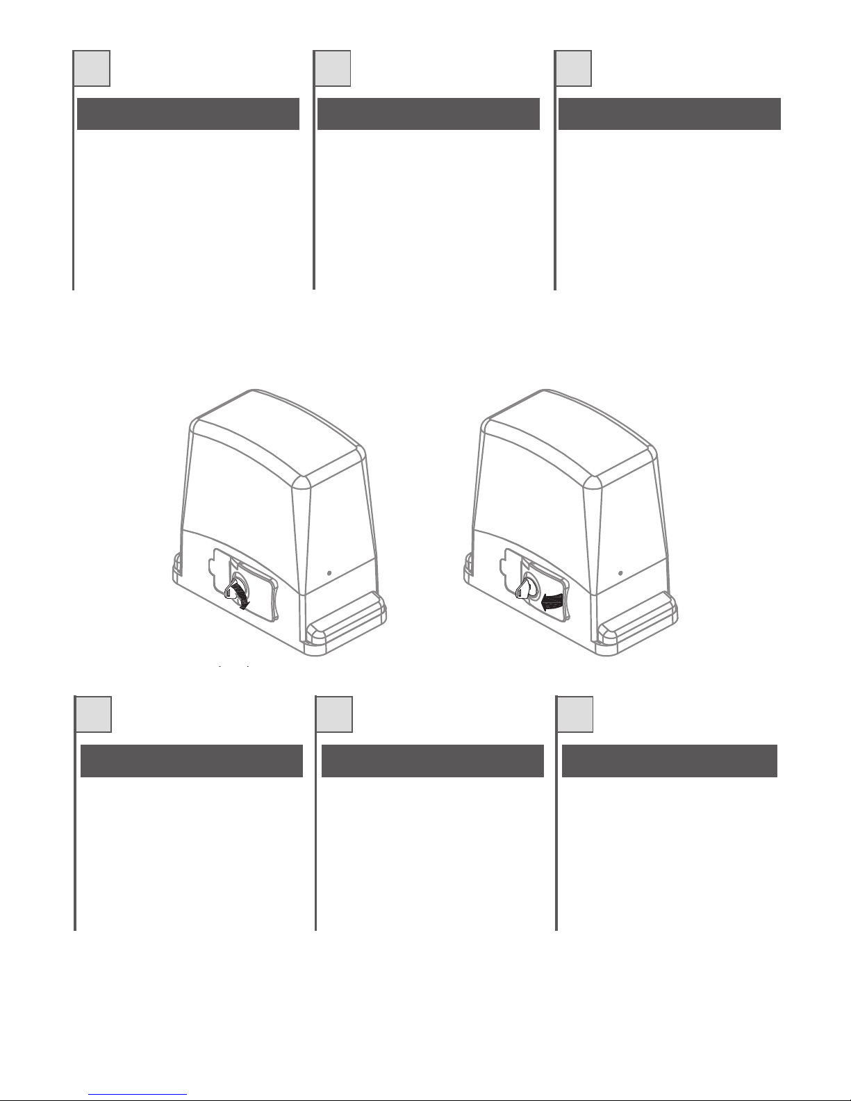
SBLOCCAGGIO DEL MOTORIDUTTORE
E
Per sbloccareilmotoriduttore inserire egirare la
chiave, tirare poi la leva dello sportellino come
indicatoinfig.6e7
DÉBLOCAGE DE L'OPÉRATEUR
Pour débrayer l'opérateur, introduire et tourner
la clé, tirer ensuite le levier de la porte comme
l'indiquelafig.6et7.
DESBLOQUEO DEL MOTORREDUCTOR
Para desbloquearelmotorreductor introduzcay
gire lallave, tire luegola palanca dela puerta tal
comoseindicaenlasfig.6y7.
GB
D NL
GEARMOTOR RELEASE
In order to release the gearmotor, insert and
turn thekey,then pulltheleverof thecoverflap
asindicatedinfigures6and7.
ENTRIEGELN DES ANTRIEBS
Zum Entriegeln des Antriebs, den Schlüssel
einstecken und drehen, dann den Hebel an der
Lukedrehen,wieindenAbb.6und7gezeigt.
ONTGRENDELING VAN DE
REDUCTIEMOTOR
Voor het ontgrendelen van de reductiemotor
dient u desleutelinhet slot testekenendieom
te draaien, vervolgens aan de hendel van het
luikje te trekken zoals dat op afb. 6 en 7 is
aangegeven.
F
I
Fig. 7 - Abb. 7
Fig. 6 - Abb. 6
10
E
Portareilcancelloincompletaapertura.
Sistemare ilmotoriduttoresulla piastra fissatain
precedenza mediante le apposite viti in
dotazione.
Regolare i grani di regolazione in altezza (vedi
particolare B di fig. 10) in modo che il
motoriduttore sialzidi circa4mmdalla piastradi
fissaggio.
Appoggiare un elemento di cremagliera al
pignone, e fissare lo stesso con viti e distanziali
alcancello.
Spostare manualmente il cancello portando il
pignone in corrispondenza dell'ultimo
distanziale.
Fissare l 'ele men to d i c r emaglier a
definitivamente.
Per un corretto posizionamento degli altri
elementi e garantire la loro rettilineità, è
necessario utilizzare un elemento di
cremagliera usandolo come appoggio e
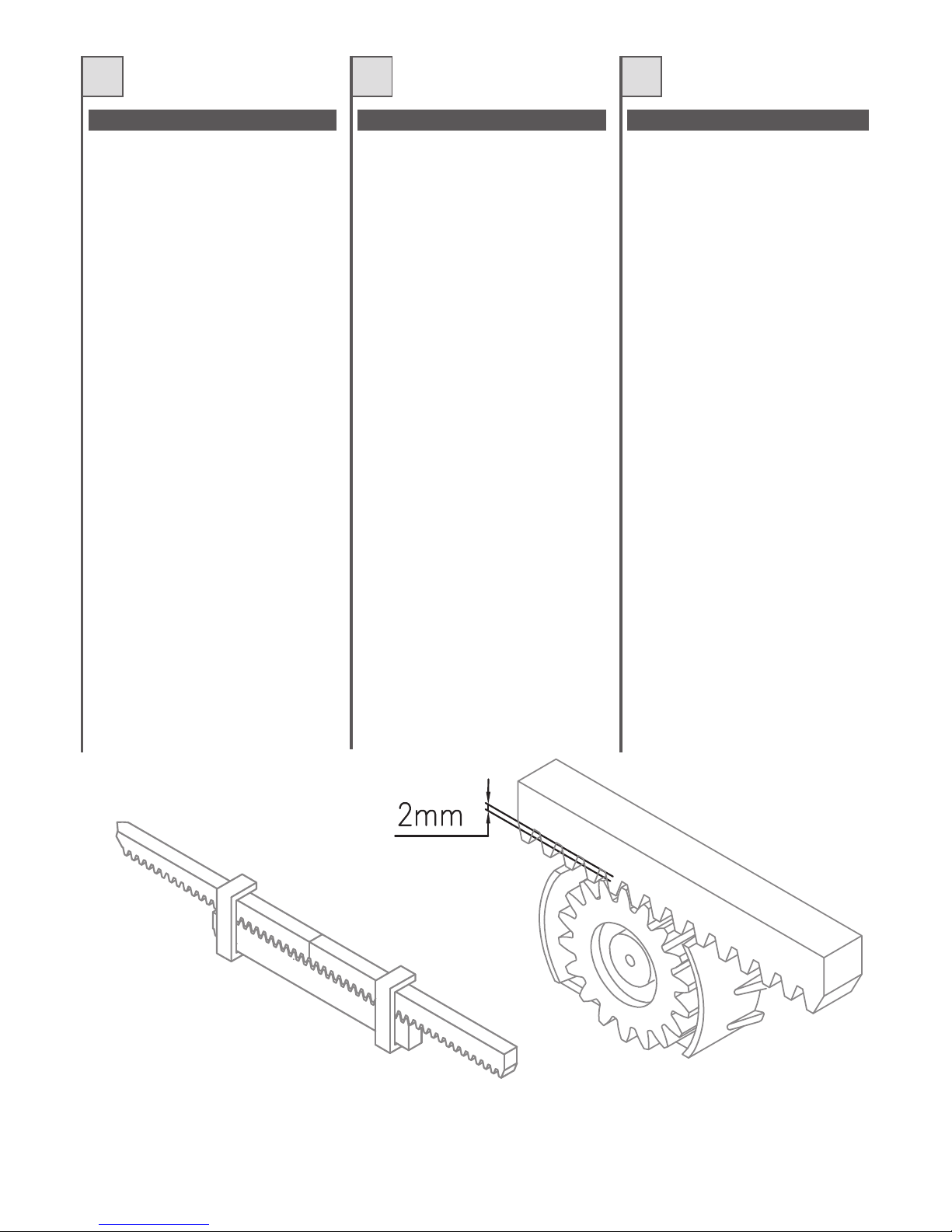
riferimento(Fig.8).
Si deve garantire un'aria fra cremagliera e
pignone di 2mm così danon far gravareil peso
del cancello sul pignone del motoriduttore (vedi
fig 9). Per far questo agire nei grani di
regolazionedelmotoriduttore(part.Bdifig.10).
Nel caso di cancelli nuovi verificare in tempi
successivi all'installazione il gioco fra
cremagliera e pignone, se necessario agire nei
grani di regolazione oppure sulle asole della
cremaglieraperregistrareigiochi
N.B.
Mettreleportailenouverturecomplète.
Placer l'opérateur sur la plaque précédemment
fixéeaveclesvisfournies.
Régler les goujons de réglage en hauteur (voir
détail B- fig.10) de manièreque l'opérateursoit
soulevé d'environ 4 mm par rapport à la plaque
defixation.
Appuyer un élément de crémaillère sur le
pignon, et lefixeravecdes vis et desentretoises
auportail.
Déplacer manuellement le portail en mettant le
pignonauniveaudeladernièreentretoise.
Fixerdéfinitivementl'élémentdecrémaillère.
Pour un positionnement correct des autres
éléments et pour qu'ils soient bien rectilignes, il
faututiliserun élément de crémaillère qui servira
d'appuietderepère(Fig.8).
Il faut garantir un espace de 2 mm entre la
crémaillère etle pignon demanière quele poids
du portail ne porte pas sur le pignon de
l'opérateur (voir fig. 9). Pour cela, agir sur les
goujons de réglagede l'opérateur (détailB - fig.
10).
Dans le cas de portails neufs, vérifier après
l'installation le jeu entre la crémaillère et le
pignon, si nécessaire agir sur les goujons de
réglage ou sur les fentes de la crémaillère pour
réglerlesjeux.
N.B.
Coloque la cancela en posición de apertura
completa.
Sitúe el motorreductor sobre la placa fijada
anteriormente mediante los tornillos
correspondientessuministrados.
Regulelosbulonesdecentrajederegulaciónen
altura(véasedetalleBdela fig.10)de formaque
elmotorreductorselevanteaproximadamente4
mmdela placadefijación.
Apoye un elemento de cremallera al piñón y
fíjelocon tornillosydistanciadoresala cancela.
Desplace manualmente la cancela situando el
piñón en el punto que coincide con el último
distanciador.
Fijeelelementodecremalleradefinitivamente.
Para conseguir un emplazamiento correcto de
losdemáselementosygarantizarsu rectitud,es
necesario utilizar un elemento de cremallera
usándolo como punto de apoyo y de referencia
(Fig.8).
Se tiene que garantizar un espacio entre la
cremalleray el piñónde2 mm paraevitarqueel
peso de la cancelano descanse sobre el piñón
del motorreductor (véase fig 9). Para ello
accione los bulones de centraje de regulación
delmotorreductor(part.Bdelafig.10).
Cuando se trata de cancelas nuevas,
compruebe sucesivamente a la instalación el
juego entre la cremallera y el piñón, en caso
necesario accione los bulones de centraje de
regulación o las ranuras de la cremallera para
reglarlos juegos.
N.B.
F
I
Fig. 8 - Abb. 8 Fig. 9 - Abb. 9
MONTAGGIO CREMAGLIERA MONTAGE CRÉMAILLÈRE MONTAJE DE LACREMALLERA
 Loading...