

Page 1

Tdev
System Installation Guide for
TMP5900
Issue 1A
Page 2

The information in this document is subject to change without notice. No part of this document may be reproduced or
transmitted in any form or by any means, electronic or mechanical, for any purpose, without the express written
permission of TelcoB ridges. TelcoBridges may have patents or pending patent applications, trademarks, copyrights, or
other intellectual property rights covering subject matter in this document. The furnishing of this document does not give
you license to these patents, trademarks, copyrights, or other intellectual property except as expressly provided in any
written license agreement from TelcoBridges.
The information provided in this document is intended as a guide only. For the latest detailed engineering specifications,
please contact Tel c o B ridges Customer Support. TelcoBridges is committed to continually improving product designs; as
a result, product specifications may be subject to change without notification.
© 2003-2011 TelcoBridges. All rights reserved.
TelcoBridges, Tmedia, TMP6400, TMP5900, TMG5800, TMG3200, TMP800, TMG800, TMS1600 Switch, Toolpack API, On a
Blade, System-Blade, TB-1+1 Solution, TB-16-E1/T1/J1, TB640-DS3, TB640-E1/T1/J1, TB640-OC3/STM-1, TB-8-E1/T1/J1, TBIVR Mezzanine, TB-Multi-Blade, TB-Multi-Blade Mezzanine, TB-N+1-15 Solution, TB-N+1-3 Solution, TB-StreamServer, TBVideo, TB-VoIP Mezzanine, TM-1000 Network Probe are trademarks of Tel c o B ridges Inc. All rights reserved 2009. All other
trademarks are property of their owners. This information is subject to change without notice.
Document Title: Tdev System Installation Guide for TMP5900
Document Number:,Issue 1A, 2010-11-28//12:27
HEAD OFFICE
91 rue de la Barre, Suite 01
Boucherville, Quebec
J4B 2X6, Canada
T +1 450 655 8993
F +1 450 655 9511
Page 3

About this Guide
This guide describes the installation and setup of the Tdev TMP5900 computer
telephony development platform and connections to voice, and IP networks.
Conventions
Terminology Description
Tdev Management Interface This is the interface used to configure and manage the TMP5900.
Contact Us
If you have comments about this guide or any other TelcoBridges technical
documentation, please send an E-mail to [email protected]
Preface
.
iii
Page 4

Tdev System Installation Guide for TMP5900
iv
Page 5

Table of Contents
Table of Contents
Chapter 1 Introduction ...................................................................................................................... 1
1.1 Installation Overview ...........................................................................................................2
1.2 Installation Prerequisites .....................................................................................................3
1.3 Preventing Electrostatic Discharge Damage....................................................................... 3
1.4 Recommended Reading .....................................................................................................4
Chapter 2 Equipment Connections ................................................................................................... 5
2.1 Package Contents............................................................................................................... 6
2.1.1 TMP5900 Package Contents ..............................................................................................6
2.2 Rack mounting the TMP5900.............................................................................................. 7
2.2.1 Prerequisites ....................................................................................................................... 7
2.2.2 Vertical Placement of TMP5900.......................................................................................... 7
2.2.3 Mounting the TMP5900.......................................................................................................8
2.3 Connecting to the Tdev Management Interface .................................................................. 9
2.3.1 Prerequisites ....................................................................................................................... 9
2.3.2 Interconnections.................................................................................................................. 9
2.4 Connecting to the VoIP Network ....................................................................................... 10
2.4.1 Prerequisites ..................................................................................................................... 10
2.4.2 Interconnections................................................................................................................ 11
2.5 Connecting to the PSTN ................................................................................................... 12
2.5.1 Prerequisites ..................................................................................................................... 12
2.5.2 RJ48 Type Interface (T1/E1/J1) ........................................................................................ 13
2.5.3 SCSI Interface (T1/E1/J1) .................................................................................................15
2.5.4 Dual BNC Interface (DS3)................................................................................................. 17
2.5.5 Optical Interface (OC3/STM-1).......................................................................................... 18
2.6 Powering Up...................................................................................................................... 19
2.6.1 Prerequisites ..................................................................................................................... 19
2.6.2 Connecting to AC Power................................................................................................... 19
2.6.3 Connecting to DC Power................................................................................................... 21
2.6.4 Verifying the LED Status Indications................................................................................. 22
2.7 Powering Down .................................................................................................................23
Chapter 3 Initial System Configuration ........................................................................................... 25
3.1 Configuring the TMP5900 ................................................................................................. 26
3.2 Setting the Time Zone....................................................................................................... 27
3.3 Configuring the Toolpack System Using the Web Portal ..................................................27
3.4 Changing the TMP5900 Host IP ......................................................................................28
3.5 Changing VoIP Interface Addresses ................................................................................. 28
3.6 Changing Passwords ........................................................................................................28
Chapter 4 System Upgrades........................................................................................................... 29
4.1 Installing a New License ................................................................................................... 29
v
Page 6

Tdev System Installation Guide for TMP5900
Chapter 5 Troubleshooting ............................................................................................................. 31
5.1 Connecting to the Serial Port of the TMP5900.................................................................. 32
5.2 Configuring the Terminal Emulator Application................................................................. 34
5.3 Reporting a Problem ......................................................................................................... 35
5.4 Setup Information.............................................................................................................. 35
5.5 Tbdebug Dump Files (Mandatory).....................................................................................35
5.6 Application Logs................................................................................................................ 35
5.7 Backdoor Tools ................................................................................................................. 36
5.7.1 tbx_cli_tools_remote ......................................................................................................... 36
5.7.2 Line/Trunk Status (Tbshowls)............................................................................................ 37
5.7.3 VoIP Traffic Capture.......................................................................................................... 37
5.7.4 Wireshark (formerly called Ethereal) ................................................................................. 38
5.7.5 Tbstreamlisten................................................................................................................... 38
5.7.6 Stream Server Audio Packets to Wave File ...................................................................... 38
5.7.7 tbsigtrace Signaling Traces............................................................................................... 38
5.8 Hard Disk Replacement .................................................................................................... 39
vi
Page 7

Chapter 1 Introduction
This chapter provides an introduction to the installation and setup of a Tdev system using the
TMP5900.
The following topics are covered:
• Installation overview
• Installation prerequisites
• Other recommended reading
Introduction
1
Page 8
Tdev System Installation Guide for TMP5900
Front
Rear
ETH VoIP TMS
12 1122
1
8
765432
916151413121110
1.1 Installation Overview
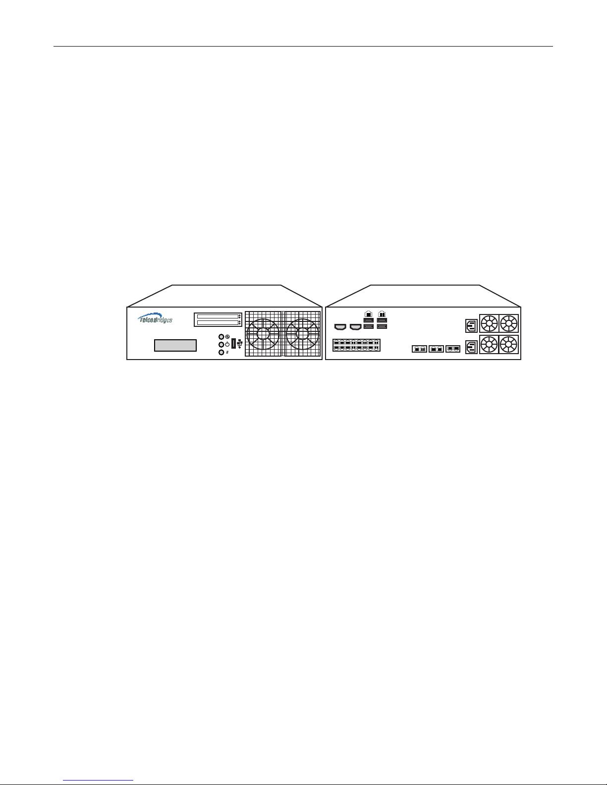
The installation and setup of a TMP5900 unit, as shown in figure 1.1 on page 2, is described by a series
of chapters dealing with installation tasks in the following order:
• Rack mounting the TMP5900
• Connecting to the Tdev Management Interfaces
• Connecting to the VoIP network
• Connecting to the PSTN
• Powering Up
• Initial System Configuration
• System Upgrades
• Troubleshooting
Figure 1.1 TMP5900, seen from front and rear.
2
Page 9

1.2 Installation Prerequisites
For the TMP5900 system installation to proceed without interruption, it is important that you verify that
you have on hand all of the necessary materials. Prior to beginning the installation, you should have
prepared for the following:
• Adequate space for the installation of your TMP5900. Consider that you will need to mount the
TMP5900 on a 19” customer-provided equipment rack.
• Adequate power supply and power connections. To guarantee an uninterrupted supply, the
TMP5900 must be powered by one (ideally two) independent dedicated power source(s). Only
TMP5900s with a DC-power option are supplied with power cords; therefore, you will need to plan
for your AC power cable requirements.
• To run your telecom applications on the TMP5900, you will need to have purchased an adequate
number of licenses for the features that you will use.
1.3 Preventing Electrostatic Discharge Damage
Electrostatic discharge (ESD) can damage equipment and impair electrical circuitry. It may occur if
electronic printed circuit cards are improperly handled and may cause complete or intermittent failure.
Introduction
Attention Always follow ESD prevention procedures when removing and replacing modules:
• Ensure that the TelcoBridges TMP5900 is electrically connected to earth ground.
• Wear an ESD-preventive wrist strap and ensure that it makes good contact with your
skin. Connect the wrist strap clip to an unpainted surface of the TMP5900 or the
grounded equipment rack in order to channel away all ESD voltage safely to ground.
To guard against ESD damage and shocks, the wrist strap and cord must be in proper
working condition.
• If no wrist strap is available, and you must work with the TMP5900, ground yourself by
touching a metal part of the chassis.
3
Page 10

Tdev System Installation Guide for TMP5900
1.4 Recommended Reading
This document assumes that you are well versed in the installation of the TelcoBridges TMP5900 and
have been trained to work with the equipment. If you have any technical questions, please contact
TelcoBridges technical support or send an E-mail to [email protected]
Other documents exploring various aspects of the Tdev system are available on the TelcoBridges TB
Wiki at: http://docs.telcobridges.com/mediawiki/index.php/Main_Page
.
4
Page 11

Chapter 2 Equipment Connections
This chapter provides the connection procedures for the TMP5900 as follows:
• Rack mounting the TMP5900
• Connecting to the Tdev management interfaces
• Connecting to a PSTN Network
• Connecting to an IP network
• Connecting Power
• Verifying LED Status
5
Page 12

Tdev System Installation Guide for TMP5900
2.1 Package Contents
You will have received one TMP5900. The TMP5900 is the telecom platform on which you will run your
telecom applications.
2.1.1 TMP5900 Package Contents
In the TMP5900 box, you will find:
• One TMP5900
• One set of mounting brackets with screws. These are used for the mounting of a TMP5900 on a 19”
rack.
• SCSI cables and patch panels. This is optional and only provided if the PSTN interface on your
TMP5900 features SCSI connectors.
• Three CAT5 Ethernet straight cables (male-male), three meters in length.
• One warranty sheet
• One packing slip
• One TMP5900 Quick Installation guide (a 1-page sheet that provides a pictorial view of equipment
setup).
• For DC units, two DC power cables are provided.
Not included with the TMP5900:
• No power cords are supplied for the AC units. Power cables are shipped with DC units only.
• A 19” equipment rack. You will use a standard 19” wide equipment rack to install the TMP5900.
6
Page 13

2.2 Rack mounting the TMP5900
The TMP5900 is mounted on a customer provided equipment rack using the mounting hardware
packaged in the box.
2.2.1 Prerequisites
To rack mount the TMP5900, you will need:
• One 19” customer provided equipment racks. The rack must be solidly anchored to the floor with
appropriate support at the top of the racks.
• Climate controlled room: 0 to +50 Celsius, 0 to 95% non-condensing humidity.
2.2.2 Vertical Placement of TMP5900
The TMP5900s are housed in 2U chassis, as tabulated in table 2.1 on page 7. It is important that you
provide for enough room on the equipment rack to allow for the installation of the TMP5900. Consider
the available space on your equipment rack and the height of the TMP5900. Due to the rear-exhaust
heat vents and the efficient heat dissipation design, there is no need to leave any physical vertical
space above or below the placement of the TMP5900 on the equipment rack.
Equipment Connections
Table 2.1 TMP5900 Physical Height
Tdev Model Number Vertical Height
TMP5900 2U
Patch Panels 1U
7
Page 14
Tdev System Installation Guide for TMP5900
Attach Bracket
to Tmedia Unit
Attach Tmedia
Unit to Equipment
Rack
2.2.3 Mounting the TMP5900
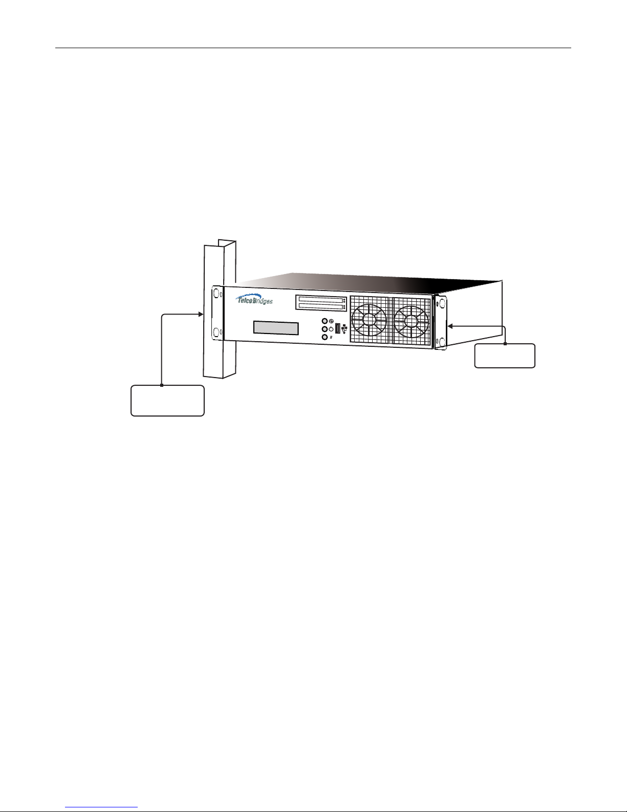
The TMP5900 is mounted on the 19” equipment rack using the angle brackets and screws provided in
the box. To mount the hardware, proceed as follows:
To mount the TMP5900 proceed as follows:
1. Using two metal screws, attach one angle bracket to the front, left-hand side of the TMP5900 when
viewed from the front, as shown in figure 2.1 on page 8. Repeat the same for the angle bracket on
the right-hand side.
2. Start mounting equipment at the top-most position of the rack, keeping in mind the space required
on the equipment rack as described in Section 2.2.2 “Vertical Placement of TMP5900” on page 7.
Figure 2.1 Mounting the TMP5900
8
Page 15
2.3 Connecting to the Tdev Management Interface
Management Interface
ETH VoIP TMS
12 1122
1
8
765432
916151413121110
Serial
232
RS
VGA
ETH0
ETH1
The Tdev Management Interface enables administrators to perform management tasks on the
TMP5900.
2.3.1 Prerequisites
To communicate with the Tdev Management Interface for a TMP5900, the following is needed:
• One CAT5 Ethernet cable with RJ45 male-male terminations.
2.3.2 Interconnections
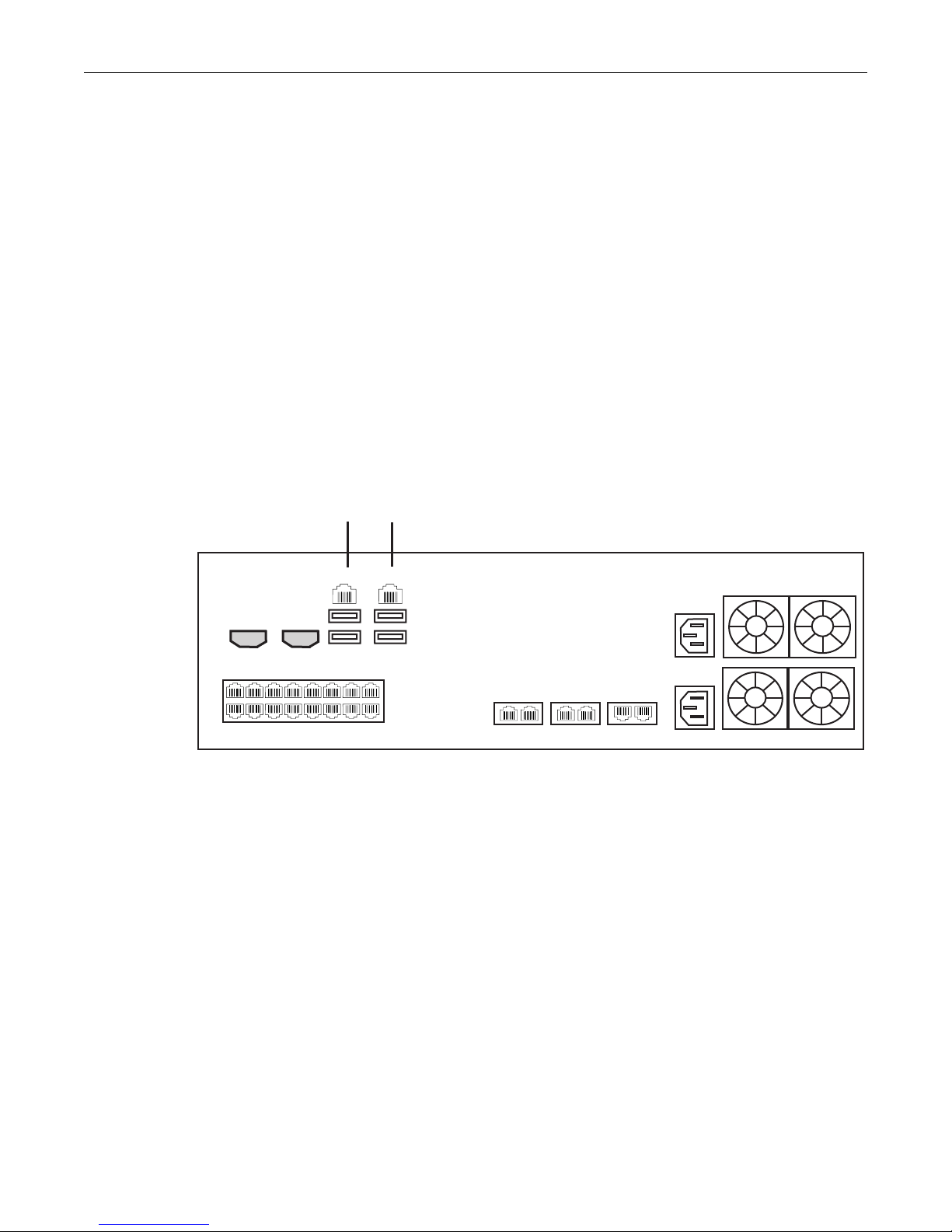
The TMP5900 provides a Tdev Management Interface, using one Gigabit Ethernet network link, as
shown in figure 2.2 on page 9.
To communicate with the Tdev Management Interface:
1. Connect the supplied CAT5 Ethernet cable to one of the upper ethernet ports located at the rear of
the TMP5900, and shown in figure 2.2 on page 9.
Equipment Connections
Figure 2.2 Tdev Management Interface
9
Page 16

Tdev System Installation Guide for TMP5900
2.4 Connecting to the VoIP Network
The TMP5900 features dual 100 Mbps/1000 Mbps ports for connection to different VoIP networks.
Should one of the IP networks fail, the TMP5900 will continue to handle VoIP traffic using the alternate
network.
Note: Certain configurations of the TMP5900 will exceed 100 Mbps, therefore
1000 Mbps is recommended.
2.4.1 Prerequisites
To connect the TMP5900 to the VoIP network, you will need:
• Gigabit Ethernet switch. A second one is required to support redundancy of the VoIP interface.
• One CAT5 Ethernet cable with RJ45 male-male terminations for each TMP5900.
• If your system has access to a second VoIP network, you can connect it to a second VoIP interface
of the TMP5900 with an RJ45 (male-male) CAT5 Ethernet cable.
10
Page 17
2.4.2 Interconnections
VoIP Network 1
VoIP Network 2
ETH VoIP TMS
12 112
2
1
8
765432
916151413121110
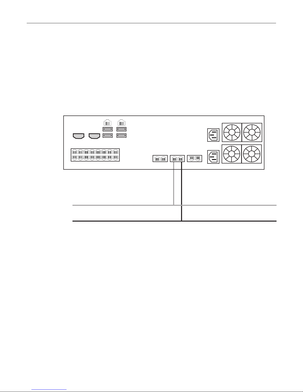
The TMP5900 is connected to the VoIP network by one or optionally two Ethernet GigE network links,
as shown in figure 2.3 on page 11.
To connect the TMP5900 to the VoIP network:
1. Connect a CAT5 Ethernet cable to VoIP1 at the rear of the TMP5900. Connect the other end of the
same CAT5 cable to the Gigabit Ethernet switch.
2. If your system employs a second Gigabit Ethernet switch for redundancy, connect a second CAT5
Ethernet cable to VoIP2 at the rear of the TMP5900. Connect the other end of the same CAT5
cable to the second Gigabit Ethernet switch.
Equipment Connections
Figure 2.3 Connecting to the VoIP Network
11
Page 18

Tdev System Installation Guide for TMP5900
2.5 Connecting to the PSTN
The TMP5900 features a variety of interfaces to the PSTN network. Each TMP5900 that makes
connection with the PSTN will feature a PSTN interface.
2.5.1 Prerequisites
To connect the TMP5900 to the PSTN network, you must comply with one of the following:
• Your TMP5900 features 16 modular 8-conductor RJ48 type jacks for connection to T1/E1/J1 lines.
You will need one cable for each (T1/E1/J1) interface on the TMP5900. If you are making your own
cables, refer to figure 2.5 on page 14 for crossover or straight cable wiring connections.
• Your TMP5900 features SCSI connectors for connection to T1/E1/J1 lines. You will require one
patch panel for each 32 line grouping of T1/E1/J1 line interfaces on the TMP5900.
• Your TMP5900 features BNC connectors for connection to DS3 lines. You will require two coaxial
cables for each DS3 interface.
• Your TMP5900 features electrical or optical STM 1connectors. You will require two fibre optic
cables for the STM 1 interface of the TMP5900.
12
Page 19
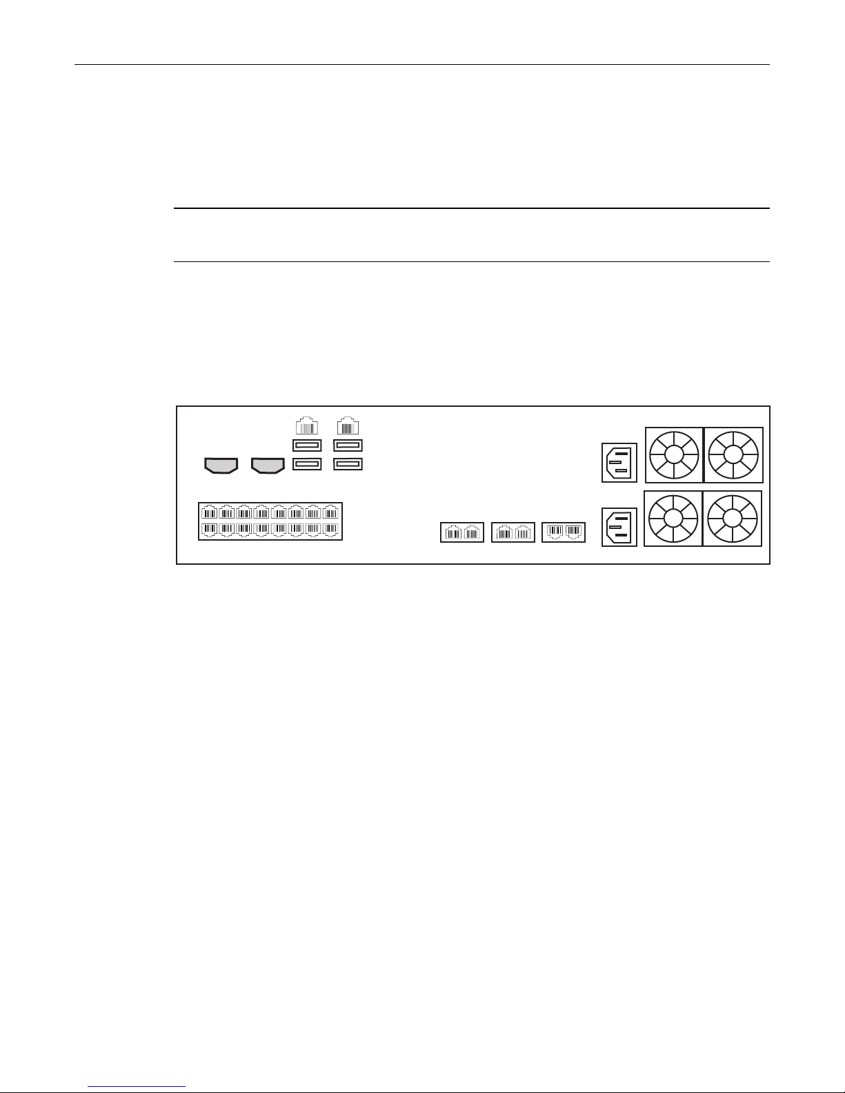
2.5.2 RJ48 Type Interface (T1/E1/J1)
ETH VoIP TMS
12 1122
1
8
765432
916151413121110
A TMP5900 with 16 RJ48 type ports enables the connection to T1/E1/J1 lines. The termination
impedance is set at 100 ohms for T1 lines and 120 ohms for E1 lines. It is possible to connect an
external balun in order to convert to 75 ohms. See figure 2.4 on page 13. If you are making your own
cables, refer to figure 2.5 on page 14 for crossover or straight cable wiring connections.
Note All ports may not be active. T1/E1/J1 ports are activated by software license; the number
of active ports depends on the licenses purchased.
To connect the TMP5900 (RJ48 type) to the PSTN:
1. Start with port 1 located at the top and left-most position. Connect one cable between this port and
the T1/E1/J1 line (figure 2.4 on page 13).
2. Repeat step 1, using the next available port.
Equipment Connections
Figure 2.4 16-Port Interface to the PSTN
13
Page 20
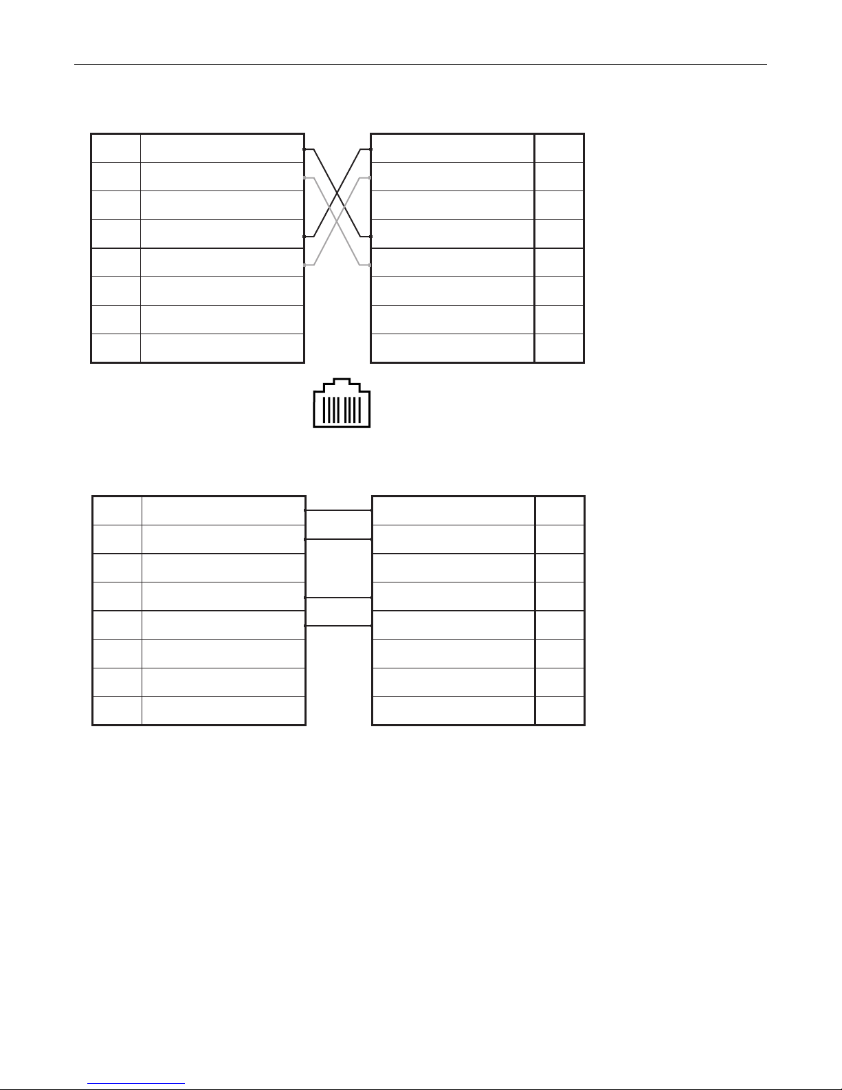
Tdev System Installation Guide for TMP5900
1
RX/Ring/-
2
RX/Tip/+
3
Not Connected
4
TX/Ring/-
5
TX/Tip/+
6
Not Connected
7
Not Connected
8
Not Connected
RJ 48 (T1/E1/J1) Wiring Schematic: Crossover Cable
1
8
RX/Ring/-
1
RX/Tip/+
2
Not Connected
3
TX/Ring/-
4
TX/Tip/+
5
Not Connected
6
Not Connected
7
Not Connected
8
1
RX/Ring/-
2
RX/Tip/+
3
Not Connected
4
TX/Ring/-
5
TX/Tip/+
6
Not Connected
7
Not Connected
8
Not Connected
RJ 48 (T1/E1/J1) Wiring Schematic: Straight Cable
RX/Ring/-
1
RX/Tip/+
2
Not Connected
3
TX/Ring/-
4
TX/Tip/+
5
Not Connected
6
Not Connected
7
Not Connected
8
Figure 2.5 RJ48 Wiring Schematic
14
Page 21

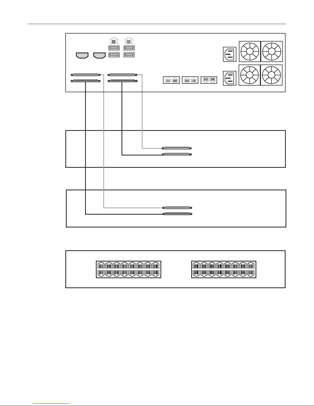
2.5.3 SCSI Interface (T1/E1/J1)
A TMP5900 with 4 SCSI connectors enables the connection to T1/E1/J1 lines. The termination
impedance is set at 120 ohms. It is possible to connect an external balun in order to convert to 75 ohms.
See figure 2.6 on page 16
Note All ports may not be active. T1/E1/J1 ports are activated by software license; the number
of active ports depends on the licenses purchased.
To connect the TMP5900 (SCSI) to the PSTN:
1. Start with the SCSI ports 1-16 located at the bottom right as shown in figure 2.6 on page 16.
Connect one SCSI cable between this port and SCSI patch panel number 1, ports 1-16. Connect
SCSI ports 17-32 to patch panel number 1, ports 17-32.
2. Repeat step 1, using lines 33-64 and a second patch panel. Connect lines 33-48 to patch panel 2,
port 1-16. Connect lines 49-64 to patch panel 2, ports 17-32.
Equipment Connections
15
Page 22
Tdev System Installation Guide for TMP5900
1
2
15
16
17
18
31
32
49-64
33-48
17-32
1-16
17-32
1-16
17-32
1-16
SCSI patch panel 1 rear
SCSI patch panel 2 rear
SCSI patch panel front
ETH VoIP TMS
12 1122
Figure 2.6 SCSI Interface to the PSTN
16
Page 23
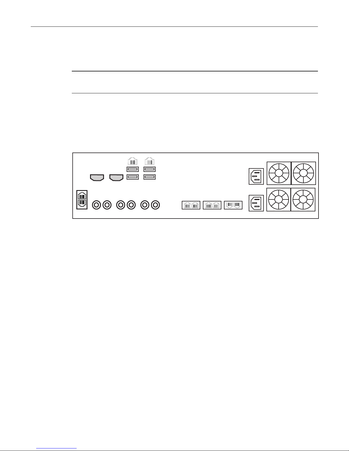
2.5.4 Dual BNC Interface (DS3)
RxTx
BIT1
BIT2
RxTxRxTx
32
1
ETH VoIP TMS
12 1122
A TMP5900 with 3 sets of BNC connectors enables the connection to DS3 lines. See figure 2.7 on
page 17
Note All ports may not be active. DS3 ports are activated by software license; the number of
active ports depends on the licenses purchased.
To connect the TMP5900 (DS3) to the PSTN:
1. Start with the Dual BNC port pair #1 (right-most) as shown in figure 2.7 on page 17. Connect one
pair of BNC cables between this port and the DS3 line.
2. Repeat step 1, using the next available pair of BNC PSTN interface ports.
Equipment Connections
Figure 2.7 DS3 Interface to the PSTN
17
Page 24
Tdev System Installation Guide for TMP5900
BIT1
BIT2
APS
MAIN
ETH VoIP TMS
12 1122
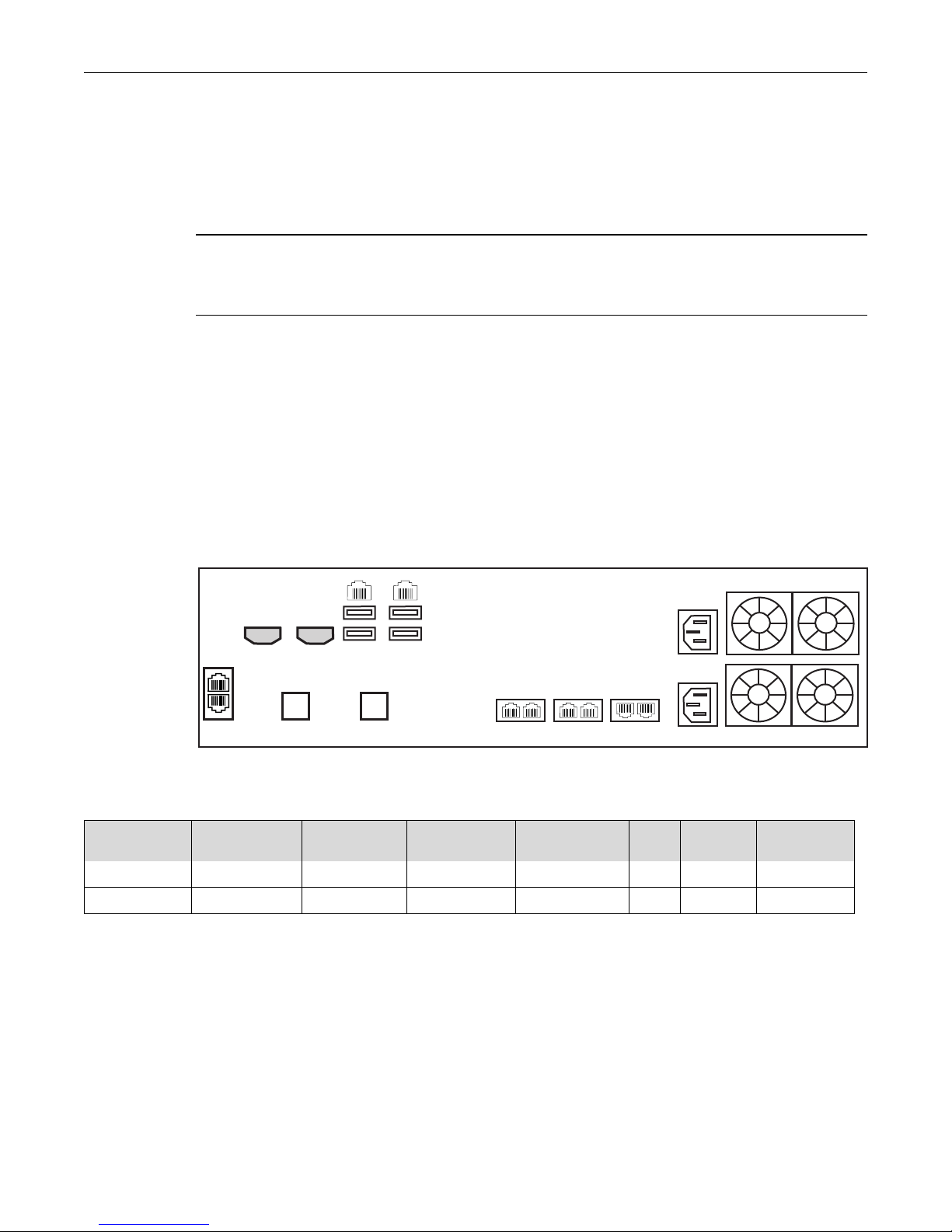
2.5.5 Optical Interface (OC3/STM-1)
A TMP5900, with one main and one backup OC3 or STM-1 port enables connection to OC3/STM-1
lines. See figure 2.8 on page 18. Refer to table 2.2 on page 18 for a listing of optical interfaces. The
default OC3/STM-1 connection is SMF, intermediate reach, (SFP-OC3-IR1) 1310 nm with LC type
connectors.
Note Please make certain that the correct model is selected at the time of ordering. If your
installation requires a different model from the one that has been provided, you must
replace it.
Automatic Protection Switching
The APS port is used for OC3/STM-1 redundancy. Switchover occurs automatically based on
configurable parameters. It is recommended that APS be used if the installation provides this feature.
To connect the TMP5900 (Optical Interface) to the PSTN:
1. Connect a fiber optic cable between the Main port and OC3/STM-1 line, as shown in figure 2.8 on
page 18.
2. Connect a fiber optic cable between the APS port and OC3/STM-1 line.
Figure 2.8 Optical Interface to the PSTN
Table 2.2 Optical Interfaces
Transceiver
Model
SFP-OC3-IR1 OC3/STM1 Hot Pluggable Single-mode Intermediate reach 15 1310 LC
SFP-STM1E STM1E (Electrical) Hot Pluggable 75 ohms Cooper Max 180m
a. Variable range
Description Spec Mode Ty pe Range
(Km.)
a
Wavelength
(NM)
NA DIN (mini-coax)
Connection
18
Page 25
2.6 Powering Up
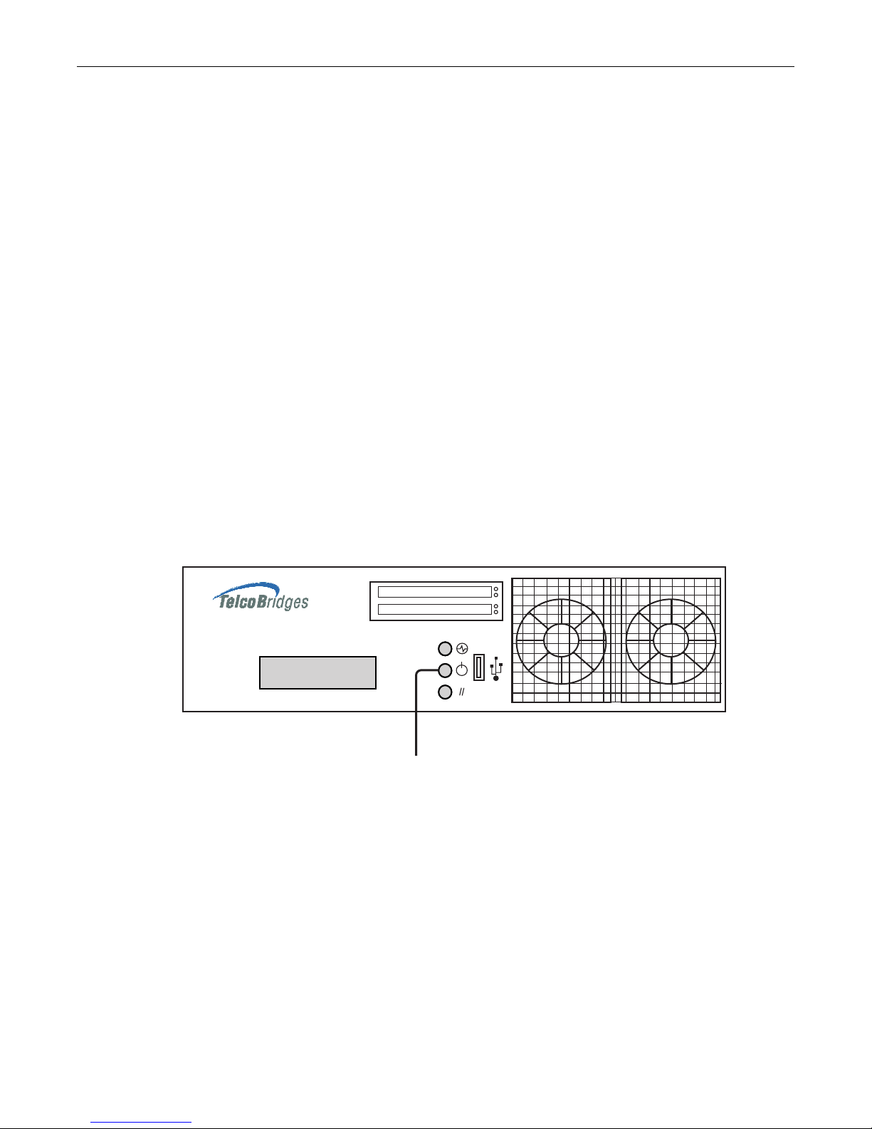
Power Button
The TMP5900 is furnished with two AC or DC power connections. Only once all other equipment
installation work has been completed should the TMP5900 be powered up.
2.6.1 Prerequisites
To power the TMP5900, you will need:
• A power source (ideally 2 independent power sources).
• Two power cables.
2.6.2 Connecting to AC Power
The TMP5900 is furnished with two AC power connectors.
To connect the TMP5900 to AC Power:
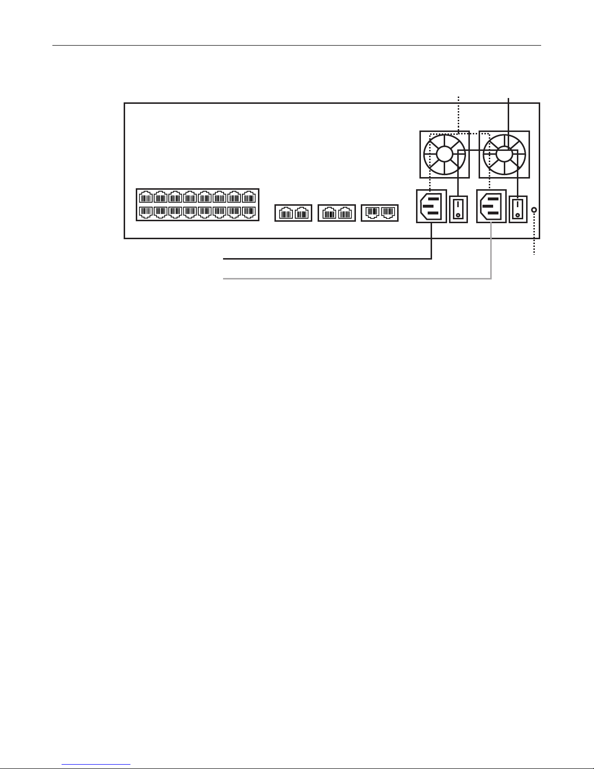
1. Connect the first AC power cable between the AC connector of the TMP5900 and an AC supply.
Connect the second AC power cable between the AC connector of the TMP5900 and a second AC
supply source. See figure 2.10 on page 20.
Equipment Connections
2. It is recommended that each power connector be connected to independent power sources. If the
second power supply is not connected to an AC power source, press the green button located at
the rear of the unit to disable the audible alarm. See figure 2.10 on page 20.
Figure 2.9 Power Button
19
Page 26
Tdev System Installation Guide for TMP5900
TMG3202
ETH VoIP TMS
1 2 11 22
To power
To power
Power
switch
Power
socket
Audible
alarm
button
1
9
8
16151413121110
765432
Figure 2.10 AC Power Connection
20
Page 27
2.6.3 Connecting to DC Power
ETH VoIP TMS
12 1122
1
8
765432
916151413121110
Serial
232
RS
VGA
ETH0
ETH1
+V
-V
Red
Black
NOTE:
DC power cable
supplied
Red
Black
+V
-V
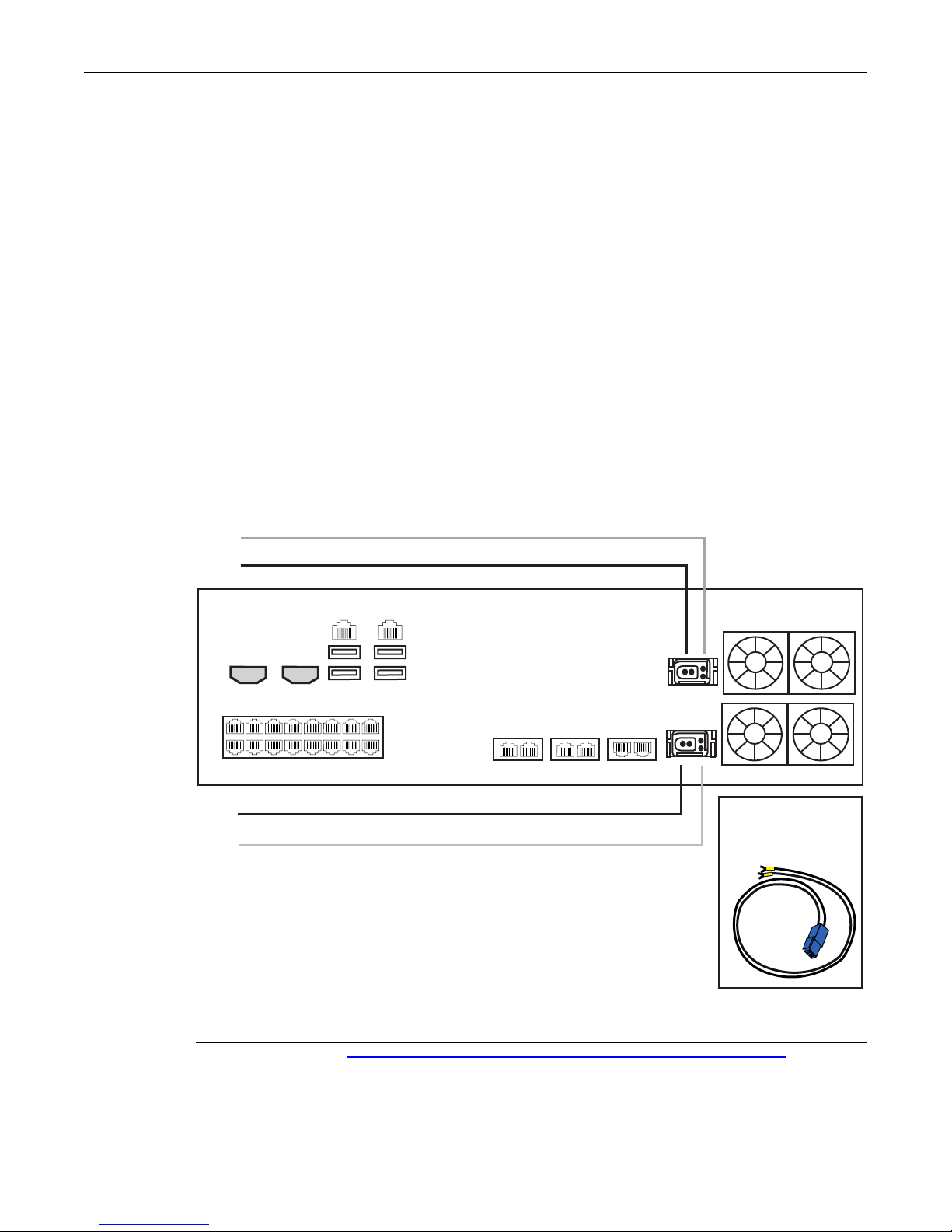
The TMP5900 DC models are furnished with two DC power connection ports. In addition, each DC
powered TMP5900 is supplied with a pair of DC power cables. The connection of DC power is
described for the TMP5900.
To connect the TMP5900 to DC power:
1. Connect the DC cable supplied with the TMP5900, as shown in figure 2.11 on page 21, to the DC
outlet at the rear of the TMP5900.
2. Connect one lead of the DC power cable to the positive terminal of the DC power source, as shown
in figure 2.11 on page 21.
3. Connect the other lead of the DC power cable to the negative side of the DC power source.
4. Repeat steps 1-3 for the second power DC power source.
5. It is recommended that each power connector of the TMP5900 be connected to independent power
sources. If the second power supply is not connected to a DC power source, press the green button
located at the rear of the unit to disable the audible alarm.
Equipment Connections
Figure 2.11 TMP5900 DC wiring diagram
Note Refer to http://docs.telcobridges.com/mediawiki/index.php/DC_cable_pinout for DC
cabling information.
21
Page 28
Tdev System Installation Guide for TMP5900
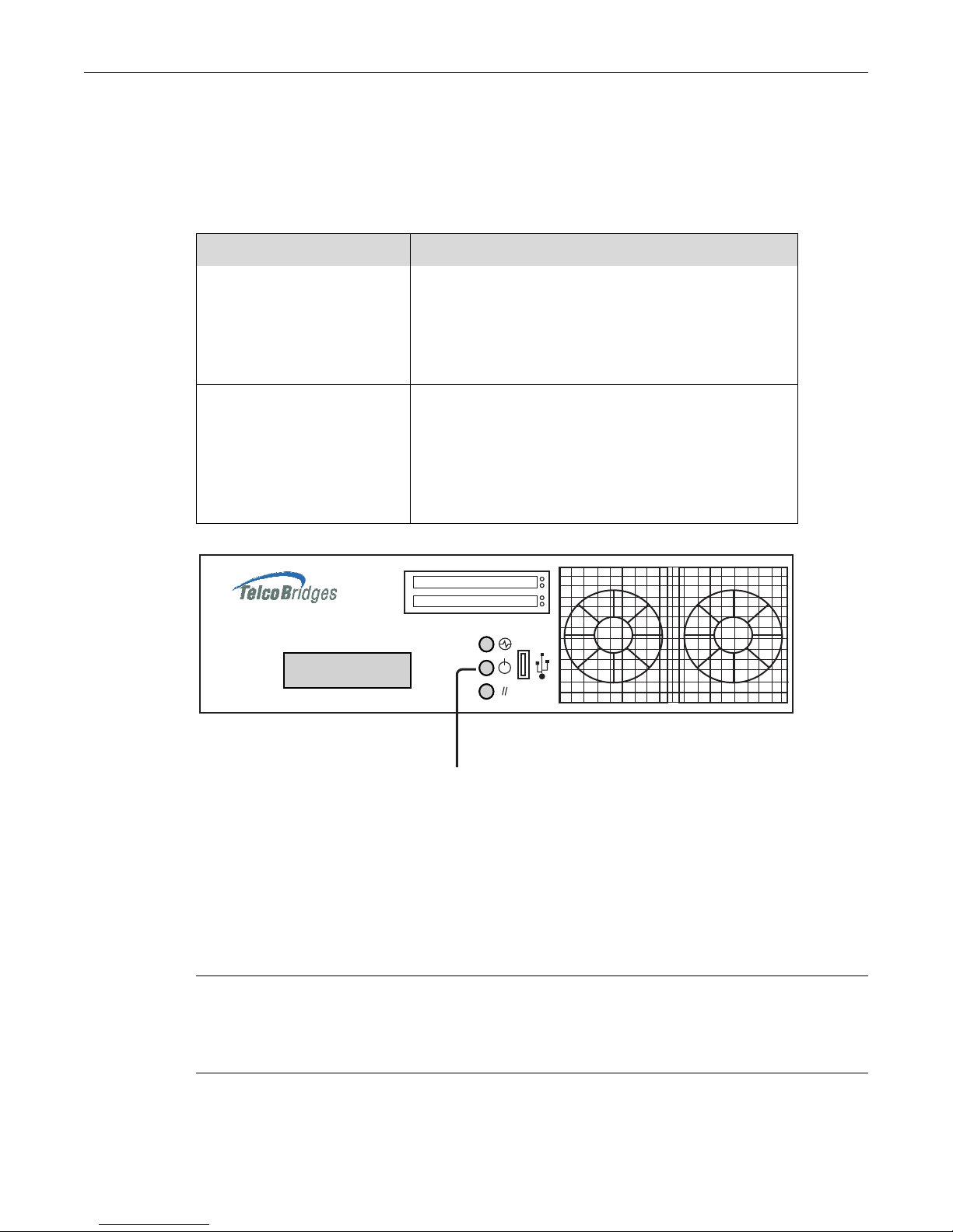
10 sec: Hardware Shutdown
1 sec: Software Shutdown
Display
Power Button
2.6.4 Verifying the LED Status Indications
When the TMP5900 has been powered, verify the front panel of the unit to determine that all indications
are normal. Once the TMP5900 has run successfully through its system boot procedures, the following
will be displayed in an alternating fashion as described in table 2.3 on page 22:
Table 2.3 TMP5900 Displays
Display Order Display
First Screen IP 0:
<ip address of eth0. E.g. 192.168.0.2>
IP 1:
<ip address of eth1 E.g. 192.168.0.3>
Second Screen <board type.. eg. TMP-STM1, TMS-16, TMP-DS3, TMP-
16, TMP-32, TMP-64>
<adapter name e.g. TB002821>
<serial number e.g. TB002821>
<release used e.g V2.2.0 RC1>
Figure 2.12 Front display and LEDs
The TMP5900 will perform a software shutdown, if the power button, see figure 2.12 on page 22, is
pressed for 1 second (highly recommended).
Note The TMP5900 will take about 1.5 minutes to do a software shutdown and there will be
indication that the TMP5900 is shutting down (The LED and display will not change).
The TMP5900 will perform a hardware shutdown, if the power button is pressed and held
for 10 seconds.
22
Page 29

2.7 Powering Down
DO NOT TURN OFF the power to the Tmedia
device using the power switch located at the
rear, unless the Linux host has been properly
shut down beforehand, using the reset button
display, or manually using the shutdown
command. Allow enough time for the Linux
host to shut down before turning the power to
the Tmedia unit off (e.g. 1 min). Be aware that
the shutdown procedure of the unit is logged
and traceable for support and warranty
purposes.
Powering down the TMP5900 requires that the Linux embedded host be shut down. In order to do this,
you must connect to the management interface using SSH, and enter:
shutdown -h now
Equipment Connections
Note As an alternate method to this procedure, refer to Section 2.6.4 “Verifying the LED Status
Indications” on page 22, to power down the TMP5900 with the reset button.
23
Page 30

Tdev System Installation Guide for TMP5900
24
Page 31

Chapter 3 Initial System Configuration
This chapter provides the initial procedures that are required in order for you to be
able to configure your TMP5900.
The following topics are covered:
• Configuring the TMP5900
• Setting the Time Zone
• Configuring the Toolpack System Using the Web Portal
• Changing TMP5900 Host IP Address
• Changing VoIP IP Interface Addresses
• Changing passwords
For information about Tblinux, a TelcoBridges™ Linux distribution running on the
embedded host of the TMP5900, refer to the Telcobridges TB Wiki at:
http://docs.telcobridges.com/mediawiki/index.php/Tblinux
25
Page 32

Tdev System Installation Guide for TMP5900
3.1 Configuring the TMP5900
The TMP5900 comes with the Toolpack and Media Gateway applications pre-installed. In order to
make changes to system configuration, you must connect the top-left port (Eth0) at the back of the
TMP5900 to a terminal.
The IP address of the TMP5900 is assigned automatically through DHCP, however, default
configurations can be changed manually.
The default hostname is the serial number of the embedded host. This can be found on the packing slip
along the “TM-CPU-HOST” item.
Connect directly to the TMP5900 or to the RS232 port. See Section 5.1 “Connecting to the Serial Port of
the TMP5900” on page 32. Default login information is root/root. Type the command “hostname” or
“ifconfig –a”:
[root@TB003540 ~]# hostname
TB003540
[root@TB003540 ~]# ifconfig -a
eth0 Link encap:Ethernet HWaddr 00:0C:38:00:0C:39
inet addr:10.0.0.236 Bcast:10.0.1.255 Mask:255.255.254.0
inet6 addr: fe80::20c:38ff:fe00:c39/64 Scope:Link
You can connect using the hostname or using the IP address assigned to eth0, using
port 12358:
http://HOSTNAME:12358
For example: http://TB003540:12358
26
Page 33

3.2 Setting the Time Zone
The time zone of the TMP5900 is configured on the Linux host using the tzselect command. The
following is provided as a sample of how to configure a time zone.
[root@TB005375 ]# tzselect
Please identify a location so that time zone rules can be set correctly.
Please select a continent
1) Africa
2) Americas
.
.
.
10) None - I want to specify the time zone using the Posix TZ format.
#? 2
Please select a country.
1) Anguilla
.
.
.
10) Canada
.
.
.
51) Virgin Islands (US)
#? 10
Please select one of the time zone regions.
1) Newfoundland Time, including SE Labrador
.
.
.
7) Eastern Time - Quebec - most locations
.
.
.
27) Pacific Time - north Yukon
#? 7
The following information has been given:
Canada
Eastern Time - Quebec - most locations
Therefore TZ= ‘America/Montreal’ will be used.
Local time is now: Wed Aug 19 08:49:01 EDT 2009.
Universal time is now: Wed Aug 19 08:49:01 UDT 2009.
Is the above information OK?
1) Yes
2) No
#? 1
You can make this change permanent for yourself by appending the line
TZ= ‘America/Montreal’; export TZ
to the file ‘.profile’ in your home directory; then log out and log in again.
Here is the TZ value again, this time on standard output so that you
can use the /usr/bin/tzselect command in the shell script
America/Montreal
[root@TB005373 ]#
Initial System Configuration
3.3 Configuring the Toolpack System Using the Web Portal
To change the default configuration of the Toolpack system using the Web Portal, follow the steps
described in the Web Portal System Configuration Tutorial Guide. This document can be obtained from
TelcoBridges TB Wiki at:
http://docs.telcobridges.com/mediawiki/index.php/Web_Portal_Tutorial_Guide_Versions
The default login information for the Web Portal application is:
• Username: root
• Password: root
27
Page 34

Tdev System Installation Guide for TMP5900
3.4 Changing the TMP5900 Host IP
A static IP address can be assigned to eth0, instead of using DHCP. To do this connect to the serial port
(see Section 2.3 “Connecting to the Tdev Management Interface” on page 9) and open the eth0
configuration file, using the procedure described in the Telcobridges TB Wiki at:
http://docs.telcobridges.com/mediawiki/index.php/TBLinux:How_to_change_the_ip_address
To return ETH0 or ETH1 to use DHCP, open the appropriate configuration file, using the same
procedure described in the Telcobridges TB Wiki at:
http://docs.telcobridges.com/mediawiki/index.php/TBLinux:How_to_change_the_ip_address
3.5 Changing VoIP Interface Addresses
The default address of the VoIP interfaces of the TMP5900 can be modified. To learn how this is done,
refer to the Toolpack Web Portal tutorial guide on the Telcobridges TB Wiki at:
http://docs.telcobridges.com/mediawiki/index.php/Web_Portal_Tutorial_Guide_Versions
3.6 Changing Passwords
Once logged in to the TMP5900, type “passwd”, in order to change the password being used. The
following information will be displayed:
[root@TB003540 ~]# passwd
Changing password for user root.
New UNIX password:
Retype new UNIX password:
passwd: all authentication tokens updated successfully.
28
Page 35

Chapter 4 System Upgrades
For information concerning system upgrades on a Telcobridges TMP5900, refer to the
Toolpack Install Guide for TMP5900. This document can be found on the Telcobridges
web site:
http://docs.telcobridges.com/mediawiki/index.php/Upgrading_Toolpack
4.1 Installing a New License
In order to install a new license on a Tdev system, follow the steps described on the
following internet page:
http://docs.telcobridges.com/mediawiki/index.php/Add/Change_Licenses
Note: A license upgrade may require that the TMP5900 be restarted.
'
29
Page 36

Tdev System Installation Guide for TMP5900
30
Page 37

Chapter 5 Troubleshooting
This chapter provides guidance in what actions to take when encountering system
problems prior to contacting TelcoBridges Customer Support.
The following topics are covered:
• Connecting to the serial port of the TMP5900
• Configuring the terminal emulator application
• Reporting a Problem
• Preparing your setup information
• TbDebug Debug Dump Files
• Application Logs
• Backdoor Tools
• tbsigtrace signaling traces
• Hard disk replacement
31
Page 38
Tdev System Installation Guide for TMP5900
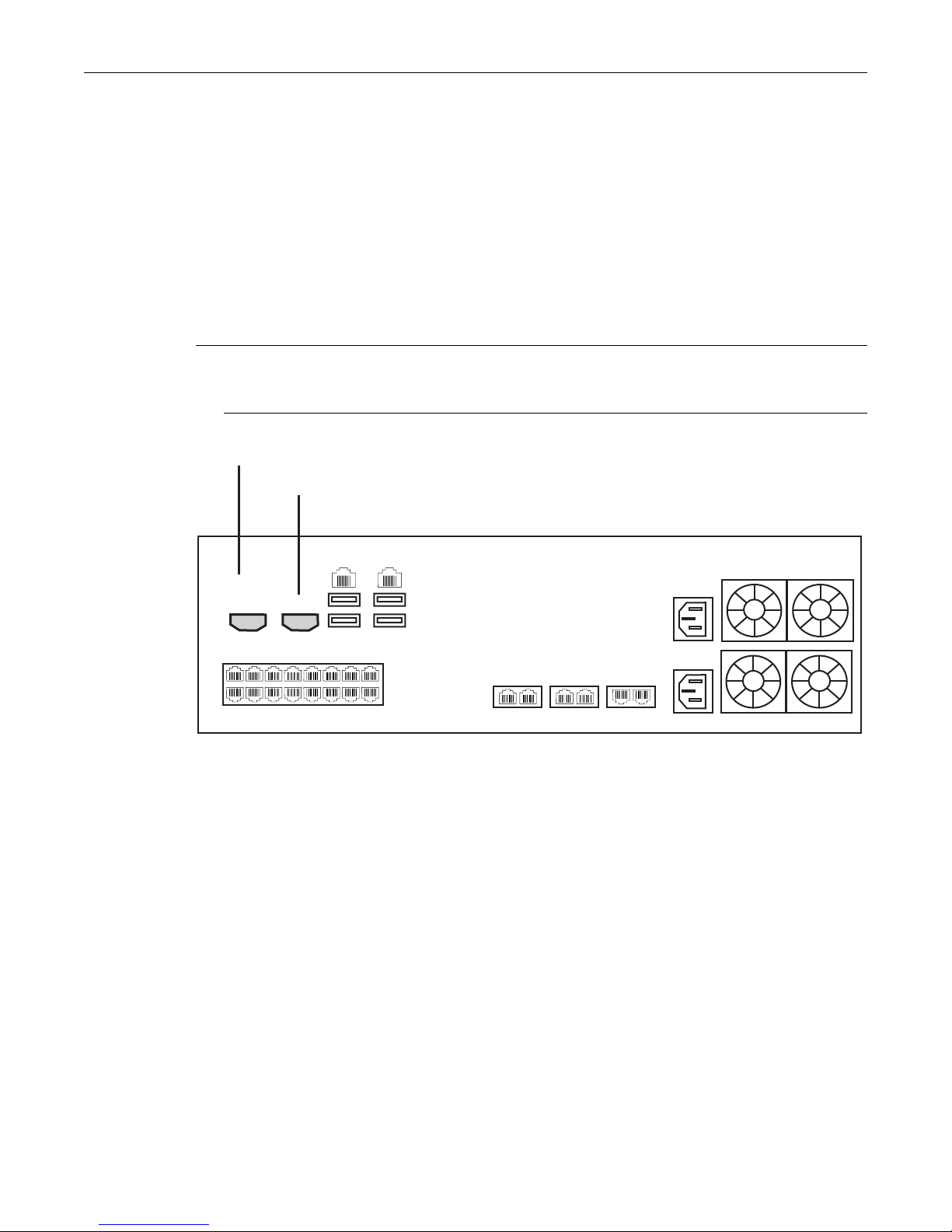
Serial port to the computer
VGA port to a monitor
ETH VoIP TMS
12 1122
1
8
765432
916151413121110
Serial
232
RS
VGA
ETH0
ETH1
5.1 Connecting to the Serial Port of the TMP5900
To view debug output data for a TMP5900, you must first physically connect your computer port to the
serial port of the TMP5900.
There are two ways to connect to the console of the TMP5900.
1. A monitor connected to the VGA connector (see Section 5.1 “VGA Port Pinout Description” on
page 33), at the rear of the unit. A keyboard and mouse can be connected to the USB ports at the
rear, or
2. RS-232 cable at the rear of the unit connected to another computer’s serial port
Note If you are connecting to the TMP5900 using the RS-232 port, you will need to set the serial
connection parameters. See Section 5.2 “Configuring the Terminal Emulator Application”
on page 34.
Figure 5.1 Computer to TMP5900 Serial Port Connection
32
Page 39

Table 5.1 VGA Port Pinout Description
Pin Signal Name Description
1 SPA_DCD DCD (carrier detect)
2 SPA_SIN_L RXD (receive data)
3 SPA_SOUT_N TXD (transmit data)
4 SPA_DTR DTR (data terminal ready)
5 GND Ground
6 SPA_DSR DSR (data set ready)
7 SPA_RTS RTS (request to send)
8 SPA_CTS CTS (clear to send)
9 SPA_RI RI (ring indicate)
10 NC no connection
Troubleshooting
33
Page 40

Tdev System Installation Guide for TMP5900
5.2 Configuring the Terminal Emulator Application
When connecting using the RS232 port of the TMP5900, you must first configure a terminal emulator or
console application to communicate with the TMP5900 in order to configure initial settings. Available
terminal emulation software includes:
• HyperTerminal
•Putty
•Minicom
To configure the terminal emulator application:
1. Set the baud rate (bits per second) to 115200
2. Set the data rate to 8 bits
3. Set the parity to None
4. Set the stop bits to 1
5. Set the flow control to None
34
Page 41

5.3 Reporting a Problem
TelcoBridges has developed extensive tools to gather information about a Tdev system to solve
problems quickly. Users MUST gather all related logs before reporting a problem to TelcoBridges
Support via Email or MSN. Various logging methods are described in the following sections.
Troubleshooting
Once information is gathered and sent to the TelcoBridges Support group ([email protected]
the Support group will assign a tracking number to the problem. All follow-up correspondence, whether
it be by E-mail, MSN, or phone call must refer to the tracking number which the problem has been
assigned.
5.4 Setup Information
The setup information must include:
• Physical connections. If necessary, describe it in a network diagram.
• Specifying that your product is a TMP5900.
• Telecommunication connectivity diagram (for example:. E1/T1/J1, DS3, STM-1/OC-3, VoIP
Ethernet switch, etc)
• Remote access to system (SSH, VPN, VNC, Remote desktop, etc.)
• For a signaling-related problem, specify which side is initiating the call
5.5 Tbdebug Dump Files (Mandatory)
The tbdebug copies information about Telcobridges libraries and TMP5900 into log files. This includes
software, the release running on the host, the firmware release running on the TMP5900, and other
TMP5900 information, such as: available features, configuration, and status information.
),
The tbdebug files must be sent when a problem is reported. If the problem is reproducible, the tbdebug
dump files are verified before and after the problem is reproduced. This will aid in identifying the
problem quickly.
For further information about Tbdebug, refer to Telcobridges TB Wiki at:
http://docs.telcobridges.com/mediawiki/index.php/Toolpack_Debug_Application:Tbdebug
5.6 Application Logs
All Toolpack applications will produce logs. The trace level can be set to vary the amount of logs that
are received from the system. Trace level 0 is the most verbose and 4 is the least. Important errors are
always logged.
/lib/tb/toolpack/setup/[SystemId]/[major version]/apps/gateway (Or customer's application)
tblogtrace
tboamapp
tbstreamserver
toolpack_engine
toolpack_sys_manager
/lib/tb/toolpack/
tbtoolpack_service
35
Page 42

Tdev System Installation Guide for TMP5900
/lib/tb/toolpack/pkg/[minor version]/web
Log
Database dump:
mysqldump -u [DbUserName] -password=[DbPassword] -opt toolpack_0 > toolpack_0.sql
For example: mysqldump -u tbdb -password=tbdbpw -opt toolpack_0 > toolpack_0.sql
Note This can be obtained from the web portal or by using the tbdebug command.
For further information on database backups, refer to
http://docs.telcobridges.com/mediawiki/index.php/Toolpack_v2.5:Database_Backup
5.7 Backdoor Tools
A number of backdoor tools are available as follows:
• tbx_cli_tools_remote
• tbshowls
• VoIP Traffic Capture
• Wireshark
• tbstreamlisten
• Stream server audio packets to wave file
• tbsigtrace
5.7.1 tbx_cli_tools_remote
The tbx_cli_tools_remote tool can be used to get the text-based GUI control of TB applications like
Toolpack_Engine, Toolpack_sys_manager, tbstreamserver, and others which are run in background.
For further information about tbx_cli_tools, refer to Telcobridges TB Wiki at:
http://docs.telcobridges.com/mediawiki/index.php/Toolpack_Application:tbx_cli_tools_remote
36
Page 43

5.7.2 Line/Trunk Status (Tbshowls)
tbshowls (/tb/bin/release/[OS version]/)
tbshowls can be used to show trunk alarm and performance counters. The tool will check the trunk
status periodically to show the most updated trunk status. Users can use the up/down/left/right arrow
keys to show the performance data on different trunks. Use a-s-d-x to scroll and view other lines
services.
Options 'G' and 'S' enable you to get and set the trunk interface parameters.
Option 'R' can be used to reset the performance counter value to zero.
It is also possible to allocate all line interfaces in different configurations. This is useful for DS3 and
OC3/STM-1 configurations, in order to help users understand the configuration.
Note Trunk status and alarms can be viewed from the Status menus of the Web Portal.
Note This tool is not supplied with the Toolpack installer but is available in the developer
package.
Troubleshooting
5.7.3 VoIP Traffic Capture
When troubleshooting VoIP related issues, a direct Ethernet connection can be established between
the host's Gigabit Ethernet interface and the VoIP1 interface on the TMP5900. Wireshark is connected
on the Gigabit Ethernet interface on the host server.
To capture VoIP Traffic, do the following:
1. Connect VoIP1 interface to Ethernet port of a server
2. Connect to the telecom platform
2a. Using telnet, for example: [root@TB005375 ]# telnet 172.31.1.1
or
2b. Using minicom, for example: [root@TB005375 ]# minicom
3. Type this command:
mv88eMonitor 0x4 0x4 3 (Copies everything from VoIP0 to VoIP1) *
4. Start pcap capture on the server Ethernet port (either wireshark or tcpdump)
5. To stop the tracing:
mv88eMonitor 0 0 3
37
Page 44

Tdev System Installation Guide for TMP5900
5.7.4 Wireshark (formerly called Ethereal)
Wireshark is useful for capturing both VoIP traffic as well as Streamserver packets (play/record
function).
This program is available at this site: www.wireshark.org
5.7.5 Tbstreamlisten
tb\apps\tbstreamlisten\release\[OS version]
This allows the recording of the raw data from a TDM stream. Please ask customer support for
instructions regarding this function.
Note This tool is not supplied with the Toolpack installer but is available in the developer
package.
5.7.6 Stream Server Audio Packets to Wave File
It is possible to capture all audio packets transmitted to and from the Stream Server and to convert
them into wave files for analysis. You can use Wireshark or tcpdump on the server running the
tbstreamserver application.
The conversion tool, streamserver_pkt_to_wav can be found at the following location:
/tb/bin/release/[OS version].
Note This tool is not supplied with the Toolpack installer but is available in the developer
package.
5.7.7 tbsigtrace Signaling Traces
The tbsigtrace program is a tool used to capture SS7, ISDN, and SIP signaling.
Note This application can be started with Toolpack. For further information, refer to the
TelcoBridges TB Wiki at:
http://docs.telcobridges.com/mediawiki/index.php/Toolpack_Debug_Application:Tbsigtrace
38
Page 45
5.8 Hard Disk Replacement
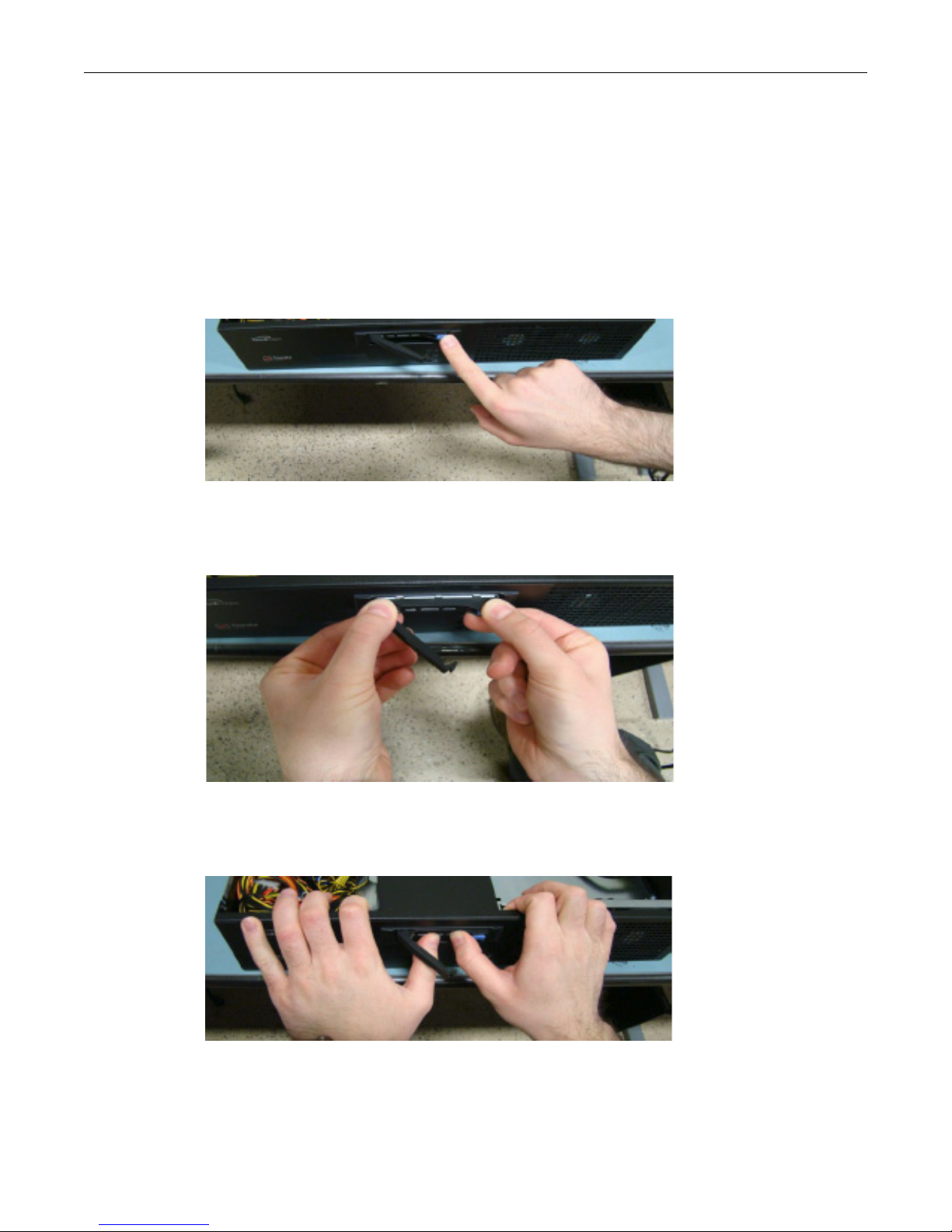
The TMP5900 has two hard drives set up as Raid 1. If a hard drive fails, the system will continue to
operate without problem.
It is also possible to replace a failed disk without any interruption to service. To do this, proceed as
follows:
1. Press the blue release button to retract the drive.
Troubleshooting
2. Pull the drive out of the drive slot. Avoid using the small plastic arm.
3. Insert the new drive into the drive slot. Use your thumbs to firmly seat the drive.
39
Page 46
Tdev System Installation Guide for TMP5900
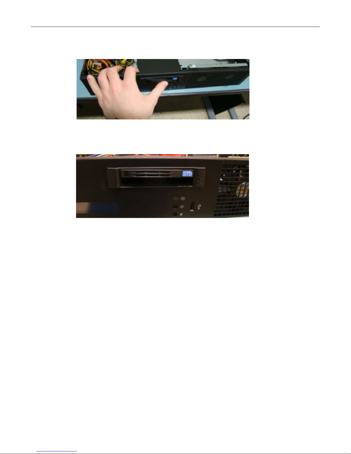
4. Clip the plastic arm into place, to firmly secure the drive.
5. Contact TelcoBridges support to enable Raid on the newly installed hard drive.
40
 Loading...