

Page 1
SGP30 - USER MANUAL
Space Guard Proximity Series
Photoelectric light curtain
Website: www.telcosensors.com
Warning
V
1.1 Part Number: 0666220765
E-Mail: [email protected]
This product is not a safety system and must not be used as such.
It is not designed for personnel safety app lications, and must not be used
as a stand alone personnel safety system.
April 2015 edition
Made in Denmark
Telco A/S reserves the right to make c hanges without prior notice
tel
!
EN
Product Data
Electrical Data
Supply voltage
12 —
30 V dc
Max. voltage ripple
15 % (within supply range)
Max. current consumption
120 mA (RMS)
Max. output load
200 mA
Output Reverse polarity protected
Yes
Output short circuit protected
Yes
Output inductive load protection
Yes
Environmental Data
Light immunity @5º incidence
> 100.000 lux
Temperature, operation
-30 to + 60 ºC
Sealing class
IP 67
Marking
Available Models
Model
Beam spacing Sensing Range
SGP 30-xxx-0xx-A1-M-xx-xx 46 mm 1,3 m
Connection
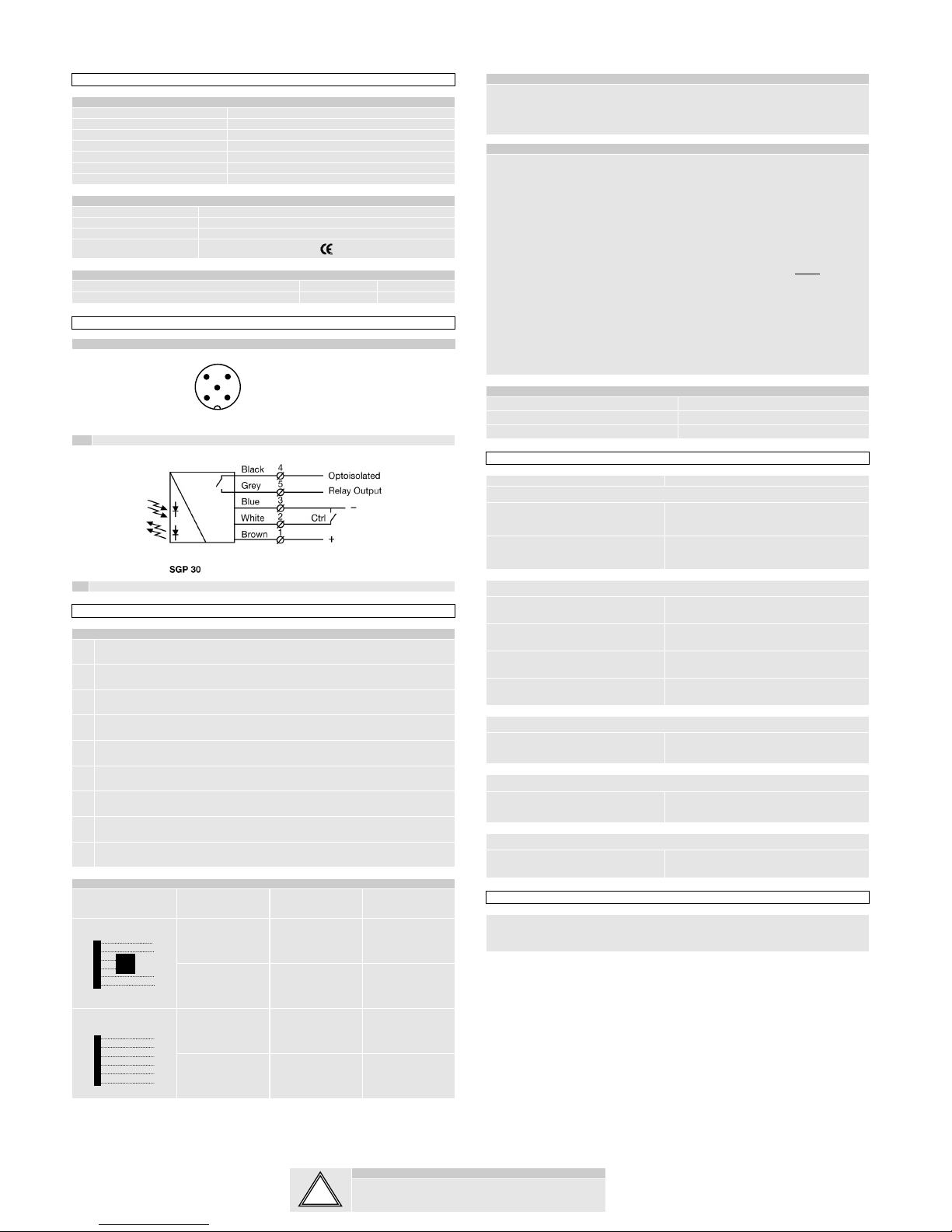
Wiring Diagrams
SGP30 5 pin M12 male connector
Wiring diagram
Installation & Adjustments
Adjust ment
1 Mount the SGP30 unit.
2
Wire the sensor according to the wiring diagram.
Make sure the output load does not exceed 200 mA.
3 Check for correct wiring before turning power on.
4 When the power on indicator (green LED) is on the system is operating.
5
Use the control wire to blank any IR channels which unintended has proximity effect on
the output or decrease the sensing range.
6 Adjust the sensing range with potentiometer mounted in the top plastic plug of the rail.
7
If necessary use the control wire again to blank any IR channels which unintended has
proximity effect on the output.
8
After power on make sure that the output indicator (yellow LED) change state when an
object is placed in front of the rails and within the sensing range.
9 The light curtain is only intended for static applications.
Output Logic
Detection Output mode Output status
Output indicator
(yellow LED)
Object present
Dark operated
(N.C.)
Open Off
Light operated
(N.O.)
Closed On
Object absent
Dark operated
(N.C.)
Closed On
Light operated
(N.O.)
Open Off
A
djusting sensing range
With the potentiometer mounted in the top plastic plug of the rail the sensing range can be
adjusted from 0 m to 1,3 m. The sensing range is at its maximum when the potentiometer is
fully clock wise. Notice that when increasing the sensing range it can be necessary to blank IR
beams because nearby objects unintentionally can be detected.
Blanking function mode, Ctrl input
This function is used to blank out beams that otherwise constantly would detect close lying
surfaces or objects, for instance construction elements as metallic frames, support pillars or
beams. When an IR beam is blanked it cannot change the state of the output.
The blanking mode is activated by powering up the SGP30 with pin 2 (white Ctrl wire)
connected to ground (-). In this mode every IR beam that detects something, even temporarily,
will be blanked and stored in non-volatile memory. Pin 2 should at least be connected to
ground as long as the output indicates that one or more IR beams detects objects and the red
LED is not lit. If there are movement in close laying objects this can take some seconds.
When the blanking procedure is finish pin 2 must be removed from ground (-) before power to
the SGP30 is removed, otherwise no IR beams will be blanked. During normal operation pin 2
must be left floating. The blanking is now permanent, also after power down, until new
blanking has been made.
The green LED will flash three times after power-up if any IR beams are blanked.
If blanking shall be deactivated there are two options:
1. Repeat blanking process, but without nearby objects or surfaces that can cause
blanking.
2. Repeat blanking process, with the potentiometer turned to 0.
Indicators
Red LED Status indicator
Yellow LED Output indicator
Green LED Power on indicator
Troubleshooting
Probable Reason
Corrective Action
1. Symptom: Status indicator (Red LED) is constant on.
SGP30 is in blanking mode and blanking
is completed.
Remove pin 2 from ground (-).
Internal failure. Return SGP30 unit to factory.
2. Symptom: Output indicator (Yellow LED) on is flashing.
Severe electrical interference. Separate supply cable from high voltage cables.
Severe ambient light. Shield, reposition or twist SGP30.
Cross talk from another light curtain or
photo sensor
Shield or reposition SGP30 or other photo
sensor.
Cross talk from a nearby HF strip light Shield, reposition or twist SGP30.
3. Symptom: With NO output red LED, yellow LED is constant on and output is closed.
One or more IR beams have proximity
effect.
If necessary perform a blanking process or
remove object(s) or lower amplification by
turning potentiometer anti clock wise.
4. Symptom: With NC output red LED and yellow LED is constant off and output is open.
One or more IR beams have proximity
effect.
If necessary perform a blanking process or
remove object(s) or lower amplification by
turning potentiometer anti clock wise.
5. Symptom: Red LED is off and output is stocked.
SGP30 is out of sensing range. Adjust the sensing range with potentiometer.
Disposal
Disposal should be done using the most up-to-date recycling technology according to local
rules and laws.
1 2
3
4
5
1: Brown
2: White
3: Blue
4: Black
5: Black or Yellow/
g
reen
Page 2
SGP30 - USER MANUAL
Space Guard Proximity Series
Photoelectric light curtain
Website: www.telcosensors.com
Warning
V
1.1 Part Number: 0666220765
E-Mail: [email protected]
This product is not a safety system and must not be used as such.
It is not designed for personnel safety app lications, and must not be used
as a stand alone personnel safety system.
April 2015 edition
Made in Denmark
Telco A/S reserves the right to make c hanges without prior notice
tel
!
EN
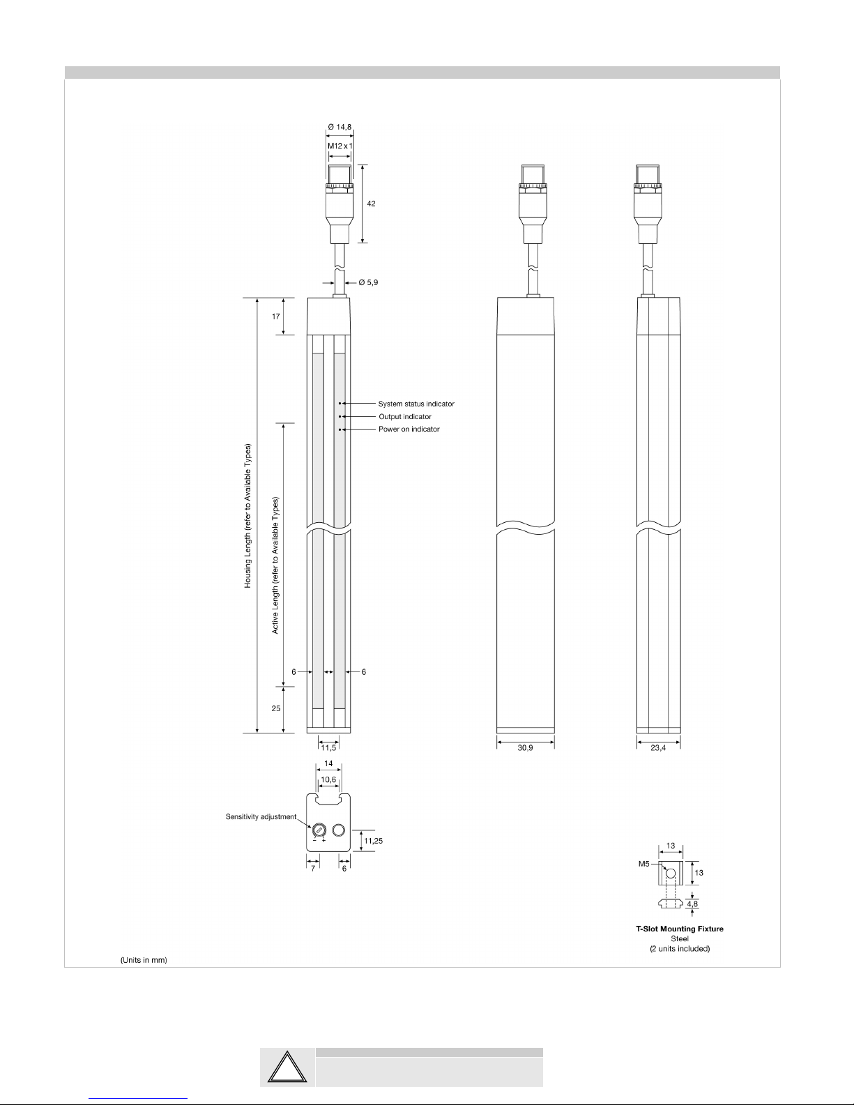
Dimensions and Descriptions
 Loading...