

Page 1

Version 1.1.27 / 04/2016 Copyright KURTH ELECTRONIC GmbH
All rights reserved, including translations.
All reprints and electronic copies, including excerpts, require prior written approval of
Kurth Electronic.
All of the brand names and trademarks cited herein are the property of their
registered owners.
Operating
Manual
®
KE2500
Telco Multimeter
Page 2
KURTH ELECTRONIC www.kurthelectronic.de [email protected]
Operating Manual
KE2500 Telco Multimeter
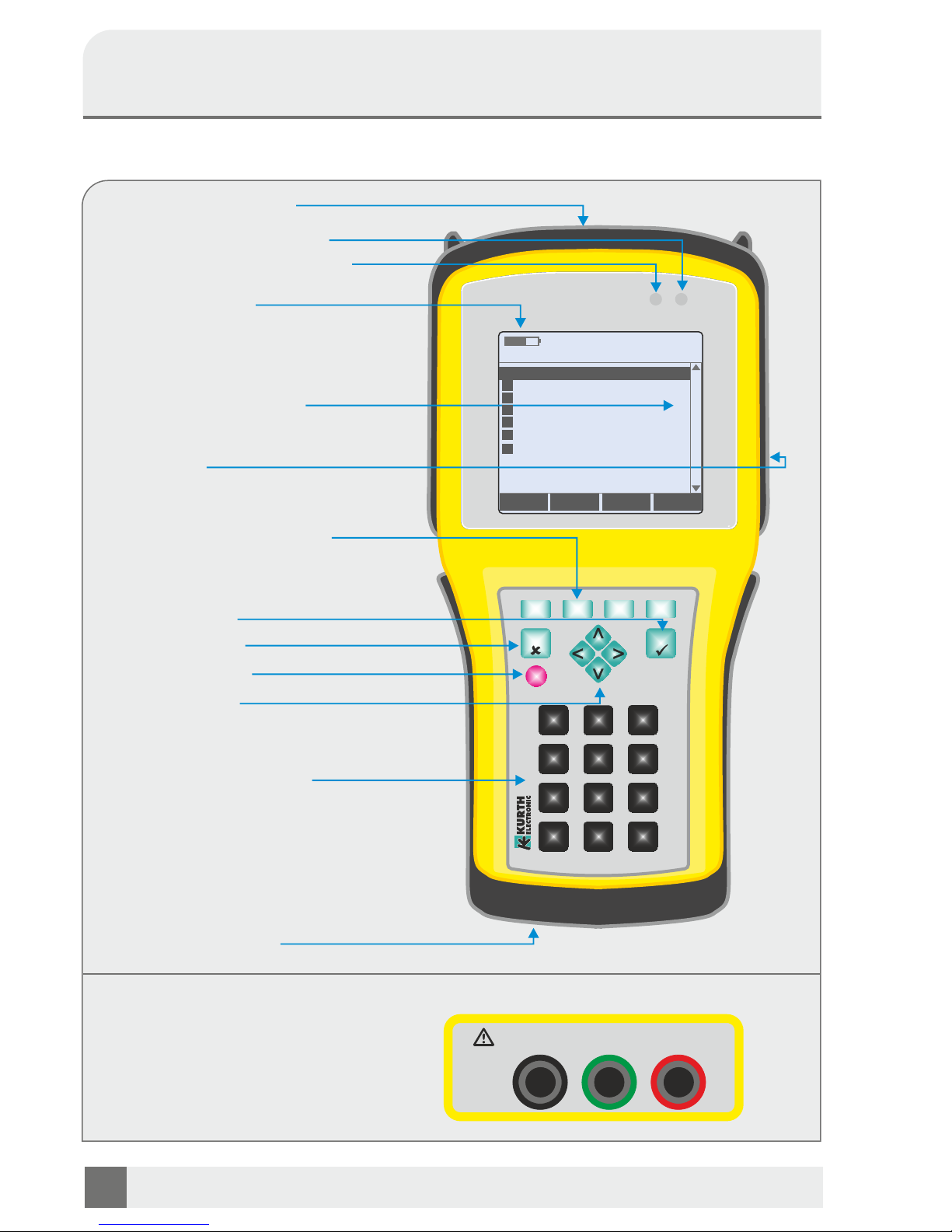
Keyboard / display / connections
2
BATT
CHRG
KE2500
Telco Multimeter
F1
F2
F4
F3
0
*
#
1
2
3
ABC
DEF
4
5 6
GHI
JKL
MNO
7
8 9
PQRS
TUV
WXYZ
ESC
SEL
ON
OFF
ABE
-
+
Test leads
n Wire A red
n Wire B green
n Ground E black
Graphic LCD display
USB port
Connection sockets
Input jacks (top of unit)
Select button
Power supply jack
Battery display
Menu buttons
UP - DOWN / LEFT - RIGHT
Escape button
ON/OFF button
Function buttons F1 - F4
Alphanumeric keypad
LED charging indicator
LED indicator USB access
Main Menu
Line Multimeter
LoopAnalysis
Remote Switch Type <KE90x>
Remote Switch Functions
Cable Parameters
Date / Time
1
2
3
4
5
Allow USB Access6
Setup7
Page 3

Operating Manual
Telco Multimeter KE2500
Contents
Introduction . . . . . . . . . . . . . . . . . . . . . . . . . . . . . . . . . . . . . . . . . . . . . . . . . . . . . . . . . . . 4
Symbols used. . . . . . . . . . . . . . . . . . . . . . . . . . . . . . . . . . . . . . . . . . . . . . . . . . . . . . . . . . 4
Safety instructions and warnings . . . . . . . . . . . . . . . . . . . . . . . . . . . . . . . . . . . . . . . . . . . 4
Operation . . . . . . . . . . . . . . . . . . . . . . . . . . . . . . . . . . . . . . . . . . . . . . . . . . . . . . . . . . . . 6
KE2500 – Functions . . . . . . . . . . . . . . . . . . . . . . . . . . . . . . . . . . . . . . . . . . . . . . . . . . . . 6
Battery calibration . . . . . . . . . . . . . . . . . . . . . . . . . . . . . . . . . . . . . . . . . . . . . . . . . . . . . . 6
Connectors and test leads . . . . . . . . . . . . . . . . . . . . . . . . . . . . . . . . . . . . . . . . . . . . . . . 7
General operating . . . . . . . . . . . . . . . . . . . . . . . . . . . . . . . . . . . . . . . . . . . . . . . . . . . . . . 8
1. Line Multimeter . . . . . . . . . . . . . . . . . . . . . . . . . . . . . . . . . . . . . . . 9
1.1 Voltage . . . . . . . . . . . . . . . . . . . . . . . . . . . . . . . . . . . . . . . . . . . . . . . . . . . . . . . . . . 9
1.2 Resistance line . . . . . . . . . . . . . . . . . . . . . . . . . . . . . . . . . . . . . . . . . . . . . . . . . . . 10
1.3 Resistance line balanced . . . . . . . . . . . . . . . . . . . . . . . . . . . . . . . . . . . . . . . . . . . 10
1.4 Insulation . . . . . . . . . . . . . . . . . . . . . . . . . . . . . . . . . . . . . . . . . . . . . . . . . . . . . . . 11
1.5 Capacitance . . . . . . . . . . . . . . . . . . . . . . . . . . . . . . . . . . . . . . . . . . . . . . . . . . . . . 11
1.6 Capacitive balanced . . . . . . . . . . . . . . . . . . . . . . . . . . . . . . . . . . . . . . . . . . . . . . . 12
1.7 Ground return resistance . . . . . . . . . . . . . . . . . . . . . . . . . . . . . . . . . . . . . . . . . . . 12
1.8 LCL 1 MHz . . . . . . . . . . . . . . . . . . . . . . . . . . . . . . . . . . . . . . . . . . . . . . . . . . . . . . 12
1.9 PPA and Signature detection . . . . . . . . . . . . . . . . . . . . . . . . . . . . . . . . . . . . . . . . 13
1.10 Current . . . . . . . . . . . . . . . . . . . . . . . . . . . . . . . . . . . . . . . . . . . . . . . . . . . . . . . . . 13
1.11 Insulation (quick) . . . . . . . . . . . . . . . . . . . . . . . . . . . . . . . . . . . . . . . . . . . . . . . . . . 13
2. Loop Analysis . . . . . . . . . . . . . . . . . . . . . . . . . . . . . . . . . . . . . . . . 14
2.1 Loop Analysis w/o CO . . . . . . . . . . . . . . . . . . . . . . . . . . . . . . . . . . . . . . . . . . . . . 14
2.2 Loop Analysis with CO . . . . . . . . . . . . . . . . . . . . . . . . . . . . . . . . . . . . . . . . . . . . . 15
2.3 Loop Analysis (auto) . . . . . . . . . . . . . . . . . . . . . . . . . . . . . . . . . . . . . . . . . . . . . . . 16
2.4 Schleifenanalyse QA8 07/2014. . . . . . . . . . . . . . . . . . . . . . . . . . . . . . . . . . . . . . . 16
3. Remote Switch Type . . . . . . . . . . . . . . . . . . . . . . . . . . . . . . . . . . 17
4. Remote Switch Functions . . . . . . . . . . . . . . . . . . . . . . . . . . . . . . 17
5. Cable Parameters . . . . . . . . . . . . . . . . . . . . . . . . . . . . . . . . . . . . 19
6. Allow USB Access . . . . . . . . . . . . . . . . . . . . . . . . . . . . . . . . . . . . 20
7. Setup . . . . . . . . . . . . . . . . . . . . . . . . . . . . . . . . . . . . . . . . . . . . . . 21
7.1 Automatic Off . . . . . . . . . . . . . . . . . . . . . . . . . . . . . . . . . . . . . . . . . . . . . . . . . . . . 21
7.2 LCD illumination . . . . . . . . . . . . . . . . . . . . . . . . . . . . . . . . . . . . . . . . . . . . . . . . . . 21
7.3 Language . . . . . . . . . . . . . . . . . . . . . . . . . . . . . . . . . . . . . . . . . . . . . . . . . . . . . . . 21
7.4 Date & time . . . . . . . . . . . . . . . . . . . . . . . . . . . . . . . . . . . . . . . . . . . . . . . . . . . . . . 21
7.5 Signals & display . . . . . . . . . . . . . . . . . . . . . . . . . . . . . . . . . . . . . . . . . . . . . . . . . 21
7.6 Show min/max . . . . . . . . . . . . . . . . . . . . . . . . . . . . . . . . . . . . . . . . . . . . . . . . . . . 21
7.7 System information . . . . . . . . . . . . . . . . . . . . . . . . . . . . . . . . . . . . . . . . . . . . . . . 21
8. Update . . . . . . . . . . . . . . . . . . . . . . . . . . . . . . . . . . . . . . . . . . . . . 22
9. Repair and warrenty . . . . . . . . . . . . . . . . . . . . . . . . . . . . . . . . . . . 23
10. Technical Data . . . . . . . . . . . . . . . . . . . . . . . . . . . . . . . . . . . . . . . 24
KURTH ELECTRONIC www.kurthelectronic.de [email protected]
3
Page 4
KURTH ELECTRONIC www.kurthelectronic.de [email protected]
4
Operating Manual
KE2500 Telco Multimeter
Introduction
With the KE2500 Telco Multimeter you have purchased a simple and intuitive solution for
troubleshooting and copper qualification. In order to use the KE2500 often and successfully, please
read through this manual.
The device was manufactured according to the following guidelines:
Noise emission according to EN61326-1: 2006 Class B
Interference immunity according to EN61326-1: 2006 and EN61326-2-1: 2006
Should you have additional questions regarding the operation and use of this device, please
contact:
Kurth Electronic GmbH Symbols used
Test & Measurement
Mühleweg 11 Device complies with the relevant EC directives
72800 Eningen u.A.
Tel: +49-7121-9755-0 Do not dispose the device in household waste
Fax: +49-7121-9755-56
E-Mail: General warning sign: For connections see page 9.[email protected]
www.kurthelectronic.de
Warning and Safety instructions
Before using this test device, you must have read and understood the safety instructions
and warnings carefully. These safety instructions and warnings must be observed when
operating the device.
The circuit under test must be switched off , powered down safely from the mains isolated and shown to be de energized before the test connections for the isolation and continuity tests are carried out.
Circuit connections and exposed conductive parts and other metal parts of a installation or device must not be
touched during the tests.
Other safety devices are warnings and automatic discharge for voltage circuits. These safety devices can fail.
Therefore, safe work practices are to be applied.
The voltage function works only for functional test device and switched on.
After insulation tests , capacitive circuits were made must have time to discharged before the test cables must be
separated
If any part of the device is damaged, the appliance should not be used.
All test leads , probes and alligator clips must be in good condition, be clean and have a decent insulation without
breaks or cracks.
Make sure that your hands during testing are behind the protective covers of the probe / stop terminals.
It could be that authorities responsible for electrical safety of the corresponding speaking countries in voltage
measurement on high voltage systems recommend use of fused test cables.
Page 5
Operating Manual
Telco Multimeter KE2500
KURTH ELECTRONIC www.kurthelectronic.de [email protected]
5
NOTE
THE TEST EQUIPMENT MUST ONLY BE OPERATED IN ACCORDANCE WITH
TRAINED AND COMPETENT PERSONNEL
Users of the test device and / or its employees are reminded that the work safety laws of
the country require the application of a valid risk assessments of all electrical work to
identify potential electrical hazards and to reduce the risk of injury from electric shock,
such as in accidental short circuits.
Supply voltage
This tester is designed for use on isolated (de-energized) circuits. Provide before carrying out test
measurements, and using a maximum method ensures that the circuit to be tested has been completely
separated from the supply voltage and securely isolated.
Preventive maintenance
The KE2500 Telco multimeter requires very little maintenance:
n The test cable must be checked prior to use for damage.
n The test device can be cleaned with a damp cloth.
n The fall protection can be removed to simplify cleaning.
n Do not use any cleaning agents for cleaning on alcohol base, as these residues can leave.
EMC
In accordance with IEC 61326-1
Temperature effects
Temperature coefficient of <0.1% per ° C
Environmental conditions
Operating range: -20° to +55°C
Operating humidity : 95 % RH . to 0° C to +35° C, 70% RH +35° C to +55° C.
Storage temperature range: -30 to +80° C
Calibration temperature : +20° C.
Maximum operating altitude : 2000 m
Notes
KE2500 may only be operated with the supplied original accessories. The use of non-original
accessories as well as application areas other than those specified may result in measurement errors
and damage the product. Basically, the relevant safety regulations according to VDE 0100, to consider
0800 and 0805.
n The use of ports other than the designated may damage the unit .
It is not intended for use on the power network. Kurth Electronic takes over no liability
for damage by inappropriate use .
n No external voltages applied to the device.
n The device must not be opened. There are no parts inside the can be maintained or
adjusted or need.
n The instrument is protected by the front foil against splash and dust ingress .
However, it is not waterproof.
n Never burden the device on the cables connected to, for hanging the loop on the
device use the supplied strap.
Page 6
KURTH ELECTRONIC www.kurthelectronic.de [email protected]
6
Operating Manual
KE2500 Telco Multimeter
Operating
The main advantage of xDSL is the omission of the installation cost of new cable. The approved
maximum line length and the maximum sustained data transfer rate depends on the characteristics of
the cable.Before installing a xDSL modem the properties and quality of the selected pair of wires should
is corresponding to the demands of the chosen system.
Here helps the new KE2500, specifically designed for applications in telecommunications systems.
Functions
n Troubleshooting with digital multimeter
functions
n Automatic test programs provide
detailed measurement results
n Parameter editor to change the system
and cable parameters
n Remote switch with optional KE900/905
remote unit
Measurement modes
n Voltage
n Insulation
n Resistance line
n Resistance line balanced
n Capacitance
n Capacitive balanced
n LCL 1 MHz
n Current
Auto. tests
n Voltage
n Insulation
n Resistance
n Capacitance
n Capacitive Unbalance
n LCL 1 MHz
n Current
Battery calibration
The KE2500 is equipped with a high-performance lithium polymer (LiPo) battery. In spite of its low
weight, this allows an operating time of several hours in the measuring mode, under full load. The
capacity of the mains charger is sufficient to operate the KE2500 and charge the battery at the same
time, but the power supply should not be connected during ongoing measurements. This can lead to
a falsification of the measuring results in the case of critical lines. Thanks to a special charger, the
battery is carefully charged with time, voltage and current to ensure the longest possible service life.
Caution: The device may be operated only with the supplied original KE power supply, UMEC
UP0181A-09PE! Damage to the appliance resulting from non-observance will be repaired for
a fee!
Basically the PSU is only put on the unit and then into the wall outlet.
Note: Please fully charge battery before first use!
Changes the charging LED from orange to green the charging is completed. To check the charge
indicator after the initial charging turn off the device and then turn it on again with the AC adapter
connected for about 2-3 minutes. During this time, the battery indicator will be calibrated and now
displays the correct value.
Page 7
Operating Manual
Telco Multimeter KE2500
KURTH ELECTRONIC www.kurthelectronic.de [email protected]
7
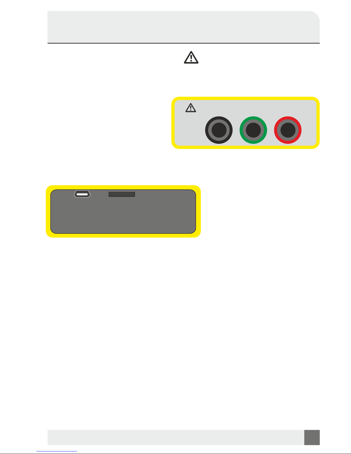
Connections and test leads
Test leads
To connect the measured wire pair shielded CAT III test leads are used with 4 mm
diameter and with the following color code:
n Wire A red
n Wire B green
n Ground GND black
The connection of the test leads
appended to the selected mode.
Side connections
n USB 1-Port for data transfer
n SD Card
Examination of the test leads
Functional test
1. Run before each use of the test device , a visual inspection of the test leads , probes and
Alligator clips are in good condition and undamaged and not cracked Insulation through.
2. Check the consistency of the test cable through solid short-circuit the test leads and reading the
resistor directly on the screen (the resistance should be less than 1.0) .
Terminals of the test cable
The test cables are connected as shown in Figure above. This figure shows the on top lying tester
sockets for the test cable.
Standard test cable
The red, green and black test leads to be plugged into the appropriate sockets on the top of the test
device , which the names + ( B green ), - ( A red) and earth ( E black ) bear (see illustration) The test probe
and alligator clips for connection to the circuit under test are also included.
ABE
-
+
USB 1 SD
Page 8
KURTH ELECTRONIC www.kurthelectronic.de [email protected]
8
Operating Manual
KE2500 Telco Multimeter
OPERATING
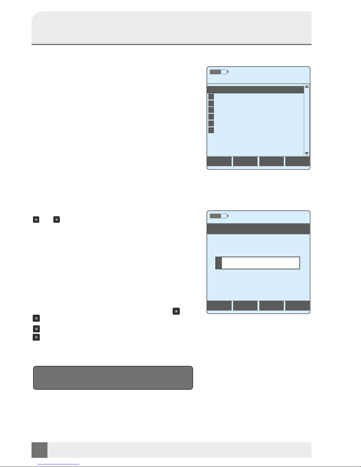
Starting & general rules
The KE3600 works with an operating system that has to be
booted. The boot menu with various device parameters
such as the hardware and software versions appears at the
end of the booting process. You can bring up the Main Menu
immediately by pressing any button.
The user can make basic device settings in the Setup
before starting the measurements.
In most cases, the measurements and settings are selected
using the menu-driven user interface. The vertical control
buttons p+q are used for the selection.
Pressing the SEL key confirms the input or starts the
measurement.
To go to the previous screen or cancel ongoing measurements, press ESC.
Various cable and test parameters can be selected by
pressing the function buttons F1 - F4.
In order to facilitate and speed up the operation, some
modes of measurement can also be selected directly with
the help of the digit keys, e.g. with the key combination
+ in quick succession you can start directly the
Resistance line measurement. The measurements start
immediately after the parameters have been selected.
Save
Some tests have the possibility to save the results. When
available, the memory dialog is called with F4. The file
name is entered using the alphanumeric keyboard. Under
F1 abc ¨123 you can switch between text and number
input, under F2 Clear the entire input can be reset.
Individual digits can be cleared with the control buttons and
F3 DEL. Pressing the backspace key § under F4 deletes
the entry from right to left.
Special characters can be found under the buttons and
.
: . - / @ : _ + , [ ] ; = ?
: # $ % & ‛ ( ) { } ~
With SEL measurement is then stored ultimately under the
file name entered.
Basically, the user should make the on-screen
instructions in each measurement mode row!
Main Menue
Line Multimeter
Remote Switch Type
Remote Switch Functions
Cable Parameter
Date / Time
Date / Time
1
2
3
4
5
6
Allow USB Access
7
Setup
Loop Analysis
<KE90X>
abc"123 Clear DEL
f
Filename
*
*
#
#
1
2
ABC
Page 9
Operating Manual
Telco Multimeter KE2500
KURTH ELECTRONIC www.kurthelectronic.de [email protected]
9
Line Multimeter
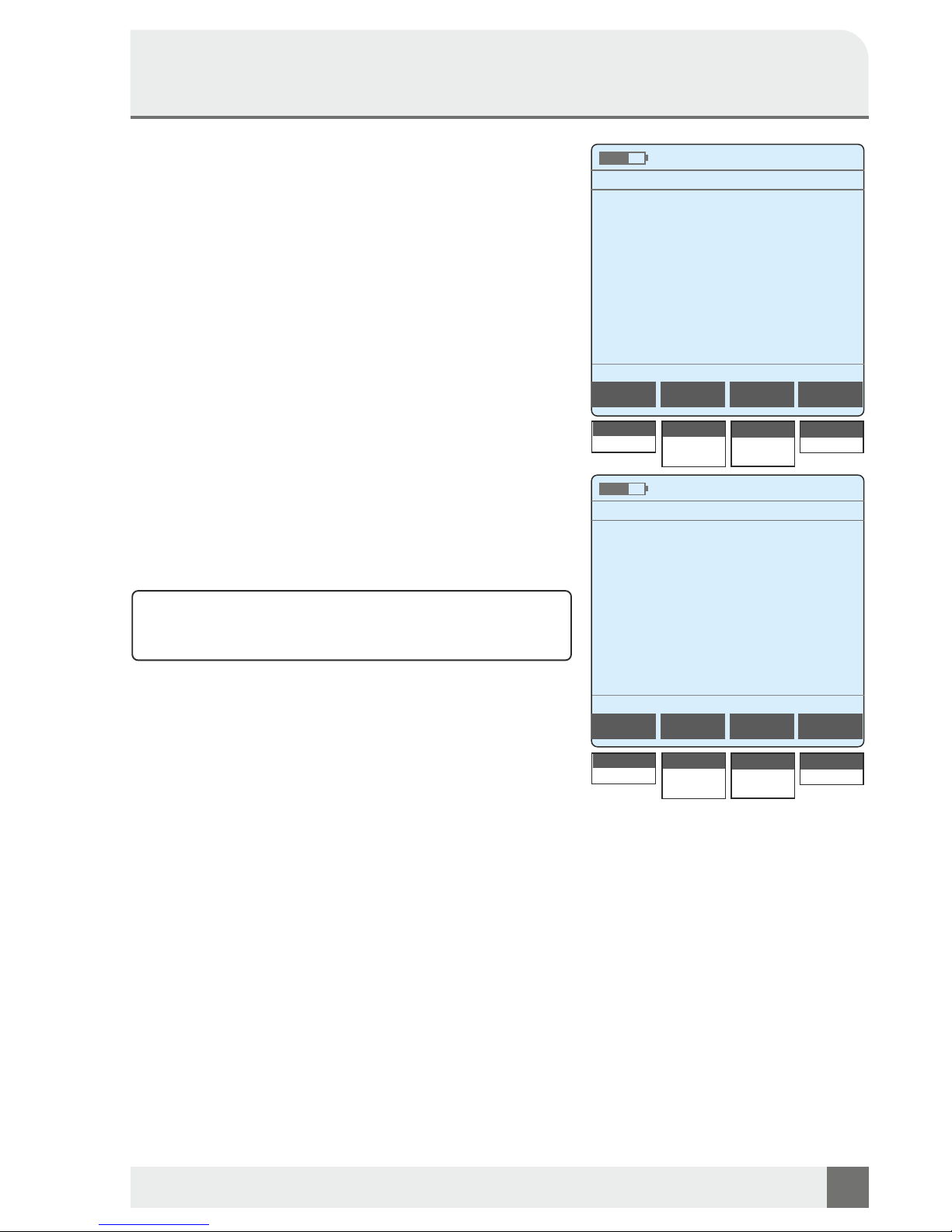
1.1 Voltage
The purpose of this study is to measure the direct and the
alternating voltage: in the AC range only the alternating
voltage is displayed, the direct voltage and the rms value (DC
+ AC) are displayed in the DC range.
Measuring method
Connect the wires to be measured and the shield of the cable.
Select the Voltage mode and press SEL. The measurement is
then started automatically. The results of the alternating and
direct voltage are displayed numerically in volts and the
frequency in Hz.
With F1, the min / max values can be switched on or off for
easier assessment. Under F2 Probe the measurement points
can be selected from the differential voltage measured
between two cores of a pair of conductors (A-B) and the
common-mode voltage measured between a pair of
conductors and the ground (A-GND, B-GND). With F3, the
measuring ranges can be switched between DC (DC voltage)
and AC (AC voltage) and AC TP (AC voltage with low-pass
filter> 200 Hz). Under F4 Term, the input resistance is reduced
from 10 MW to 120 kW to measure the actual voltage.
Safety note:
The measured voltage must not exceed the value of 600 V
for phase to ground or phase to phase.
Voltage
Voltage
DC:
AC/DC:
AC:
Probe
Probe
0,005 V
0,023 V
0,123 V
Date / Time
Date / Time
f:
f:
49,98 Hz
49,98 Hz
A - B
A - B
Area
Area
AC
DC
Term
Term
None
None
A - B
A - GND
B - GND
A - B
A - GND
B - GND
AC
AC LP
DC
DC
AC
AC TP
None
120 kW
None
120 kW
min: 0,003 V
min: 0,118 V
max: 0,005 V
max: 0,124 V
On
Off
On
Off
min/max
min/max
On
An
Page 10
Operating Manual
KE2500 Telco Multimeter
KURTH ELECTRONIC www.kurthelectronic.de [email protected]
10
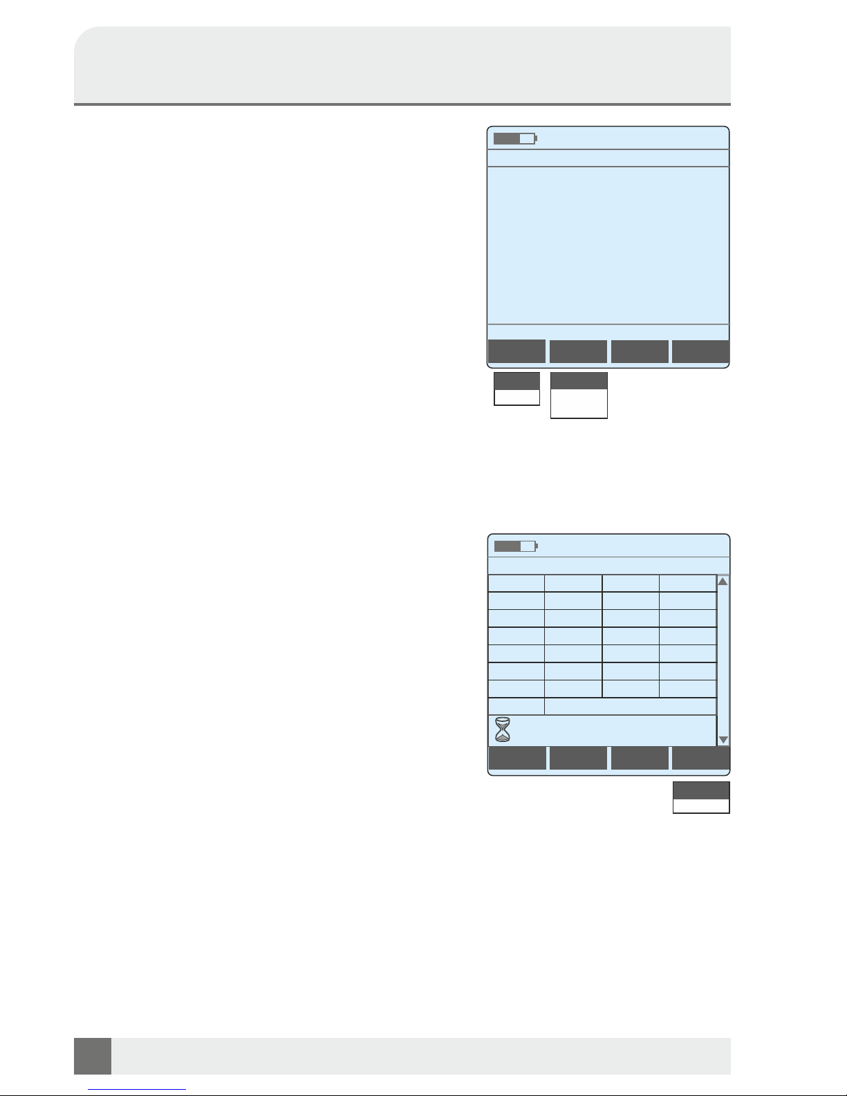
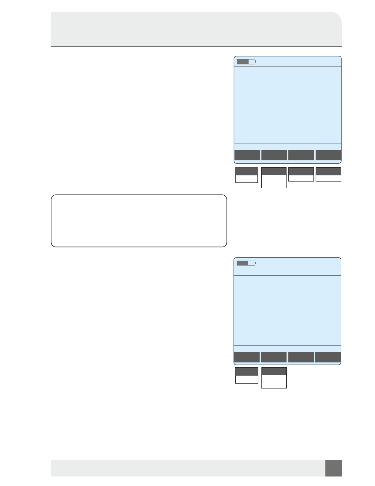
1.2 Resistance line
The purpose of this measurement is the determination of the
loop resistance.
Measuring method
Connect the wires to be measured and the shield of the cable.
The far end of the pair of wires to be measured must be shortcircuited, work with a 2nd person or with the KE90X Remote
Unit. Select the Resistance line mode and press SEL. The
measurement is then started automatically. On top of the
dispaly the used cable is shown. The measuring result is
shown in ohms and the cable length in meters.
Under F1, you can show or hide the min / max values. With F2
Probe you can select the measuring point. The measurement
points can be selected, e.g. between two wires of a wire pair
(A-B) and between a wire and ground (A-GND, B-GND).
Please ensure that the cable is voltage-free before
measurement!
1.3 Resistance line balanced
Determination of the loop resistors A-B and the resistors AGnd, B-Gnd. The cable length, the earth line resistance, the
resistance difference (WU) and the maximum resistance
difference (WUmax *) as well as the unbalance are displayed.
The selected cable parameter is displayed at the bottom of the
table.
Autom. Measuring procedures (only possible with
remote KE90X and TX915) see Resistance line.
Please ensure that the cable is voltage-free before
measurement! The measuring points are automatically
tested in sequence with the aid of the remote measuring
devices. The result can be displayed as a QR code (key F3,
see page 14) or stored for later evaluation (key F4).
For more information, see 7. Allow USB Access on page 20.
* The maximum permissible WU depends on the length and diameter
of the cable.
Resistance line
Basic V/2=100us 0.6mm C 0.042nF
Date / Time
5,4 Ω
43,1 m
min: 5,3 W
max: 5,5 Ω
Probe
A - B
A - B
A - GND
B - GND
min/max
On
Off
On
Resistance line balanced
Date / Time
Save
A-BRaRb
R
5.571 Ohm
2.892 Ohm
2.742 Ohm
L(R)
43.80 m
RE
2.664 Ohm
WU
0.150 Ohm
WUmax
0.215 Ohm
Unsym
5.2 %
CU
Basic V/2=100us 0.6mm C 0.042
connect to remote
please wait ...
Save
Stop
QR-Code
Page 11
Operating Manual
Telco Multimeter KE2500
KURTH ELECTRONIC www.kurthelectronic.de [email protected]
11
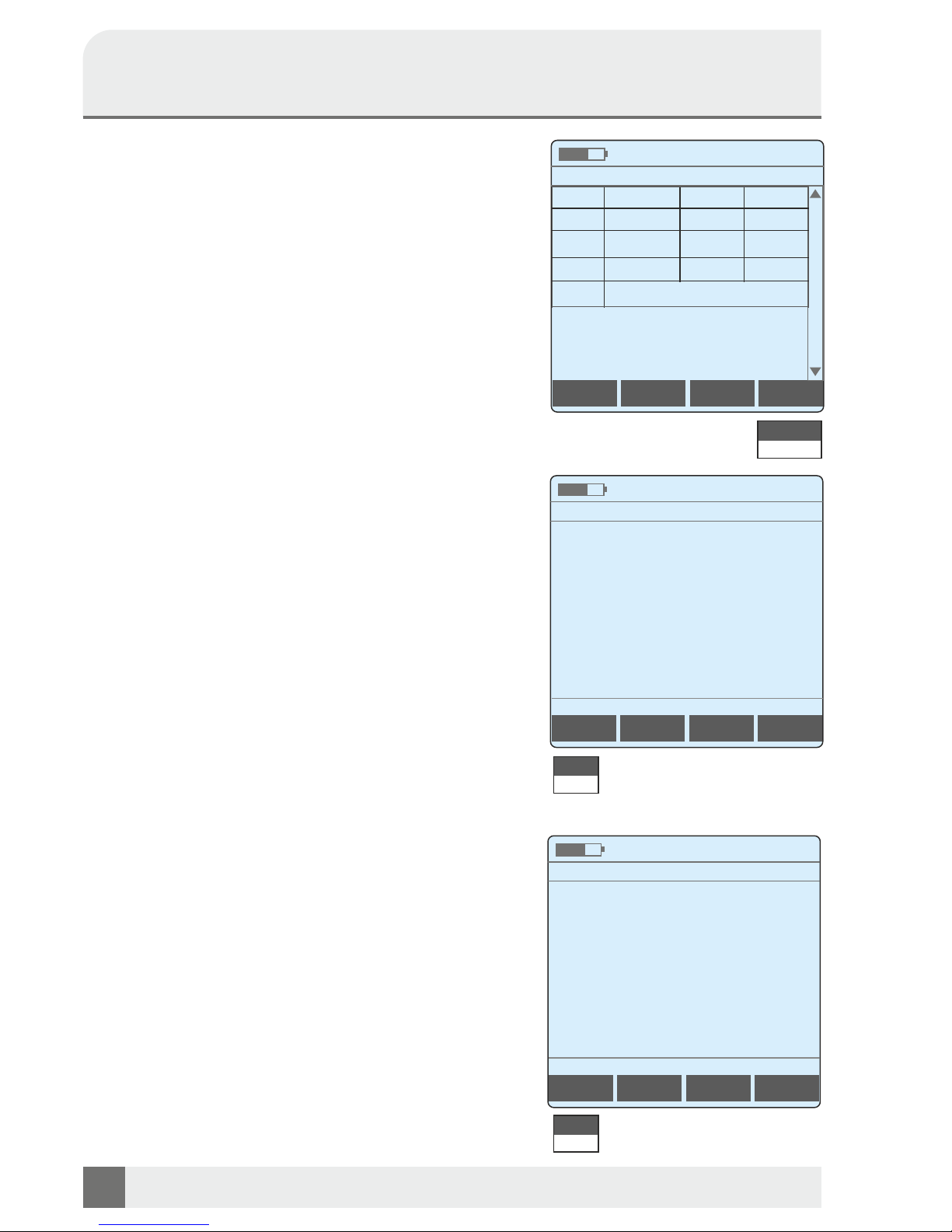
1.4 Insulation
In this setting KE2500 measures the insulation resistance
between the two wires running a pair of wires and the individual
wires and ground.
Measurement method
Connect the wires to be measured and the shield of the cable.
Select Insulation and press SEL. The measurement starts
automatically thereafter. The results are displayed in Ohm.
With F1, the min / max values can be switched on or off for easy
assessment.
F2 can be selected from the individual operating resistors such
as two cores of a wire pair (A-B) and between a wire pair and
the ground (A-GND, B-GND).
Under F3 Test V the test voltage at A-B can be changed from
100 V to 8 V. Reason: In order to be able to measure the
insulation also on lines with terminated ISDN / NTBA. For AGND, B-GND, a test voltage of 100 V is always present.
The polarity can be reversed with F4.
Safety note:
The tests of insulation resistance occur at high DC
voltages. There is the risk of electric shock when touching
conductive parts. When performing a test of the insulation
resistance always follow the safety precautions and make
sure that you follow the precautions for safety at work.
1.5 Capacitance
The purpose of the measurement is to determine the operating
capacity of a wire pair. The measurement shows whether the
line is open and shows the typical input capacitance of
connected devices as well as asymmetries of the conductor
pair.
Measuring method
Connect the wires to be measured and the shield of the cable.
The far end of the pair of wires to be measured must be open!
Select th e C a p a citance m o de and press SE L . T he
measurement is then started automatically. The display shows
on the top the cable parameters used for this measurement.
The capacity and the resulting cable length are displayed.
With F1, the min / max values can be switched on or off for the
assessment of fluctuations.
Under F2 measuring points the measuring points can be
selected.
Capacitance
1,67 nF
38,6 m
Date / Time
Probe
A - B
A - B
A - GND
B - GND
Insulation
5,116 MΩ
Date / Time
Probe
A - B
A - GND
B - GND
A - B
Test V
100 V
Polarity
Normal
100 V
8 V
Basic V/2=100us 0.6mm C 0.042nF
Normal
Invers
min/max
min/max
On
On
On
Off
On
Off
min: 5,101 MΩ
min: 0,54 nF
max: 5,120 MΩ
max: 1,78 nF
Page 12
LCL 1 MHz
Longitudial Conversion Loss
Date / Time
51,78 dB
f: 1,00 MHz
min/max
min: 50,18 dB max: 56,21 dB
1.6 Capacity balanced
Determination of capacities of the A and B wires, A wire to earth
and B wire to earth, the resulting cable length and the symmetry
values. Under CU, the set cable parameter is displayed.
Measuring method
See Capacity. The measuring points are automatically tested in
series. The result can be displayed as a QR code (key F3, see
page 14) or stored for later evaluation (key F4).
For more information, see 7. Allow USB Access on page 20
1.7 Ground return resistance
Here the resistance of the ground-return is measured, for the
evaluation of defective or missing shields or corroded terminals.
Measuring method
Connect the wires to be measured and the shield of the cable.
Select the earthing resistance mode and press SEL. The
measurement is then started automatically. The display shows
the cable parameter used. Measurement results are displayed
in Ohms.
With F1, the min / max values can be switched on and off, the
absolute value is not necessarily meaningful, but high
fluctuations indicate errors.
1.8 LCL 1 MHz* (Longitudial Conversion Loss)
In the case of the asymmetry measurement (LCL), the balance
between the A wire to ground is compared with that of the B wire
to ground. For this purpose, a signal with 1 MHz is fed
symmetrically to the wires in relation to the ground. The voltage
measured at A + B is the indicator of the unbalance. The higher
the dB value, the lower the unbalance.
With F1, the min / max values can be displayed and dimmed to
view fluctuations.
Measuring method
Connect the wires to be measured and the shield of the cable.
Select the operating mode LCL 1 MHz and press SEL. The
measurement is then started automatically.
* LCL Measurement according to ITU G.117
Operating Manual
KE2500 Telco Multimeter
KURTH ELECTRONIC www.kurthelectronic.de [email protected]
12
Capacity balanced
Date / Time
Save
A-B
A-GND
B-GND
C
1.6 nF
1.9 nF
1.9 nF
L(C)
38.09 m
Sym
0.0 %
0.000nF
CU
Basic V/2=100us 0.6mm C 0.042
Ground return resistance
Basic V/2=100us 0.6mm C 0.042nF
Date / Time
5,4 W
min/max
On
On
Off
On
Off
Save
Stop
min: 3,1 W
max: 5,6 W
QR-Code
On
Page 13
KURTH ELECTRONIC www.kurthelectronic.de [email protected]
13
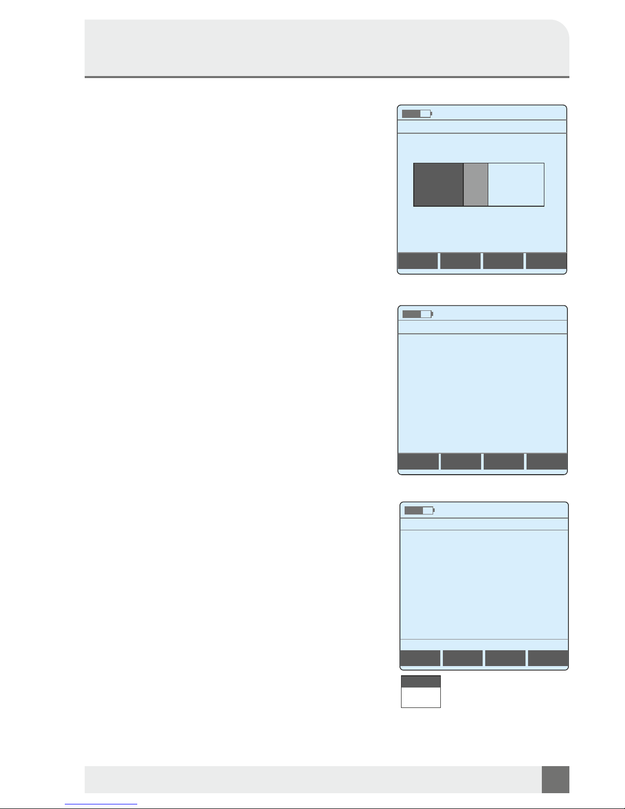
1.9 PPA and Signature detection
With the PPA detection (Passive test completion), it is possible to
check whether a TAE of the Deutsche Telekom is properly
installed on the subscriber side. The PPA is installed in the first
TAE at the participant. With the help of the PPA the Telekom can
measure the line into the house to the 1. TAE and thus detect
possible errors.
The Signature is a feature of the DSL connection cable supplied
by Deutsche Telekom together with DSL routers for the All-IP
connection.
With the Signature detection can be checked whether the
subscriber has the DSL router from the Telekom properly
connected with the cable provided to the TAE socket.
The detection can be canceled with ESC.
Possible results:
- PPA not recognized
- Signature not recognized
- PPA A-B detected
- PPA inverse detected
- Signature detected
- PPA detection is not unique
- Signature not recognizable
- Signature not recognized, PPA present
- 2 or more PPA A-B detected
- 2 or more PPA inverse detected
- 2 x PPA antiparallel suspected
- Resistance A-B and B-A too small
1.10 Current
In this setting, the KE2500 measures the DC (DC) and AC (AC)
currents. This makes it possible to assess whether the available
power is sufficient for ISDN or analogue connections.
Measuring method
Connect the wires to be measured and the shield of the cable.
Select the Current mode and press SEL. The measurement is
then started automatically. The results of the measurement of
alternating and direct current are shown in amperes. Under F1
measuring points. The measurement points can be selected,
e.g. (A-B) and between a pair of wires and the ground (A-GND,
B-GND).
1.12 Insulation (quick)
As 1.5 Isolation, a filter accelerates the measurement, other
settings see 1.4 Isolation (Page 11).
PPA-Signature-Detection
Detection running
Date / Time
PPA-Signature-Detection
Date / Time
PPA A-B detected
Operating Manual
Telco Multimeter KE2500
Current
DC:
AC:
Date / Time
Probe
A - B
A - GND
B - GND
0,000 A
A - B
0,004 A
Signature not
recognizable
Page 14
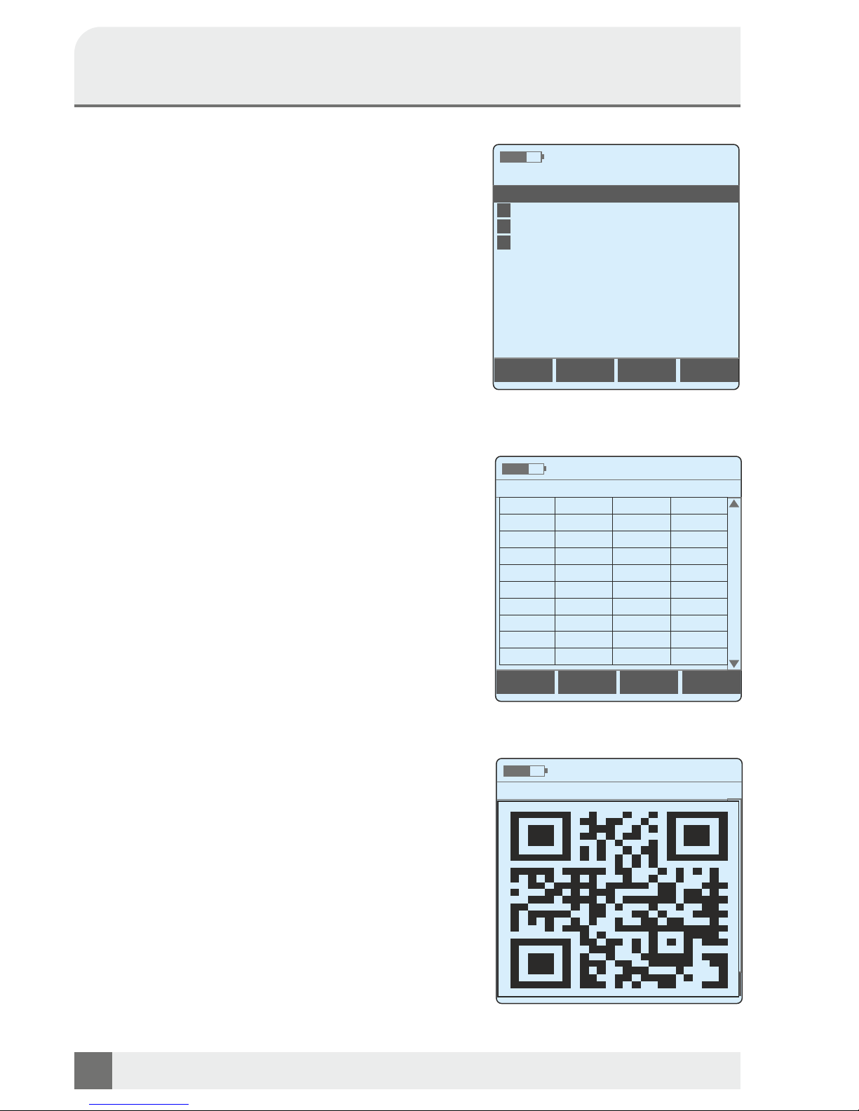
2. Loop Analysis
Loop analysis is a measurement method that summarizes
and automates the most important measurements, in order
to simplify and speed up the test sequences. In the main
menu you have to set the measuring aid to be used.
You can choose between:
KE90X (with acknowledgment of switching commands)
TX915 (reduced functions)
or Manual (manual switch).
2.1 Loop Analysis w/o CO
The loop analysis without the exchange refers to a recently
released line that is separate from the central office.
Measurement method
Connect the wires to be measured and the shield of the
cable. Select Loop analysis without C.O. and press SEL.
The measurement starts automatically thereafter.
Follow the coming instructions shown in the display.
First every measuring point combinations (A-B, A-GND and
B-GND) successively established the current levels of direct
and alternating current, followed by the measurement of the
DC and AC voltages, the resistance measurements and the
length resulting from the resistance, capacity, the length
resulting from the capacitance and finally the insulation
resistance.
With F4 Stop, the measurement can be frozen and then left
completely with ESC.
After the measurement has been completed, a QR code with
the measured values can be generated and displayed with
F3 QR code. This can then simply be read in with a QR
application. ESC exits the view and test.
Alternatively, the measured values can also be stored as a
CSV file under F4 for later evaluation.
For more information, see 7. Allow USB Access on page 20.
Loop Analysis w/o CO
Loop Analysis w/o CO
Date / Time
Date / Time
A-B
A-GND
B-GND
I=
0.1 mA
0.1 mA
0.1 mA
I~
0.5 mA
0.4 mA
0.4 mA
U=
0.0 V
0.0 V
0.0 V
Ueff
0.0 V
0.0 V
0.0 VR>MAX
>MAX
>MAX
L(R)=
>MAX
C
0.0 nF
0.0 nF
0.0 nF
L(C)=
0.000 m
Riso
>20G
>20G
>20G
Speichern
Loop Analysis
Loop Analysis w/o CO
Loop Analysis with CO
Loop Analysis (auto)
TAL R, C , ISO & LCL mit Messhelfer
Date / Time
1
2
3
4
Operating Manual
KE2500 Telco Multimeter
KURTH ELECTRONIC www.kurthelectronic.de [email protected]
14
Stop
Display results
Selection of different autom.
line measurements
Embedded QR code with the
measurement results
QR-Code
A-B
A-GND
B-GND
I=
0.1 mA
0.1 mA
0.1 mA
I~
0.5 mA
0.4 mA
0.4 mA
U=
0.0 V
0.0 V
0.0 V
U~
0.0 V
0.0 V
0.0 V
R
>MAX
>MAX
>MAX
L(R)=
>MAX
C
0.0 nF
0.0 nF
0.0 nF
L(C)=
0.000 m
Riso
>20G
>20G
>20G
Page 15
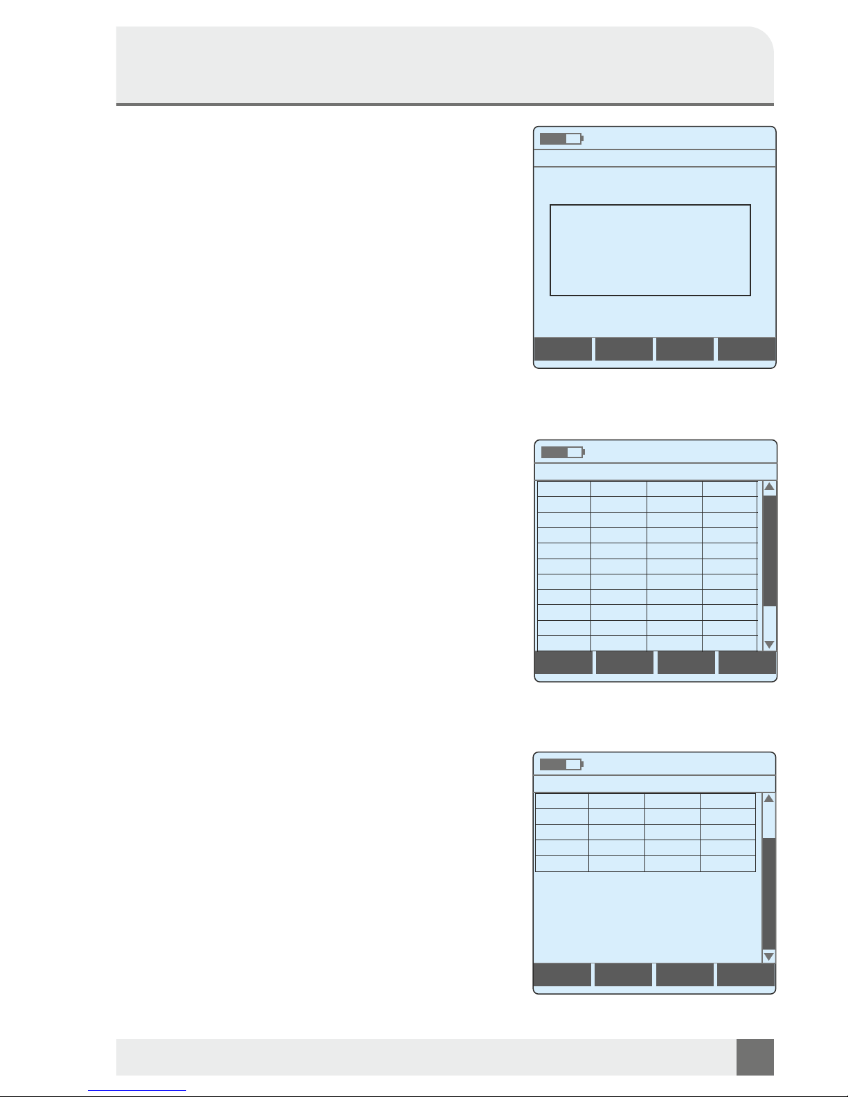
2.2 Loop Analysis with CO
The loop analysis is a measurement technique that
summarizes and automates the most important measurements so the test procedures are simplified and accelerated.
The loop analysis with CO refers to a recently released line
that must be connected to the central office, however,
separated from the central office for some measurements.
This will be passed in clear-screen instructions to the user.
Measurement method
Connect the wires to be measured and the shield of the cable.
Select Loop analysis with CO and press SEL. The
measurement starts automatically thereafter.
Follow the coming instructions shown in the display.
First, for every measuring point (A-B, A-GND, B-GND)
successively the currents for DC and AC identified in
connection to the central office, followed by the measurement
of the DC and AC voltages, also in connection to the central
office. Now, the line has to be separated from the central
office, and the measurements of current and voltage is
repeated. Then place a loop A-B, followed by the measurements of resistance and the cable length as a result of
resistance. Resistance measurements, and the resultant of
the resistive length, capacitance, the length resulting from the
capacitance and the end of the insulation resistance. Then a
loop A-B-GND has to be insert, measurements to the
capacitance and the cable length as a result of capacitance,
as well as the insulation resistance follows.
With F4 Stop, the measurement can be frozen and then left
completely with ESC.
After the measurement has been completed, a QR code with
the measured values can be generated and displayed with F3
QR code. This can then simply be read in with a QR
application. ESC exits the view and test.
Alternatively, the measured values can also be stored as a
CSV file under F4 for later evaluation.
For more information, see 7. Allow USB Access on page 20.
Loop Analysis with CO
Loop Analysis with CO
Date / Time
Date / Time
Loop Analysis with CO
Loop A/B/GND
Date / Time
A-B
A-GND
B-GND
ESC " Continue SEL " Remote
Save
Operating Manual
Telco Multimeter KE2500
KURTH ELECTRONIC www.kurthelectronic.de [email protected]
15
Example of Screen dialog
QR-Code
Stop
A-B
A-GND
B-GND
I= CO
0.1 mA
0.1 mA
0.1 mA
I~ CO
0.5 mA
0.4 mA
0.4 mA
U= CO
0.0 V
0.0 V
0.0 V
U~ CO
0.0 V
0.0 V
0.0 V
I=
0.1 mA
0.1 mA
0.1 mA
I~
0.5 mA
0.4 mA
0.4 mA
U=
0.0 V
0.0 V
0.0 V
U~
0.0 V
0.0 V
0.0 V
R
>MAX
>MAX
>MAX
L(R)=
>MAX
R
>MAX
>MAX
>MAX
L(R)=
>MAX
C
0.0 nF
0.0 nF
0.0 nF
L(C)=
0.000 m
Riso
>20G
>20G
>20G
Page 16
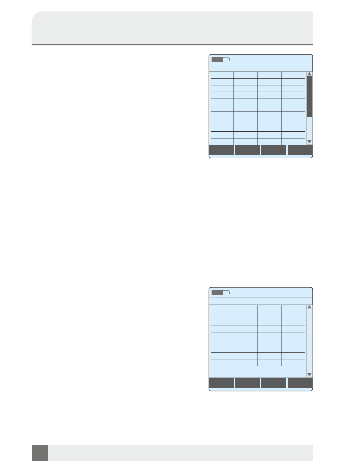
2.3 Loop Analysis (auto)
The loop analysis is a measurement technique that
summarizes and automates the most important measurements s o the test procedures are simplified and
accelerated. The loop analysis (auto remote) will perform
the line switching using the KE900 remote unit.
Measurement method
Connect the wires to be measured and the shield of the
cable. Select Loop analysis (auto) and press SEL.
The measurement starts automatically thereafter.
First, for every measuring point combinations (A-B, A-GND
and B-GND) successively the currents for DC and AC
identified in connection to the office, followed by the
measurement of the DC and AC voltages, also in
connection to the office. The switching functions of the
KE90X now allows direct measurements as shown in 2.2.
Loop Analysis with CO.
With F4 Stop, the measurement can be frozen and then left
completely with ESC. After the measurement has been
completed, a QR code with the measured values can be
generated and displayed with F3 QR code. This can then
simply be read in with a QR application. ESC exits the view
and test. Alternatively, the measured values can also be
stored as a CSV file under F4 for later evaluation.
For more information, see 7. Allow USB Access on page 20.
Date / Time
Date / Time
2.4 Schleifenanalyse (Loop Analysis)
QA8 07/2014
The loop analysis QA8 is a customized, automated analysis
for telecom applications are carried out the required
measurements for the skilled conclusion for AN according to
Annex 8.
Measurement method
Connect the wires to be measured and the shield of
the cable. Select Schleifenanalyse QA8 07/2014 and
press SEL. The measurement starts automatically
thereafter.
These values can then be saved as a CSV file for later
evaluation on a PC or laptop.
For further information see the Loop Analysis before.
Operating Manual
KE2500 Telco Multimeter
KURTH ELECTRONIC www.kurthelectronic.de [email protected]
16
Measurements with measuring aids
such as KE905
Save
QR-Code
Save
QR-Code
Loop Analysis (auto)
A-B
A-GND
B-GND
I= CO
0.1 mA
0.1 mA
0.1 mA
I~ CO
0.5 mA
0.4 mA
0.4 mA
U= CO
0.0 V
0.0 V
0.0 V
U~ CO
0.0 V
0.0 V
0.0 V
I=
0.1 mA
0.1 mA
0.1 mA
I~
0.5 mA
0.4 mA
0.4 mA
U=
0.0 V
0.0 V
0.0 VU~0.0 V
0.0 V
0.0 VR>MAX
>MAX
>MAX
L(R)=
>MAX
Schleifenanalyse QA8 07/2014
A-B
A-GND
B-GND
R
0.653 W
0.671 W
0.645 W
L(R)=
5.141 m
U=
0.0 V
0.0 V
0.0 VU~0.0 V
0.5 V
0.0 V
Riso
<1M
> 3G
> 3G
C
0.3 nF
0.3 nF
0.3 nF
R
>MAX
>MAX
>MAX
L(C)=
5.141 m
Page 17
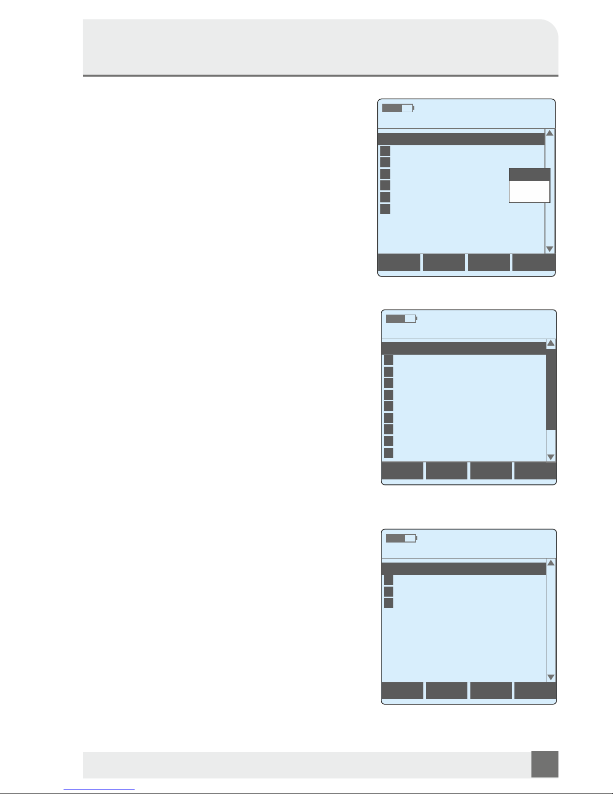
3. Remote Switch Type
Selection of the measuring helper type for (remote)
switching of the copper duplex to be tested. There is the
choice between Kurth Electronic Remote KE900 / KE905
(with acknowledgment of the switching commands) and the
Teletech TX915 (restricted function). Alternatively, the
switching operations can also be carried out manually
4. Remote Switch Functions
With the KE2500 you have the possibility to send control
commands directly from the device to the optional
measuring devices like the KE900 / KE905 and the TX915
remote units. The use of the remote unit for remotecontrolled line measurement allows you to:
n One-man testing, no assistance required
n Used in areas such as underground distribution,
cable shafts, etc. without communication access
n Subscribers' line stay in service until testing starts
and will be restored after
n Remote controlled switching functions such as
cut through, loop, ground and open
n Measurement up to 30 MHz with the use of the device
at the far end
n Ideal for testing dual pairs in preparation for channel
bonding
Possible remote unit modes:
4.1 Trace Tone On/Select
So the trace tone loud speaker will be activated and the
trace tone send from KE900 and the port can be changed.
4.2 Open Ports 1+4
Opens Port 1 and stops tracing tone. Used for measurements like open circuit noise, capacitance, leakage
resistance. Teletech TX915: Open port (OPEN)
4.3 Port 1 Loop
Port 1 pair shorted. Used to measure the loop resistance.
Teletech TX915: A-B-GRD loop (SHORT)
4.4 Port 1 Loop Pulse 3 sec
Port 1 loop pulse for 3 seconds. With it you can clearly detect
the far end with a TDR even the loop is correct terminated on
the CO side.
4.5 Connect Port 1+2
Port 1 connected to Port 2. Used to restore the subscriber's
line before and after testing. Teletech TX915: Switch
through port (EXCHANGE)
4.6 Connect Port 1+3
Port 1 connected to Port 3. A test set on Port 3 can then be
used for end-to-end measurements like attenuation in
conjunction with a additional signal transmitter on the far
end.
Remote Switch Functions
Remote Switch Functions
Trace Tone On/Select
OPEN
SHORT
EXCHANGE
Control functions with KE90X
Control functions with TX915
Date / Time
Date / Time
1
2
3
4
KURTH ELECTRONIC www.kurthelectronic.de [email protected]
17
Operating Manual
Telco Multimeter KE2500
Main Menue
Line Multimeter
Remote Switch Type
Remote Switch Functions
Cable Parameter
Date / Time
1
2
3
4
5
6
Allow USB Access
7
Setup
Loop Analysis
<KE90X>
TX915
KE90X
Manual
Trace Tone On/Select
Open Ports 1+4
Connect Port 1+3
Port 1 Loop
Connect Port 1+4
Port 1 Loop Pulse 3sec
Port 1+4 Loop to GND
Port 4 Loop Pulse 3sec
Connect Port 1+2
Port 1+4 Loop
1
2
6
3
7
4
8
0
5
9
Page 18
4.7 Connect Port 1+4
Port 1 connected with Port 4.
Teletech TX915: Switch through port (EXCHANGE)
2.8 Port 1+4 Loop to Ground
Loop Port 1 and Port 4 and connected to ground e.g. for
resistance symmetrical measurement
2.9 Port 1+4 Loop
Port 1 and Port 4 loop.
2.10 Port 4 Loop Pulse 3 sec
Port 1 and Port 4 loop pulse for 3 seconds. With it you can
clearly detect the far end with a TDR even the loop is correct
terminated on the CO side.
2.11 Connect Port 2+4
Port 4 connected to Port 2. With it you can switch e.g. the
exchange line on another pair of wires.
2.12 Connect Port 3+4
Port 4 connected to Port 3, Port 1 open
2.13 Connect Port 1+2 and 3+4
Port 1 connected to Port 2 and Port 3 connected to Port 4. This
configuration allowes to measure two independent loops for
influence to each other.
Datum / Zeit
Ac kno wle dge sw i tc h ing
commands
The switching commands are sent
from the KE90X with a notification
so that the user can be sure of the
correct test setup.
Operating Manual
KE2500 Telco Multimeter
KURTH ELECTRONIC www.kurthelectronic.de [email protected]
18
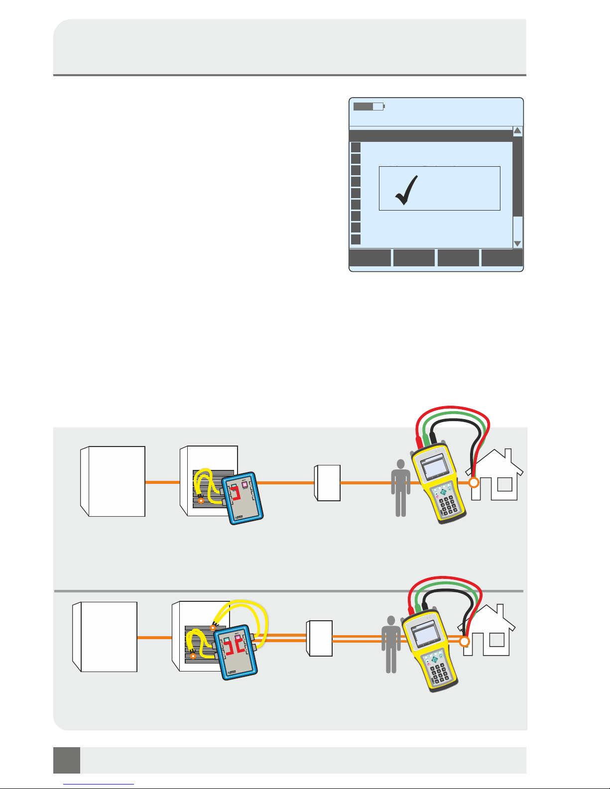
APPLICATIONS WITH KE90X Remote (optional)
KE900
Remote
Cut through: Customers line remains in service up for the start of the
measurement, the customer can continue working.
Open: Measuring e.g. noise, capacity, voltage, insulation, etc.
Customer
CENTRAL
OFFICE
MDF
CCC
KE900
Remote
Customer
CENTRAL
OFFICE
MDF
CCC
Bonding preperation: This configuration alowes to measure two
independent loops for influence to each other
BATT
CHRG
KE2500
T
elco Multimeter
F1
F2
F4
F3
0
*
#
1
2
3
ABC
DEF
4
5
6
GHI
JKL
MNO
7
8
9
PQRS
TUV
WXYZ
ESC
SEL
ON
OFF
Main Menu
Digital Multimeter
KE900 Functions
Copper Parameters
Signature Detection
PPA
Detection
Date / Time
1
2
3
4
5
Allow USB
Access
6
Setup7
BATT
CHRG
KE2500
T
elco Multimeter
F1
F2
F4
F3
0
*
#
1
2
3
ABC
DEF
4
5
6
GHI
JKL
MNO
7
8
9
PQRS
TUV
WXYZ
ESC
SEL
ON
OFF
Main Menu
Digital Multimeter
KE900 Functions
Copper Parameters
Signature Detection
PP
A Detection
Date / Time
1
2
3
4
5
Allow USB Access
6
Setup
7
Remote Switch Functions
Trace Tone On/Select
Open Ports 1+4
Connect Port 1+3
Port 1 Loop
Connect Port 1+4
Port 1 Loop Pulse 3sec
Port 1+4 Loop to GND
Port 4 Loop Pulse 3sec
Connect Port 1+2
Port 1+4 Loop
1
2
6
3
7
4
8
0
5
9
OK!
Page 19
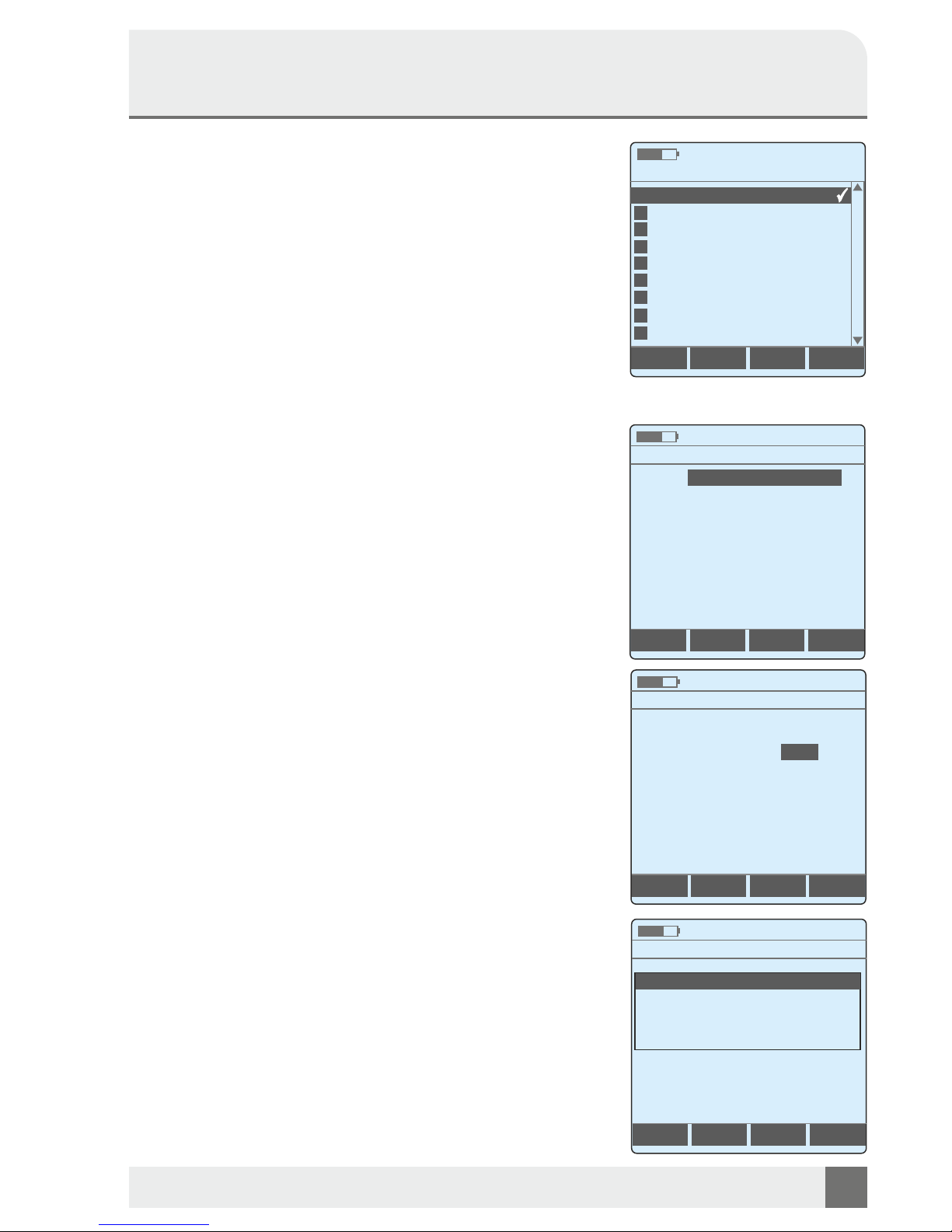
5. Cable Parameters
he most common cable parameters are installed in the device.
1. Basic V/2=100m/µs ø 0.6mm C0.042nF (default)
2. Default V/2=100 Dia=0,4mm C/km
3. A-02Y/0,5/STIII Zell,PE
4. A-02Y/0,8/STIII Zell,PE
5. A-02YSF/0,5/STIII Foam Skin,PE
6. A-02YSF/0,6/STIII Zell,PE
7. A-2Y/0,35/STIII Zell,PE
8. A-2Y/0,8/STIII Papier,Lagen
9. A-2Y/0,9/STIII Zell,PE
10. A-2YF/0,35/STIII Voll,PE
11. A-2YF/0,4/STIII Voll,PE
12. A-PWE/0,4/STIII Papier,Buendel
13. A-PWE/0,6/STIII Papier,Buendel
14. A-PWE/A-PM/0,4/STIII Papier,Lagen
15. A-PWE/A-PM/0,6/STIII Papier,Lagen
16. A2Y/0,4/STIII Voll,PE
17. A2Y/0,6/STIII Voll,PE Tragseil
The cable parameters are transferred to the KE2500 via the file
CUPARAMS.DAT. To do this, set up a USB connection (see page
20) and then copy the file to the directory KE2500: \ SYS \ KECT.
Create new copper cable parameters:
The F2 + key is used to copy a parameter for editing and can then be
edited with F4 Edit. By entering only 2 values - such as the cable
diameter ø and the resistance per meter R '- the KE2500 indepen.dently calculate the remaining copper cable parameters.
Use the left / right control buttons to scroll through the values. The
selected value is then selected with SEL and changed in the context
menu via the numeric keypad.
Make sure that the new settings are saved under a changed label as
the default setting. To change the name go to Name and confirm
with SEL to get to the context menu for the name change, after the
name change confirm with SEL an you will get back to the cable
parameter menu, press F4 Save for conclusion. The new name will
now appear under Cable Parameters in the selection menu.
SEL selects the desired value. This is then marked with a hook at
the right edge of the screen. The F3 DEL button can be used to
remove the cables that are installed.
Cable Parameters
Basic V/2=100m/µs ø 0.6mm C0.042nF
Default V/2=100 Dia=0,4mm C/km=
A-02Y/0,5/STIII Zell,PE
A-02Y/0,8/STIII Zell,PE
A-02YSF/0,5/STIII Foam Skin,PE
A-02YSF/0,6/STIII Zell,PE
A-2Y/0,35/STIII Zell,PE
A-2Y/0,8/STIII Papier,Lagen
A-2Y/0,9/STIII Zell,PE
Date / Time
1
2
3
4
5
6
7
8
9
Cable Parameters
test-kabel-06
Date / Time
Name:
Ø= 0.600 mm
R'= 0.0636 W/m
2
k= 55.600 m/Wmm
V= 200.0 m/µs
VF= 0.66
Save
2
A= 0.282 mm
2R'= 0.1272 W/m
C'= 0.098 nF/m
V/2= 100.0 m/µs
Cable Parameters
Cable Parameters
test-kabel-06
Y(ST)Y_4x2x06
Date / Time
Date / Time
Name:
Name:
Ø= 0.600 mm
Ø= mm0.600
R'= 0.0636 W/m
R'= 0.0636 W/m
2
k= 55.600 m/Wmm
2
k= 55.600 m/Wmm
V= 200.0 m/µs
V= 200.0 m/µs
VF= 0.66
VF= 0.66
Save
Clear
2
A= mm0.282
2
A= 0.282 mm
2R'= 0.1272 W/m
2R'= 0.1272 W/m
C'= 0.098 nF/m
C'= 0.098 nF/m
V/2= 100.0 m/µs
V/2= 100.0 m/µs
Conductor Cross-Section
2
0.282 mm
= •
*
KURTH ELECTRONIC www.kurthelectronic.de [email protected]
19
Operating Manual
Telco Multimeter KE2500
1
a=0.0039 /K
T= 20°C
1
a=0.0039 /K
1
a=0.0039 /K
T= 20°C
T= 20°C
EditDEL+
Predefined copper cable types
Page 20
Operating Manual
KE2500 Telco Multimeter
KURTH ELECTRONIC www.kurthelectronic.de [email protected]
20
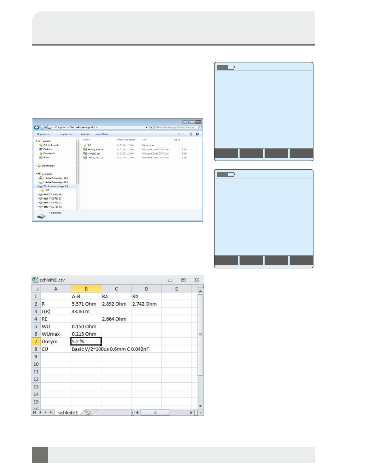
6. Allow USB Access
The stored results (table with measured values in CSV format)
are transferred to a PC or laptop using the USB port. To do this,
you must first enable the USB device on the main menu.
Select Allow USB Access. Now the meter is displayed as a
USB drive on the connected device and the stored files can be
edited. Please do not delete the SYS folder.
Then disconnect the ESC key or Eject using Windows
explorer.
Date / Time
Date / Time
USB Filetransfer
USB Filetransfer
Waiting for PC
PC Connected
Quit with 'Eject'
Quit with ESC or
'Eject' on PC
Example of a loop resistance asymmetry measurement in CSV format
Page 21
KURTH ELECTRONIC www.kurthelectronic.de [email protected]
21
7. Setup (Selection of functions and setting parameters)
7.1 Auto Power Off
Automatic shutoff after the last button is pushed. Setting options: Always on, 3 minutes, 5 minutes,
15 minutes, 30 minutes, 60 minutes. When a test is running and when the power supply is active,
the KE2500 does not shut off even after the time has passed.
7.2 Backlight
Setting options: Always on, always off, 3 minutes.
When the power supply is plugged in, the light is always "ON."
7.3 Language
Here the menu language can be set. The languages German and English are available.
7.4 Date & Time
Date and time setting in 24 hour format. DD.MM.YY HH: MM such as 15:06:13 14:40
7.5 Signals & Display
Here you can find further settings:
1. Keybord Beep On or Off
2. Low Battery Beep On or Off
3. Contrast Level 1 to 30
4. Brightness Level 1 to 7 (1 dark, 7 bright)
5. Messung Ende Ton On or Off
7.6 Show min/max Value
Fading in and out of the min / max values facilitates viewing, since the measured value does not have to
be observed all the time.
7.7 Systeminformation
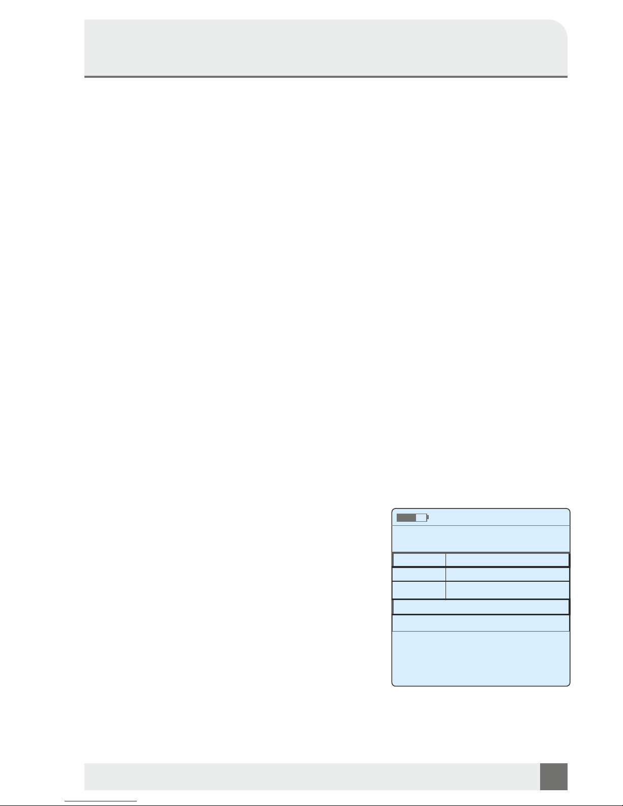
Here you will find information on the built-in modules such
as HW and SW version.
Operating Manual
Telco Multimeter KE2500
Systeminformation
Date / Time
Modul
FW-Version
LPC
1.1-28 DT
KECT
1.28-0
HW-ID
XXXXXXXXXXXXXXX
Page 22
Operating Manual
KE2500 Telco Multimeter
KURTH ELECTRONIC www.kurthelectronic.de [email protected]
22
8. UPDATE VIA USB ACCESS
With the USB interface software updates can be transferred to the base board (LPC) and the
KECT board for installation on the KE2500.
The two components can be installed independently, or in one step.
First sccess from a Windows PC via USB to the internal μSD Card KE2500. The KE2500 behaves
like a USB memory stick.
The installation file (s) now is / are one or both components on the internal μSD Card KE2500
copied and then disconnected logical over the 'Eject' function of Windows.
Attention! The installation of software updates is only started when the KE2500 is powered
by the power pack!
Update the base board (LPC)
The installation of software updates for the base board (LPC) of the KE2500 automatically start
immediately when the installation file is available after the logical 'Eject' on the internal μSD card.
Then the installation file from the internal μSD card is deleted and the KE2500 reboots.
Update the KECT board
After each (re) started KE2500 will determine whether a software update for the KECT board is
present on the internal μSD card. If this is the case, the installation starts automatically and
immediately.
Then the installation file from the internal μSD card is deleted and the KE2500 sets the startup
sequence until the main menu appears.
Attention! The installation of software updates is only started when the KE2500 is powered
by the power pack!
Step by Step:
Transfer of files for software updates on the internal μSD Card KE2500
1. Provide first KE2500 on the power supply with voltage
2. Establish USB connection with the PC
3. KE2500 on (if not already on),
4. In the main menu, select ’Allow USB Access'
5. Click in the Windows dialog screen that appears after a short time on 'Continue Unchecked'
6. Open if necessary. Appears Windows dialog 'Auto Play' to 'folder View files ... 'button
7. Now opens an Explorer window, the contents of the root directory of the internal
μSD Card from the KE2500 is shown.
8 Copy the Installation file(s) of one or both components in the root directory ('SYS') of the
internal μSD Card from the KE2500.
9 Close the Explorer window and the connection via the 'Eject function of Windows
and separate logically.
10 The installation of software updates for the base board (LPC) starts automatically once the
Installation of software updates for the KECT board starts after restarting the KE2500
automatically.
Page 23

KURTH ELECTRONIC www.kurthelectronic.de [email protected]
23
11. Repair and Warrenty
The meter contains devices that are sensitive to static electricity, and the circuit board needs to be
handled with caution. If the protection of a test device was impaired in any way, the device should not be
used further, but be sent in for repair by suitably trained and qualified personnel. The protection of the
tester is likely to be impaired if: there is visible damage, the intended measurement task is not running,
has been stored for a long period of time under adverse conditions, or has been exposed to during
transport heavy loads.
NEW TEST INSTRUMENTS ARE 1 YEAR WARRANTY FROM THE DATE OF YOUR
PURCHASE BY THE USER.
NOTE:
Any unauthorized repair or adjustment of the test device will automatically void the warranty.
Repair and spare parts
If you want the tester to be repaired, contact us at:
Kurth Electronic GmbH
Test & Measurement
Muehleweg 11
72800 Eningen u.A.
Tel: +49-7121-9755-0
Fax: +49-7121-9755-56
E-Mail: [email protected]
To return your product to Kurth Electronic in Germany
1. If a repair is required in a test device, you will be asked to provide the following information to enable
the service department in advance the appropriate receipt of your test device. So that we can provide
you with the best possible service:
n Model, for example, KE2500
n Serial number, for example, 00250
n Reason for the return (eg required repair)
n Details of the error
Operating Manual
Telco Multimeter KE2500
Page 24

Operating Manual
KE2500 Telco Multimeter
KURTH ELECTRONIC www.kurthelectronic.de [email protected]
24
12. Technical Data
Voltage Measuring range ≥ 1 mV to ≤ 600 V (AC, DC, TRMS)
Maximum voltage ≤ 600 V
Input impedance > 9 MΩ DC, > 9 MΩ II <50 pF AC, Low Z ca. 116 kΩ
1
Resolution at 6,000 V 1 mV
1
Resolution at 60 V 10 mV
1
Resolution at 600 V 100 mV
Accuracy DC 0,5 % / AC 1,5 %
Overload protection 600 V AC/DC Sinus permanent
Current Measuring range ≥ 1 mA to ≤ 500 mA (AC, DC, TRMS)
Maximum voltage 950 mA
Input impedance < 0,8 Ω
2
Accuracy DC 0,5 % / AC 1,5 % at > 20 mA
Overload protection 0,95 A shutdown
Resistance Measuring range 0 to 300 kΩ
Resolution 0 .. 3 kΩ 0,1 Ω
Resolution 3 .. 30 kΩ 1 Ω
Resolution 30 ..300 kΩ 100 Ω
Measuring current 0 .. 3 kΩ 2 mA
Measuring current 3 .. 30 kΩ 0,2 mA
Measuring current 30 .. 300 kΩ 20 µA
Accuracy ± 0,5 % to ± 1,5 Ω
Overload protection 600 V AC/DC shutdown
Resistance line Measuring range 0 to 2 kΩ
Resolution 0 .. 2 kΩ 0,1 Ω
Accuracy ± 0,5 % to ± 1,5 Ω
Overload protection 600 V AC/DC shutdown
Insulation 100 V Measuring range 70 kΩ to 2 GΩ
Accuracy 0 .. 100 MΩ 2 %
Accuracy 100 MΩ .. 1GΩ 4 %
Accuracy 1 GΩ .. 2GΩ 8 %
Maximum voltage 120 V
Kurzschlussstrom < 9 mA
Overload protection 600 V AC/DC shutdown
Insulation 8 V Measuring range 1 kΩ to 150 MΩ
Accuracy 0 .. 10 MΩ 2 %
Accuracy 10 MΩ .. 100 MΩ 4 %
Accuracy 100 MΩ .. 150 MΩ 8 %
Maximum voltage 70 V
Short circuit current < 9 mA
Overload protection 600 V AC/DC shutdown
Capacitance Measuring range 0 nF to 3 µF
Input impedance < 24 V ss
Resolution max. 10 pF
Accuracy 0 .. 100 nF 2 % ± 0,2 nF
Accuracy 100 .. 200 nF 2 % ± 0,5 nF
Accuracy 200 .. 400 nF 2 % ± 1 nF
Accuracy 400 nF .. 1 µF 2 % ± 2 nF
Accuracy 1 µF .. 2 µF 2 % ± 4 nF
Accuracy 2 µF .. 3 µF 2 % ± 10 nF
Overload protection 600 V AC/DC shutdown
Device Data Dimensions 22,5 x 11,0/8,0 x 4,0 cm
Weight 700 g
Housing high impact ABS
Display LCD with backlight
Display cover high impact acrylic
Power supply built in batterie
Languages DE, EN
Measurements with current clamps are not permitted
1
Sinusoidal voltage > 5 % of final value 45 Hz .. 65 Hz, > 15 Hz .. 45 Hz or > 65 Hz .. 10 kHz additional error of ±3 % +5 digits.
2
The TRMS converter generates a zero error in the AC measurements up to 30 digit
 Loading...