


Rev H
EDGEGATE / ACCESS
VOIP Gateway
AC- 232-TX / GW-232-SFP
GW-282 / GW- 282S / AC-282
GW- 482S / GW-483S / GW- 483D
H.323, MGCP, SIP
USER GUIDE

Rev H
Revision History
Revision Date Description
C January 2004 Adapted for Version 4.12
D December 2005 Adapted for Version 4.57
E May 2006 Added GW-232. Adapted for Version 5.5
F June 2007 Added GW-483S. Adapted for Version 5.8
G May 2009 Added GW-483D. Adapted for Version 5.10
H December 2009 Adapted for Version 5.11

Rev H
The information in this document is subject to change without notice and describes only the
product defined in the introduction of this document. This document is intended for the use of
customers of Telco Systems only for the purposes of the agreement under which the document is
submitted, and no part of it may be reproduced or transmitted in any form or means without the
prior written permission of Telco Systems. The document is intended for use by professional
and properly trained personnel, and the customer assumes full responsibility when using it. Telco
Systems welcomes customer comments as part of the process of continuous development and
improvement of the documentation.
If the Release Notes that are shipped with the device contain information that conflicts with the
information in the user guide or supplements it, the customer should follow the Release Notes.
The information or statements given in this document concerning the suitability, capacity, or
performance of the relevant hardware or software products are for general informational
purposes only and are not considered binding. Only those statements and/or representations
defined in the agreement executed between Telco Systems and the customer shall bind and
obligate Telco Systems. Telco Systems however has made all reasonable efforts to ensure that
the instructions contained in this document are adequate and free of material errors and
omissions. Telco Systems will, if necessary, explain issues which may not be covered by the
document.
Telco Systems’ sole and exclusive liability for any errors in the document is limited to the
documentary correction of errors. TELCO SYSTEMS IS NOT AND SHALL NOT BE
RESPONSIBLE IN ANY EVENT FOR ERRORS IN THIS DOCUMENT OR FOR ANY
DAMAGES OR LOSS OF WHATSOEVER KIND, WHETHER DIRECT, INCIDENTAL,
OR CONSEQUENTIAL (INCLUDING MONETARY LOSSES), that might arise from the
use of this document or the information in it.
This document and the product it describes are the property of Telco Systems, which is the
owner of all intellectual property rights therein, and are protected by copyright according to the
applicable laws.
Telco Systems logo is a registered trademark of Telco Systems, a BATM Company. BiNOS®,
BiNOSCenter®, T-Marc®, T5 Compact™, T5C-XG™, T-Metro®, EdgeLink®, EdgeGate®,
Access60®, AccessIP™, AccessMPLS™, AccessTDM™, AccessEthernet™, NetBeacon®,
Metrobility®, and OutBurst® are trademarks of Telco Systems.
Other product and company names mentioned in this document reserve their copyrights,
trademarks, and registrations; they are mentioned for identification purposes only.
Copyright © Telco Systems 2009. All rights reserved.


Contacting Technical Support
You can access the most current Telco Systems documentation on the following
site:
http://support.telco.com/.
Access to most of the Telco Systems documentation is password protected. To
obtain a password, contact the Telco Systems support center.
1.1 Technical Support
Telco Systems provides technical assistance for customers and partners. Users can
obtain technical assistance from any of our support centers. Contact information is
provided below:
Web Access:
Email: support@telco.com
BATM Advanced Communications—Main Support Center in Israel
Tel: +972-4-993-5630
Fax: +972-4-993-7926
Telco Systems, A BATM Company—for the Ameri cas
Tel: 1-800-227-0937 (U.S.), 1-781-255-2120 (Outside U.S.)
Fax: 1-781-255-2122
Telco Systems, A BATM Company—for Northern Europe
Tel: +49-241-463-5490
Fax: +49-241-463-5491
Telco Systems, A BATM Company—for Southe rn E urop e (in France)
Tel: +33-15-671-2773
Fax: +33-14-377-1780
http://www.telco.com
Telco Systems, A BATM Company—for Asia Pacific (in Singapore)
Tel: +65-6-725-9901
Fax: +65-6-725-9889
Telco Systems, A BATM Company—for Asia Pacific (in Japan)
Tel: +81-3-5215-5709
Fax: +81-3-5215-5704
5 of 244
Rev H

Contents
1.1 TECHNICAL SUPPORT .................................................................................................................. 5
2 OVERVIEW ................................................................................................................................ 17
2.1 EDGEGATE VOIP GATEWAY 232/282/282S/482S/483S/483D PRODUCT OVERVIEW ............... 18
2.1.1 Features .......................................................................................................................... 21
2.2 LASER SAFETY .......................................................................................................................... 23
2.3 HOW TO GET HELP.................................................................................................................... 23
3 PRE-INS TALLATION REQUIREMENTS ............................................................................. 25
3.1 SUPPORTING EQUIPMENT REQUIREMENTS ................................................................................ 25
3.2 TELEPHONES AND ACCESSORIES ............................................................................................... 25
4 INSTALLATION ........................................................................................................................ 27
4.1 INSTALLING THE EDGEGATE ..................................................................................................... 27
4.2 LINK/ACTIVITY LEDS............................................................................................................... 30
4.3 STATUS LEDS ........................................................................................................................... 30
4.4 SPECIFICATIONS ........................................................................................................................ 31
4.5 INSTALLING THE VOIP GATEWAY GW-482S, GW-282S, GW-483S AND GW-483D ............... 31
4.6 POWER MONITORING ................................................................................................................ 32
5 THEORY OF OPERATION ...................................................................................................... 33
3.1 DIAL PLAN FOR SIP AND H.323 ................................................................................................ 33
5.1.1 Default Dial Plan ............................................................................................................ 33
5.1.2 Dial Plan Syntax ............................................................................................................. 33
5.1.3 Dial Plan Examples ........................................................................................................ 34
5.2 UNDERSTANDING DHCP .......................................................................................................... 35
5.2.1 When Should Clients Use DHCP .................................................................................... 37
5.3 UNDERSTANDING NAT AND NAPT .......................................................................................... 37
5.4 UNDERSTANDING NTP ............................................................................................................. 37
5.4.1 Daylight Saving Time (Summer Time) ............................................................................ 38
5.5 UNDERSTANDING SYSLOG ........................................................................................................ 38
5.5.1 Remote Logging .............................................................................................................. 39
DNS RESOLVER ................................................................................................................... 39
5.7 IP FRAGMENTATION ................................................................................................................. 40
6 IN ITIAL SETUP ......................................................................................................................... 42
6.1 KEYPAD CONFIGURATION (ENABLED ONLY ON 232 GATEWAY PRODUCTS) ............................. 43
6.1.1 Keypad Configuration for MGCP ................................................................................... 43
7 U S ING THE VOIP GATEWAY UNIT ..................................................................................... 45
7.1 FIRST CALL ............................................................................................................................... 45
7.2 PLACING CALLS ........................................................................................................................ 45
7.3 ADDING ADDITIONAL UNITS ..................................................................................................... 45
7.4 ADVANCED CALLING FEATURES FOR SIP ................................................................................. 45
7.4.1 Call Waiting .................................................................................................................... 46
7.4.2 Conference Call .............................................................................................................. 46
7.4.3 Forward a Call ............................................................................................................... 46
7.4.4 Attended Transfer Call ................................................................................................... 46
7.4.5 Blind Transfer Call ......................................................................................................... 46
7.4.6 Hold ................................................................................................................................ 46
7.4.7 Conditional Call Forwarding ......................................................................................... 47
7.4.8 Do Not Disturb (DND) ................................................................................................... 47
7.4.9 Redialing to Last Received Caller .................................................................................. 47
6 of 244
Rev H

7.4.10 Block Last Received Caller ........................................................................................ 47
7.4.11 Auto Redial ................................................................................................................ 47
7.4.12 Block Sending CID per Call ...................................................................................... 47
7.4.13 Anonymous Caller Rejection (ACR) .......................................................................... 47
7.4.14 Support for Pulse Metering per Telephone Line ........................................................ 47
7.4.15 SIP Line Problem Tone Indicator .............................................................................. 47
7.5 ADVANCED CALLING FEATURES FOR H.323 ............................................................................. 48
7.5.1 Call Waiting .................................................................................................................... 48
7.5.2 Conference Call .............................................................................................................. 48
7.5.3 Forward a Call ............................................................................................................... 48
7.5.4 Transfer Call .................................................................................................................. 48
7.5.5 Hold ................................................................................................................................ 48
7.6 ADVANCED CALLING FEATURES FOR MGCP ............................................................................ 49
8 UPGRADING THE GATEWAY FIRMWARE AND DOWNLOADING
CONFIGURATION FILES ................................................................................................................. 51
8.1 DOWNLOADING CODE VERSIONS MANUALLY USING TELNET .................................................. 52
8.2 DOWNLOADING CODE VER SIONS OVER THE WEB VIA THE TFTP SERVER ................................ 53
8.3 DOWNLOADING CODE VER SIONS OVER THE WEB VIA THE HTTP SERVER ............................... 56
8.4 DHCP AUTOMATIC CONFIGURATION ....................................................................................... 60
8.4.1 Setting DHCP Automatic Configuration via the Web ..................................................... 60
8.4.2 Setting DHCP Automatic Configuration via Telnet ........................................................ 61
8.5 FIXED (PROVISIONED) HTTP OR TFTP AUTOMATIC CONFIGURATION ..................................... 62
8.5.1 Setting the TFTP/HTTP Server “Root” Configuration File via the Web ....................... 63
8.5.2 Setting the TFTP Server “Root” Configuration File via Telnet ..................................... 63
8.6 CREATING AND ENCRYPTING CONFIGURATION FILES ............................................................... 64
9 CO NFIGURING THE VOIP GATEWAY VIA TELNET OR CLI CONSOLE .................. 65
9.1 STARTI N G A TELNET SESSION ................................................................................................... 65
9.2 ACCESSING THE CLI ................................................................................................................. 65
10 CLI COMMAND MODES ......................................................................................................... 69
10.1 COMMAND MODES ............................................................................................................... 69
10.1.1 Enable Mode .............................................................................................................. 69
10.1.2 Commands Mode ....................................................................................................... 69
10.1.3 Report Mode .............................................................................................................. 69
10.1.4 Statistics Mode ........................................................................................................... 70
10.1.5 Download Mode ......................................................................................................... 70
10.1.6 Configuration Modes ................................................................................................. 71
10.2 GENERAL COMMANDS ......................................................................................................... 73
10.3 MAIN MODE CLI COMMANDS.............................................................................................. 73
10.4 CONFIG MODE CLI COMMANDS .......................................................................................... 73
10.5 REPORT MODE CLI COMMANDS .......................................................................................... 75
10.6 USING THE CLI COMMANDS ................................................................................................ 75
10.7 CLI COMMAND TREE ........................................................................................................... 76
11 CONFIGURING THE VOIP GATEWAY VIA THE WEB ................................................... 83
11.1 ASSIGN IN G AN IP ADDRES S TO THE VOIP GATEWAY USIN G WEB CONFIGURATION ............ 83
11.1.1 Setting the VoIP Gateway to be a DHCP Client ........................................................ 87
11.1.2 Using VoIP Gateway with a Fixed Address ............................................................... 87
11.2 VOIP PROTOCOL CONFIGURATION ....................................................................................... 87
11.3 AUTOCONFIGURATION ......................................................................................................... 87
11.4 VLAN CONFIGURATION ...................................................................................................... 89
11.4.1 Using VLANs on the VoIP Gateway .......................................................................... 90
11.4.2 VLAN Tagging on the VoIP Gateway ........................................................................ 91
11.4.3 VLAN Configuration Procedure on the VoIP Gateway ............................................. 91
11.5 VOICE AND MANAGEMENT SERVICES CONFIGURATION ....................................................... 93
11.6 IGMP CONFIGURATION ....................................................................................................... 94
11.7 SNMP CONFIGURATION....................................................................................................... 96
12 CONFIGURING SECURITY VIA TH E WEB ........................................................................ 99
7 of 244
Rev H

12.1 DEFAULT SECURITY CONFIGURATION.................................................................................. 99
12.2 SETTING THE PASSWORD ...................................................................................................... 99
12.3 CONFIGURING ADVANCED SECURITY ................................................................................ 100
12.4 SETTING A PASSWORD FOR THE CLI .................................................................................. 102
12.5 ENABLING/DISABLING CONFIGURATION VIA TELNET ........................................................ 103
12.6 USING ACCESS PAGE TO ENABLE USER MODE .................................................................. 103
12.7 INSTALLING AN ENCRYPTION KEY ..................................................................................... 105
12.8 INSTALL ING A GENERAL CONFIGURATION FILE ENCRYPTION KEY .................................... 106
13 MISCELLANEOUS CONFIGURATION VIA THE WEB .................................................. 109
13.1 DEFAULT MISCELLANEOUS CONFIGURATION .................................................................... 109
13.2 CLOCK LOCALIZATION ....................................................................................................... 111
13.3 LOCAL SETTINGS (CALLER ID AND RING FORMAT) ........................................................... 113
13.4 SYSLOG SERVER CONFIGURATION ..................................................................................... 114
13.5 SENDING DEVICE INFORMATION TO THE SYSLOG SERVER ................................................. 115
13.6 PROTOCOL PORTS CONFIGURATION ................................................................................... 115
13.7 SIP ADVANCED CALLING FEATURES AND KEY SEQUENCE CONFIGURATION..................... 117
13.8 RING TONES CONFIGURATION............................................................................................ 121
13.8.1 SIP Distinctive Rings and Call Waiting Tones ........................................................ 122
13.8.2 Ring Names and Distinctive Rings Cadences .......................................................... 122
13.8.3 Call Waiting Tone Cadence Patterns ....................................................................... 124
13.8.4 Call Progress Ton es ................................................................................................. 125
13.8.5 Rings and Tones detailed Format Description ........................................................ 127
13.9 FIBER OPTIC CONFIGURATION ........................................................................................... 128
13.10 COMPLETING THE VOIP GATEWAY CONFIGURATION ........................................................ 129
14 PROTOCOL H.323 CONFIGURATION VIA WEB ............................................................ 131
14.1 DEFAULT H.323 CONFIGURATION ...................................................................................... 131
14.2 SETTING THE H.323 CONFIGURATION ................................................................................ 131
14.2.1 H323 Gatekeeper Settings ........................................................................................ 132
14.2.2 Gateway Settings ...................................................................................................... 132
14.3 DTMF SIGNALING ............................................................................................................. 133
14.4 AUDIO/CODEC CONFIGURATION ...................................................................................... 134
14.4.1 Default Audio/CODEC Configuration Settings ....................................................... 134
15 MEDIA GATEWAY CONTROL PROTOCOL (MGCP) CONFIGURATION VIA WEB
137
16 SESSION INITIATION PROTOCOL (SIP) CONFIGURATION VIA WEB .................... 143
15.1 MGCP CONFIGURATION .................................................................................................... 137
15.2 OUT OF BAND (OOB) SIGNALLING (CONFIGURING RTP TELEPHONE EVENTS) ................. 138
15.3 AUDIO/CODEC CONFIGURATION ...................................................................................... 141
16.1 DEFAULT SIP CONFIGURATION, SIP EXTENSIONS, LINE CONFIGURATION ........................ 143
16.2 SIP EXTENSIONS ................................................................................................................ 146
16.3 LINE CONFIGURATION ........................................................................................................ 149
16.3.1 OOB RTP Telephone Event Signalling .................................................................... 151
16.3.2 Call Forward Configuration .................................................................................... 152
16.3.3 Gain Control Configuration .................................................................................... 152
16.4 PHONE BOOK CONFIGURATION .......................................................................................... 152
16.5 AUDIO/CODEC CONFIGURATION ...................................................................................... 153
16.6 SELECT IN G A PREFERRED CODEC FOR SIP ....................................................................... 154
17 SNMP MANAGEMENT OVERVIEW ................................................................................... 157
17.1 NETWORK MANAGEMENT STATION SETUP ........................................................................ 157
18 RSTP CONFIGURATION VIA TELNET/CLI ..................................................................... 159
18.1 CONFIGURING RSTP .......................................................................................................... 162
18.2 RSTP CONFIGURATION COMMANDS .................................................................................. 163
18.2.1 enable/disable RSTP ................................................................................................ 163
18.2.2 show ......................................................................................................................... 164
8 of 244
Rev H

18.2.3 priority ..................................................................................................................... 164
18.2.4 hello-time ................................................................................................................. 165
18.2.5 forward-delay........................................................................................................... 165
18.2.6 max-age .................................................................................................................... 165
18.2.7 interface ................................................................................................................... 166
18.2.8 force-version ............................................................................................................ 167
18.2.9 help .......................................................................................................................... 167
18.2.10 list ............................................................................................................................ 168
18.2.11 end............................................................................................................................ 168
18.2.12 exit............................................................................................................................ 168
18.2.13 quit ........................................................................................................................... 169
19 NETWORK CONFIGURATION VIA TELNET/CLI .......................................................... 171
19.1 DEFAULT LAN CONFIGURATION ....................................................................................... 171
19.2 NETWORK CONFIGURATION COMMANDS ........................................................................... 171
19.2.1 Enabling DHCP ....................................................................................................... 172
19.2.2 Setting the IP Address of the LAN Interfaces ........................................................... 173
19.2.3 Setting the Subnet Mask of the LAN Interface.......................................................... 173
19.2.4 Setting the IP Address of the Default Gateway ........................................................ 173
19.2.5 Setting the IP Address of the DNS Server ................................................................ 174
19.2.6 Setting the Automatic Configuration ID .................................................................. 174
19.2.7 Enabling the Use of DHCP Options 66, 67 ............................................................. 175
19.2.8 Enabling the Auto Config Mode............................................................................... 175
19.2.9 Setting the TFTP/HTTP Server IP Address ............................................................. 175
19.2.10 Setting the File Name ............................................................................................... 176
19.3 LAN DISPLAY COMMANDS ................................................................................................ 176
19.3.1 Displaying All LAN Configuration Parameters ....................................................... 177
19.3.2 Displaying the IP Address of the LAN Interface ...................................................... 177
19.3.3 Displaying the Subnet Mask of the LAN Interface ................................................... 178
20 SECURITY CONFIGURATION VIA TELNET/CLI ........................................................... 179
20.1 DEFAULT SECURITY CONFIGURATION................................................................................ 179
20.2 SECURITY CONFIGURATION COMMANDS ........................................................................... 179
20.2.1 Accessing LAN Configuration Mode ........................................................................ 180
20.2.2 Enabling Advanced Sec ur i ty .................................................................................... 180
20.2.3 Enabling DHCP Security ......................................................................................... 180
20.2.4 Setting Management IP Addresses ........................................................................... 181
20.3 SECURITY DISPLAYING COMMANDS .................................................................................. 181
20.3.1 Displaying All Security Parameters ......................................................................... 182
20.3.2 Displaying the Advanced Security Status ................................................................. 182
20.3.3 Displaying the DHCP Security Status ..................................................................... 182
20.3.4 Displaying Management IP Addresses .................................................................... 183
21 HTTP CONFIGURATION VIA TELNET/CLI .................................................................... 185
21.1 DEFAULT HTTP CONFIGURATION ...................................................................................... 185
21.2 HTTP CONFIGURATION COMMANDS ................................................................................. 185
21.2.1 Accessing HTTP Configuration Mode ..................................................................... 185
21.2.2 Enabling/Disabling Configuration via HTTP .......................................................... 186
21.3 HTTP DISPLAYING COMMANDS ........................................................................................ 186
21.3.1 Entering into HTTP Configuration Mode ................................................................ 186
22 CONFIGURING VLANS VIA TELNET/CLI ....................................................................... 187
22.1 DEFAULT VLAN CONFIGURATION..................................................................................... 187
22.2 VLAN CONFIGURATION COMMANDS ................................................................................ 187
22.2.1 Accessing VLAN Configuration Mode ..................................................................... 188
22.2.2 Enabling/ Disabling VLANs ..................................................................................... 188
22.2.3 Creating a New VLAN ............................................................................................. 189
22.2.4 Deleting an Existing VLAN ...................................................................................... 189
22.2.5 Adding Ports to a VLAN and Setting the Port’s Default VLAN ............................... 189
22.2.6 Removing Ports from a VLAN .................................................................................. 190
9 of 244
Rev H

22.2.7 Assigning VLAN and Priority Tag to the Management Packets .............................. 190
22.2.8 Assigning VLAN and Priority Tag VoIP Call Session Start Frames ....................... 190
22.2.9 Assigning VLAN, Priority Tag and ToS to the Outgoing RTP Frames .................... 191
22.3 VLAN DISPLAY COMMANDS ............................................................................................. 191
22.3.1 Displaying the VLAN Configuration ........................................................................ 191
22.3.2 Displaying the Service VLAN Configuration ........................................................... 192
23 IGMP CONFIGURATION VIA TELNET/ CLI .................................................................... 193
23.1 DEFAULT IGMP CONFIGURATION ...................................................................................... 193
23.2 IGMP COMMANDS ............................................................................................................. 193
23.2.1 Accessing IGMP Configuration Mode ..................................................................... 194
23.2.2 Enabling/ Disabling IGMP ...................................................................................... 194
23.2.3 Setting Immediate Leave (One Host to Send IGMP Multicast Groups Reports) ..... 194
23.2.4 Setting Proxy IP ....................................................................................................... 195
23.2.5 Setting Minimum Query Interval.............................................................................. 195
23.2.6 Setting Query Interval Last ...................................................................................... 195
23.2.7 Setting Query Count Last ......................................................................................... 196
23.2.8 Setting IP Multicast Flooding .................................................................................. 196
23.2.9 Setting Minimum and Maximum IP Non-Flooding .................................................. 196
23.2.10 Show Value of Any of All IGMP Parameters ........................................................... 197
24 INTERFACE CONFIGURATION VIA TELNET/CLI ........................................................ 198
24.1 DEFAULT INTERFACE CONFIGURATION .............................................................................. 198
24.2 INTERFACE CONFIGURATION COMMANDS .......................................................................... 198
24.2.1 Accessing Interface Configuration Mode ................................................................. 198
24.2.2 Setting the Interface’s State ..................................................................................... 199
24.2.3 Setting the Interface’s Duplex Speed ....................................................................... 199
24.2.4 Enabling Flow Control on the Interface .................................................................. 200
24.3 INTERFACE DISPLAYING COMMANDS ................................................................................. 200
24.3.1 Displaying the Specified Interface Configuration .................................................... 200
24.3.2 Displaying the Configuration of all the Interfaces ................................................... 201
25 EXECUTING REPORTS VIA TELNET/CLI ....................................................................... 203
25.1 REPORT COMMANDS .......................................................................................................... 203
25.1.1 Accessing Report Mode ............................................................................................ 203
25.1.2 Accessing Statistics Mode ........................................................................................ 203
25.1.3 Displaying Interface Statistics ................................................................................. 204
25.1.4 Clearing Interface Statistics .................................................................................... 207
25.1.5 Accessing Download Mode ...................................................................................... 207
25.1.6 Displaying the Configuration Download Status ...................................................... 208
26 SIP CONFIGURATION VIA TELNET/CLI ......................................................................... 209
26.1 DEFAULT SIP CONFIGURATION .......................................................................................... 210
26.2 SIP CONFIGURATION COMMANDS ...................................................................................... 210
26.2.1 Entering into SIP Configuration Mode .................................................................... 211
26.2.2 Setting the SIP Server's IP Address ......................................................................... 211
26.2.3 Setting the SIP Server's Port Number ...................................................................... 212
26.2.4 Setting the SIP Server's Domain Name .................................................................... 212
26.2.5 Enabling/Disabling Sending REGISTER Request.................................................... 212
26.2.6 Setting the Dial Plan Matching String ..................................................................... 212
26.2.7 Setting the SIP Call Control Transport Protocol ..................................................... 213
26.2.8 Setting the Phone Number of Line 1 ........................................................................ 213
26.2.9 Setting the Phone Number of Line 2 ........................................................................ 213
26.2.10 Setting the Caller ID for Line 1 ............................................................................... 214
26.2.11 Setting the Caller ID for Line 2 ............................................................................... 214
26.2.12 Setting the SIP Port for Line 1 ................................................................................. 215
26.2.13 Setting the SIP Port for Line 2 ................................................................................. 215
26.2.14 Setting the AEC for Line 1 ....................................................................................... 215
26.2.15 Setting the AEC for Line 2 ....................................................................................... 216
26.2.16 Setting the User Name for Line 1 ............................................................................. 216
10 of 244
Rev H

26.2.17 Setting the User Name for Line 2 ............................................................................. 216
26.2.18 Setting the Password for Line 1 ............................................................................... 217
26.2.19 Setting the Password for Line 2 ............................................................................... 217
26.2.20 Setting the NAT IP Address ...................................................................................... 217
26.2.21 Setting the RTP/RTCP Port Ba se ............................................................................. 217
26.2.22 Setting the STUN Server IP Address ........................................................................ 218
26.2.23 Setting the STUN Server’s Port Number .................................................................. 218
26.3 SIP DISPLAY COMMANDS .................................................................................................. 218
26.3.1 Displaying All SIP Configuration Parameters ........................................................ 219
26.3.2 Displaying the SIP Server's IP Address ................................................................... 220
26.3.3 Displaying the SIP Server's Port Number ................................................................ 220
26.3.4 Displaying the SIP Server's Domain Name ............................................................. 221
26.3.5 Displaying the Sending REGISTER Request Status ................................................. 221
26.3.6 Displaying the Dial Plan ......................................................................................... 221
26.3.7 Displaying the SIP Call Control Transport Protocol .............................................. 222
26.3.8 Displaying the Phone Number of Line 1 .................................................................. 222
26.3.9 Displaying the Phone Number of Line 2 .................................................................. 222
26.3.10 Displaying the Caller ID for Line 1 ......................................................................... 223
26.3.11 Displaying the Caller ID for Line 2 ......................................................................... 223
26.3.12 Displaying the SIP Port for Line 1 ........................................................................... 223
26.3.13 Displaying the SIP Port for Line 2 ........................................................................... 223
26.3.14 Displaying the AEC for Line 1 ................................................................................. 224
26.3.15 Displaying the AEC for Line 2 ................................................................................. 224
26.3.16 Displaying the User Name for Line 1 ...................................................................... 224
26.3.17 Displaying the User Name for Line 2 ...................................................................... 225
26.3.18 Displaying the Password for Line 1 ......................................................................... 225
26.3.19 Displaying the Password for Line 2 ......................................................................... 225
26.3.20 Displaying the NAT IP Address ............................................................................... 226
26.3.21 Displaying the RTP/RTCP Port Base ...................................................................... 226
26.3.22 Displaying the STUN Server IP Address ................................................................. 226
26.3.23 Displaying the STUN Server’s Port Number ........................................................... 227
26.3.24 Displaying the Phone-Line Status ............................................................................ 227
26.3.25 Displaying the Phone-Line Status for Pulse Metering ............................................. 227
27 MGCP CONFIGURATION VIA TELNET/CLI ................................................................... 229
27.1 DEFAULT MGCP CONFIGURATION .................................................................................... 229
27.2 MGCP CONFIGURATION COMMANDS ................................................................................ 229
27.2.1 Accessing MGCP Configuration Mode .................................................................... 229
27.2.2 Setting the Call Agent’s IP Address ......................................................................... 230
27.2.3 Setting the Call Agent’s Port ................................................................................... 230
27.2.4 Setting the Endpoint Domain Name ......................................................................... 230
27.3 MGCP DISPLAYING COMMANDS ....................................................................................... 231
27.3.1 Displaying All MGCP Configuration Parameters ................................................... 231
27.3.2 Displaying the Call Agent’s IP Address................................................................... 231
27.3.3 Displaying the Call Agent’s Port ............................................................................. 232
27.3.4 Displaying the Endpoint Domain Name .................................................................. 232
27.3.5 Displaying the Phone line Status ............................................................................. 232
28 PROTOCOL H.323 CONFIGURATION VIA TELNET/CLI ............................................. 235
28.1 DEFAULT H.323 CONFIGURATION ...................................................................................... 235
28.2 H.323 CONFIGURATION COMMANDS ................................................................................. 235
28.2.1 Accessing H.323 Configuration Mode ..................................................................... 236
28.2.2 Setting the Gatekeeper IP Address ........................................................................... 236
28.2.3 Setting the Dial Plan Matching String ..................................................................... 236
28.2.4 Setting the Phone Number of Line 1 ........................................................................ 236
28.2.5 Setting the Phone Number of Line 2 ........................................................................ 237
28.2.6 Setting the Caller ID for Line 1 ............................................................................... 237
28.2.7 Setting the Caller ID for Line 2 ............................................................................... 237
28.3 H.323 DISPLAYING COMMANDS......................................................................................... 238
28.3.1 Displaying All H.323 Configuration Parameters .................................................... 238
11 of 244
Rev H

28.3.2 Displaying the Gatekeeper IP Address .................................................................... 239
28.3.3 Displaying the Dial Plan Matching String............................................................... 239
28.3.4 Displaying the Phone Number of Line 1 .................................................................. 239
28.3.5 Displaying the Phone Number of Line 2 .................................................................. 240
28.3.6 Displaying the Caller ID for Line 1 ......................................................................... 240
28.3.7 Displaying the Caller ID for Line 2 ......................................................................... 240
29 COMPLETING THE GATEWAY CONFIGURATION VIA TELNET/CLI .................... 243
29.1 GENERAL COMMANDS ....................................................................................................... 243
29.1.1 Accessing Commands Mode .................................................................................... 243
29.1.2 Rebooting the Gateway ............................................................................................ 243
29.1.3 Setting the Configuration to the Factory Defaults ................................................... 244
29.1.4 Downloading Image or Configuration File Using TFTP\HTTP .............................. 244
12 of 244
Rev H

Figures
Figure 1-1 EdgeGate VoIP Gateway GW-282 / Access AC-282 Front View......................... 19
Figure 1-2 GW-282S Front View ............................................................................................ 19
Figure 1-3 GW-482S Front View ............................................................................................ 20
Figure 1-4 GW-232 Front View .............................................................................................. 20
Figure 1-5 GW-483S Front View – Open Door ..................................................................... 20
Figure 3-1 GW-282/AC-282 VoIP Gateway Back Panel with AUX/Console Port ................ 28
Figure 3-2 GW-232-SFP VoIP Gateway Rear View............................................................... 28
Figure 3-3 AC-232 VoIP Gateway Rear View ........................................................................ 28
Figure 3-4 AC-232 VoIP Gateway Rear View with AUX/Console Port ................................ 29
Figure 3-5 Bottom of GW-232 Gateway VoIP Unit ............................................................... 30
Figure 4-1 Obtaining an IP Address from a DHCP Server ..................................................... 36
Figure 4-2 Simplified Example of how DNS Works .............................................................. 40
Figure 7-1 Download Page in Loader Screen .......................................................................... 53
Figure 7-2 HTTP Download Page ........................................................................................... 57
Figure 7-3 Network Status Page .............................................................................................. 60
Figure 7-4 Network Update Page ............................................................................................ 60
Figure 7-5 Automatic Configuration Page .............................................................................. 61
Figure 9-1 CLI Command Tree ............................................................................................... 76
Figure 9-2 Interface Mode show and set Commands .............................................................. 78
Figure 9-3 Security Mode show and set Commands ........................................................... 78
Figure 9-4 Network Mode show and set Commands .......................................................... 79
Figure 9-5 SNMP Mode show and set Commands ............................................................. 80
Figure 9-6 VLAN Mode show and set Commands ............................................................. 80
Figure 9-7 H323 Mode show and set Commands ............................................................... 80
Figure 9-8 SIP Mode show and set Commands .................................................................. 81
Figure 9-9 MGCP Mode show and set Commands ............................................................. 82
Figure 9-10 HTTP Mode show and set Commands ............................................................... 82
Figure 9-11 Power Mode show and set Commands ............................................................ 82
Figure 10-1 VoIP Gateway Home Page .................................................................................. 84
Figure 10-2 Network Status Page ............................................................................................ 85
Figure 10-3 Network Update Page .......................................................................................... 86
Figure 10-4 Automatic Configuration Page ............................................................................ 88
Figure 10-5 VLAN Configuration Page .................................................................................. 90
13 of 244
Rev H

Figure 10-6 Voice and Management Services Configuration Page ......................................... 93
Figure 10-7 IGMP Configuration Page. .................................................................................. 95
Figure 10-8 SNMP Configuration Page .................................................................................. 97
Figure 11-1 Set Security Admininistrator Password Page .................................................... 100
Figure 11-2 Advanced Security Configuration Page ............................................................. 101
Figure 11-3 Set CLI Password Configuration Page .............................................................. 102
Figure 11-4 Telnet Configuration Page ................................................................................. 103
Figure 11-5 Access Menu in Security Page........................................................................... 104
Figure 11-6 User Mode Menu ............................................................................................... 105
Figure 11-7 Set Encryption Key Page ................................................................................... 106
Figure 11-8 Set General Configuration File Encryption Key Page ....................................... 107
Figure 12-1 Clock Localization Page .................................................................................... 112
Figure 12-2 Local Settings (Caller ID and Ring Format) Configuration Page ...................... 113
Figure 12-3 Syslog Daemon Address Configuration Page .................................................... 114
Figure 12-4 Protocol Ports Configuration Page .................................................................... 116
Figure 12-5 Advanced Cal ling Feature s Page ......................................................................... 117
Figure 12-6 Handset Advanced Configuration Page ............................................................. 119
Figure 12-7 Dead-air Period Configuration Field ................................................................. 121
Figure 12-8 Ring Name Fields in the R inging Configuration Page ......................................... 123
Figure 12-9 Ring Cadence Fields in th e Ring ing Configuration Page ..................................... 124
Figure 12-10 Call Waiting Tone Caden ce Field s in the R inging Configuration Page............... 125
Figure 12-11 Call Progress Tones Fields in the Ringing Configuration Page .......................... 126
Figure 12-12 Fiber Optic Configuration Page ....................................................................... 129
Figure 12-13 Reset Page ........................................................................................................ 130
Figure 12-14 Set Default Configuration Page ....................................................................... 130
Figure 13-1 H323 Configuration Page .................................................................................. 132
Figure 13-2 DTMF Configuration Page ................................................................................ 133
Figure 13-3 Audio/CODEC Configuration Page................................................................... 135
Figure 14-1 MGCP Configuration Page ................................................................................ 137
Figure 14-2 RTP Telephone Event (RFC2833) Configuration Page..................................... 140
Figure 14-3 Audio/CODEC Configuration Page................................................................... 142
Figure 15-1 SIP Configuration Page ..................................................................................... 145
Figure 15-2 SIP Extensions Page .......................................................................................... 147
Figure 15-3 Line Configuration Page .................................................................................... 150
Figure 15-4 Phone Book Page in SIP Application ................................................................ 153
Figure 15-5 Audio/CODEC Configuration Page................................................................... 155
Figure 17-1 RSTP Port Roles ................................................................................................ 160
14 of 244
Rev H

Tables
Table 3-1 Mounting Screws Maximum Dimensions ............................................................... 30
Table 3-2 Status LED Indicators ............................................................................................. 31
Table 3-3 EdgeGate VoIP Gateway 282 (GW-282) ................................................................ 31
Table 3-4 EdgeGate VoIP Gateway 232 (GW-232) ................................................................ 31
Table 4-1 Dial Plan Characters ................................................................................................ 33
Table 4-2 Complex Dial Plan Characters ................................................................................ 34
Table 4-3 Log Message Severity Levels ................................................................................. 38
Table 9-1 Configuration Modes Summary .............................................................................. 71
Table 9-2 General Commands ................................................................................................. 73
Table 9-3 Main Mode CLI Commands ................................................................................... 73
Table 9-4 Config Mode CLI Commands ................................................................................. 74
Table 9-5 Report Mode CLI Commands ................................................................................. 75
Table 11-1 Default Security Configuration ............................................................................. 99
Table 12-1 Default Miscellaneous Configuration ................................................................. 109
Table 12-2 Default Ring Cadences and Associated Names .................................................. 111
Table 12-3 Clock Localization Configuration Fields ............................................................ 112
Table 12-4 Advanced Calling Features Configuration Fields ............................................... 118
Table 12-5 Assigned Key Patterns Fields .............................................................................. 120
Table 12-6 Dead-Air Period .................................................................................................. 121
Table 12-7 Call Progress Tones Descriptions ....................................................................... 126
Table 13-1 Default H.323 Configuration .............................................................................. 131
Table 13-2 Voice and Management Services Configuration Fields ...................................... 134
Table 17-1 RSTP Port Role Assignments ............................................................................. 159
Table 18-1 Default LAN Configuration ................................................................................ 171
Table 18-2 LAN Configuration Commands .......................................................................... 172
Table 18-3 LAN Display Commands .................................................................................... 176
Table 19-1 Default Security Configuration ........................................................................... 179
Table 19-2 Security Configuration Commands ..................................................................... 179
Table 19-3 Security Displaying Commands .......................................................................... 181
Table 20-1 Default HTTP Configuration .............................................................................. 185
Table 20-2 HTTP Configuration Commands ........................................................................ 185
Table 20-3 HTTP Displaying Commands ............................................................................. 186
Table 21-1 Default VLAN Configuration ............................................................................. 187
Table 21-2 VLAN Configuration Commands ....................................................................... 188
15 of 244
Rev H

Table 21-3 VLAN Display Commands ................................................................................. 191
Table 22-1 Default IGMP Configuration .............................................................................. 193
Table 22-2 IGMP Configuration Commands ........................................................................ 193
Table 23-1: Default Interface Configuration ......................................................................... 198
Table 23-2 Interface Configuration Commands .................................................................... 198
Table 23-3 Interface Displaying Commands ......................................................................... 200
Table 24-1 Report Commands ............................................................................................... 203
Table 24-2 Interface Statistics Parameters ............................................................................ 206
Table 25-1 Default SIP Configuration .................................................................................. 210
Table 25-2 SIP Configuration Commands ............................................................................ 210
Table 25-3 SIP Display Commands ...................................................................................... 219
Table 26-1 Default MGCP Configuration ............................................................................. 229
Table 26-2 MGCP Configuration Commands ....................................................................... 229
Table 26-3 MGCP Display Commands ................................................................................. 231
Table 27-1 Default H.323 Configuration .............................................................................. 235
Table 27-2 H.323 Configuration Commands ........................................................................ 235
Table 27-3 H.323 Displaying Commands ............................................................................. 238
Table 28-1 General Commands ............................................................................................. 243
16 of 244
Rev H

OVERVIEW
offered with different power
2 Overview
This user guide provides instructions for configuring and operating the following Telco
Systems VoIP Gateway products:
VoIP Gateway Descriptions of Port Supported Protocols
Access 232 (AC-232-TX
EdgeGate 232 (GW-232)
Access 282 (AC-282)
EdgeGate 282 (GW-282)
EdgeGate 282S (GW-282S)
EdgeGate 482S (GW-482S)
One 10/100BaseTX copper All
One fast fiber uplink
(100BaseFX SFP) port, used
indoors
One copper uplink port, used
indoors
One fast or gigabit fiber optic
uplink port, used indoors
One fast or gigabit fiber optic
uplink port, a rugged
weatherproof version used
outdoors and offered with
different power options
One fast or gigabit fiber optic
uplink port, a rugged
weatherproof scaled down
version of GW-282S used
outdoors and offered with
different power options
All
All
All
All
All
EdgeGate 483S (GW-483S)
EdgeGate 483D (GW483D)
One fast or gigabit fiber optic
uplink port, a rugged
weatherproof scaled down
version of GW-482S used
outdoors and offered with
different power options
Uplink speed, fast or gigabit,
is determined by the speed of
the SFP.
Two fast or gigabit fiber optic
uplink (100M/1G and 1G)
ports, a rugged weatherproof
scaled down version of GW482S used outdoors and
17 of 244
SIP and MGCP
SIP and MGCP
Rev H

OVERVIEW
options.
VoIP Gateway Descriptions of Port Supported Protocols
Uplink speed, fast or gigabit,
is determined by the speed of
the SFP.
This manual includes installation instructions for the indoor GW-232, GW-282 and AC-282,
VoIP Gateway products. For outdoor products - GW-282S/482S/483S/483D refer to the
following installation manuals for complete installation information for each of the other
product series:
GW-282S B-C Installation Guide (MN100113)
GW-282S A-D Installation Guide (MN100116)
A Method of Procedure (MOP) document, identified as MN-GW282S-MOP, is
available for performing component replacement in the 282S unit.
GW-482 VoIP Gateway Installation Guide (MN100143)
GW-483S VoIP Gateway Installation Guide (MN100167) – This model can be used
indoors and outdoors.
GW-483D VoIP Gateway Installation Guide – This model can be used indoors and
outdoors.
Where differenc es betw een t his doc um ent and t he I nstal latio n G uide exist, the Installation Guide
takes precedence.
NOTE
This ch apter inclu des an overvi ew of these products and informati on for obtai ning techni cal
assistance. The following chapters include brief installation instructions and full configuration
and software-upgrade instructions for using and managing the VoIP Gateway.
Because the user interfaces and o p er ation of the products covered in this
manual are similar, the products will be referred to generically in this manual
as “the VoIP Gateway,” rather than by individual product name. Any
differences between products will be clearly noted.
2.1 EdgeGate VoIP Gateway 232/282/282S/482S/483S/483D Product Overview
The EdgeGate VoIP Gateway 232/282/282S/482S/483S/483D is a terminal gateway device
with up to two Voice-over-IP (VoIP) ports on the 232, 483S and 483D models and up to four
VoIP ports on the 282/282S/482S models. Using these ports, independent analog telephone
lines or FAX machines are enabled to make VoIP phone c alls over the Internet or Intranet. In
addition, up to nine work-stations or segments (for the most populated module in the series)
can be connected to the network. Local work-stations are connected via an Ethernet
10/100Base-TX interface. Uplink connections are provided thr ough eit her a fiber optics cable
(EdgeGate products) or a copper cable (Access products).
18 of 244
Rev H

OVERVIEW
All Ethernet ports are connected by an advanced switching engine that supports VLANs and
QoS. Product models with a Gigabit Ethernet uplink are also available for wide bandwidth
applications.
The EdgeGate VoIP Gateway 282S/482S/483S/483D products are rugged weather proof
systems for outdoors installations. The Edgegate 482S is a scaled-down lower cost ve rs ion of
the Edgegate 282S.
Figure 1-1 EdgeGate VoIP Gateway GW-282 / Access AC-282 Front View
Figure 1-2 GW-282S Front View
19 of 244
Rev H

OVERVIEW
Figure 1-3 GW-482S Front View
Figure 1-4 GW-232 Front View
Figure 1-5 GW-483S Front View – Open Door
Figure 1-6 GW-483D Front View – Open Door
20 of 244
Rev H

OVERVIEW
2.1.1 Features
The EdgeGate VoIP Gateway implements up to two simultaneous, independent audio
channels on the GW-232/483S/483D models and up to four simultaneous, independent audio
channels on the EdgeGate 282/282S/482S models and has the following features:
Voice Signaling Protocols
Feature Notes
SIP
MGCP
H.323 stack fully compatible with the ITU H.323 version 2 (Supported by all EdgeGate models
except the GW-483S/GW-483D)
Voice Feature Support
Feature Notes
Voice coding G.711 or G.723.1 or G729A/B or G726
Full-duplex acoustic echo cancellation with an effective 64ms
tail length, -18dB network echo cancellation
Comfort noise generation and voice activity dete ctio n
10- 100 mili seconds packetization
Fixed and Adaptive Jitter buffer
Fax/Modem Tone Detection
DTMF tone generation and detection
Data Communications
Feature Notes
Call tone generation
Caller ID generation
• On-hook and off-hook (CID with call waiting)
• FSK (Bellcore), optional DTMF (Swedish)
Call Hold, Transfer and Waiting
Call Forwarding
3-way call (conference)
Extremely flexible dial plan options
Physical Layer
Feature Notes
Up to eight 10/100BaseTX-managed switched Ethernet ports Up to four 10/100BaseTX LAN ports
on the GW-232
21 of 244
Rev H

Feature Notes
Support of sixteen (eight for 232) 802.1Q compatible tagged
Supports assigning priority to voice frames with the 802.1
Telnet and Console (not in 232 Gateway) Command Line
OVERVIEW
Optional SFP optical ports available on GW-232:
• Single-mode LC 100BaseFX
• Multi-Mode LC 100BaseFX
• Bi-directional pair LC 100BaseFX
Optional SFP optical ports available on GW-282:
• MT-RJ 100BaseFX
• LC 1000BaseX: SX/LX
Optional SFP optical ports available on GW-482/483:
• Single-mode LC 100BaseFX
• Multi-Mode LC 100BaseFX
• Bi-directional pair LC 100BaseFX
• 1000BaseX LC: SX, LX
Layer 2
Feature Notes
VLANs
VLAN support for voice channel
Layer 3
Feature Notes
Priority tag or TOS field
Advanced error and packet loss concealment technology
Support of IGMP (v2) Snooping with fast leave
DHCP-compliant IP address selection or fixed IP selection
Support of IP fragmentation
Device Management
Feature Notes
Embedded HTTP server for remote Web browser-based
configuration
SNMP for remote configuration control and monitoring
Interface for local configuration
Support of TFTP and HTTP software upgrades
Display LEDs for status monitoring
22 of 244
Rev H

OVERVIEW
2.2 Laser Safety
The emission produced by the end products described in this guide are under Class 1 emission
levels according to IEC 60825-1 and the FDA 21 CFR 1040.10 and 1040.1. These products
shall not be installed in an optical network handling above Class 1 levels.
2.3 How to Get Help
For technical support, please contact your local distributor who supplied the unit.
23 of 244
Rev H


PRE- INSTALLATION REQUIREMENTS
3 Pre-Installation Requirements
The Pre-Installation Requirements chapter provides installation instructions for the indoor
EdgeGate units only. These include: GW-232, GW-282 or AC-282.
For the outdoor EdgeGate units, refer to the relevant unit's Installation Guide.
Before you begin installing your VoIP Gateway, prepare the site. Make sure that the operating
environment meets the physical conditions suitable for such equipment (see operating
temperature and humidity in “Specifications” on page 31).
3.1 Support ing Equipment Requireme nts
To set up and use your VoIP Gateway product, you need:
• A PC or a laptop computer with a LAN card and a web browser, HyperTerminal or
another VT100 terminal-emulation program, and a serial port
• LAN cables to connect the VoIP Gateway, PC’s, and your local network
• Use a cross cable for the Ethernet connections from the VoIP Gateway to another
one or to a switch or hub
• Use a straight cable to connect the unit to computer devices
• Use a VoIP Gateway console cable to connect your PC serial port to the
AUX/Console port on the VoIP Gateway
• The call management devices and applications appropriate for the call protocol
installed on the VoIP Gateway (H.323, MGCP, or SIP)
• Up to two (GW-483S/GW-483D) or four push-button telephones (GW-482S/282)
with DTMF (tone signal) capability
3.2 Tele phone s a nd Accessories
The VoIP Gateway supports all standard analog DTMF telephones and accessories, including:
• Single-line touch-tone telephones.
• Multiple-line touch-tone telephones.
• Touch-tone telephones with redial or speed-dial features.
• Phones or accessories that support Caller ID.
• Answering machines with touch-tone support.
• Phones or accessories that support Distinctive Ring.
• Fax machines
25 of 244
Rev H

PRE- INSTALLATION REQUIREMENTS
NOTE Pulse-dial telephones and accessories are not supported.
26 of 244
Rev H

INSTALLATION
4 Installation
The Installation chapter provides installation instructions for the indoor EdgeGate units only.
These include: GW-232, GW-282 or AC-282.
For the outdoor EdgeGate units, refer to the relevant unit's Installation Guide.
The GW-282 and AC-282 must be powered by an external UL listed limited
power source or Class II power source (AC/DC ad apte r), rated input: 100250 V, 47-63Hz, 0.2A, output as specified under the power connector on the
device. The GW-232 and AC-232 must be powered by an external UL listed
limited power source or Class II power source (AC/DC adapter), rated input:
100-240 VAC@0.5A, 47-63Hz, 5V@2.4A output.
For outdoor products GW-282S, GW-482S, GW-483S and GW-483D, refer to
the relevant installation guide for power specifications and installation
information.
ONLY the PSTN (Life Line) port can be connecte d to the Public
Telecommunication Network. The Phone ports are intended for indoor
connections only and may not be connected to the Telecommunication
Network.
4.1 Installing the EdgeGate
To install your indoor VoIP Gateway unit:
1. Unpack the EdgeGate unit.
Figure 3-1 shows the connectors on the rear of the AC-282 (copper port) and GW-282
(fiber optic port).
• The AC-282 provides a copper cable connector. The GW-232 and GW-282 provide
a fiber optic connector.
• The RJ-11 telephone ports Phone 1, Phone 2, Phone 3, and Phone 4 connect to the
telephony devices.
• The PSTN (lifeline) port can be connected as a standby to the public telephone
network. In case of power failure, the phone connected to the Phone 1 port will be
automatically switched from VoIP to this line, fo r regular telephone comm unication.
• The LAN 10/100BaseTX and any of the available fiber optic ports connect to the
LAN, to other VoIP Gateway units and to computers.
• The AUX/Console port (not available on all AC-232 products) connects to the serial
port on a PC for configuring the unit.
Figure 3-2, Figure 3-3, and Figure 3-4 show the GW-232 ports.
Console Grounding: The RS-232 cable must be connected to a floating PC
(i.e., laptop) to prevent the unit from being permanently damaged. Telco
Systems offers a console cable for use by service personnel configuring this
product.
27 of 244
Rev H

INSTALLATION
AC P ow er
Status
AUX/
PSTN
Telephone
LAN ports and
Fiber Link/Activity
PSTN port
Telephone ports
LAN ports
SFP 100BaseFX
DC power
PSTN port
Telephone ports
LAN ports
DC power
connector
LEDs
console
lifeline
ports
Link/Activity LEDs
connector LEDs
(or copper
port, AC-282)
Figure 3-1 GW-282/AC-282 VoIP Gateway Back Panel with AUX/Console Port
Uplink port
connector
Figure 3-2 GW-232-SFP VoIP Gateway Rear Vi ew
Figure 3-3 AC-232 VoIP Gateway Rear View
28 of 244
connector
Rev H

INSTALLATION
PSTN port
Telephone ports
LAN ports
AUX/Console
DC power
screws 6.1” (15.5 cm) apart for horizontal
positioning or 2.68” (6.8 cm) apart for vertical positioning. Holes for mounting on the
282 unit. Plug the other end of the adapter power cord into the adapter. Connect the
feed cable to the
X connector or the fiber optic
TX, connect the LAN/WAN to the LAN4 uplink port via an
FX, use the appropriate fiber
another unit, or to a switch or hub. The cable length must not exceed the maximum
11 connectors. Up to five
Verify that all system components are properly installed. Make sure that all cable
port (optional)
Figure 3-4 AC-23 2 VoIP Gateway Rear View with A U X/Console Port
connector
IMPORTANT ONLY the PSTN (Life Line) port can be connected to the Public
Telecommunication Network. The Phone por ts are inten d ed for indoor
connections only and may not be connected to the
Telecommunication Network.
2. Place the VoIP Gateway unit on a desktop or other level surface. Choose a location that
is near the devices to be connected and close to an electrical outlet. You may also mount
the GW-232 on the wall, using two wood
wall are situated at the bottom of the unit (see Figure 3-5 below).
3.
Connect the DC power adapter cord to the DC power connector at the rear of the 232 or
adapter’s AC plug into the AC power source. Fasten the DC powerclasp at the bottom of the unit to avoid accidental disconnection. Be sure to use only the
power adaptor that was delivered with the unit.
4. Connect to the network via an RJ-45 LAN 100Base-T
connector of the GW-282 unit (Figure 3-1) or copper connector of the Access282 (AC-
282) unit. For the GW -232RJ-45 LAN 100BASE-TX connector. For the GW-232connector.
5. If you use an RJ-45 connector, use a cross cable to connect the VoIP Gateway unit to
length specified for the media type.
6. Connect any required PC to the unit using a straight cable. For 232 products you can use
straight or a crossed cable.
7.
Connect the phones to the VoIP Gateway unit via the RJphones in parallel may be connected to each port.
8.
connectors are securely positioned in the appropriate ports.
29 of 244
Rev H

DO NOT PLACE ANY OBJ ECT ON TOP OF T HE UNIT. MAKE SURE T HAT THE
VENTILATION HOLES ON TOP OF THE UNIT ARE NOT BLOCKED.
Distance for vertical hanging
Distance for vertical hanging
The VoIP Gateway unit is now ready to be configured.
Distance for vertical
= 2.68” ( 6.8 cm)
= 2.68” ( 6.8 cm)
mounting = 2.68” ( 6.8 cm)
Distance for horizontal
Distance for horizontal
Distance for horizontal
Distance for horizontal
Clasp for fastening DC
power-feed cable
Figure 3-5 Bottom of GW-232 Gateway VoIP Unit
Distance for horizontal
hanging = 6.1” ( 15.5 cm)
hanging = 6.1” ( 15.5 cm)
hanging = 6.1” ( 15.5 cm)
hanging = 6.1” ( 15.5 cm)
mounting = 6.1” ( 15.5 cm)
INSTALLATION
Table 3-1 Mounting Screws Maximum Dimensions
Head diameter (H): Max 9 mm (0.35")
Shank diameter (S): Max 3.5 mm (0.138")
Length (L): 25-30 mm (1"-1.2")
4.2 Link/Activity LEDs
Link/Activity LEDs are located on the rear panel of the EdgeGate GW-282 and Access AC282 unit (
Figure 3-1 on page 28), and on the front panel of the GW-232 (Figure 1-4 on page
20). They indicate Link and Activity status for each of the LAN connections. A steady glow
indicates Link, and a blinking LED indicates Activity.
4.3 Status LEDs
Status LEDs are located on both the front and rear of the EdgeGate GW-282 and Access AC282 units (
They provide useful operating information for H.323, MGCP, SIP and Download modes. See
Table 3-2 for a description of these LEDs.
Figure 1-1 on page 19) and on the front of the GW-232 (Figure 1-4 on page 20).
30 of 244
Rev H

INSTALLATION
Table 3-2 Status LED Indicators
LED Mode H.323, MGCP, SIP Status Downloader Status
Mngt (M)
Voice (V)
Ready (R)
Power (P)
Blinking Management or voice activity Management activity
Steady glow Gateway registered with Gatekeeper
/ Call Agent / SIP Server
Blinking Application OK Loader OK
Steady glow Power OK Power OK
4.4 Specifications
Table 3-3 EdgeGate VoIP Gateway 282 (GW-282)
Dimensions
Weight:
Operating temperature:
Humidity:
DC adapter input power:
6.1”(W) x 7.52”(L) x 2.06”(H)
15.5(W) x 19.1(L) x 5.23(H) cm
2.42 lbs (1.1 kg) with DC power adapter
0°C - 45°C (32°F - 113°F)
95% non-condensing
100-250V~ 47-63Hz
EdgeGate input power:
Power Consumption:
12 VDC
16W (Maximum configuration)
8W (Minimum configuration)
Table 3-4 EdgeGate VoIP Gateway 232 (GW-232)
Dimensions
Weight:
Operating temperature:
Humidity:
DC adapter input power:
EdgeGate input power:
Power Consumption:
4.72”(W) x 7 .36”(L) x 1.77”(H)
120(W) x 187(L) x 45(H) mm
1.32 lbs (0.6 kg) with DC power adapter
0°C - 45°C (32°F - 113°F)
95% non-condensing
100-250V~ 47-63Hz
5 VDC external power supply
16W (Maximum configuration)
8W (Minimum configuration)
4.5 Installing the VoIP Gateway GW-482S, GW-282S, GW483S and GW-483D
For complete installation information related to the GW-482S, GW-282S, GW-483S
and GW-483D products, refer to their respective Installation Guides.
31 of 244
Rev H

INSTALLATION
4.6 Power Monitoring
A power monitoring is available to make power measurement quickly and easily.
4 alarms indicate different power conditions:
1. On battery- the alarm indicates that the load is receiving power from
battery.
2. Replace battery- the replace battery alarm is designed as an early warning
signal. It indicates that the battery has failed its periodic test. Replace the
battery is required!
3. Battery missing- the alarm indicates that the battery is disconnected. Load
will not be supported if the utility power fails.
4. Low battery- low battery alarm warns of a low battery condition. It
indicates that the battery has been reduced to the point that less than 20%
of the available runtime remains.
32 of 244
Rev H

INITIAL CONFIGURATION AND BACKGROUND INFORMATION
dialed digit. Optionally the
5 Theory of Operation
3.1 Dial Plan for SIP and H.32 3
5.1.1 Default Dial Plan
A dial plan provides the unit with a map that is used to determine when a complete number
has been dialed. The number is then passed on to the SIP Server\Gatekeeper, which resolves it
into an IP address.
The default dial plan (>#|[2-9]xxxxxxxxx|1[2-9]xxxxxxxxx|x.T ) includes strings separated by
the vertical bar character “|”. Once a match between one of the strings and the keys that have
been dialed is reached, the Gateway contacts the SIP Server\Gatekeeper and attempts to make
a call. The default dial plan includes the string [2-9]xxxxxxxxx meaning that dialed numbers
can be 10 digits long starting with any digit in the range 2-9. The string x.T (or x.t) in the
default dial plan means that after any dialed number and a pause of 4 seconds an attempt t o
make a call is made. The user can use the default dial plan or set up an alternative plan. For
detailed explanation of possible dial plan schemes see following sections.
• To set the dial plan when using the H.323 protocol via the Web, see
on page
Setting the Dial Plan Matching String on page 212.
• To set the dial plan when using the SIP protocol via the Web, see
Configuration, SIP Extensions, Line Configuration on pa ge 143. You can configure a
Dial Plan of up to 254 characters in the Dial Plan field of the SIP Web page. To set the
dial plan when using the SIP protocol via Telnet, see
String on page 212.
132. To set the dial plan when using the H.323 protocol via Telnet, see
Setting the Dial Plan Matching
Gateway Settings
Default SIP
5.1.2 Dial Plan Syntax
A dial plan is a case-insensitive character string or a list of strings. Any telephone keypad
character is allowed:
| “0” | “1” | “2” | “3” | “4” | “5” | “6” | “7” | “9” | “#” | “
The following table lists the Dial Plan characters.
Table 4-1 Dial Plan Characters
Character(s) Description
x One of the allowed teleph one key pad char act er s (except * and #).
T or t Short for Timer. Implies a four-second delay, and can only be used at the end
of a string.
x. Implies any number of characters (none or more).
>#
Defines the character # as a termi nating character. When dialing # the dialed
number preceding the character # is immediately sent. The terminating
character can only be entered after at least one user-
Dial Plan >* can be used to define the character * as the terminating character.
” |
*
33 of 244
Rev H

INITIAL CONFIGURATION AND BACKGROUND INFORMATION
Character(s) Description
[character1-character2]
P or p
R or r
| Used to separate between multiple possible Dial Plans.
Defines any character in the range between character1 and character2.
Short for Prefix. Defines a prefix rule.
Short for Replace. Defines a replace rule.
5.1.3 Dial Plan Examples
This section describes the following dial plan examples:
• Simple Dial Plan
• Basic Dial Plan
• Complex Dial Plan
• Prefix Rule Dial Plan
• Replace Rule Dial Plan
5.1.3.1 Simple Dial Plan Example
The simple dial plan example allows dialing of seven-digit numbers (e.g., 2233445) or an
operator on 0. The dial plan is:
0T|xxxxxxx
meaning that a match is produced if you dial zero followed by a four-s econd delay, or if you
dial any seven-digit number.
5.1.3.2 Basic Dial Plan Example
The basic dial plan allows dialing of any number of digits. The dial plan is:
x.T
This ensures a match against one or more digits. A match is produced when a delay of about 4
seconds follows any number of dialed digits.
5.1.3.3 Complex Dial Plan Example
The following table lists the complex dial plan characters.
Table 4-2 Complex Dial Plan Characters
Character(s) Description
># The # character defined as a terminating character.
0T
00T
[3-5]xxx
8xxxxxxx Seven-digit local numbers prefixed with 8.
91xxxxxxxxxx Ten-digit long distance numbers prefixed with 91.
9011x.T
*x.T
Local operator on 0.
Long distance operator on 00.
Four-digit local extension numbers start ing with 3, 4, or 5.
International numbers starting with 9011 with zero or more digits.
numbers starting with * with zero or more digits
34 of 244
Rev H

INITIAL CONFIGURATION AND BACKGROUND INFORMATION
The complete syntax scheme of this dial plan is:
(>#|0T|00T|[3-5]xxx|8xxxxxxx|91xxxxxxxxxx|9011x.T|*x.T)
5.1.3.4 Prefix Rule Dial Plan
Dial Plan Prefix is used to add a user defined prefix to the head of the dialed number.
Syntax: p(STRING1)STRING2
If a dialed number matches STRING1, STRING2 is added to the head of the dialed number.
Example: p(2x.t)00
This example adds digits 00 to any dialed number beginning with the digit 2.
5.1.3.5 Replace Rule Dial Plan
Dial Plan Replace can be used to prevent a dialed sequence from being sent or a dialed
sequence can be replaced by another sequence.
Syntax: r(STRING,STRING2)STRING3.
If a dialed number matches string1+string2, string1 is replaced by string3.
Example 1: r(0,x.t)33
This example replaces leading 0 with 33 in a dialed number of any string beginning with zero.
Example 2: r([1-3]0,xxx)
This example removes the digits 10, 20 or 30 from dialed numbers of format 10xxx, 20xxx or
30xxx.
Example 3: r(1)345678
This example sets 1 as a shortcut for “345678”. Dialing 1 will be replaced with the number
345678.
5.2 Unders t a nding DHCP
Dynamic Host Configuration Protocol (DHCP) provides a framework for passing
configuration information to hosts on a TCP/IP network. DHCP, based on the Bootstrap
Protocol (BOOTP), adds the capability of automatic allocation of reusable network addresses
and additional configuration options. DHCP captures the behavior of BOOTP relay agents,
and DHCP participants can interoperate with BOOTP participants.
DHCP provides configuration parameters to Internet hosts. DHCP consists of two
components: a protocol for delivering host-specific configuration parameters from a DHCP
Server to a host; a mechanism for allocating network addresses to hosts.
DHCP is built on a client-server model, where designated DHCP Server hosts allocate
network addresses and deliver configuration parameters to dynamically configured hosts.
Throughout the remainder of this document, the term server refers to a host providing
initialization parameters through DHCP, and the term client refers to a host requesting
initialization parameters from a DHCP Server.
DHCP supports three mechanisms for IP address allocation:
• Automatic allocation - DHCP assigns a permanent IP address to a client.
• Dynamic allocation - DHCP assigns an IP address to a client for a limited period of time
(or until the client explicitly relinquishes the address). Dynamic allocation allows
35 of 244
Rev H

INITIAL CONFIGURATION AND BACKGROUND INFORMATION
automatic reuse of an address that is no longer needed by the client to which it was
assigned. Thus, dynamic allocation is particularly useful for assigning an address to a
client that will be connected to the network only temporarily or for sharing a limited pool
of IP addresses among a group of clients that do not need permanent IP addresses.
Dynamic allocation may also be a good choice for assigning an IP address to a new client
being permanently connected to a network where IP addresses are scarce and it is
important to re cla im them when old clien ts are re ti red .
• Manual allocation - a client's IP address is assigned by the network administrator, and
DHCP is used simply to convey the assigned address to the client. A particular network
will use one or more of these mechanisms, depending on the policies of the network
administrator. Manual allocation allows DHCP to be used to eliminate the error-prone
process of manually configuring hosts with IP addresses in environments where (for
whatever reasons) it is desirable to manage IP address assignment outside of the DHCP
mechanisms.
As shown in
Figure 4-1, the parameter negot iation starts with a DHCPDISCOVER broadcast
message from the client seeking a DHCP Server. The DHCP Server responds with a
DHCPOFFER unicast message offering configuration parameters (such as an IP address, a
MAC address, a domain name, and a lease for the IP address) to the client. The client returns a
DHCPREQUEST broadcast message requesting the offered IP address from the DHCP Server.
The DHCP Server responds wi t h a DHCPACK u nicas t message confirming that the IP address
has been allocated to the client.
Figure 4-1 Obtaining an IP Address from a DHCP Server
The client may suggest values for the IP address and lease time in the DHCPDISCOVER
message. The client may include the requested IP addr ess option to suggest that a particular IP
address be assigned, and may include the IP address lease time option to suggest the lease
time it would like to have. The requested IP address option is to be filled in only in a
DHCPREQUEST message when the client is verifying network parameters obtained
previously.
If a server receives a DHCPREQUEST message with an invalid requested IP address, the
server should respond to the client with a DHCPNAK message and may choose to report the
problem to the system ad ministrator. The server may include an error message in the message
option.
36 of 244
Rev H

INITIAL CONFIGURATION AND BACKGROUND INFORMATION
For setting the Gateway as a DHCP client, see Configuring the VoIP Gateway via Telnet or
CLI Console on page
65, or Configuring the VoIP Gateway via the Web on page 83.
5.2.1 When Should Clients Use DHCP
A client should use DHCP to reacquire or verify its IP address and network parameters
whenever the local network parameters may have changed (e.g., at the Gateway boot time or
after a disconnection from the local network), as the local network configuration may change
without the client's or user’s knowledge.
If a client has knowledge of a previous network address and is unable to contact a local DHCP
Server, the client may continue to use the previous network address until the lease for that
address expires. If the lease expires before the client can contact a DHCP Server, the client
must immediately discontinue use of the previous network address and may inform local users
of the problem.
5.3 Understanding NAT and NAPT
The goal of the Network Address Translator (NAT) is to provide functionality as if the private
network had globally unique addresses and the NAT device was not present. Basic NAT
allows a one-to-one mapping between one private address and one public address. In its
simplest configuration, the NAT operates on a router connecting two networks together. One
of these networks (designated as inside) is addressed with either private or obsolete addresses
that need to be converted into legal addresses before packets are forwarded onto the other
network (designated as outside). The translation operates in conjunction with routing, so that
NAT can simply be enabled on a customer-side Internet access router when translation is
desired.
Network Port Address Translator (NAPT) maps a single public address to one or many
internal addresses and all network IP addresses on the connected computers are local and
cannot be seen by the outside world.
NAPT is an extension to NAT in that NAPT uses TCP/UDP ports in addition to network
addresses (IP addresses) to map many private network addresses to a single outside address.
A VoIP Gateway behind NAT might require special settings. For solutions in SIP, see
Initiation Protocol (SIP) Configuration via Web on page 143.
Session
5.4 Unders t a nding NTP
The NTP is designed to synchronize clocks among devices in a network. NTP runs over User
Datagram Protocol (UDP), which runs over IP. An NTP network usually gets its time from an
authoritative time source, such as a radio clock or an atomic clock attached to a time server.
NTP then distributes this time across the network. NTP is extremely efficient; no more than
one packet per mi nute is necessary to synchronize two devices to within a millisecond of one
another.
NTP is a tiered time distribution system with redundancy capability. NTP measures delays
within the network and within the algorithms on the machi ne on which it is running. Using
these tools and techniques, it is able to synchronize clocks to within milliseconds of each other
when connected on a Local Area Network and within hundreds of milliseconds of each other
when connected to a Wide Area Network. The tiered nature of the NTP time distribution tree
enables a user to choose the accuracy needed by selecting a level (stratum) within the tree for
37 of 244
Rev H

INITIAL CONFIGURATION AND BACKGROUND INFORMATION
machine placement. A time server placed higher in the tree (lower stratum number), provides a
higher likelihood of agreement with the UTC time standard.
You should use the security features of NTP to avoid the accidental or malicious setting of an
incorrect tim e by using an encrypted authentication mechanism.
NTP has become a standard for internet time synchronization. Most importantly, there are
more than 100000 free NTP time servers in the world.
For setting the IP address of the NTP server using the Web, see Clock Localization on pa ge
111.
5.4.1 Daylight Saving Time (Summer Tim e)
You can configure your Gateway to observe the Daylight Saving Time (DST) in your area.
Once configured, whenever the system time is updated using a time server located in a
different time area, it will be automatically corrected with the local DST time offset.
The DST is followed by the U.S. standards. You can have the Gateway advance the clock one
hour at 2:00 a.m. on the first Sunday in April and move back the clock one hour at 2:00 a.m.
on the last Sunday in October. You can also explicitly specify the start and end dates and times
and whether or not the time adjustment recurs every year.
For enabling automatically adjust the internal clock to daylight saving time according to the
local time zone via Web see
Clock Localization on page 111.
5.5 Unders t a nding Syslog
The system message logging can save messages in a Syslog server. The system message
logging facility:
• Provides you with logging information for monitoring and troubleshooting.
• Allows you to select the types of logging information to be captured and the destination of
that information.
You can specify which system messages should be executed, based on their severity level (see
Table 4-3). You can monitor system messages by viewing the logs on a Syslog server.
Table 4-3 Log Message Severity Levels
Severity Level Keyword Description
0 emergency Internal error occurred. The Gateway reached a crash state and
cannot continue to operate.
1 alert Internal error occurred. The Gateway might operate incorrectly.
2 critical Internal error or non-supported event occurred.
3 error Error on a setting done by user.
4 warning Warning on a setting done by user.
5 notification Notifies on configuration setting.
6 information Informs on state changes.
7 debug Debug message to be used by Technic al Support.
For setting the Syslog server IP address and the log message severity level using the Web, see
Syslog Server Configuration on page 114.
38 of 244
Rev H

INITIAL CONFIGURATION AND BACKGROUND INFORMATION
5.5.1 Remote Logging
To enable remote logging on a UNIX Syslog host facility, follow these steps:
1. Configure the Syslog host to accept and log messag es.
2. Enable remote logging by using the enable syslog command.
3. Configure remote logging by using the following command:
config syslog {add} <ipaddress> <facility> {<severity>}
4. Specify the following:
— ipaddress — The IP address of the Syslog host.
— facility — The Syslog facility level for local use. Options include local0 through local7.
— severity — Filters the log to display message with the selected severity or higher (more
critical).
Severities include (in order) emergency, critical, alert, error, warning, notice, info, and
debug. If not specified, all messages are sent to the Syslog host.
5.6 DNS Resol ver
The Domain Name System (DNS) is the means by which Internet domain names are located and
translated into Internet Protocol addresses. A domain name is a mnemonic “handle” to an Internet
address.
Because it would be impractical to maintain a central list of domain name/IP address
correspondences, the lists of domain name s and IP addresses are distributed throughout the Internet
in a hierarchy of authority. There is probably a DNS ser ver withi n close geo graphic pr oximity t o
your access provider that maps the domain names in your Internet requests or forwards them to
other servers in the Internet .
Figure 4-2 demonstrates how the DNS operates. The client enters a domain name
(www.domainname.com) into his brows er. The browser contacts the Client’s ISP to obtain the IP
address corresponding to the domain name. The ISP first tries to find the answer in its own “cached”
data. If it finds the answer, it returns it to the client's browser. Since the ISP isn’t in charge of the
DNS, and is just act ing as a “ DN S rel ay ”, th e an sw e r is m ark ed “n on-authoritative”. If the answer is
not found or if it is too old (past the TTL), the ISP DNS contacts the nameservers for the domain
directly for the answer. If the nameservers are not known, the ISP looks for the information at the
‘root servers’, or ‘registry servers’. For com/net/org, these start with a.gtld-servers.net.
39 of 244
Rev H

INITIAL CONFIGURATION AND BACKGROUND INFORMATION
Figure 4-2 Simplified Example of how DNS Works
You can define up to two DNS servers. If a query to the primary address fails to be resolved
after three attempts, the next gateway address is queried.
To use DNS, you must have a DNS server present on your network.
To set the SIP server DNS via Web, see
Assigning an IP Address to the VoIP Gateway using
Web Configuration on page 83. To set the SIP server DNS via Telnet, see Setting the SIP
Server's Domain Name on page 212.
5.7 IP Fragmentation
The IP protocol is designed for use on a wide variety of transmission links. Although the
maximum length of an IP datagram is 64K, most transmission links enforce a smaller
maximum packet length limit, called a MTU. The value of the MTU depends on the type of
the transmission link. The design of IP accommodates MTU differences by allowing devices
to fragment IP datagrams as necessary. The receiving device is responsible for reassembling
the fragments back into the original full size IP datagram.
IP fragmentation involves breaking a datagram into a number of pieces that can be
reassembled later. The IP source, destination, identification, total length, and fragment offset
fields, along with the "more fragments" and "don't fragment" flags in the IP header, are used
40 of 244
Rev H

INITIAL CONFIGURATION AND BACKGROUND INFORMATION
for IP fragmentation and reassembly. For more information about the mechanics of IP
fragmentation and reassembly, please see
RFC 791.
The GW-232/282/482/483S/483D models have a limitation to process up to 5 fragments.
41 of 244
Rev H

INITIAL CONFIGURATION AND BACKGROUND INFORMATION
Configuring the VoIP Gateway via Telnet or
save the VoIP protocol parameters appropriate to the protocol installed
6 Initial Setup
To configure the VoIP Gateway, proceed as follows:
1. If a DHCP Server is not connected to the LAN, configure the IP Addresses on the unit’s
interface to use a Fixed IP.
If the unit’s IP is not known for EdgeGate 282/282S/482S/483S/483D, use the CLI
configuration instructions in Chapter 8,
CLI, and in Chapter 18, Network Configuration via Telnet/CLI.
For GW-232, if the unit’s IP is not known use the Keypad Configurations options.
Once the IP is known you can follow the configuration instructions in 1Chapter
Configuring the VoIP Gateway via the Web.
10,
2.
Configure and
and to the Call server (H.323 - Gatekeeper; MGCP - Call agent; SIP - SIP Server).
NOTE: H323 is not supported on GW-483S and GW-483D.
3. Optionally configure and save other general parameters.
4. Reset the Gateway.
You can use a terminal to configure local basic settings, such as the unit’s IP and most of the
unit’s parameters.
A convenient way to set up t he Gateway configuration is to download the configuration file to the
Gateway, see Chapter 7,
For flexible graphic configuration settings, use the WEB configuration. Specific instructions
for configuring various VoIP Gateway functions via the WEB are presented in:
• Chapter 10: Configuring the VoIP Gateway via the Web
• Chapter 13: Protocol H.323 Configuration via Web
• Chapter 14: Media Gateway Control Protocol (MGCP) Configuration via Web
• Chapter 15: Session Initiation Protocol (SIP) Configuration via Web
• Chapter 16: SNMP Management Overview
You can use SNMP to configure SNMP parameters, and to control and monitor the VoIP
Gateway unit.
Upgrading the Gateway F irmware and Download ing Con figuration F iles
Once the Gateway is powered up, addressed, and configured; and the call management device
(Gatekeeper, Call agent or SIP Server) is operating properly, you can place a call.
42 of 244
Rev H

INITIAL CONFIGURATION AND BACKGROUND INFORMATION
6.1 Keypad Configuration (Enabled only on 232 Gateway
products)
Basic configuration commands such as setting factory defaults and changing the IP mode from
DHCP to fixed, or hearing the current IP address announced, can be done by entering
configuration commands using the telephone keypad. Use this option if you have lost normal
access to the Gateway via a PC. The following commands are active ten minutes from boot on
the telephone connected to line 1.
To set the factory defaults:
Dial ##3332858 (D,E,F,A,U,L,T). Once the command is accepted, the Management LED on
the front panel will glow a steady green and after about 30 seconds the unit will power up with
factory defaults.
To set the IP mode:
To change the IP mode from DHCP to fixed or vice-versa, dial ##3427937 (D,H,C,P,Y,E,S)
for DHCP or ##342766 (D,H,C,P,N,O) for fixed IP 10.1.0.54 Mask 255.255.0.0. The
Management LED on the front panel will glow a steady green for about 3 seconds and the unit
will boot with the required IP setting.
To hear the current IP address announced over the headset:
Dial ## 472337 (I,P,A,D,D,R).
6.1.1 Keypad Configuration for MGCP
If the Keypad Configuration option is used before the Gateway is registered with the Call
Agent, dial tone and other tones like “busy” will not be generated. To use the Keypad
Configuration option, dial a valid Keypad Conf iguration sequence. If the “dot” confirmation is
not heard after a short period, put the handset on the hook and repeat the dialed sequence.
43 of 244
Rev H


USING THE EDGEGATE VOIP GATEWAY UNIT
endpoints (phone lines),
7 Using the VoIP Gateway Unit
To make a call, a Call Server (Gatekeeper/SIP Server/Call Agent) must be located on the
network and be visible to all VoIP Gateway units. Placing a telephone call with your Gateway
unit for VoIP is the same as using a telephone with a standard telephone provider. Check with
the Call Server’s User Guide for available call features.
7.1 Fir s t Call
Place the first call from one phone line to a second phone line on the same VoIP Gateway unit.
This step ensures that the Gateway and the Call Server are operating properly and that all
configuration information is correct.
7.2 Pla cing Ca lls
To place a call:
1. Make sure that all equipment is powered up.
2. Check that the Call Server is running and that all endpoints are registered.
Check for a dial tone on each of the VoIP Gateway unit
3.
registered by the Call Server.
A dial tone is not present until the VoIP Gateway uni t is addressed and powered up, the
Call Server is running, and the endpoint (phone line) is registered. Keypad Configuration
will be active for 10 minutes starting from boot.
4. Place a call using the assigned telephone numbers.
5. Hang up the handset to terminate the call.
7.3 Adding Additional Units
You can add more VoIP Gateway units to the network, following the same procedure that is
used to establish the first unit. Additional units can exist anywhere visible to the Call Server
and all other VoIP Gateway units.
7.4 Advanced Calling Features for SIP
In the following subsections:
• An expression such as “dial flash + 7” implies “press on flash, then press on 7” (the
45 of 244
Rev H

USING THE EDGEGATE VOIP GATEWAY UNIT
dialing sequence progresses as read from left to right).
• The Star (or Asterisk) key is represented by the symbol “
• The term destination number within an expression implies “dial the destination
number”.
”.
*
7.4.1 Call Waiting
If you are engaged in a call and another party calls your line, you hear a short tone on your
line. The caller hears a ringing tone.
Press flash to toggle between calls.
7.4.2 Conference Call
To establish a conference, call the first number and then dial flash to hold the call, dial the
second number and before or after being answered, dial flash once more to establish the 3-way
call.
7.4.3 Forward a Call
To set the Forward option, dial * + 2 + destination number.
All calls to the phone with Forward set will be received at the destination number.
To unset the Forward option, dial * + 3.
7.4.4 Attended Transfer Call
To perform an Attended Transfer Call (the first callee is part of the transfer until new callee
answers) dial flash to hold the call, then dial the new number and wait to hear the ring. When
the phone rings or after the new callee answers, put the handset down.
Before the new callee picks up the handset, the phone will ring both at the destination number
and at your line.
By picking up the handset, the callee at the destination number will be engaged in the call with
the original caller. Your phone will stop ringing.
If the callee at the destination number does not pick up the handset, you can receive the call by
picking up the handset as long as the phone rings.
7.4.5 Blind Transfer Call
To perform a Blind Transfer (a new call is automatically set between the caller and the second
callee and the first callee is immediately removed from the call) when a call is received, dial
*98 and then the destination number. The phone will ring at the destination numbe r and the
first callee will have a dial tone.
7.4.6 Hold
To hold a call that you are receiving, press flash once. The caller will be at hold. To
retrieve the call, press flash once more.
When the caller is at hold, you can then run another call by dialing another number . When you
put the handset down the phone will ring. Pick up the call and you will be engaged in a call
with the original caller. If you wish, you can then transfer the call as described in
Transfer Call or in Blind Transfer Call, or just proceed with the original call.
46 of 244
Attended
Rev H

USING THE EDGEGATE VOIP GATEWAY UNIT
7.4.7 Conditional Call Forwarding
To activate “Conditional Call Forwarding”, dial *1 and then dial the destination number. If the call
has been made and the phone has not been picked up within 20 seconds, the call is forwarded to the
destination number. To canc el Call Fo rwarding , dial *3.
7.4.8 Do Not Disturb (DND)
To activate DND, dial *4. The caller will hear the "busy" tone. To cancel DND, dial *5
7.4.9 Redialing to Last Received Caller
To dial to the las t rece ived ca ller, dial * 69.
7.4.10 Block Last Received Caller
To block the last received caller, dial *60. To start accepting calls from the blocked number again,
dial *80, or dial *60 to accep t the prev iously blo cked num ber and bl ock the l atest recei ved caller.
7.4.11 Auto Redial
When a number is dialed and the dialed number is busy, the Caller can activate Auto Redial by
hanging up, dialing *66 and laying the handset down again. The Gateway will periodically
dial the busy number for a default period of 30 minutes. When the dialed number is reached
the Caller will be notified with a special distinctive ring. When the Caller picks up the phone
he will be immediately in the call.
If the called party hangs up and the caller does not pick up the phone when the special ring
tone is heard, then on the next attempt to use the phone the Caller will get a busy signal
indicating that the Auto Redial service succeeded. To place the next call, the caller needs to
hang up and pick up the phone again.
To cancel the periodic Auto Redialing before the timeout has been reached, dial *86.
7.4.12 Block Sending CID per Call
The user can block sending Caller ID per a call, by dialing *70 before dialing the telephone
number.
7.4.13 Anonymous Caller Rejection (ACR)
Enables the callee to reject all calls from an anonymous callers. The default keypad value to
activate rejecting anonymous calls is *77. To re-activate receiving anonymous calls dial *87.
7.4.14 Support for Pulse Meteri ng per Telephone Line
Pulse Metering is performed by periodically sending a 16 KHz tone pulse during a call to the
telephone line. Pulse Metering can be used as call-charge pulses for pay phones. Each pulse
signals “one-unit” of charge. The Pulse Metering option is activated when the unit receives a
propriety SIP INFO message.
7.4.15 SIP Line Problem Tone Indicat or
A Fast Busy tone is played to indicate to the user that there is a problem with the WAN
connection or that the SIP Proxy server replied with an error code. The following network
errors are indicated:
Proxy server responds with an error reply code to an INVITE. The tone will not be played if
47 of 244
Rev H

USING THE EDGEGATE VOIP GATEWAY UNIT
any of the following error codes are returned: 401, 402, 404, 407, 410, 480, 486, 487, 6xx.
The WAN link has been disconnected.
When the unit is not registered with the Proxy server the Fast Busy tone is not played and
there is no dial tone.
7.5 Advanced Calling Features for H.323
In the following subsections:
• An expression such as “dial flash + 7” implies “press on flash, then press on 7” (the
dialing sequence progresses as read from left to right).
• The Star (or Asterisk) key is represented by the symbol “
• The term destination number within an expression implies “dial the destination number”.
”.
*
7.5.1 Call Waiting
If you are engaged in a call and another party calls your line, you hear a short tone on your
line. The caller hears a ringing tone.
To accept the new call, dial flash + *. To return to the origin call, dial flash + * again.
7.5.2 Conference Call
If you are engaged in a call and wish to add a third party, dial flash + 7, then dial the third
party’s number. Once the third party answers the call, a 3-way call is established.
To drop the conference, dial flash + 8.
7.5.3 Forward a Call
To set the Forward option, dial; * + 2 + destination number.
All calls to the phone with Forward set will be received at the destination number.
To cancel the Forward option: dial * + 3.
7.5.4 Transfer Call
To transfer a call that you are receiving to another number, dial flash + 4 + destination
number and put the handset down.
The phone will ring both at the destination number and at your line. By picking up the
handset, the callee at the destination number will be engaged in the call with the original
caller. Your phone will stop ringing.
If the callee at the destination number does not pick up the handset, you can receive the call by
picking up the handset as long as the phone rings.
7.5.5 Hold
To hold a call that you are receiving, press flash + 1. The caller will be at hold.
You can then run another call by dialing another number. When you put the handset down the
phone will ring. Pick up the phone and you will be engage d in a ca ll with the original caller. If
you wish, you can then transfer the call as described in
original call.
48 of 244
Transfer call or ju st proce ed with the
Rev H

USING THE EDGEGATE VOIP GATEWAY UNIT
7.6 Advanced Calling Features for MGCP
Advanced calling features are supported. Refer to your Call Agent for the advanced calling
features supported.
49 of 244
Rev H


UPGRADING THE GATEWAY FIRMWARE AND DOWNLOADING
CONFIGURATION FILES
8 Upgrading the Gateway
Firmware and Downloading
Configuration Files
The Gateway, when shipped, has code already installed in its Flash ROM memory and is ready
to run. This section describes the process for upgrading the Gateway’s firmware with a new
version of the ROM image. New ROM images can be obtained from the vendor of your
Gateway. This section also describes how to down load co nf ig uration fi les to the Gateway.
A convenient way to set up the Gateway configuration is to download the configuration file to the
Gateway.
You can set downloading of the configuration file to the gateway to occur in any of the following
three ways:
• Manual download
The configuration file and upgrade versions are downloaded directly via Telnet (see
Downloading the File Manually using Telnet on pa ge 52 or the Web (see Downloading Code
Versions over the Web via the TFTP Server on page 53 and Downloading Code Versions over
the Web via the HTTP Server on page 56).
• DHCP server auto confi gurat ion (see DHCP Automatic Configuration on page 60)
The configuration file and upgrade versions are downloaded automatically using a DHCP
server that is bas ed at the provider’s network. The TFTP/HTTP server IP address and the file
name are provided by the DHCP server during the Bootp process and at half lease time. You
can set DHCP server Automatic Configuration either via the Web (see
Automatic Configuration via the Web on page 60) or via T elne t (s e e Setting DHCP Automatic
Configuration via Telnet on page 61).
• Fixed (provisioned) TFTP/HTTP Auto Configuration (see Fixed (Provisioned) HTTP or
TFTP Automatic Configurati on on page 62)
The configuration file and upgrade versions are downloaded automatically as needed during
boot and at fixed polling intervals using a TFTP/HTTP server based at the provider’s network.
The TFTP/HTTP se rv er IP address and the file name a re prov is ion ed in to th e g at eway . Y ou can
set Fixed Automatic Configuration either via the Web (see
“Root” C onf i gurat i on F il e vi a t he Web on page 63) or via Tel net (see Set ti n g the TFT P Ser ver
“Root” Configuration File v ia Telnet on page 63).
Two kinds of configuration files can be downloaded:
Setting the TFTP/HTTP Server
Setting DHCP
1. “Root” configuration file - the first file to be downloaded. This file can include any of the
Gateway configurat ion par am eters and three exec ution flag s. Each ex ecution f lag, when set, can
initiate one of the following possible actions:
• Downloading a secondary Gene ral conf iguration file
• Upgrading the Gateway App licatio n fi rmw are
• Upgrading the Gateway Loader firm ware
51 of 244
Rev H

UPGRADING THE GATEWAY FIRMWARE AND DOWNLOADING
CONFIGURATION FILES
The “root” configuration file normally includes specific configuration parameters for the
Gateway being load ed.
Using the Gateway’s MAC address we can identify each Gateway uniquely and therefore
download to each Gateway its own “root” configuration file with the specific required
parameters.
2. “General” configuration file - The second configuration file will include general parameters,
common to a few or all the Gatew ay units in the netwo rk a nd also the f ollowing execution f lags.
• Upgrading the Gateway App licatio n fi rmw are
• Upgrading the Gateway Loader firmware
The configuration files can also includ e:
• IP address of the TFTP/H TTP
• Firmware file names
• Firmware file
NOTE
If the Firmware file versions (APP_VERSION, LDR_VERSION) parameters are
used, a firmware upgrade will take place on ly if the Firmware file version is
different from the current firmware version.
The name of the “root” configuration file must be of the format ipg_xxxx.cfg.
Configuration files must include header “; Configuration Parameters. Don't
edit this line !!! “. You will find an example for this file in this document or
see file ipg_example.cfg.
To control when the new configuratio n p arameters will be included use the
‘Automatic Configuration ID’.
NOTE The Gateway’s configuration par ameters are kept and are valid for all
firmware upgrades. Setting to defaults is recommended only
protocol was replaced, for example from SIP to MGCP etc.
if the VoIP
8.1 Downloading Code Versions M a nual ly using Telnet
IPG >
IPG >
IPG >
IPG >
IPG >commands
IPG.Commands >copy 192.168.1.16 sip_232_4_42_23.rom
Or:
IPG.Commands >copy 192.168.1.16 ipg_232_00a012112233.cfg
52 of 244
Rev H

UPGRADING THE GATEWAY FIRMWARE AND DOWNLOADING
NOTE Copy will work only if Auto Configurati o n flag is disabled.
CONFIGURATION FILES
8.2 Downloading Code Versions over the Web via the
TFTP Server
Follow these steps to download Downloader Code and Application Code to the VoIP Gateway
using the TFTP serv er a t the Web in terfac e:
1. Open your tftp serv er. Poi nt y our tftp se rver to th e dir ecto ry where the filen ame is loca ted.
2. On your VoIP Gateway Web inter face, cl ick Download in the vertical menu at the left of
the screen. The Download page appears as shown below. (This figure shows the Server
address and filen am e already enter ed. )
3. At the Download page, enter the Server address and the filename of the Downloader Code
version. The filename must be in the correct format: upgr _xxx_y.rom. xxx is the product
number (e.g., 282, 482, 483); y is the software version number (e.g., 4_57_49).
Figure 7-1 Download Page in Loader Screen
4. Click Start Download.
5. At the end of a su cce ssful download, the follow ing s creen appear s.
53 of 244
Rev H

UPGRADING THE GATEWAY FIRMWARE AND DOWNLOADING
CONFIGURATION FILES
6. Click Reset in the vertica l menu. S ee the fig ure below. The Downloader Code Version
should now be the up dated c ode version.
7. Notice in the screen capture abov e that there is no Application Code loaded. Now you must
download the Application C ode. Click Download in the vertical menu.
8. Enter the Server addres s and Filenam e. I n the example screen below, the H.323 code w ill
be loaded.
54 of 244
Rev H

UPGRADING THE GATEWAY FIRMWARE AND DOWNLOADING
CONFIGURATION FILES
9. Click Start Download.
10. The Download Successful screen appears. Then the L oade r Home sc reen ap pears
indicating the new Applicati on Code v ersion.
11. Click Reset in the vert ical menu. Yo u are now in the n ew Appl ication – in this case, H.323.
55 of 244
Rev H

UPGRADING THE GATEWAY FIRMWARE AND DOWNLOADING
CONFIGURATION FILES
8.3 Downloading Code Versions over the We b vi a the
HTTP Server
Follow these steps to download Downloader Code and Application Code to the VoIP Gateway
using the HTTP server at the Web interface:
1. At your VoIP Gateway Web interface, click Download in the vertical menu at the left of
the screen. The Download pa ge appears as shown i n
Figure 7-2.
56 of 244
Rev H

UPGRADING THE GATEWAY FIRMWARE AND DOWNLOADING
CONFIGURATION FILES
Figure 7-2 HTTP Download Page
2. Click Browse in the HTTP Download method section and locate the directory where the
Downloader Code filename is stored. Note that the filename must be in the correct f ormat:
upgr_xxx_y.rom. xxx is t he product number (e.g., 282, 482, 483); y is the software version
number (e.g., 4_57_49).
3. Click Start HTTP Download.
4. At the end of a successfu l download, the follow ing screen appears.
57 of 244
Rev H

UPGRADING THE GATEWAY FIRMWARE AND DOWNLOADING
CONFIGURATION FILES
9. Click Reset in the vertical menu. See th e figure be low. Th e Download er Code Version
should now be the updated c ode version.
10. Notice in the screen capture above that there is no Application Code loaded. Now you must
download the Application C ode. Click Download in the vertical menu.
11. Click Browse in the HTTP Dow nload method section of the page a nd locate the directory
where the Application Code fi lename (e.g ., h323_2 82_4_ 57_49.rom ) is stored.
11. Click Start HTTP Download.
12. The Download Successful screen appears. Then the L oade r Hom e screen appea rs
indicating the new Applicati on Code v ersion.
58 of 244
Rev H

UPGRADING THE GATEWAY FIRMWARE AND DOWNLOADING
CONFIGURATION FILES
12. Click Reset in the vert ical menu. Yo u are now in the n ew Appl ication – in this case, H.323.
59 of 244
Rev H

UPGRADING THE GATEWAY FIRMWARE AND DOWNLOADING
CONFIGURATION FILES
8.4 DHCP Automatic Configuration
In DHCP download (Bootp), the Gateway must be in DHCP mode. The name of the “root”
configuration file and the IP of the TFTP/HTTP server are supplied to the Gateway when the
Gateway queries the DHCP server for an IP address and a boot file, during boot and at half leasetime.
8.4.1 Setting DHCP Automatic Configur a ti on vi a t he Web
1. Open the Network page (Figure 7-3).
Figure 7-3 Network Status Page
2. In the horizontal menu bar of the Network page, select Network Update (Figure 7-4). Verify
that the Use DHCP to obta in LAN configura tion option is selected.
Figure 7-4 Network Update Page
3. In the horizontal menu bar of the Network page, select AutoConfiguration (Figure 7-5).
Verify that the Enable Automati c Con figu ra tion option is selected.
60 of 244
Rev H

UPGRADING THE GATEWAY FIRMWARE AND DOWNLOADING
Figure 7-5 Automatic Configuration Page
4. For Microsoft DHCP serv er:
• Select Use DHCP code options 66, 67 in the Gateway.
In DHCP download (Bootp), the Gateway must be in DHCP mode. The name of the
“root” configuration file and the IP address of the TFTP server are supplied to the
Gateway when the Gateway queries the DHCP server for an IP address and a boot file,
during boot and at half lease-time.
CONFIGURATION FILES
• Reserve a station and define its MAC and IP.
• Add options 66, 67.
o Option 66 (TFTP Server Name Option) - used to identify a TFTP server
when the sname (the “root” file) field in the DHCP header is being used for
DHCP options.
o Option 67 (Bootfile Name Option) - used to identify a boot-file (the “root”
file) when the file field is the DHCP header that is being used for DHCP
options.
• Set the Automatic configuration ID.
Set the Automatic configuration ID to be different from the value on the DHCP
Server. The Automatic configuration ID on the DHCP Server can be set to the value
“always”, which causes the configuration file to be executed on every boot without
comparing to the ID stored in the Gateway.
5. Click on Save Sett ings to save the updated network settings.
NOTE After entering and saving all configurations, you MUST reset the Gateway.
8.4.2 Setting DHCP Automatic Configur a ti on vi a Te lnet
1. Use the set show dhcp (sh d h) command in Network Configuration mode to verify that the
network configuration is obta ined dynam ically.
IPG.Config.Network >show dhcp
IPG.Config.Network >
IPG.Config.Network > dhcp|dh = y
61 of 244
Rev H

UPGRADING THE GATEWAY FIRMWARE AND DOWNLOADING
CONFIGURATION FILES
If the Network configuration is not obtai ned dynamically, use the set dhcp (se dh ) command in
Network Configuration mode.
IPG.Config.Network >set dhcp y
2. Use the show autoco nfig (sh a) command in Network Configuration mode to verify that the
automatic configuration is en abled.
IPG.Config.Network >show autoconfig
IPG.Config.Network >
IPG.Config.Network > autoconfig|a = y
If the automatic configuration is not enabled, use the set autoconfig (se a) command in
Network Configuration mode.
IPG.Config.Network >set autoconfig y
3. For Microsoft DHCP serv er:
• Set the using of DHCP options 66, 67 by using the set options6667 (se o) command in
Network Configuration mode. You can display the status of the DHCP options 66, 67
by using the show options6667 (sh o) command in Network Configuration mode.
IPG.Config.Network >set options6667 y
IPG.Config.Network >show options6667
IPG.Config.Network >
IPG.Config.Network > options6667|o = y
• Set the Automatic configuration ID to a value different from the value on the DHCP
server, by using the set id (se id) command in Network Configuration mode. You can
display the Automatic configuration ID by using the show id (sh id) command in
Network Configuration mode. To cause the configuration file to be executed on every
boot and half lease time without comparing to the ID stored in the Gateway, set the
DHCP server the ID to always.
IPG.Config.Network >set id 5
IPG.Config.Network >show id
IPG.Config.Network >
IPG.Config.Network > id|id = 5
• Reboot the Gateway for applying the changes by using the reboot power (r p) command
in Commands mode.
IPG.Commands >reboot power
IPG.Commands > Warning! Reset system (y/n) ? y
8.5 Fixed ( Pr ovi s ioned) HTTP or TFTP Automatic
Configuration
You can supply the IP address of the HTT P/TFTP server and the name of the “root” configuration
file directly to the Gateway, instead of through the DHCP options. During boot, and at defined
62 of 244
Rev H

UPGRADING THE GATEWAY FIRMWARE AND DOWNLOADING
f the HTTP/TFTP
CONFIGURATION FILES
polling periods, the Gateway will poll the TFTP/HTTP Server for a configuration file and will
determine if an upg rad e is ne eded.
NOTE If Automatic Configuration is enabled, the IP address o
Server and the name of the “root” configuration file that are supplied by the
user override the values obtained by the DHCP server.
8.5.1 Setting the TFTP/HTTP Server “Root” Configuration
File via the Web
1. Open the Network page (Figure 7-3).
2. In the horizontal menu bar of the Network page, select Network Update, You may
select either of the following options: Use DHCP to obtai n LAN configurat ion or
Fixed LAN configuration (
Figure 7-4).
3. In the horizontal menu bar of the Network page, select AutoConfiguration
(Figure
7-5). Verify that the Enable Automatic Configuration option is set.
4. Set the server protocol (HTTP or TFTP) in the Server protocol field.
5. Set the server IP address for the location of the configuration files in the Server
Address field.
6. Set the name of the “root” configuration file in the File name field:
The file name has th e f ollowing syntax: ipg_xxxx.cfg where xxxx is free text, up to 97 c harac ters
in length.
7. Set the polling time (in hours) in the Polling time (hours) field. Th e polling t ime sets
the time period for the file download.
8. Click on Save Settings to save the updated network settings.
NOTE After entering and saving all configurations, you MUST reset the Gateway.
8.5.2 Setting the TFTP Server “Root” Configuration File via
Telnet
1. The network configuration can be obtained dynamically or can be fixed. Use the show
dhcp (sh dh) command in Network Configuration mode to verify the DHCP
configuration.
IPG.Config.Network >show dhcp
IPG.Config.Network >
IPG.Config.Network > dhcp|dh = y
If DHCP is disabled (n), enable it with the set dhcp (se dh) command in Network
Configuration mode:
IPG.Config.Network >set dhcp y
2. Use the set show autoconfig (sh a) command in Network Configuration mode to
verify that automatic configuration is enabled.
63 of 244
Rev H

UPGRADING THE GATEWAY FIRMWARE AND DOWNLOADING
1.
2.
the name given to the encr ypted file is of
IPG.Config.Network >show autoconfig
IPG.Config.Network >
IPG.Config.Network > autoconfig|a = y
CONFIGURATION FILES
If automatic configuration disabled (n), enable it with the set autoconfig (se a) command in
Network Configuration mode.
IPG.Config.Network >set autoconfig y
3. Set the HTTP/TFT P server IP address for the location for the configuration files by
using the set tftpip (se t) command in Network Configuration mode. Use the show
tftpip (sh t) command in Network Configuration mode to verify the HTTP/TFTP
server IP address.
IPG.Config.Network >set tftpip 10.2.197.9
IPG.Config.Network >show tftpip
IPG.Config.Network >
IPG.Config.Network > tftpip|t = 10.2.197.9
4. Set the “root” configuration file name by using the set file (se f) command in Network
Configuration mode. Use the show file (sh f) command in Network Configuration
mode to verify the name of the “root” configuration file.
The file name has the f ollow ing syntax: ipg_xxxx.cfg where xxxx is free text.
IPG.Config.Network >set file ipg_test.cfg
IPG.Config.Network >show file
IPG.Config.Network >
IPG.Config.Network > file|f = ipg_test.cfg
5. Reboot the Gateway to effect the changes by using the reboot power (r p) command
in Commands mode.
IPG.Commands >reboot power
IPG.Commands > Warning! Reset system (y/n) ? y
8.6 Creat ing and Encrypting Configuration Files
Use file ipg_example.cfg, as an example to create your own configuration file. Valid
commands can be found in the file 282_Autoconfig.pdf. The “root” file name must be of
format ipg_xxxx.cfg. For added security, you can encrypt the “root” and General
configuration files.
To encrypt a configuration file:
Install the encryption key(s) into the Gateway (see sections Installing an Encryption Key
and on page
The maximum size is 64 characters.
105 and Installing a General Configuration File Encryption Key on page 106)
Encrypt the configuration file with the gwBin utility using the same encryption key that
you entered into the Gateway. Make sure that
format ipg_xxxx.cfg.
64 of 244
Rev H

UPGRADING THE GATEWAY FIRMWARE AND DOWNLOADING
CONFIGURATION FILES
9 Configuring the VoIP Gateway
via Telnet or CLI Console
Use the Command Language Interface (CLI) commands at the terminal to configure basic
parameters such as the unit’s IP parameters and, optionally, any other parameters.
Any workstation with a Telnet facility should be able to communicate with the Gateway over
the network. Two Telnet sessions can be opened concurrently with the Console. The Telnet
session will be disconnected after a specified time of inactivity.
9.1 Starting a Telnet Session
Before you can start a Telnet session, you must set up the IP parameters as described in
Accessing the CLI below, or in Assigning an IP Address to the VoIP Gateway using Web
Configuration on page 83.
To open the Telnet session, you must specify the IP address of the VoIP Gateway that you
want to manage. Check the user manual supplied with your Telnet facilit y i f yo u ar e uns ure of
how to do this.
Once the connection is established, you will be prompted to log in. VT100 emulation and
V100 keys must be used.
9.2 Accessi ng t he CLI
To access the CLI, connect a terminal to the unit (connecting a t erminal is not available
for 232 products) and set it up as follows:
1. Connect the special RJ -45 serial cable to the AUX/Consol e connector on the back panel.
Connect the other side of the cable to a st andard VT-100 or compatible terminal, or to a
terminal emulator. The cable length must not exceed 10 meters.
The cable pin-out is as follows:
65 of 244
Rev H

UPGRADING THE GATEWAY FIRMWARE AND DOWNLOADING
NOTE The cable is compatible with Cisco’s R o u ter Console Cable with DB-9
adapter.
CONFIGURATION FILES
2. Power up the unit and the terminal.
3. Verify that the terminal is set to 9600 baud, 8 data bits, 1 stop bit, no parity, and no flow
control.
Once the initialization process ends, proceed as follows:
4. Press <Enter>. You are prompted for a password.
5.
If a password has been entered in the Set Security Administrator Password Page (see
Figure 11-1
Otherwise:
Press <Enter> to invoke the opening screen.
on page 100), enter this password.
The opening screen includes specifications of:
• Software versions
• Unit’s current IP settings
• Unit’s MAC address
• Hardware module type (232/282 /282S /482S/483S/483D)
• Current CLI screen of the Application or the Loader.
For example:
66 of 244
Rev H

UPGRADING THE GATEWAY FIRMWARE AND DOWNLOADING
A list of the available commands appears, describing each command briefly and showing
Type the command in lowercase char act ers. You may abbreviate any or all of the
Examples of abbreviations: l or ? for list, en for end (as a rule, you may abbreviate
CONFIGURATION FILES
The IPG > prompt line indicates that the VoIP Gateway is in its main CLI mode. In this
mode, global and main-mode CLI commands are available.
To view the available commands in the current mode:
Press <?>.
the minimal abbreviation allowed for each command name.
To apply a CLI command:
1.
keywords.
keywords down to the shortest unique abbreviation – any length between the full and
the shortest unique presentation is valid).
2. Press <Enter>.
To repeat a previously entered CLI command:
Repeatedly press on the UP ARROW key until the desired command appears. Up to 8 CLI
commands are kept in memory.
67 of 244
Rev H


CLI COMMAND MODES
10 CLI Command Modes
10.1 Command Modes
The CLI user interface is divided into several modes. The mode you are currently in
determines the available commands. Enter a question mark (?) at the mode prompt to obtain a
list of commands available for each command mode.
10.1.1 Enable Mode
When you start a session, you begin in Enable mode. The Enable mode prompt is an angle
bracket (>):
IGP >
Enable mode can be password-protected. By default, no password is set. You can set a
password using the Web management (for more information, see
page
99).
Setting the Password on
10.1.2 Commands Mode
The Commands mode allows you to perform general operations on the Gateway such as
rebooting, restoring the Gateway to the factory defaults and downloading a configuration file
or software image. The Commands mode is indicated by the following prompt:
IGP.Commands >
To access the Commands mode:
Type the commands command (or the c shortcut) in Enable mode:
IGP >commands
IGP >c
The system responds with the Commands prompt:
IGP.Commands >
10.1.3 Report Mode
The Report mode allows you to display the interface statistics and download configuration
information. The Report mode is indicated by the following prompt:
IGP.Report >
To access the Report mode:
Type the report com m and (or the r shortcut) in Enable mode:
IGP >report
69 of 244
Rev H

CLI COMMAND MODES
IGP >r
The system responds with the Report prompt:
IGP.Report >
10.1.4 Statistics Mode
The Statistics mode allows you to display and clear interface statistics. The Statistics mode is
indicated by the following prompt:
IGP.Report.Statistics >
To access the Statistics mode:
Step 1: Type the report command (o the r shortcut) in Enable mode:
IGP >report
IGP >r
The system responds with the Report prompt:
IGP.Report >
Step 2: Type the statistics command (or the s shortcut) in Report mode:
IGP.Report >statistics
IGP.Report >s
The system responds with the Statistics prompt:
IGP.Report.Statistics >
10.1.5 Download Mode
The Download mode allows you to display the configuration download status. The Download
mode is indicated by the following prompt:
IGP.Report.Download >
To access the Download mode:
Step 1: Type the report command (or the r shortcut) in Enable mode:
IGP >report
IGP >r
The system responds with the Report prompt:
IGP.Report >
Step 2: Type the download command (or the d shortcut) in Report mode:
70 of 244
Rev H

CLI COMMAND MODES
power
IPG.Config.Power >
interface
IPG.Config.Interface >
temperature
IGP.Report >download
IGP.Report >d
The system responds with the Download prompt:
IGP.Report.Download >
10.1.6 Configuration Modes
Using the configuration modes (Global, Interface, etc.), you can make changes to the
Gateway’s configuration. If you save the configuration, these commands are stored and used
after rebooting. To access the various configuration modes, you must start at Global
Configuration mode.
The Global Configuration mode allows configuration capabilities. It is indicated by the
following prompt:
IGP.Config >
The following example indicates that the CLI is in Interface Configuration mode:
IGP.Config.Interface >
To access the Global Configuration mode:
Type the config command (or the con shortcut) in Enable mode:
IGP >config
IGP >con
The system responds with the Global Configuration prompt:
IGP.Config.Interface >
Table 9-1 shows the configuration modes available in the Gateway.
Table 9-1 Configuration Modes Summary
Configuration Mode For configuring or displaying Command Syntax
Power
(not available for 232
products)
Power settings
IPG.Config >
IPG.Config.Power >
IPG.Config >p
Interface Gateway physical interfaces
Temperature
(not available for 232
products)
settings
Show temperature values
71 of 244
IPG.Config >
IPG.Config.I nterface >
IPG.Config >in
IPG.Config >
IPG.Config.T emperature >
Rev H

CLI COMMAND MODES
IPG.Config >t
IPG.Config.T emperature >
security
IPG.Config.S ecurity >
netconfig
IPG.Config. Ne twork >
snmp
IPG.Config.S nmp >
vlan
IPG.Config.V LAN >
http
IPG.Config.H TTP >
sip
IPG.Config.SIP >
>h323
IPG.Config.H 323 >
mgcp
IPG.Config.M gcp >
mac
IPG.Config.Mac >
Configuration Mode For configuring or displaying Command Syntax
Security Security settings
Network Network settings
SNMP SNMP settings
VLAN Virtual LANs (VLANs) settings
HTTP HTTP (Hypertext Transfer Protocol)
settings
IPG.Config >
IPG.Config.S ecurity >
IPG.Config >se
IPG.Config >
IPG.Config.Network >
IPG.Config >n
IPG.Config >
IPG.Config.S nmp >
IPG.Config >sn
IPG.Config >
IPG.Config.V LAN >
IPG.Config >v
IPG.Config >
IPG.Config.H TTP >
IPG.Config >ht
SIP SIP (Session Initiation Protocol)
settings
H.323 H.323 protocol settings
MGCP MGCP (Media Gateway Control
Protocols) settings
Mac
(not available for 232
products)
MAC address table entries
72 of 244
IPG.Config >
IPG.Config.SIP >
IPG.Config >si
IPG.Config
IPG.Config.H 323 >
IPG.Config >h3
IPG.Config >
IPG.Config.M gcp >
IPG.Config >m
IPG.Config >
IPG.Config.Mac >
IPG.Config >ma
Rev H

CLI COMMAND MODES
10.2 Gener al Com m a nds
Table 9 -2 lists the commands you can use at all times, regardless of the type of the prompt
that is displayed.
Table 9-2 General Commands
Command Description
exit Escape current mode and go to previous mode.
help Display the format of available commands in the current mode. You can also use
the question mark (?) for displaying the list of commands.
quit Disconnect and log out.
end Escape current mode and go to Privileged (Enable) mode.
list (or ?) Display list of the command available in the current mode.
10.3 Main M ode CLI Commands
Besides the global commands, the main mode also includes the following CLI commands:
Table 9-3 Main Mode CLI Commands
Command Description
commands
config Accesses Config mode, allowing you to configure basic VoIP Gateway parameters.
debug Accesses command to set or stop the igmp trace level.
report Accesses Report mode, allowing you to view statistics of the ports or a download
show Opens the screen that displays system information.
Allows you access to commands you can perform with the Gateway:
reboot – to reboot the unit;
default – to set factory defaults.
copy - to update unit’s image
send – to display RTP statistics or to backup unit’s configuration
ping – to ping a network device from in the VoIP Gateway
session configuration sum mary.
Once the parameters have been updated, use the reboot command or turn the power off and
on to effect the new configuration.
If you apply the default command, all changes except network parameters (IP, DHCP mode,
etc.) and SNMP communities are cancelled.
10.4 Config Mode CLI Commands
The config Mode includes the CLI commands described in Tab le 9-4
IPG >config
73 of 244
Rev H

IPG >con
Table 9-4 Config Mode CLI Commands
Command Description
CLI COMMAND MODES
Power
(not available for
232 products)
interface
Temperature
(not available for
232 products)
security
netconfig
Accesses power settings.
In this mode the CLI commands show power parameters, set charger type (1 or 2),
perform battery test.
Accesses interface mode.
In this mode the CLI commands enable or disable ports, configure their
duplex mode and speed, etc.
Note: This configuration becomes active immediately. Reset is not required to
activate the change.
Displays the temperature reading inside the unit (in C° and F°).
Accesses security mode.
Includes commands to set Advanced security.
The security and advanced security options, as accessed via the Web, are
described in Section
11.
Accesses network configuration mode.
In this mode the CLI commands enable setting DHCP or fixed IP mode, the
IP address of the VoIP Gateway, net mask, IP Gateway etc.
Once the Network parameters have been updated, reboot using the reboot
command or power up the unit.
If the DHCP option was selected you can view the IP address that was assigned to
the unit by the DHCP server. The current IP can also be viewed in the System
Information display invoked from the main mode by the CLI show command.
snmp
vlan
http Allows to enable/disable HTTP Web management (by default, HTTP Web
h323 or mgcp or
sip
Mac
(not available for
232 products)
igmp
Rstp
(not available for
232 products)
Accesses snmp mode.
This mode includes commands to set SNMP communi ties. You can find a
description of the SNMP options, as accessed via the Web, in section 10.7
Accesses vlan mode. VLAN configuration options, as accessed via the Web, are
described in
management is enabled).
VLAN Configuration on pag e 89.
Accesses the selected VoIP protocol configuration mode.
The selected mode includes commands to set the H.323 or MGCP or SIP
configuration.
Accesses MAC mode to display (show command) MAC address table entry.
Provides commands used to configure IGMP, including set or show parameters,
and commands to display the following: IGMP General Query timers, IP Multicast
groups per VLAN, the IP Multicast VLANs per VLAN, Filtered IP Multicasts per
VLAN, all IGMP snooping status tables, statisti cs from IGMP snooping. Also
provides a command to clear IGMP snooping statistics.
Includes commands to disable or enable RSTP.
.
74 of 244
Rev H

CLI COMMAND MODES
10.5 Report Mode CLI Commands
The report Mode includes the CLI commands described in Table 9-5.
IPG >report
IPG >r
Table 9-5 Report Mode CLI Commands
Command Description
statistics
download Displays the download session configuration summary .
Displays (using the show command) statistics of the LAN ports or resets (using the
reset command) the counters.
10.6 Using the CLI Com m a nds
The CLI commands can be entered in any of three forms:
1. Typing the full form of the command that is specified in the command help:
IPG.Config >?
IPG.Config > power, p - Power Configuration
IPG.Config > interface,in - Interface Configuration
IPG.Config > temperature,t - Temperature Configuration
IPG.Config > security,se - Advanced Security Configuration
IPG.Config > netconfig,n - Network Configuration
IPG.Config > snmp,sn - SNMP Configuration
IPG.Config > vlan,v - VLAN Configuration
IPG.Config > http,ht - HTTP Configuration
IPG.Config > mgcp, mg - MGCP Configuration
IPG.Config > rstp, r - RSTP Configuration
IPG.Config > sip,si - SIP Configuration
IPG.Config > mac,ma - MAC Address Table
IPG.Config > igmp,ig - IGMP Configuration
IPG.Config > help,h - Display commands format
IPG.Config > list,l,? - Display command list
IPG.Config > end,en - current mode and go to main mode
IPG.Config > exit,ex - current mode and go to previous mode
IPG.Config > quit,q - Quit console
IPG.Config >interface
2. Using the abbreviated form (shortest unique form) of the command whic h is specified in
the command help.
IPG.Config >in
3. Using any combination longer than the abbreviated form and shorter than the full form of
the command which is specified in the command help:
IPG.Config >inter
75 of 244
Rev H

CLI COMMAND MODES
NOTE Command abbreviations that are shorter than the specified abbreviated
forms are not accepted.
10.7 CLI Comma nd Tree
Figure 9-1 presents a schematic map of the CLI command tree. The diagram is correct at the
time of writing this document and should not be regarded as an ultimate reference.
Figure 9-1 CLI Command Tree
In the diagram, mode names are enclosed in rectangles. The help, list, end, exit and quit
commands are available at all modes, as indicated by the broken lines that lead from each
mode to these commands.
76 of 244
Rev H

CLI COMMAND MODES
Set commands may be negated by preceding them with the no keyword. As a rule, a no set
command clears string parameters such as IP addresses, names, etc.
The structure of the show and set commands varies for the different configuration modes.
Expanded schemes of these commands are presented in the figures that follow.
The CLI commands are described in the following sections.
The following figures show the structure of the show and set commands in the various
configuration modes. The diagrams are correct at the time of writing this document and
should not be regarded as an ultimate reference.
77 of 244
Rev H

CLI COMMAND MODES
Figure 9-2 Interface Mode show and set Commands
Figure 9-3 Security Mode show and set Commands
78 of 244
Rev H
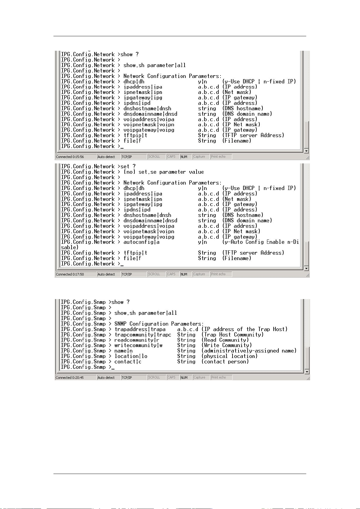
CLI COMMAND MODES
Figure 9-4 Network Mode show and set Commands
79 of 244
Rev H

CLI COMMAND MODES
Figure 9-5 SNMP Mode show and set Commands
Figure 9-6 VLAN Mode show and set Commands
Figure 9-7 H323 Mode show and set Commands
80 of 244
Rev H

CLI COMMAND MODES
Figure 9-8 SIP Mode show and set Commands
81 of 244
Rev H

CLI COMMAND MODES
Figure 9-9 MGCP Mode show and set Commands
Figure 9-10 HTTP Mode show and set Commands
Figure 9-11 Power Mode show and set Commands
82 of 244
Rev H

CONFIGURING THE VOIP GATEWAY VIA THE WEB
11 Configuring the VoIP Gateway
via the Web
You can configure the VoIP Gateway remotely via a PC Web browser. To do so, enter the IP
address of the VoIP Gateway into the Web browser and access the VoIP Gateway (e.g.,
http://172.25.4.26). The VoIP Gateway can be configured to use a fixed IP address or to
acquire an IP address from a DHCP server. T he VoIP Gateway is factory set to acquire an IP
from a DHCP server (use the show command in main CLI mode to see the current IP).
To update a setting, enter the requi red settings on a web page and then save the changes by
clicking on the Save button at the bottom of the page. Once all settings have been saved,
select the Reset option on the left-hand side of the Web page to reset the VoIP Gateway and
activate the new settings.
11.1 Assigning an IP Address to the VoIP Gatew ay using
Web Configuration
To change the mode from using DHCP to fixed IP, or to assign a different fixed IP
address, configure the unit as follows:
1. If th e VoIP Gateway unit is using DHCP (DHCP is the default setting. In some cases
after setting Fixed IP the address could be 10.1.0.54):
• Connect the VoIP Gateway to a network with a DHCP server.
• Configure a PC with an IP address on the same subnet.
2. Connect your PC to the VoIP Gateway (or via a hub or a switch).
3. Enter the IP address of the VoIP Gateway unit into the PC Web browser.
The
VoIP Gateway Home Page appears (Figure 10-1 shows the Home Page when
running the SIP application).
83 of 244
Rev H

CONFIGURING THE VOIP GATEWAY VIA THE WEB
Figure 10-1 VoIP Ga t eway Home Page
4. In the vertical menu bar on the left, click Network. The Network Status Page appears.
84 of 244
Rev H

CONFIGURING THE VOIP GATEWAY VIA THE WEB
on the horizontal menu bar. The
Figure 10-2 Network Status Page
5. To change network settings, select Network Update
Network Update page appears (Figure 10-3).
85 of 244
Rev H

CONFIGURING THE VOIP GATEWAY VIA THE WEB
Figure 10-3 Network Update Page
6. Select either of the following options.
To use a fixed IP address:
• Select fixed LAN Configuration
• Fill in or change the fields associated with fixed IP addressing:
IP Address, IP Netmask, IP Gateway, IP DNS Server, Host Name, Domain
Name
Or
To use a DHCP server:
• Select Use DHCP to obtain LAN configuration
86 of 244
Rev H

CONFIGURING THE VOIP GATEWAY VIA THE WEB
7. Scroll down to the bottom of the Web page, and click the Save Settings button.
8. Select Reset in the vertical menu bar to reset the unit (see Completing the VoIP Gateway
Configuration on page 129).
You can now use the new IP address.
11.1.1 Setting the VoIP Gateway to be a DHCP Client
To use a DHCP server to supply an IP address to the VoIP Gateway, you must first configure
the unit appropriately by selecting the Use DHCP to obtain LAN configuration option, as
described in step 6 above.
We recommend that you configure your DHCP server to assign the same address to the VoIP
Gateway unit each time it is powered up. This will help to track the available V oIP Gateway
units during the VoIP Gateway and Gatekeeper configuration.
When the VoIP Gateway unit is powered up, it queries the DHCP server for an IP address.
You must know this “new” IP address, assigned by the server, in order to access the VoIP
Gateway Web Setup Facility. To determine which IP address refers to your VoIP Gateway,
see the IP address in the CLI opening screen that appears when the unit boots with a t erminal
(see
Upgrading the Gateway Firmware and Downloading Configuration Files on page 51).
11.1.2 Using VoIP Gateway with a Fixed Address
If you do not have access to a DHCP server, and your Gateway is configured to use a DHCP
server, or if you do not know the IP address used by the Gateway, configure your Gateway
via a terminal connected to the AUX/Consol e por t (not avaible for 232 products, use Keypad
Configuration). You can also view the IP address or disable DHCP.
11.2 VoIP Pr ot oc ol Conf iguration
Once the VoIP Gateway unit has obtained its IP address, you can use the Web Configuration
to configure the VoIP Gateway. To be able to place calls, you must configure the VoIP
protocol parameters, appropriate to the VoIP protocol installed in the VoIP Gate way (H.323,
MGCP or SIP). Refer to sections which detail H.323 configuration, MGCP configuration, or
SIP configuration.
11.3 Autoconfiguration
To enable and set automatic configuration (see Upgrading the Gateway Firmware and
Downloading Configuration Files on page 51):
1. In the horizontal menu bar of the Network page, select AutoConfguration. The
Automatic Configuration page appears (
Figure 10-4).
87 of 244
Rev H

CONFIGURING THE VOIP GATEWAY VIA THE WEB
check box for enabling automatic
. The Gateway will run the configuration file
For DHCP Download you can set the ID also at the DHCP server along with the file
The ID at the DHCP server or in the Configuration file can be set to the literal value
ry boot without
In DHCP download (Bootp), the Gateway must be in DHCP mode. The name of the
“root” configuration file and the IP of the TFTP server are supplied to the Gateway
Figure 10-4 Automatic Configuration Page
2. Select the Enable Automatic Configuration
configuration.
Note: If more information on Automatic Configuration i s needed than provided here,
refer to the Auto Configuration Download Guide.
3.
Enter the Automatic configuration ID
only if the file name or ID is different from the ones currently stored in the Gateway.
name (e.g., ipg_12345.cfg, 8). For Fixed Auto Configuration, the ID can also be se t in
the “root” Configuration file.
“always”, causing the configuration file to be executed on eve
comparing to the ID stored in the Gateway.
4.
when the Gateway queries the DHCP server for an IP address and a boot file, during
boot and at half lease-time.
To enable using DHCP options 66, 67, select the Use DHCP code options 66,67
check box. When this check box is selected:
Option 66 (Boot Server Host Name) is set as the IP of the TFTP server for the “root”
configuration file.
Option 67 (Bootfile Name) is set as the name of the “root” configuration file.
88 of 244
Rev H

CONFIGURING THE VOIP GATEWAY VIA THE WEB
y the IP address of the
and the name of the “root” configuration file directly to the
Gateway, instead of through the DHCP options. During boot, and at defined polling
5. For Fixed Auto Configuration, set the polling interval in hours.
6.
To select Fixed (Provisioned) Auto Configuration, suppl
HTTP/TFTP server
periods, the Gateway will poll the HTTP/TFTP Server for a configuration file an d wi ll
determine if an upgrade is needed.
7. Set the Server IP address.
8. Set the file name (“root” configuration file) to download.
9. Set the Server protocol (HTTP or TFTP).
11.4 VLAN Configuration
To set VLAN configuration on the VoIP Gateway unit:
In the vertical menu bar of the current VoIP Gateway Web page, select VLAN.
1.
The VLAN Configuration page appears (Figure 10-5
).
NOTE
The 282/482 product supports 8 LAN p orts and up to sixteen VLANS.
The 483S/483D products supports 8 LAN ports, one/two fiber optic
ports and up to sixteen VLANS. The 232 produc t supports four LAN
ports and up to eight VLANs.
2. Proceed as described in the following subsections.
89 of 244
Rev H

CONFIGURING THE VOIP GATEWAY VIA THE WEB
Figure 10-5 VLAN Configuration Page
11.4.1 Using VLANs on the VoIP Gateway
VLANs (Virtual LANs) logically group a set of stations to communicate as if they were on
the same LAN segment. Traffic between VLANs is restricted. Unicast and broadcast traffic is
forwarded only to LAN segments of the same VLAN. The VoIP Gateway enables you to
configure up to sixteen 802.1Q-compatible VLANs on the 282/482/483S/483D model and up
to 8 VLANs on the 232 nodel. A VLAN is identified by a unique number from 1 to 4095
(VLAN ID). By default, the VLAN configuration is disabled and traffic is free to travel
between all VoIP Gateway ports.
90 of 244
Rev H

CONFIGURING THE VOIP GATEWAY VIA THE WEB
In the column under the number of each port that is permitted to be a member of the new
11.4.2 VLAN Tagging on the VoIP Gateway
VLAN tagging is required to identify traffic from more t han one VLAN on the same port. A
“tag” is simply the VLAN identification number (VLAN ID), as specified in the 802.1Q
standard. The tag is included in the packets forwarded across the LAN. You can allow the
VoIP Gateway to connect to non 802.1Q-compliant devices by adding/removing the tag from
packets according to tag def in it ion s in the VL A N con f ig u rat io n table.
11.4.3 VLAN Configuration Proce dure on the VoIP Gateway
Use the TAB key or click to move around the table in the VLAN configuration page . The
VoIP Gateway is factory set with VLAN ID – 1 assigned by default to all the ports of the unit.
Each port must have a default ID. All packets received on the VoIP Gateway ports without a
VLAN tag will inherit the default VLAN ID of the receiving port as their VLAN ID.
You can use the VLAN configuration page to define new VLANs.
To define a new VLAN, proceed as follows:
1. In the VLAN column, enter the new VLAN ID.
NOTE For EdgeGate 282/282S/482S/483S/483D when IGMP is enabled, the Gateway
uses VLAN IDs in the range 1792-1842 internally. Therefore, VLAN IDs in this
range should not be used by the user.
2. In the Ports table, in the row corresponding to the new VLAN ID:
VLAN (see figure below):
• Enter T if packets of the VLAN are to be transmitted from the port with a VLAN
tag in the packet (Tagged).
• Enter U if packets of the VLAN are to be transmitted from the port without a
VLAN tag in the packet (Untagged).
Note: The 232 product supports four LAN ports and up to eight VLANs.
91 of 244
Rev H

CONFIGURING THE VOIP GATEWAY VIA THE WEB
Once the port members of a VLAN have been entered, you can assign the VLAN as the
default VLAN for any port. If it is, assign another VLAN as default for the port(s) and
3. You can use the Del key to remove a port, if it is not a member of the new VLAN.
4.
default VLAN for one or more ports that belong to that VLAN. Select the proper VLAN
ID on the default VLAN row in all the required ports.
5. If you wish to remove a VLAN from the VLAN column, first make sure it is not a
then delete the original VLAN.
Once the VLAN configuration table is set and VLAN Enable is selected, packets received at
an VoIP Gateway port will be forwarded only to ports of the same VLAN (ports that have
their port member field set to “T” or “U” for that VLAN).
Traffic addressed to the VoIP Gateway unit (Web management or VoIP protocol frames) will
be received and transmitted on any of the defined VLANs.
92 of 244
Rev H

CONFIGURING THE VOIP GATEWAY VIA THE WEB
11.5 Voice and Management Services Configuration
To further refine the VLAN configuration and assign a VLAN per protocol, for frames where
the VoIP Gateway is the source or the destination, use the Voice and Management Services
Configuration screen. The user can assign VLAN and priority tags to outgoing frames. This
will help devices such as switches and routers in the LAN to serve the frames with higher
priority queues and with lower delays. Service VLANs can be defined also for security
reasons. With service VLANs for IGMP, the VoIP Gateway can support multi-IGMP queries
and multicast streams.
To configure the Voice and Service management:
In the vertical menu bar of the current VoIP Gateway Web page, select Services. The Voice
and Management Services Configuration Page appears (Figure 10-6
).
Figure 10-6 Voice and Management Services Configuration Page
93 of 244
Rev H

CONFIGURING THE VOIP GATEWAY VIA THE WEB
in order to activate IGMP, VLANs must be enabled and an
The following fields are available in this window.
NOTE VLAN tags are simply VLAN IDs. Priority tags are simply priority values.
Management/ All
VLAN Tag
To assign a unique VLAN tag to all management including ping and
voice, enter a VLAN value in the range 1-4095.
Priority Tag
VLAN Tag for RTP
packets
Priority Tag for RTP
packets
TOS for RTP
packets
VLAN Tag for Call
Signalling packets
Priority Tag for Call
Signalling packets
TOS for Call
Signalling packets
IGMP VLAN Tag list
To assign a priority tag to all management including ping and voice,
enter a value in the range 0 (lowest priority) to 7 (highest priority).
To assign a unique VLAN tag to the outgoing RTP frames, enter a
VLAN value in the range 1 – 4095. Overrides the VLAN Tag field.
To assign a priority tag to the outgoing RTP frames, enter a value in
the range 0 (lowest priority) to 7 (highest priority). Overrides the
Priority Tag field.
To assign a priority using the TOS field in the IP header of the RTP
frames, insert a TOS value in the range 0-255. The default value is
184.
To assign a unique VLAN tag to the start frames of the VoIP call
session, enter a VLAN value in the range 1 – 4095. Overrides the
VLAN Tag field.
To assign a priority tag to the start frames of the VoIP call session,
enter a value in the range 0 (lowest priority) to 7 (highest priority).
Overrides the Priority Tag field.
To assign a priority using the TOS field in the IP header of the VoIP
call session frames, insert a TOS value in the range 0-255. The
default value is 104.
To assign a list of unique VLAN tags to IGMP protocol and IP
Multicast frames, enter up to eight VLAN values in the range 1 –
4095.
IGMP Priority Tag
Excluded
Management VLAN
Tag
To assign a priority tag to IGMP protocol and IP Multicast frames,
enter a value in the range 0 (lowest priority) to 7 (highest priority).
Select this option to use the Service VLAN option that supports
flooding of IP multicasts within the VLAN without the need for IGMP
reports. It is possible to set up to 16 excluded VLANs .
NOTE If a service VLAN is defined, the VLAN must be a valid VLAN for the incoming
port. To define a VLAN on the incoming port, see
89.
page
VLAN Configuration on
11.6 IGMP Conf iguration
NOTE
By default, IGMP is enabled.
For 232 products,
IGMP service must be set.
94 of 244
Rev H

CONFIGURING THE VOIP GATEWAY VIA THE WEB
The VoIP Gateway supports IGMP Snooping. This feature reduces the unnecessary use of
bandwidth by IP multicast traffic in LAN TV and other applications. If an IGMP querier
exists on the LAN, the VoIP Gateway can listen to the reports from the IGMP hosts to the
multicast router/querier and discover which multicast group hosts are connected to the VoIP
Gateway ports. It then maps the connections between multicast router/querier and multicast
group hosts. This enables the Gateway to direct multicast group traffic directly to the ports of
the hosts belonging to the multicast group, thereby eliminating traffic that has no mapped
destination.
NOTE For EdgeGate 282/282S/482S/483S/483D products, when IGMP is enabled, the
Gateway uses VLAN IDs in the range 1792-1842 internally. Therefore, VLAN
IDs in this range should not be used by the user.
To enable control of the multicast traffic with IG MP:
In the vertical menu bar of the current VoIP Gateway Web page, select IGMP. The IGMP
Configuration page appears (
Figure 10-7).
Figure 10-7 IGMP Configuration Page.
The following options and entries are available in this window:
IGMP Enable Select this option to enable IGMP. By default the Gateway is set to
this mode. For 232 products an IGMP service must be defined
95 of 244
Rev H

CONFIGURING THE VOIP GATEWAY VIA THE WEB
Immediate Leave
Proxy IP
Minimum Query
Interval
Last Member Query
Interval
Last Member Query
Count
Select this option if, on each port of the VoIP Gateway, only one
host sends IGMP multicast groups reports (the host can be a
member of multiple multicast groups and a specific group can be on
a few ports).
This option enables the VoIP Gateway to use a simple and faster
Leave algorithm.
Optional IP address used in IGMP when the unit sends IGMPspecific queries. If you want the regular IP address to be used,
leave this field blank.
General queries received within an interval less than the Minimum
Query Interval are not transferred to the IGMP hosts and their
report status is not updated. Response although is transmitted to
the IGMP querier based on reports for the last valid query. The
default value for the Minimum Query Interval is 5 seconds and the
range is 5-2000 seconds.
This value, in units of 100 msec, specifies the Maximum Response
Time inserted into Group-Specific Queries which the VoIP Gateway
sends in response to Leave Group messages received on the VoIP
Gateway ports. You may enter values in the range 5-100 (0.5-10
seconds). The default value is 10 (one second). A smaller value
allows less time to detect the leave of the last member of a
multicast group. See Note
The number of group-specific queries sent before the unit assumes
that there are no local members. The default value is 2, and the
allowed range is 1-9. The number is effective only if Immediate
Leave is not selected.
below.
Enable IP Multicast
Flooding
Min IP address
Max IP address
This field defines how the VoIP Gateway treats IP multicast frames
that were not requested by any host.
If IP Multicast Flooding is disabled, then any IP multicast frame
within the range specified by Min IP address and Max IP address
will be filtered if no host reports that it belongs to its multicast group.
If Multicast Flooding is enabled, then an IP multicast frame without
any host report is flooded to all host ports.
These fields specify the filtering range of unrequested frames if IP
Multicast Flooding is disabled.
NOTE
The VoIP Gateway assumes that the Last Member Query Interval used by the
Querier is the same as the Last Member Query interval configured in the VoIP
Gateway. Using a larger interval by the Querier could cause a short period of
flooding of group multicasts.
11.7 SNMP Conf iguration
To enable access of the VoIP Gateway from a Network Management Station, you must
configure SNMP parameters.
To view and update the SNMP configuration:
In the left-hand menu of the current VoIP Gateway Web page, select SNMP (Figure 10-8).
The SNMP Configuration page appears. Make selections
96 of 244
Rev H

CONFIGURING THE VOIP GATEWAY VIA THE WEB
Figure 10-8 SNMP Configuration Page
The following fields are available in this window:
SNMP Trap Configuration:
IP address
Trap Community
SNMP Community Configuration:
Read Community
Write Community
SNMP System Info:
Contact Person
Administratively Assigned Name
Physical Location
For further details on SNMP features, refer to SNMP Management Overview on page 157.
97 of 244
Rev H


CONFIGURING THE VOIP GATEWAY VIA THE WEB
12 Configuring Security via the
Web
In today’s networks, security is very important for protecting the Gateway and your local
network from hackers. The f oll owi ng s ecur ity features are available in the Gateway using the
Web management interface:
• Password - to prevent access to the Gateway’s configuration.
• Advanced security - specifying a list of IP addresses that can manage the Gateway (up to
eight IP addresses can be set in the IP address list).
• DHCP security – to receive an IP address and other configuration parameters only from a
DHCP server that is listed in the IP address list (up to eight IP addresses can be set in the
IP address list).
• Blocking the Gateway management via HTTP and/or Telnet on the LAN interfaces.
• Support for User Mode (limited Web access). Option available only for 232 products.
• Installing an Encryption Key in order to use encryption with a configuration file.
12.1 Defaul t S ecurity Configuration
Table 11-1 Default Security Configuration
Parameter Default Value
Password None
Advanced security Disabled
DHCP security Disabled
HTTP access on the LAN interfaces Enabled
Telnet access on the LAN interfaces Enabled
12.2 Setting the Password
You can use a security password to prevent access of configuration of the V oIP Gateway unit
by unauthorized users via the Console or the Web Configuration pages.
To set an Administrator password:
1. In the vertical menu bar of the current VoIP Gateway Web page, select Security.
The Set Security Administrator Password page appears (
Figure 11-1).
99 of 244
Rev H

CONFIGURING THE VOIP GATEWAY VIA THE WEB
Figure 11-1 Set Security Admininistrator Password Page
2. Enter the new password and confirm it.
3. Click Save Password to effect the change.
You can use Advanced Security to select secured IP and/or port.
12.3 Configur ing Advanced Security
You can use Advanced Security to select secured IP and/or port.
To configure Advanced Security:
1. In the horizontal menu bar of the Set Security Password page, select Advanced. The
Advanced Security Configuration page appears (
Figure 11-2).
100 of 244
Rev H
 Loading...