

Page 1

FiberLeap
TM
Installation and
Operation Manual
Access Unit Model AU2006
Telaxis
Telaxis Communications Corp.
20 Industrial Drive East
S. Deerfield, MA 01373-0109 USA
413-665-8551
www.tlxs.com
PN 50315 745 REV. ED1
P/N 50315 745 REV. ED1
Page 2

Table of Contents
Section Contents Page
FCC, Safety and Service Information.................................................................................... 2
FCC Licensing and Compliance
Safety Information
Service Precautions
1 Overview............................................................................................................................. 3
Application
Hardware Description
About This Manual
2 Unpacking and Inspection ................................................................................................... 5
Parts Identification
3 Getting Started ................................................................................................................... 5
Tools Required
4 Installation .......................................................................................................................... 7
1. Attach Mount Assembly to Mast ................................................................................. 7
2. Attach FiberLeap Access Unit to Mount/Mast .............................................................. 10
3. Make Cable Connections to FiberLeap Access Unit ...................................................... 12
4. Power-Up FiberLeap .................................................................................................... 13
5. Make Final LOS Adjustment to FiberLeap Access Unit .................................................. 14
6. Test the Link ................................................................................................................15
5 Operation ........................................................................................................................... 16
6 Inspection and Maintenance ............................................................................................... 16
7 Appendices ......................................................................................................................... 17
Installation Record .......................................................................................................... 17
Telaxis
P/N 50315 745 REV. ED1
1
Page 3

FCC, Safety and Service
Information
FCC Licensing
FiberLeap operates as an unlicensed device under FCC Rules, Part 15, Low Power
Communication Device Transmitter.
FCC Part 15 Rules Compliance
This Device complies with Part 15 of the FCC Rules. Operation is subject to the
following conditions:
• This device may not cause harmful interference
• This device must accept any interference received, including interference that
may cause undesired operation.
The FiberLeap Access unit has no user accessible controls and may not be
modified or altered in any way. Changes or modifications to the equipment could
void the user’s warranty.
FCC RF Exposure Compliance
The Federal Communications Commission (FCC), with its action in General Docket
93-62, November 7, 1997, has adopted a safety standard for human exposure to
Radio Frequency (RF) electromagnetic energy emitted by FCC regulated equipment. Telaxis subscribes to the same safety standard for the use of its products.
Proper operation of this equipment will result in user exposure far below the Occupational Safety and Health Act (OSHA) and Federal Communications Commission
limits.
FCC ID# P57-AU2006
Safety Notice
This unit has been tested for RF emission levels and found not to exceed the FCC
RF exposure requirements for occupational and general public exposure. Even
though the RF levels external to the unit are not hazardous to humans, Telaxis
believes it is prudent to minimize all exposure to RF emissions and therefore
recommends the installation be such that the RF beam emitted by the antenna
be positioned over the heads of any personnel working in the vicinity.
WARNING DO NOT position FiberLeap Access Unit LOS (Line of Site) in
such a manner that the antenna beam is directed towards areas
where maintenance personnel might be working while the unit
is operating.
Service Precautions
Failure to follow these installation instructions could damage the equipment
and/or improper operation may result.
• FiberLeap is designed and sold for installation and maintenance by trained,
qualified professionals.
• For service, the unit must be returned to Telaxis CUSTOMER ASSISTANCE
CENTER.
Telaxis
P/N 50315 745 REV. ED1
2
Page 4
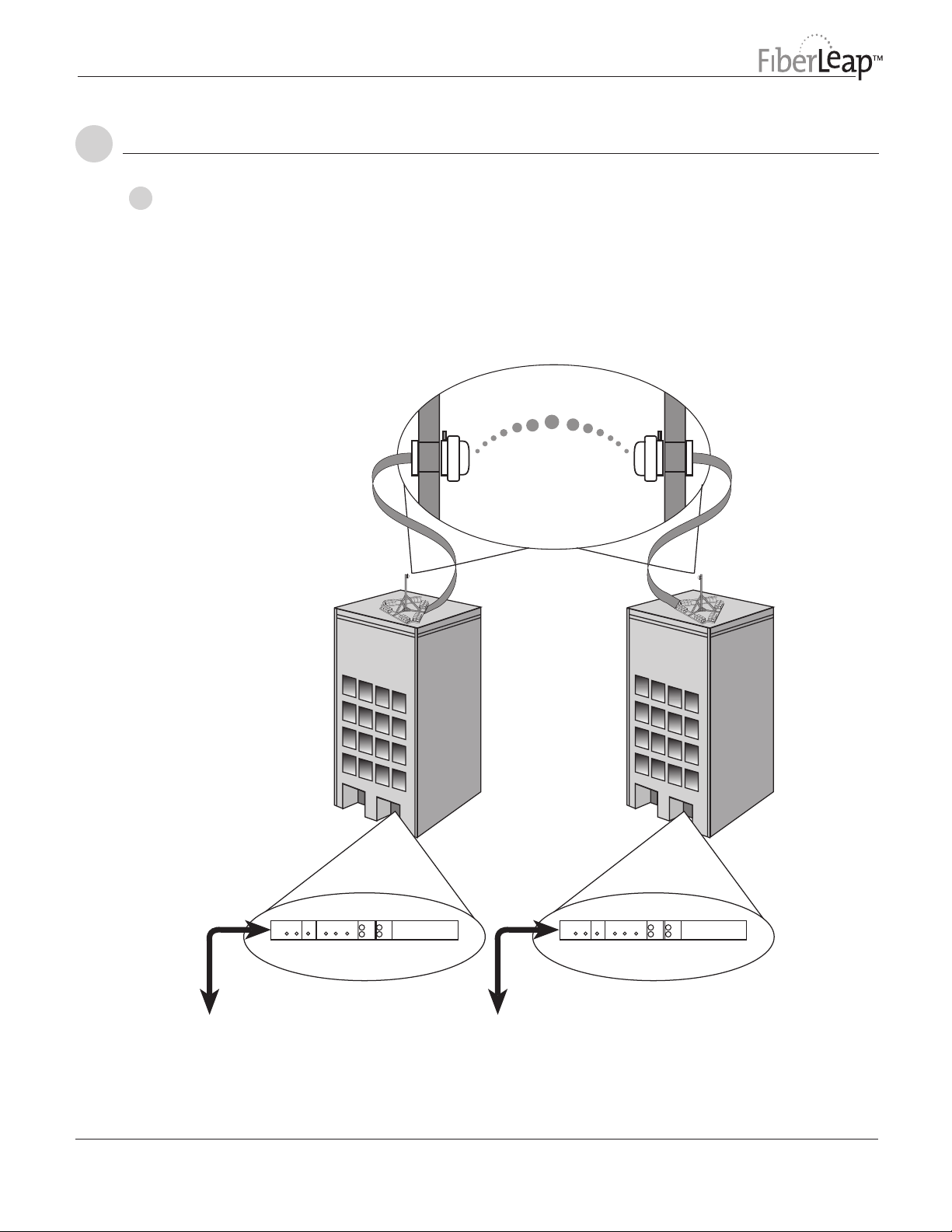
Overview
Access
Unit A
Access
Unit B
1
Application
Figure 1
FiberLeap Link
Overview
Serviced by Fiber
System Cable System Cable
“On Net”
Building
The FiberLeap™ product is designed to extend the reach of fiber optic networks
through wireless connections where installation barriers and high cost make
installing additional fiber connections less desirable. Telaxis has developed this
product to enable direct fiber optic connection and transmission of fiber optic
signals over a wireless link without the use of conventional modems. These fiber
extension links function, and can be managed and serviced, as if they were a
length of fiber optic cable.
“Off Net”
Building Not
Serviced by Fiber
Telaxis
Fiber Optic Data
to-from Network ADM
ACCESS UNIT 1
LOS
LOSFAILPWR
Interface Panel
ACCESS UNIT 2
ACCESS UNIT 1
ACCESS UNIT 2
TX
TX
LOSFAILPWR
RX
RX
OC DATA
OC DATA
Fiber Optic Data
to-from Building MUX
P/N 50315 745 REV. ED1
ACCESS UNIT 1
LOS
LOSFAILPWR
Interface Panel
ACCESS UNIT 2
ACCESS UNIT 1
ACCESS UNIT 2
TX
TX
LOSFAILPWR
RX
RX
OC DATA
OC DATA
3
Page 5

Hardware
Description
About this
Manual
A FiberLeap fiber extension link consists of:
• FiberLeap Access units (2) with Mast Mounting Assembly Kit
• FiberLeap Interface Panels (2)
• FiberLeap System Cables (2)
The two Access Units are mounted within direct visual LOS (Line-of-Site) of each
other. Each of the two Access Units is connected to an Interface Panel (located
indoors), by means of a System Cable. The Interface Panels connect to the fiber
optic network (see Figure 1).
This Installation and Operation Manual provides instructions on how to install
the Access Unit on one end of the Link, which is then repeated for the second
end of the link. This installation procedure assumes that the necessary
rooftop mast for mounting the Access Unit, the System Cable and the
FiberLeap Interface Panel have already been installed.
Telaxis
P/N 50315 745 REV. ED1
4
Page 6

Inspection and Unpacking
2
Inspect the shipment packaging and contents for any obvious damage due to
shipment. If any damage is evident, you should immediately file a claim with the
transporter.
The Packing List itemizes each component shipped. Verify each part and the
indicated quantity. If any parts are missing, immediately contact:
FiberLeap Customer Assistance Center (CAC)
www.fiberleap.com
1-413-665-8551 x350
email: [email protected]
Parts
Identification
Getting Started
3
FiberLeap Access Unit
1 ..... FiberLeap Access Unit, Model AU2006
1 ..... FiberLeap Installation and Operation Manual (AU2006)
3 ..... Flat Hd Bolt, M10 x 35
1 ..... 5 mm Allen Key
1 ..... Locktite
Mast Mounting Assembly Kit
1 ..... Mount Kit
4 ..... Hex Nut, M10
4 ..... Lockwasher, M10
4 ..... Washer, Flat, M10
1 ..... Mast Mount Installation Instructions
Before initiating the actual installation of the Access Unit, certain other activties
should already have been accomplished. These include:
1. A Site Enginering Study – This study would have been initiated by a site survey
to determine all the physical and environmental constraints of the installation.
The engineering study ensures that the performance of the data link can be
met and specifies the details of the installation, i.e. the location of the Interface Panel, the mount/mast for the Access Unit and its location, identification
of the power source, length of the System Cable, length of the wireless link,
far end Access Unit location, etc.
2. Installation of the Rooftop Mast for the Access Unit – A suitable mast, 2.5
to 4.0” O.D., of sufficient height to meet the Access Unit mounting height
requirement specified in the engineering study must have been installed. This
mast must be braced or ballasted to survive high winds and grounded to the
rooftop lightning protection system in accordance with NEC or local regulations.
3. Installation of the System Cable – This installation must have been completed
in conformance with building requirements and governing codes by trained
and licensed installers.
TM
Thread Locking Compound
Telaxis
P/N 50315 745 REV. ED1
5
Page 7

Getting Started (cont.)
4. Installation of the Interface Panel – The Interface Panel should be either rack or
wall mounted in a suitable location in the Equipment Room to allow easy
connection to the ADM and the dc power source.
5. Review of Installation Details – The installer should review the engineering
study to assure an understanding of all the installation requirements. This
includes the Access Unit type ( A or B), mounting height, LOS (Line-Of-Site)
direction to the far end of the link, antenna polarization (Horizontal or
Vertical) and ADM data source identification.
Tools Required
Hardware Installation, Cable Connections and LOS Alignment
• Open end wrench, 17mm
• 5mm Allen key (supplied with Access Unit)
• Crimping Tool (Ground lug attachment to ground wire)
• Multimeter for dc voltage measurement and continuity checks.
• BNC-to-test lead adapter
• BER Tester or other OC-3/OC-12 SONET data source/analyzer
Telaxis
P/N 50315 745 REV. ED1
6
Page 8
Installation
4
Attach Mount
1
Assembly to Mast
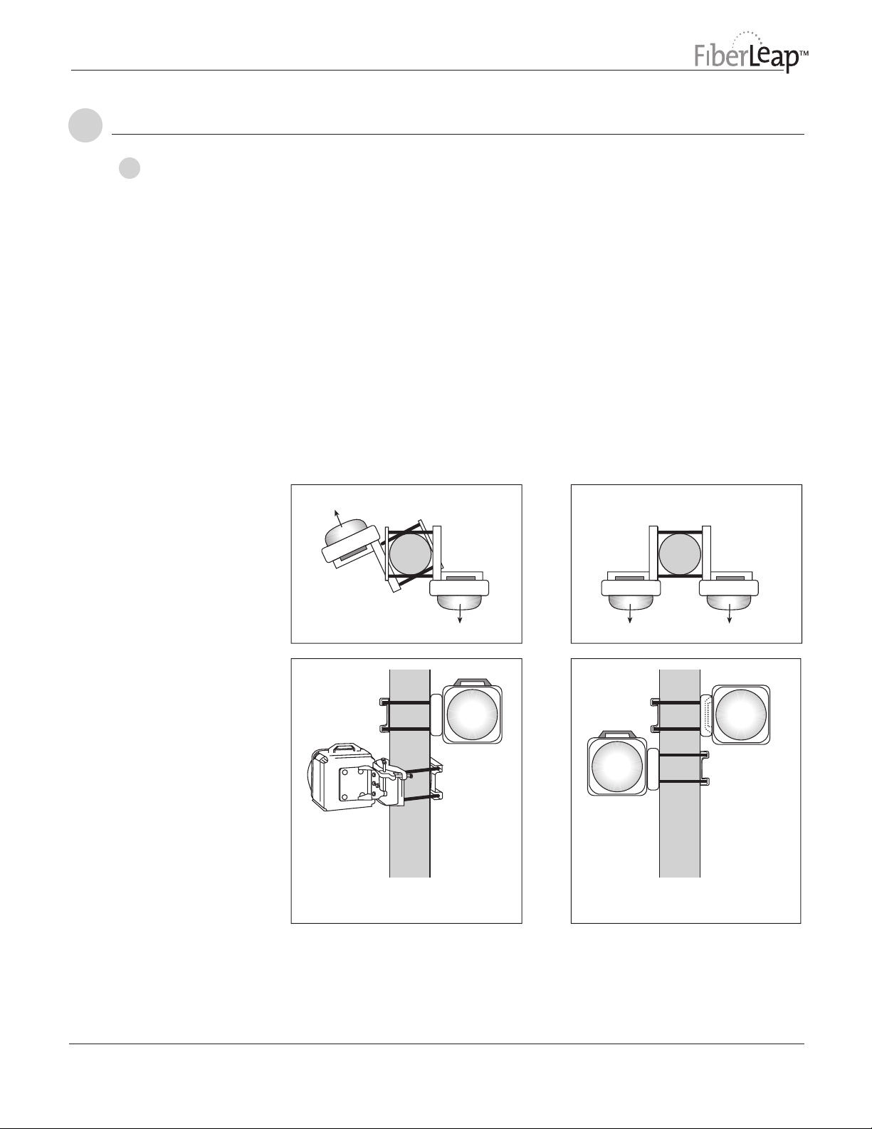
Figure 2
Multiple Access Units
with Different and
Same LOS
The site engineering study specifies the physical requirements for mounting the
Access Unit and the installer must refer to that document to determine the predetermined parameters for properly installing the Mount Assembly and Access Unit:
• height above the roof deck
• direction of the LOS (visual sight line link far end)
• Access Unit type at each link end (A or B)
• Access Unit polarization (handle orientation)
Note: An installation involving two Access Units (links) on the same mast and
pointing in different directions usually requires both Access Units positioned for
horizontal polarization (Access Unit handles oriented horizontally). An installation involving two Access Units (links) on the same mast and pointing the same
direction, i.e. at the same link far end, requires one Access Unit positioned for
horizontal polarization (Access Unit handle oriented horizontaly) and the second
Access Unit positioned for vertical polarization (Access Unit handle oriented
vertically). See Figure 2.
Two Access Units with
Different LOS
LOS
Top View
Two Access Units with
Same LOS
Top View
Side View
LOS
LOS
Horizontally
Polarized
(note handle
orientation)
Side View
LOS
Vertically
Polarized
(note handle
orientation)
Telaxis
P/N 50315 745 REV. ED1
7
Page 9
Attach Mount
1
Assembly to
Mast (cont.)
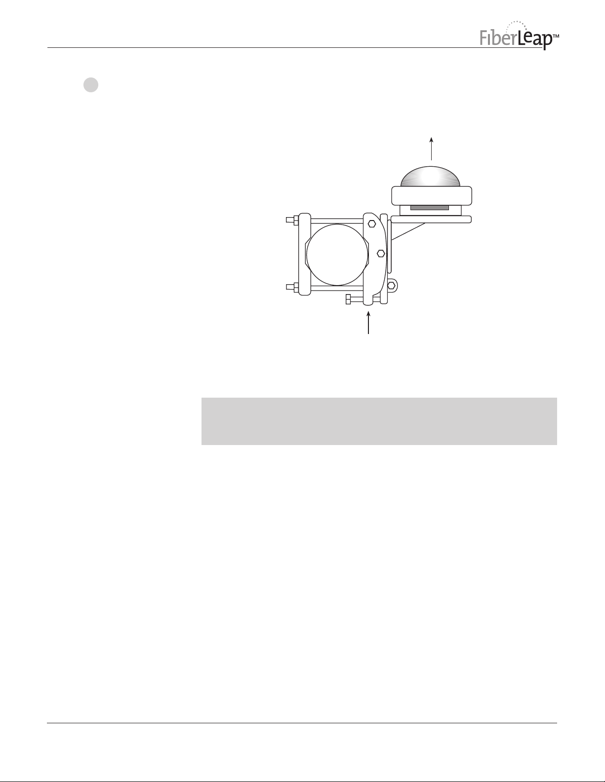
Figure 3
Mount Assembly
for Orientation LOS
• The Mount Assembly is mounted on the same side of the mast intended for
the Access Unit. (Figure 3).
LOS
Top View
Mast
Mount Assembly
CAUTION: When working on a roof or on a ladder, mast or staging,
use extreme care. Observe all facility and OSHA (or other applicable
regulatory agency) required safety precautions.
Telaxis
P/N 50315 745 REV. ED1
8
Page 10
Attach Mount
1
Assembly to
Mast (cont.)
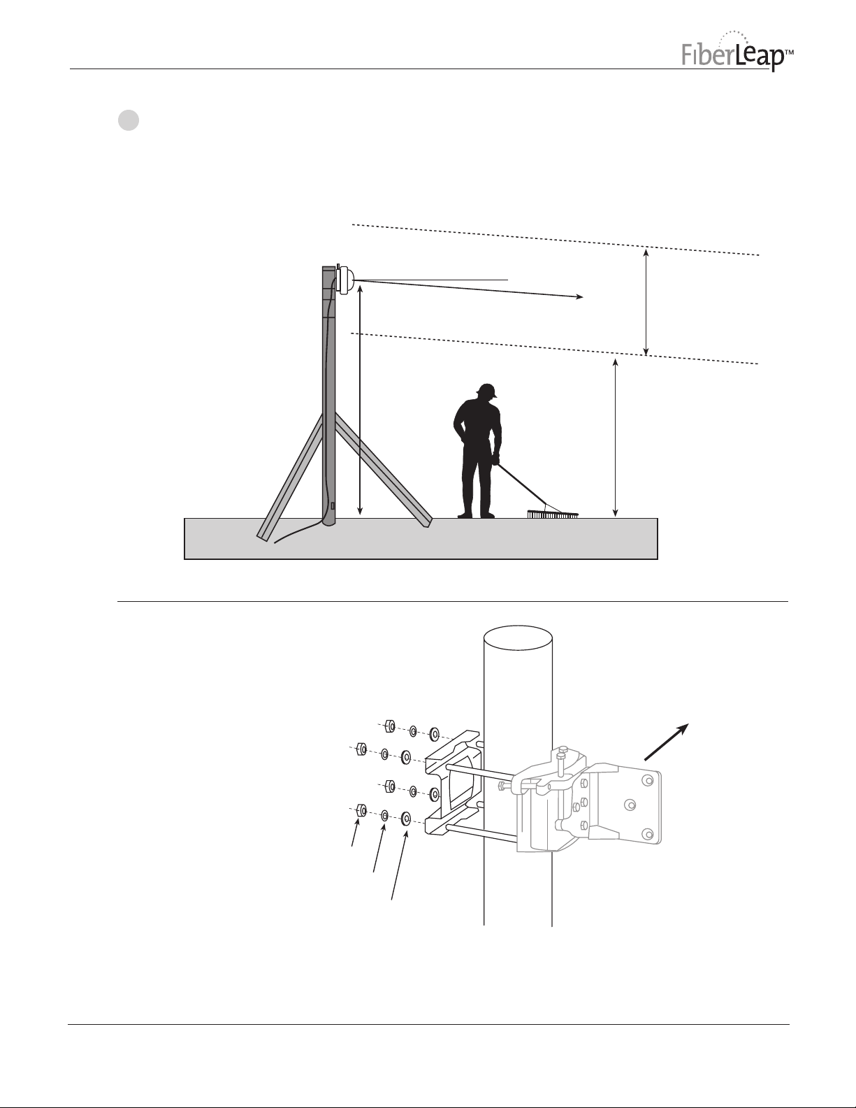
Figure 4
Mount/Access Unit
Height Above Roof
Install the Mount Assembly on the mast, at the height specified in the site
engineering analysis (Figure 4).
Use the 4 Hex Nuts, 4 Lock Washers and 4 Flat Washers to secure the Mount
Assembly to the Mast as shown below (Figure 5).
Mast
Plumbed
Horizontal
LOS
h = Access Unit Height
LOS Corridor ~2m
Corridor must be clear
from obstruction (wiring,
chimneys, etc.)
2 Meters Minimum for
Personnel Safety
~
Telaxis
Figure 5
FiberLeap Mounting
Hardware
Hex Nut
Lock Washer
Flat Washer
Torque mast mounting
nuts to 22Nm (16.2 lb-ft)
P/N 50315 745 REV. ED1
LOS
9
Page 11
Attach FiberLeap
2
Access Unit to
Mount/Mast
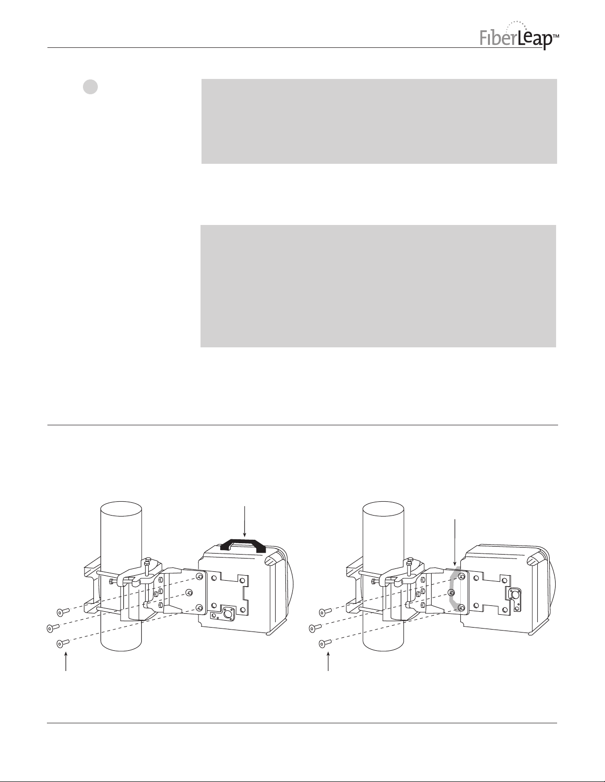
CAUTION: Handle Access Unit carefully to prevent damage.
• Carry the unit by the handle provided
• Avoid impact or shock to the unit, especially to the antenna radome
• When handling/moving the unit, always have protective caps on
conectors (2)
1. Position the Access Unit to the Mount, orienting the Access Unit for Horizontal
(handle horizontal) or Vertical polarization (or handle vertical), as specified in
the System Engineering Analysis.
IMPORTANT:
• Polarization of the near end and far end Access Units must be the
same. The System Engineering Analysis designates Horizontal or Veritcal
polarization.
• Each link is comprised of two Access Units, one type A and one type B,
as designated by the last digit of its model number (example AU2006-A
is type A). Install the type A and type B Access Units in the near end or
far end, as specified in the System Engineering Analysis.
Figure 6
Access Unit and Mast Mounting
2. Attach using 3 M10 x 35 Flat Head bolts thru the 3 holes provided in the
Mount. Apply Locktite
to torque bolts to 22 N-m (16.2 lb-ft).
Horizontal Polarization
(handle horizontal)
TM
to threads of bolts. Use the 5mm Allen key provided
Vertical Polarization
(handle vertical,
parallel to mast)
Apply Locktite to threads Apply Locktite to threads
Telaxis
P/N 50315 745 REV. ED1
10
Page 12
Attach FiberLeap
2
Access Unit to
Mount/Mast
(cont.)
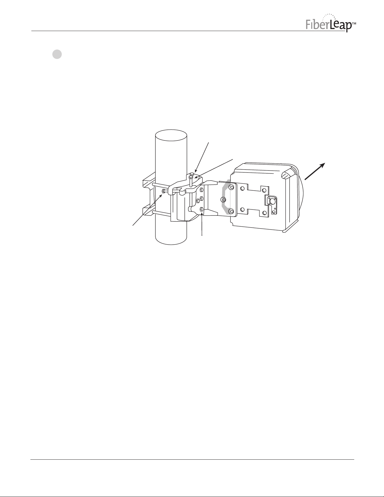
Figure 7
Adjustment of
Azimuth and
Elevation
3. Sighting along the edge of the Access Unit toward the far end of the link,
adjust the Azimuth and Elevation Adjustment Screws so the near end Access
Unit LOS points at the far end Access Unit.
Slacken (2) bolts (top and bottom)
1/2 turn to adjust Azimuth
LOS
Azimuth
Adjustment
Screw
Elevation Adjustment Screw
Slacken (4) bolts 1/2 turn
to adjust Elevation
Line of Sight
Telaxis
P/N 50315 745 REV. ED1
11
Page 13
Make Cable
3
Connection to
FiberLeap
Access Unit
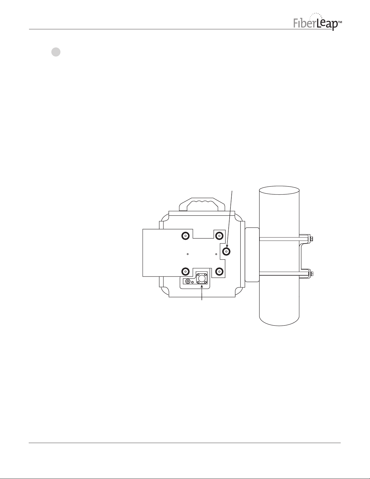
Figure 8
FiberLeap Access
Unit Back View with
Sun Shield
1. Ensure that the Access Unit power switch on the Interface Panel (rear) is OFF.
2. Route an AWG 6 ground wire and System Cable up the mast and dress
appropriately approximately every 18”using cable ties such that the wiring is
close to the mast and an adequate service loop remains to connect to the
Access Unit.
3. Crimp 1 M10 x (.39 inch I.D.) Ring Terminal on the AWG 6 ground wire using
the appropriate crimping tool and setting.
4. Attach the ground wire to the Access Unit using the M10 x 10mm Hex Hd
Bolt, M10 Lock Washer and M10 Flat Washer thru the Ring Terminal. Torque
to 22 N-m (16.2 lb-ft).
5. Remove the protective caps on the Access Unit main connector and the
System cable connector and connect the System cable to the Access Unit.
6. Mate the two protective caps.
Ground Wire
Connection
Telaxis
System Cable
Connection
P/N 50315 745 REV. ED1
12
Page 14
Power-Up
4
FiberLeap
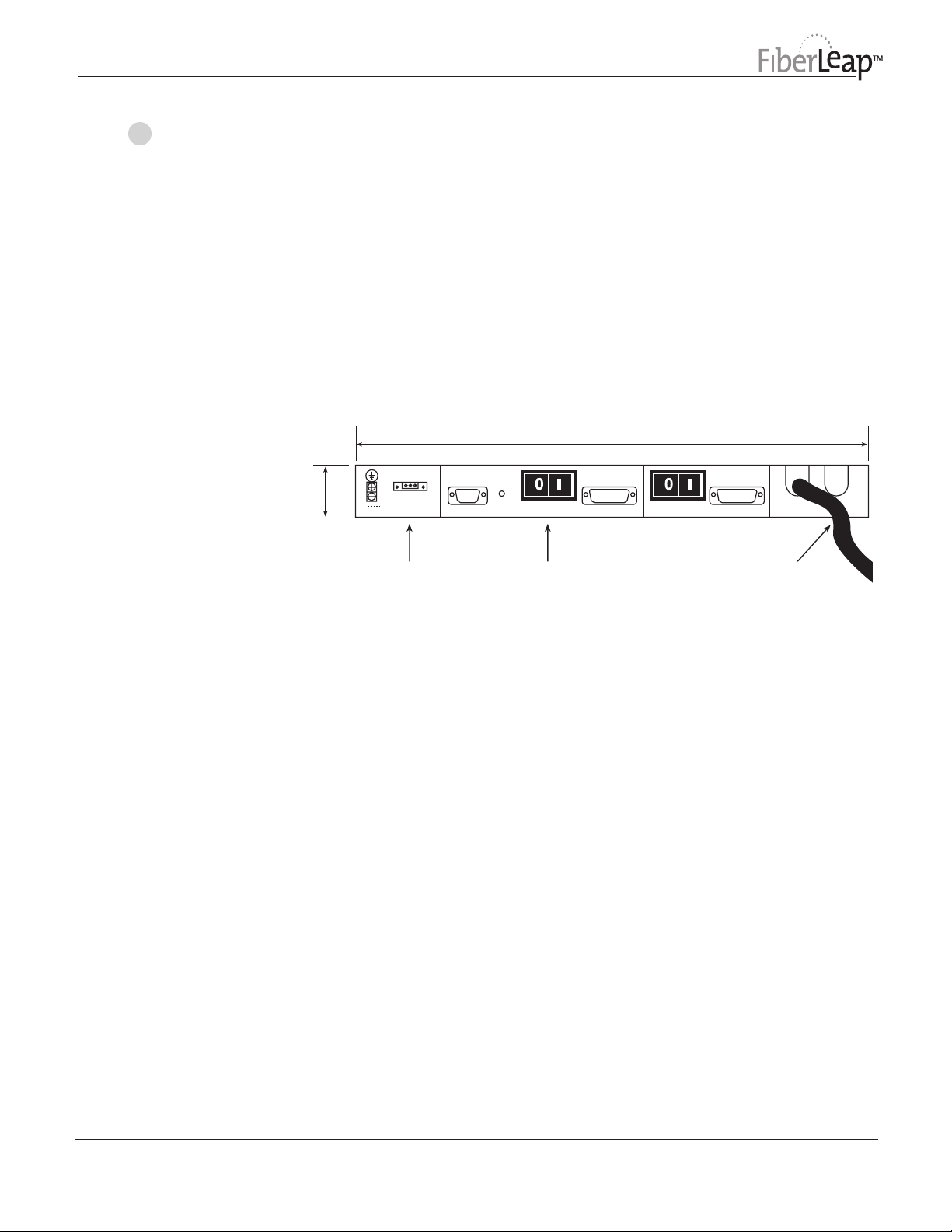
Figure 9
Interface Panel
Connections
1. Verify that the System Cable is connected to the Interface Panel.
2. Verify the connection of the Interface Panel to the power source. Observe
proper polarity of the dc power connections (red = +, black = -).
3. Enable the power source to the Interface Panel.
4. Verify the power source voltage is between 36-60 Vdc using a voltmeter at
the dc input power terminals on the Interface Panel.
5. Turn ON Access Unit power at the Interface Panel. Green LED should
illuminate to indicate power is available and enabled. The Yellow and Red
LEDs should initially be OFF, but may illuminate after 10-60 seconds.
Back View
16.50
DC INPUT
1.72
POWER
(+) NC (-)
+/- 36 - 60 VDC, 2.8A
RS 232
RESET
ACCESS UNIT 1
ALARMS
ACCESS UNIT 2
ALARMS
UNIT 1 UNIT 2
ACCESS UNIT INTERFACE CABLE
DC Power
Connection
Power Switch
Access Unit 1
Interface Cable
Telaxis
P/N 50315 745 REV. ED1
13
Page 15
Make Final LOS
5
Adjustment to
FiberLeap
Access Unit
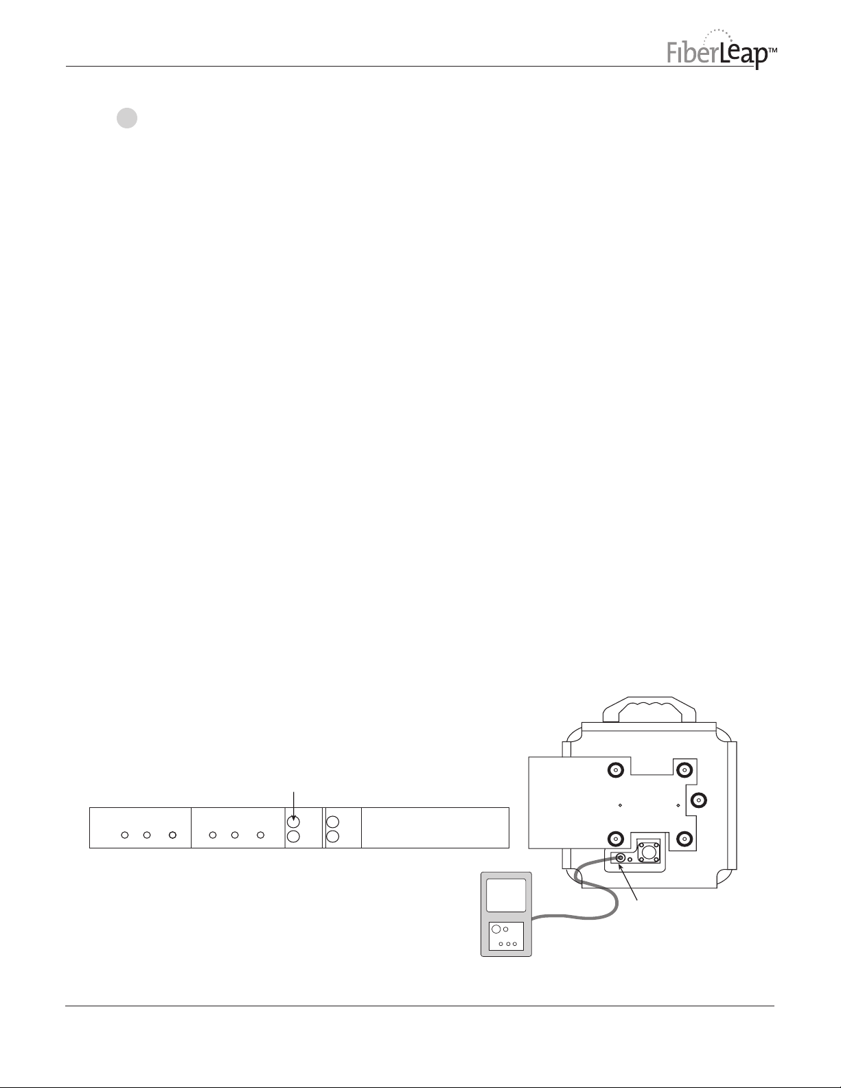
The purpose of this step is to adjust the LOS (Line of Sight) of the Access Unit to
maximize the signal level. During this step, the second FiberLeap Access Unit at
the far end of the link must also be installed and powered ON. A continuous TX
data signal must also be present at the far end link. For purposes of Final LOS
alignment and signal optimization, a BERT (Bit Error Rate Tester) or an ADM with
BERT capability may be used to feed a SONET test pattern into the OC DATA, TX
input connector of the FiberLeap Interface Panel at the far end. Refer to Figure 7
unless otherwise noted.
1. Connect a dc voltmeter to the BNC connector on the rear of the Access
Unit using a BNC-to-test lead adapter. The voltmeter should read a dc voltage
of between 0.5 to 5.0 volts (see Figure 10).
2. Slacken the 2 azimuth clamp bolts on the Mount 1/2 turn. Using the
Azimuth Adjustment Bolt, adjust the azimuth LOS until the reading on the
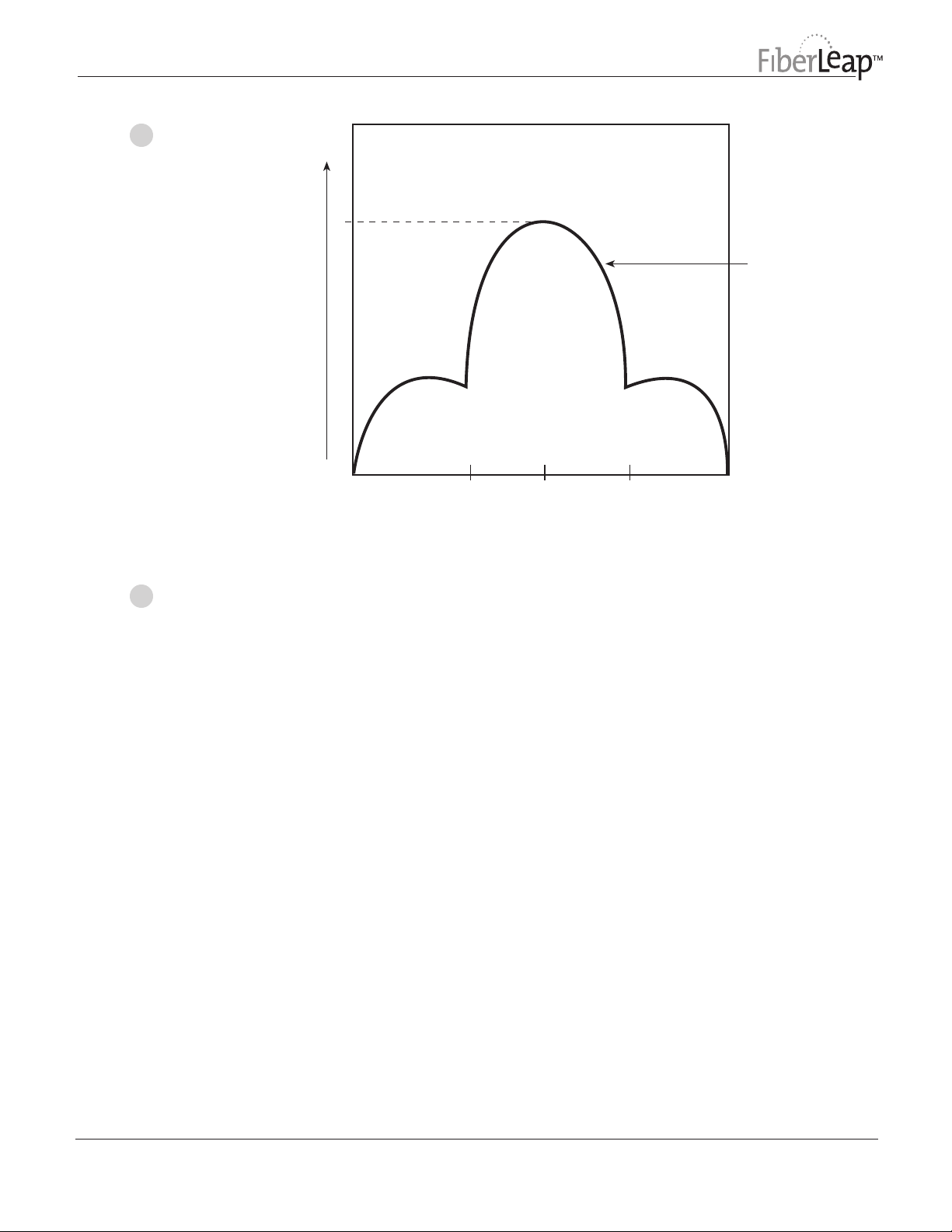
voltmeter is at a maximum. It is advised that, in order to ensure the true
maximum, you should adjust through the maximum (peak voltage) until
the voltage clearly begins to drop and then adjust back until the maximum is
attained again (see Figure 11).
3. Tighten the 2 Azimuth clamp bolts on the Mount while observing the
voltmeter reading to ensure the azimuth alignment does not change while
tightening. Tighten bolts to 22 N-m (16.2 lb-ft).
4. Slacken the 4 Elevation clamp bolts on the Mount 1/2 turn. Using the
Elevation Adjustment Bolt, adjust the elevation LOS until the reading on
the voltmeter is at a maximum. It is advised that, in order to ensure the true
maximum, you should adjust through the maximum until the voltage clearly
begins to drop and then adjust back until the maximum is attained again.
5. Tighten the 4 Elevation clamp bolts on the Mount while observing the
voltmeter reading to ensure the elevation alignment does not change. Tighten
Nuts to 22 N-m (16.2 lb-ft).
6. Repeat steps 1 through 5 (above) to guarantee optimum alignment for
maximum signal strength.
Figure 10
Final LOS Adjustment and Signal Optimization
for Link #1 (Access Unit 1 on A and B ends of Link)
Far End
Interface Panel
ACCESS UNIT 1
LOSFAILPWR
LOS
Feed a BERT Tester
SONET test pattern
ACCESS UNIT 2
LOSFAILPWR
ACCESS UNIT 1
TX
RX
OC DATA
ACCESS UNIT 2
TX
RX
OC DATA
0.5 to 5.0
Volts
Near End
Access Unit #1
Connect DC Voltmeter
Should read 0.5 to 5.0 Volts
Telaxis
Voltmeter
P/N 50315 745 REV. ED1
14
Page 16
Make Final LOS
5
Adjustment to
FiberLeap
Access Unit
(cont.)
Figure 11
Peak Signal
BNC
Connector
Volts
Note: It is possible to obtain a false peak signal
on a side lobe. Be sure to obtain voltage
readings over a wide angle.
peak
side lobe side lobe
0
AZ, EL Position (degrees)
2-2
Antenna gain pattern
and voltmeter output
are similar.
Test the Link6
Prior to placing link in service for network traffic, the link should be tested for
BER using standard procedures for fiber optic cables.
The Installation Record (see page 17) and Warranty Registration should be
completed with pertinent installation information.
Telaxis
P/N 50315 745 REV. ED1
15
Page 17

Operation
5
Operation of a FiberLeap link is quite simple. There are no user controls or
adjustments possible except for the ON/OFF switches on the Interface Panels at
each end of the link, and aiming the LOS (alignment) of the Access Units. Once
turned ON, the units are fully operational.
If SONET data is being supplied by the network to the OC TX connector at the
Interface Panel, the Access Unit will transmit that data to the link far end Access
Unit. Absence of a valid SONET signal will mute the transmitter.
In the event of network alarms, refer to the FiberLeap Troubleshooting Guide.
Please note that any attempt to open or modify a FiberLeap Access Unit will void
the warranty.
Inspection and Maintenance
6
Routine Inspection of the FiberLeap Access Unit and exterior portions of the
Cables should be performed at least once per year to check for loose hardware,
damage, corrosion or other disturbance to the installed hardware. Any damage,
corrosion or conditions not conforming to the original installation should be
corrected immediately.
Replacement of an Access Unit, Interface Panel or Cable, or any realignment of
either of the two FiberLeap Access Units requires a retest for BER (see pages 14-15).
Telaxis
P/N 50315 745 REV. ED1
16
Page 18
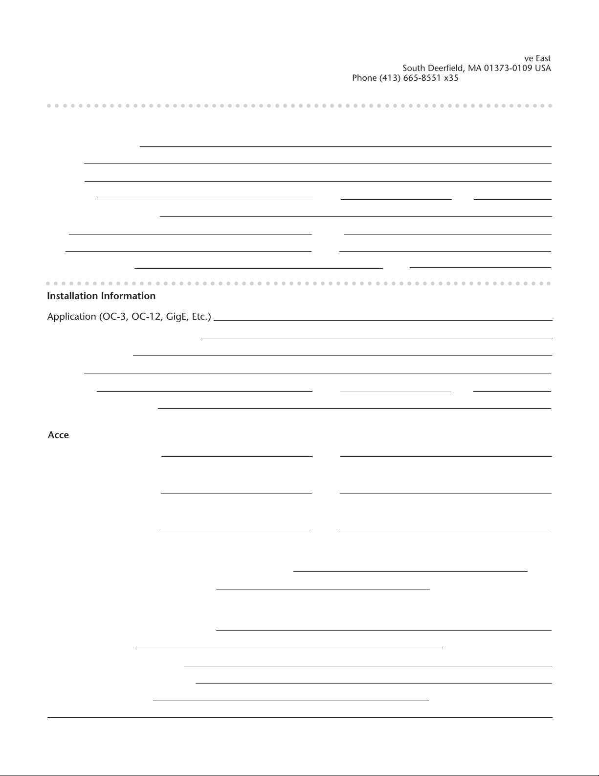
FiberLeap
Installation Record and Warranty Registration
Please completely fill out and return a copy of this form to
Telaxis (mail, fax, or email at the addresses listed on the right).
○○○○○○○○○○○○○○○○○○○○○○○○○○○○○○○○○○○○○○○○○○○○○○○○○○○○○○○○○○○○○○○○○
TM
South Deerfield, MA 01373-0109 USA
Phone (413) 665-8551 x350 • Fax (413) 665-7090
Email: [email protected]
Telaxis Communications
Customer Assistance Center
20 Industrial Drive East
Purchasing/Leasing Company Information
Customer/Company
Address
Address
City/Town
State
Zip
Company Contact Name
Title
Phone
Fax Email
Purchase Order No. Date
○○○○○○○○○○○○○○○○○○○○○○○○○○○○○○○○○○○○○○○○○○○○○○○○○○○○○○○○○○○○○○○○○
Installation Information
Application (OC-3, OC-12, GigE, Etc.)
Company Link Indentifier Number
Installation Address
Address
City/Town
State
Zip
Installer Name/Company
Access Unit
Model Number
State
Interface Panel
Model Number State
System Cable
Model Number State
Installation Parameters
LOS Alignment Voltmeter Reading, Maximum
Link Distance, Approximate
BER Test
Technician Company/Name
Test Date
Payload/Test Pattern
Bit Error Rate Achieved
Test Duration
Telaxis
P/N 50315 745 REV. ED1
Volts
Meters Feet (circle one)
Pass Fail (circle one)
Days Hours (circle one)
17
 Loading...