

Tela TGM133, TGM134 Instruction Manual
TELA merilni sistemi
Scale Unit TGM133/134
Instruction Manual
ID 430 261 710 000, 4th Edition
Safety Precautions
TELAms products are designed in full consideration of safety. However,
improper handling during operation or installation is dangerous and may
lead to fire, electric shock or other accidents, resulting in serious injury or
death. In addition, these actions may also worsen machine performance.
Therefore be sure to read this Manual before operating, installing,
maintaining, inspecting, repairing or otherwise working on this unit.
Warning, Caution
• Do not use this unit with voltages other than specified supply
voltage as this may result in fire or electric shock.
• Do not disassemble or modify the unit as this may result in injury or
damage the internal circuits.
• Be sure to check the machine and device conditions to ensure safety
work on a machine.
• Be sure to switch off the power supply, air and other sources of
drive power before working on the machine.
• When turning on a machine power supply, take care about moving
parts of a machine and corresponding devices.
General precautions
When using TELAms products, observe the following general precautions along
with those given specifically in this manual to ensure proper use of the products.
• Provide adequate safety measures to prevent damages in case the product
should develop malfunctions.
• Use outside indicated specifications or purposes and modification of our
products will void any warranty of functions and performances
• When using our products in combination with other equipment, the functions
and performances as noted in this manual may not be attained, depending on
operating and environmental conditions.
TGM133/134 Instruction Manual May 2013 4th Edition 2/24

Installation precautions
When installing this unit, care should be given to the following points to
prevent noise and electromagnetic wave interference from other equipment.
1. Do not pass lead and connection cables through the same ducts as
power lines.
2. Be sure to install the unit at least 0.5 m or more away from high voltage
or large current sources or high-power relays.
Installation place precautions
1. Mount the scale as closely as possible to the work-piece or to the object
being measured. Further the scale is mounted, greater is measuring error.
2. The scale unit should be used within an ambient temperature range of 0
to 50°C. Avoid locations where the scale is exposed to direct sunlight and
heat sources such as motors.
3. Do not place anything on the mounted scale, or step on it: excessive
force to the scale causes trouble.
Before installation
Do not disassemble parts other than scanning unit holder. All electrical
adjustments have also been completed before shipment. So do not tamper any
additional adjustment at time of its installation.
This scale unit consists of precision mechanism parts and electromagnetic
parts. Therefore, applying excessive pressure to the unit can seriously harm
the performance and service life of the scale. Be careful not to apply
excessive pressure to the scale unit when proceeding with the work.
When the unit is to be carried, support the scale unit and reading head
altogether. Do not hold the unit by the head cable, connectors, etc.
Ensure that the scale unit housing and reading head as well as the circuit
breaker for the supply power are properly grounded.
Standard procedure for EMC compliance.
When equipment such as controller does not function properly due to the effects
of large noise from power line please provide ground lines at one point
intensively. Power source which has a remote sensing function, must be used for
TGM133. Power unit without remote sensing unit may fail to prove optimum
functions. Please provide proper power source by referring to Section 5.
TGM133/134 Instruction Manual May 2013 4th Edition 3/24

Table of contest
5
5
5
6
2. Specifications………………………………………
………….
7
3. Name and Function of Part
s ……
…………………
……….
8
4. Mounting ………………………………………………
……….
9
4.1. Mounting Precautions……………………………………
…………………………….
9
4.1.1.
Checking the Mounting P
osture………………
……………………………………
9
4.1.2.
Setting the Operation R
ange…………………………
..……………………………
9
4.1.3.
Protection of the Head C
able…………………………..
……………………………
10
4.1.4.
Mounting the Protective C
over……………………...
...
……………………………
10
4.2.
Tools required for Scale I
nstallation……………………
……………………………
11
4.3. M
ount
ing procedure
…………………………………………
………………………
…. 12
4.3
.1.
Mounting the Main U
nit
…………………………………
……………………………
12
4.3
.2. Mounting the Scanning Unit
………………………....
……………………………
13
4.3
.3. Removing the Scanning Unit Holder…………………
……………………………
14
4.3
.4. Checking the Operation Range
………………………
……………………………
15
4.3
.5. Attaching the Head Cable
…………………………….
……………………………
16
4.3
.6. Air Injection
……………………………………………….
…………………………
16
5. Connecting to
a Device ……………………………
……….
18
5.1. Output Signal……………………………………………….
……………………………
18
5.2. Output connector
s
………………………………
…….
…
………
……………………
19
5.3. Alarm ( DS version optionally )………………………….
……………………………
21
6. Dimensions …………………………………………
…………
22
7. T
rouble prevention ………………………………….……….
24
1. Outline …………………………………………………….…...
1.1. Before Operation…………………………………………...…………………………….
1.2. List of Parts Supplied with the Scale Unit……………..……………………………
1.3. Model Configuration……………………………………….……………………………
TGM133/134 Instruction Manual May 2013 4th Edition 4/24
1. Outline
1-1. Before Operation
TGM133/134 series is small, light and high-accuracy optical feedback scale.
This series provides Line driver (A, A-, B, B-, RI, RI- digital output) or
Sinusoidal signals (1Vpp or 11µA output).
Output signals are adjusted before shipment, ex.-factory, each signal can be
readily used for connection to control device as it is.
1-2. List of standard parts supplied with scale unit
TGM133 Scale unit
Parts supplied with scale unit
HSB M8 x 20 2 (For mounting channel)
HSB M4 x 20 2 (For mounting scanning unit)
Cable clamp (small) 3 (For cable clamp)
+P M4 x 10 3 (For cable clamp)
Inspection certificate (Accuracy chart) 1
Instruction manual 1
Air injection valve 1
TGM133/134 Instruction Manual May 2013 4th Edition 5/24
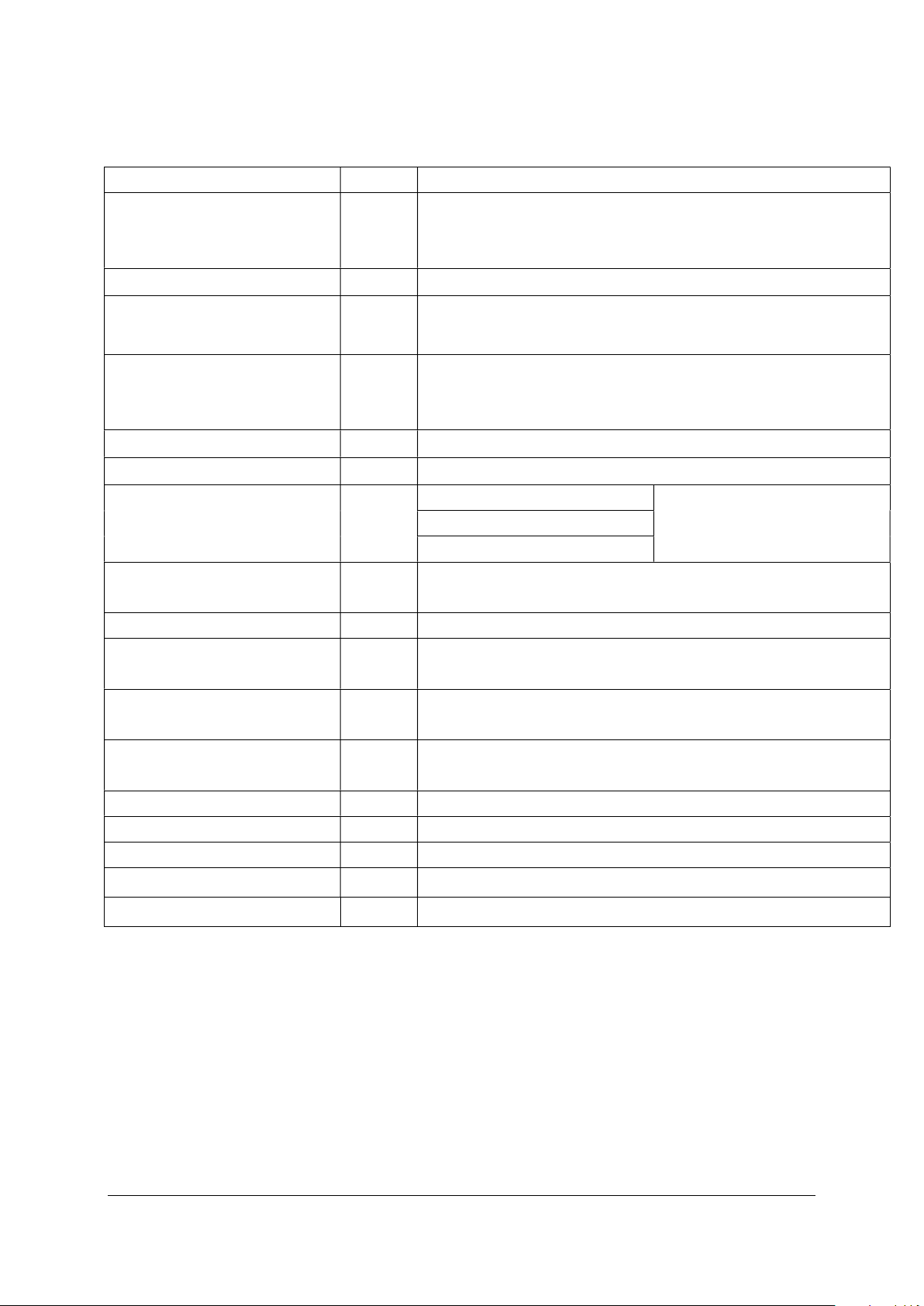
1.3. Model configuration
Standard requirements
XX
1
Voltage supply
05 … 5V
0.1…0.1
m 0.5 … 0.5
m 1 … 1
m
XX
3
Output signals
DS SI SV
0 … without
1 … in the middle
2 … on agreement
4 …
distance coded reference
3 …
3 m 5 …
5 m
length
(see specifications on next page)
Special requirements:
XX
7
Cable length
3m : 03
Example: 1.5m : 1.5, 25m : 25
X8
Connector
*
le
0 … without
1 … with
0 … without
required for Lm
1240mm
TGM133-XX1-X2-XX3-X4-X5-XXXX6-XX7-X8-X9-X
TGM134-XX1-X2-XX3-X4-X5-XXXX6-XX7-X8-X9-X
X2 Resolution
X4 Reference mark
X5 Accuracy
10
10
XXXX
Measuring
6
Standard length [mm]
X9 Metal flexib
tube
X10 Mounting bar
1…with: recommended for Lm 1240 mm,
* Connector is defined with electrical versions SV, DS or SI:
1 … Amphenol 12 pin (DS)
4 … Conntact 12 pin connector (DS, SV)
5 … Conntact 9 pin connector (SI)
6 … Conntact 12 pin coupling (DS, SV)
7 … D-sub 9 pole (DS)
9 … other (specify)
0 … without connector
The difference between TGM133 and TGM134 see in section 6.
TGM133/134 Instruction Manual May 2013 4th Edition 6/24
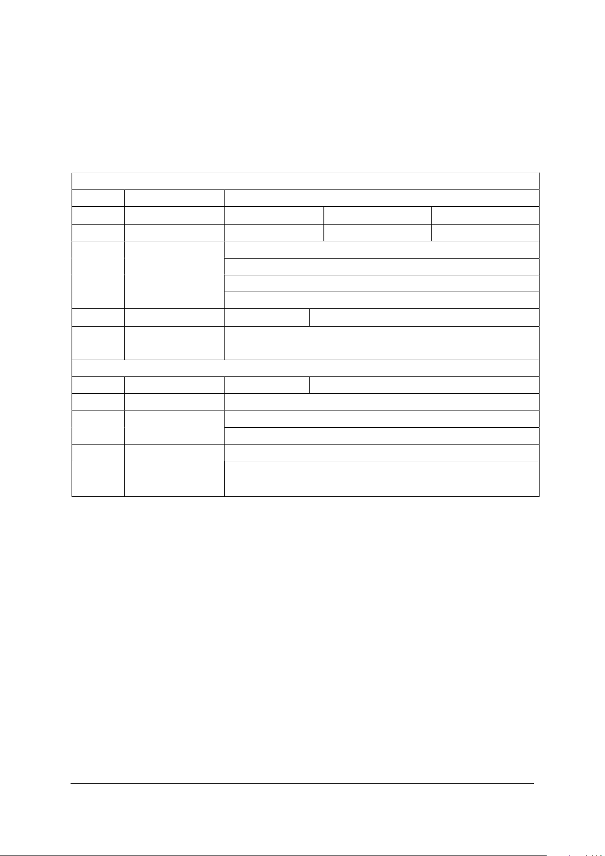
2. Specifications
Items
Unit
TGM133
/134
1340, 1440, 1540, 1640, 1740, 1840, 2040
Scale accuracy (at 20
C)
m
3, 5 (per meter)
Sinusoidal signal: 1Vp
p or 11
A
20 mm apart from each other.) (NOTE 1)
m
m
20 (at 0.1 µm)
50 (at 0.5 µm)
60 (at 1.0 µm)
expansion coefficient
Protection grade
Standard: IP53, with injecting air: IP64
+5 V 1
0
0mA max (SV, SI) (NOT
E 2)
resistance
length
possible) (NOTE 3)
Operating temperature
°C
0 to +50
Storage temperature
°C -30 to +70
Operating humidity
%RH
30 to 90 (No
condensation)
m/s
m/s
Measuring length mm 70, 120, 170, 220, 270, 320, 370, 420, 470, 520, 570,
620, 670, 720, 770, 820, 920, 1020, 1140, 1240,
Output
Reference point Distance Coded Reference (position is reproduced
Resolution
Signal period
Maximum response
speed
Scale temperature
Power supply +5 V 120mA max (DS)
Scanning unit sliding
Maximum capable cable
m/min
K-1
N 3
m
Line driver: A, A-, B, B-, RI, RI-
by passing two adjacent reference marks that are
0.1, 0.5, 1.0 (DS signals)
20
120 (SI, SV)
(8.8 ± 1) X 10-6
Standard 3 (1, 5, 7, 10, 15, 20, 25, 30, 50, 100, 150
Vibration resistance
Shock resistance
(NOTE 1) Any one location can be designated as the reference point, and
multiple reference points (at a pitch of 20 mm) can also be supported.
(NOTE 2) When load resistance of A/B/RI/ALM is 120, refer to section 5-3
for details of power voltage.
(NOTE 3) SV can perform output range of 0.6 V to 1.2 V as A/B phase output
with 150 m cable made by TELAms.
TGM133/134 Instruction Manual May 2013 4th Edition 7/24
2
2
70
300
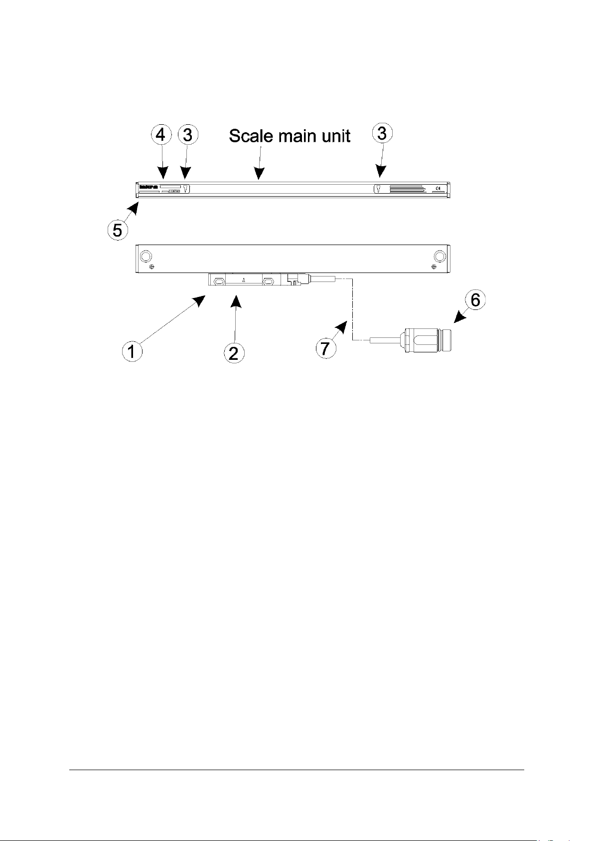
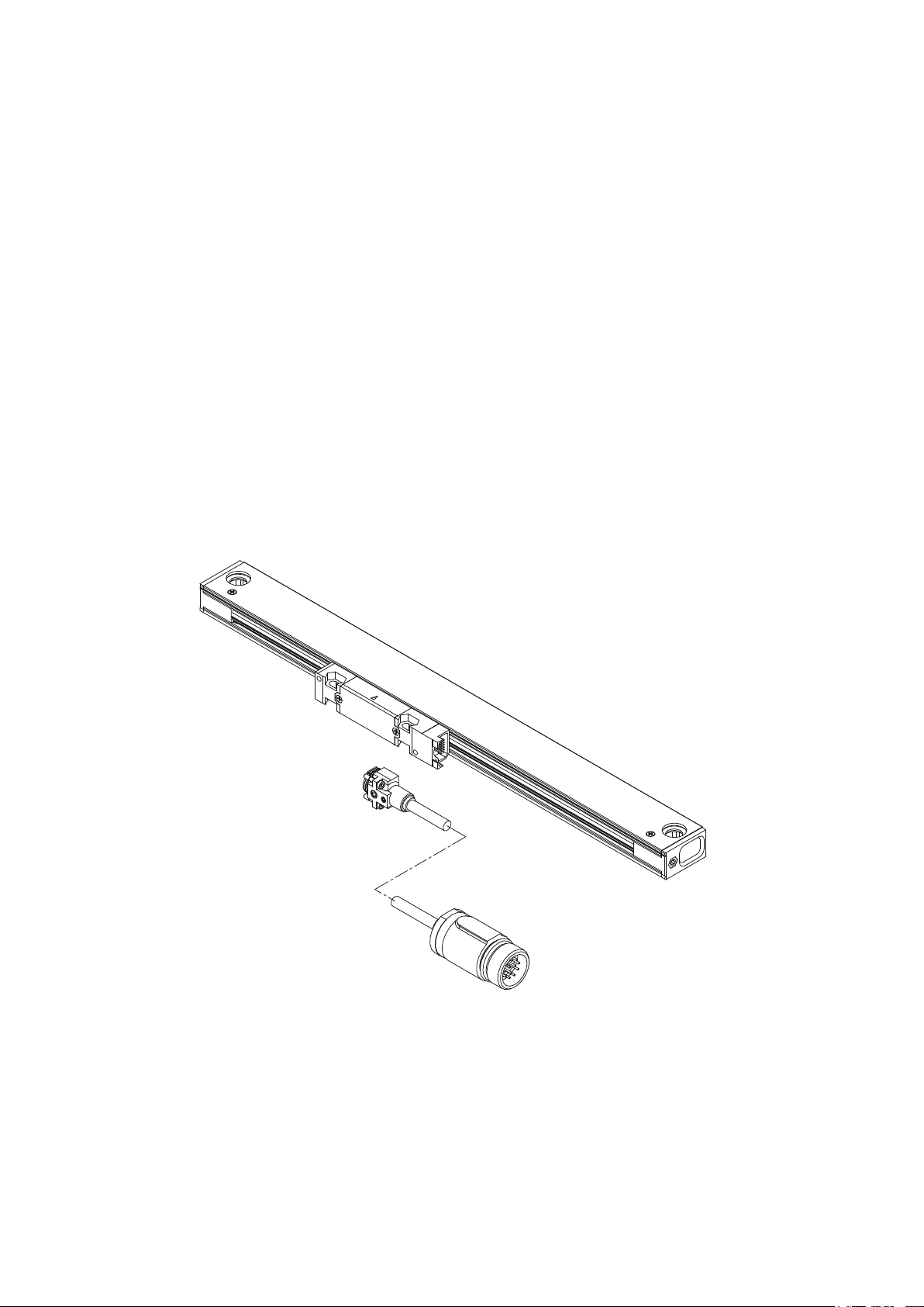
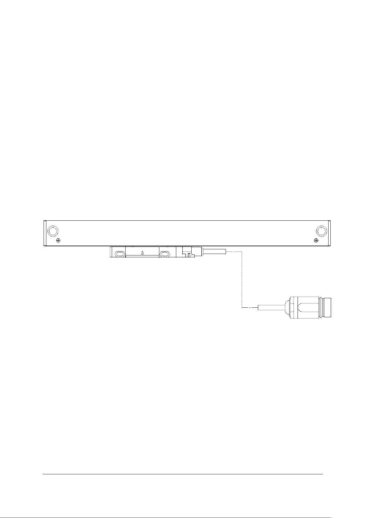
3. Name and Function of Parts
Reading head
This holds the scanning unit. When shipped, it is secured with a scanning unit
holder.
Centre of scanning unit
This indicates the mechanical centre of the scanning unit. It serves as a
reference when viewing the relative position to the measuring length marks.
Measuring length marks
These indicate the effective movement range over which accuracy is assured
with respect to the centre of scanning unit. The measuring length represents
the length of the effective movement range.
Note
When mounting and using the scale unit, be sure to operate the unit within
this range. Using the scale unit in excess of the effective movement range
may damage the unit.
Model name
This indicates the scale unit model name.
Serial No.
This indicates the scale unit serial No.
Connector.
Head cable.
TGM133/134 Instruction Manual May 2013 4th Edition 8/24
 Loading...