


1
AFA 500
FUME HOOD ALARMS
Operating and Instruction Manual
Model AFA 500 – Mk2
• Built-in or Remote sensor
• 2 Relay inputs
• 1 Relay output
• Com port
Used for alarm indication and
monitoring on Fume Hoods
Issue: Jan 08
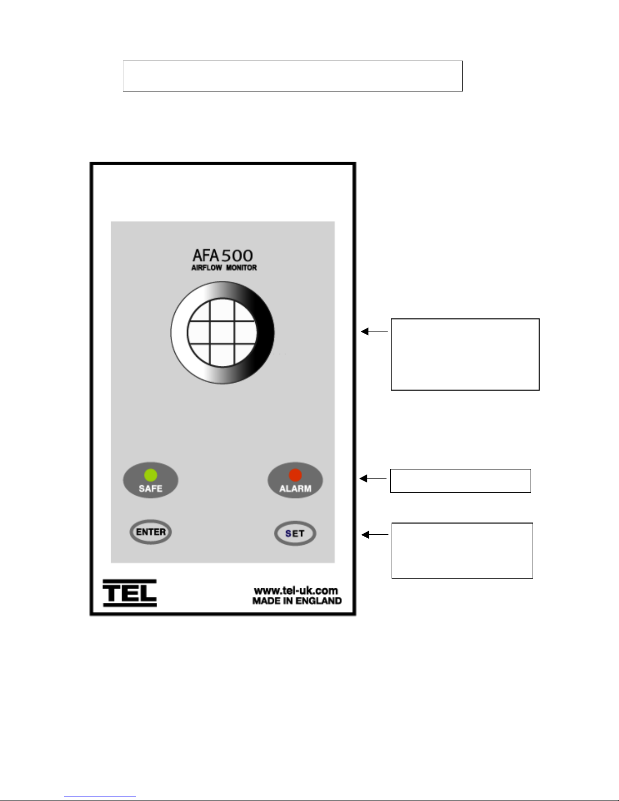
2
LED indicators
Function buttons Calibration.
ENTER – also used as
Mute button for audible alarm
OPERATOR DISPLAY PANEL
Built-in AIRFLOW SENSOR
Not visible when Remote
AIRFLOW SENSOR is used

3
Connection details :-
Com port
RS232
Night set-back
Relay input
Flying lead with plug
connection for PCB
15 V DC
Flying lead with plug
connection for PCB
and SM6 airflow sensor
12V DC
Flying lead from Proxy
switch with plug
connection for PCB
12V DC
Sash High
Proximity switch
( Optional )
Remote
SM6 Airflow Sensor
( Optional )
R1
OPTIONAL
REMOTE
SENSOR
SOCKET
15V DC
POWER
SUPPLY
INPUT
Sash Proximity
switch
OUTPUT RELAY
COMMS
PORT
INPUT 1
Bn
Bk
Bl
Sash
Micro
Switch
REFER TO
INSTALLATIO N
INSTRUCTIO NS
BEFORE
CONNECTING
MADE IN ENGLAND
www.tel-uk.com
WARNING
TEL$
PSU
Relay output 2
Rated 110V
2A AC1
Sash High
Micro-switch
( Optional )
Plug – in power adapter for
mains socket.
(To suit local requirements )
Standard options :-
230V 50Hz -- UK 3-pin
220V 50Hz -- Euro 2-pin
120V 60Hz -- USA 2-pin
AFA 500
Notes:-
1. The socket for the remote SM6 Airflow Sensor is not provided as standard but is available on
request. The unit operates with the in-built sensor OR the remote sensor.
2. The Sash High alarm can operate with the Micro switch OR the Proximity Switch.
Both connection points are available as standard.

4
1.1 General Description
All systems comprise of the following components :-
1 – AFA 500 Alarm unit,
1 – AC power supply
If the Sash Alarm System option is ordered there will also be a sash micro switch or proximity
switch.
If the Remote Airflow Sensor is ordered there will be remote sensor provided
Operator Features --- the alarm has the following operator features :-
Safe LED - Green LED (Not flashing) will be displayed if the airflow is greater than the
Low air alarm point.
Alarm LED - Red LED (Not flashing) will be displayed if the airflow is lower than the
Low air alarm point.
Sash High - Red LED (Flashing) will be displayed when the Sash is raised above
the max safe working opening.
Audible Alarm -- the Audible alarm will sound ( can be muted ) in the Air Fail and the
Sash High alarm condition
Night Set-back -- when the Night Setback input is activated the Audible alarm will be muted
and the Green LED will flash on/off
ENTER --- the alarm has an Enter button -- this is multi-functional as follows :-
Press Enter momentarily when Low Air alarm is sounding will mute the alarm
Press Enter momentarily when Sash High alarm is sounding will mute
the alarm and initiate a repeat timer that will re-sound the alarm if the Sash is
not lowered to a safe position before the end of the time period
Press Enter for 5 secs will gain access to Calibration mode
SET -- used during the airflow Calibration of the alarm

5
External Connections -- the alarm unit will have the following connection points :-
Input 1 --- volt free relay input – ( close contact to activate the input )
This input is configured as :-
NIGHT SETBACK
Output R1 --- volt free relay output - ( contact closes on activation )
This input is configured as :-
LOW AIR ALARM
Sash High Input --- a. Connection point for Sash High micro switch. ( Switch contact to
close and remain closed in Sash High condition )
b. Connection point for Sash High proximity switch. ( Switch contact to
close and remain closed in Sash High condition )
Note:- Use input a. OR input b. for the Sash High alarm
Remote Airflow Sensor -- Plug in connection for airflow sensor
Note:- The remote Airflow Sensor socket will only be available for
units ordered without the built-in Airflow Sensor
Com Port --- to enable connection to Laptop or PC.
Power supply --- low voltage DC power supply 15V DC
 Loading...