

Page 1

TekTouchPad Configuration Utility User’s Guide
Revised: March 12, 2015
Page 2
Contents
INTRODUCTION ..................................................................................................................................................... 4
OPERATIONAL DISCUSSION ................................................................................................................................... 4
THE MAIN WINDOW .............................................................................................................................................. 4
FILE MENU OPTIONS.................................................................................................................................... 5
RESOURCES MENU OPTIONS ....................................................................................................................... 6
OPTIONS MENU OPTIONS ............................................................................................................................ 6
HELP MENU OPTIONS .................................................................................................................................. 6
BUTTON CONTEXT MENU OPTIONS .............................................................................................................. 6
PAGE TITLE ................................................................................................................................................. 6
THE COMMAND EDITOR ........................................................................................................................................ 7
BUTTON ID .................................................................................................................................................. 7
BUTTON LABEL ............................................................................................................................................ 7
TYPE .......................................................................................................................................................... 8
RADIO GROUP ............................................................................................................................................. 8
SCHEME ...................................................................................................................................................... 8
BITMAP ....................................................................................................................................................... 8
CONTROL GROUP ........................................................................................................................................ 8
REPEAT ...................................................................................................................................................... 8
ASCII ......................................................................................................................................................... 9
ADD FEEDBACK ........................................................................................................................................... 9
COMMAND LIST ......................................................................................................................................... 10
Serial Command ............................................................................................................................................................... 10
Delay ................................................................................................................................................................................ 11
Button Press ..................................................................................................................................................................... 11
Lamp Command ............................................................................................................................................................... 11
Goto Page ......................................................................................................................................................................... 12
Output .............................................................................................................................................................................. 12
SYSTEM CONFIGURATION .................................................................................................................................... 13
SPLASH SCREEN ....................................................................................................................................... 13
SPLASH TIMEOUT ...................................................................................................................................... 13
SCREEN TIMEOUT ...................................................................................................................................... 13
PASSCODE ................................................................................................................................................ 14
TEKLINK – FUTURE .................................................................................................................................... 14
INVERT SCREEN ........................................................................................................................................ 14
OPERATIONAL COMMUNICATIONS ............................................................................................................... 14
LOAD COMMUNICATIONS ............................................................................................................................ 14
HOST COM SETTINGS ........................................................................................................................................... 14
CREATING SCHEMES ............................................................................................................................................ 15
ADDING BITMAPS ................................................................................................................................................ 16
2
Page 3
TekTouchPad Configuration User’s Guide
TEKVOX, Inc.
www.TEKVOX.com
ADDING FONTS .................................................................................................................................................... 17
UPDATING THE FIRMWARE .................................................................................................................................. 17
DOWNLOADING THE CONFIGURATION ................................................................................................................ 18
UPLOADING THE CONFIGURATION ...................................................................................................................... 19
TOUCH CALIBRATION ........................................................................................................................................... 19
BUTTON CONFIGURATION STRATEGIES ............................................................................................................... 20
QUICK START GUIDE ............................................................................................................................................ 23
UPDATING FIRMWARE ................................................................................................................................ 23
CREATING AND LOADING A TOUCH PANEL CONFIGURATION ........................................................................... 23
APPENDIX A – SPECIFICATIONS ............................................................................................................................ 28
APPENDIX B – BREAKOUT CABLE ......................................................................................................................... 29
APPENDIX C – IMPORTING FONTS ....................................................................................................................... 30
APPENDIX D – INTERACTIVE TOUCH PAD PROTOCOL ........................................................................................... 32
APPENDIX E – XML DRIVER FILE FORMAT EXAMPLE ............................................................................................ 34
APPENDIX F – DEFAULT.SCH ................................................................................................................................ 35
APPENDIX G – TROUBLESHOOTING GUIDE........................................................................................................... 36
3
Page 4
Introduction
Typically in installations that utilize mechanical switch panels for A/V control, installers and
users run into difficulties in setting up these switch panels. These difficulties arise from have to
physically change the switch labels, and having to interpret differing depths of functionality ie. A
button may have multiple functions based on the current mode. The TekTouchPad overcomes
these difficulties by providing programmable buttons that may be paged via an LCD touch
screen, so that each button has a discrete function, and no interpretation is needed. In order to
provide a means of setting up the TekTouchPad for each specific use, a configuration utility is
provided. The TekTouchPad Configuration utility provides a simplified means of defining and
configuring your TekTouchPad for use. This manual will take you through the steps necessary
to create a button page definition and subsequent loading into the actual device for use. The
quick start section gives a minimal process for defining a quick setup if no custom color aspects
are required.
Operational Discussion
The TekTouchPad firmware consists of two modules, the bootloader and main graphics,
process, and communications code block. The bootloader and main code block are typically
loaded at the final assembly site. Without a panel configuration loaded, the unit will generate a
default panel configuration for operational verification prior to final setup. When the unit is first
powered up, it executes the bootloader code for approximately 10 seconds as indicated by a
LED flashing on the PCB at about a half second interval. Once the time is expired, the unit
progresses into the main code block for executing the LCD/Touch panel reducing the LED blink
rate to about 1 second. The screen will proceed to preload the configured pages prior to
displaying the logo screen. This is shown by a progress indicator on the screen prior to logo
display. If no logo is loaded into the configuration space, the unit will proceed directly to the first
defined button page. Moving to different defined pages is accomplished via the static paging
buttons located at the bottom of the LCD screen. If no further pages are defined, no further
action will occur from touching the paging button. Defined button serial commands are sent out
through the serial communications channel at the defined operational communications settings,
see Command Editor. An interactive protocol is also supported to allow for issuing touch pad
commands via the serial port, and querying touch pad status information, see Appendix C,
Touch Pad Interactive Protocol.
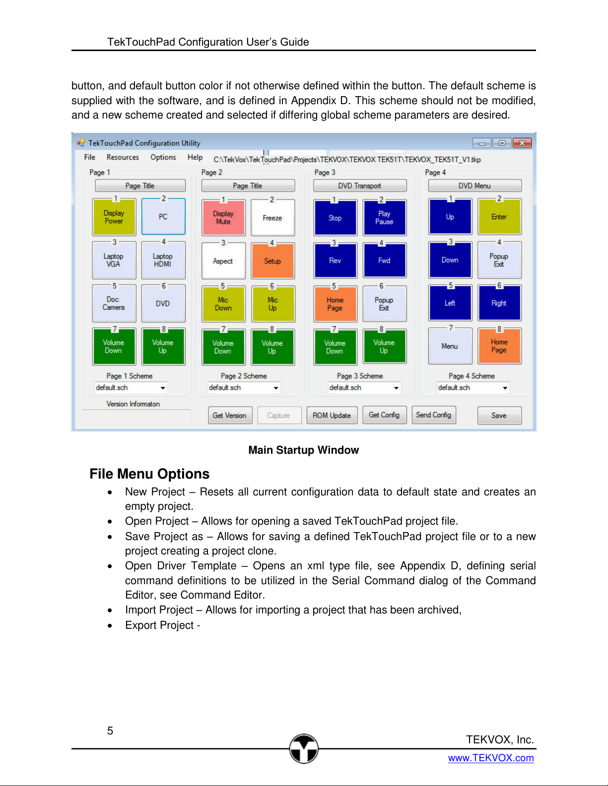
The Main Window
The Main Window is the access point for the majority of the operations of the configuration
utility. It is organized into 4 pages of 8 buttons much like the actual TekTouchPad. This
organization allows for viewing all the defined buttons on one screen alleviating the need to tab
to other pages to verify what has been done. The definitions of resources and file operations are
accessed via the main menu operations, “File” and “Resources”, while communications and
global setup parameters are found in the “options” menu. The “Help” function allows for access
of this document and links to further information. The “Page 1 Scheme – Page 4 Scheme
selections allow for the overall page appearance, specifically defining background color, static
4
Page 5
TekTouchPad Configuration User’s Guide
TEKVOX, Inc.
www.TEKVOX.com
button, and default button color if not otherwise defined within the button. The default scheme is
supplied with the software, and is defined in Appendix D. This scheme should not be modified,
and a new scheme created and selected if differing global scheme parameters are desired.
File Menu Options
New Project – Resets all current configuration data to default state and creates an
empty project.
Open Project – Allows for opening a saved TekTouchPad project file.
Save Project as – Allows for saving a defined TekTouchPad project file or to a new
project creating a project clone.
Open Driver Template – Opens an xml type file, see Appendix D, defining serial
command definitions to be utilized in the Serial Command dialog of the Command
Editor, see Command Editor.
Import Project – Allows for importing a project that has been archived,
Export Project -
Main Startup Window
5
Page 6
Resources Menu Options
Color Schemes – Allows for modifying or creating new color scheme formats.
Assigns a unique ID to the scheme and stores it away with a sch extension.
Bitmaps – Allows for importing bitmaps into the system. Takes a .bmp file and tags it
with a unique ID and adds a tkb extension.
Fonts – Allows for importing fonts into the system. Takes a .bin file and tags it with a
unique ID and adds a tkf extension.
Options Menu Options
Host Com Settings – Sets the current connection communications settings.
Panel System Settings – Allows for setting the global TekTouchPad system settings.
Reset Touch Pad Config – Resets a custom Touch Pad button configuration to
internal default.
Reset Touch Pad Splash – Resets the defined splash screen to no splash screen.
Reset Touch Pad –Causes a Touch Pad reset to occur.
Status View – Provides a report of built in test results from panel self-test.
Path Settings – Sets the locations of the various TekTouchPad files.
Help Menu Options
Contents – Produces this document.
About – Displays the current version and copyright data.
Button Context Menu Options
Right clicking on one of the programmable buttons on the main panel creates a context
menu:
Copy – Copies all configuration data pertaining to the clicked button to the clipboard.
Paste – Pastes all configuration data contained in the clipboard to the selected
button. Button configuration data saved in the clipboard may be pasted into other
instances of the configuration utility.
Clear – Resets the button to its default “Undefined” state. When cleared this button
will not be shown.
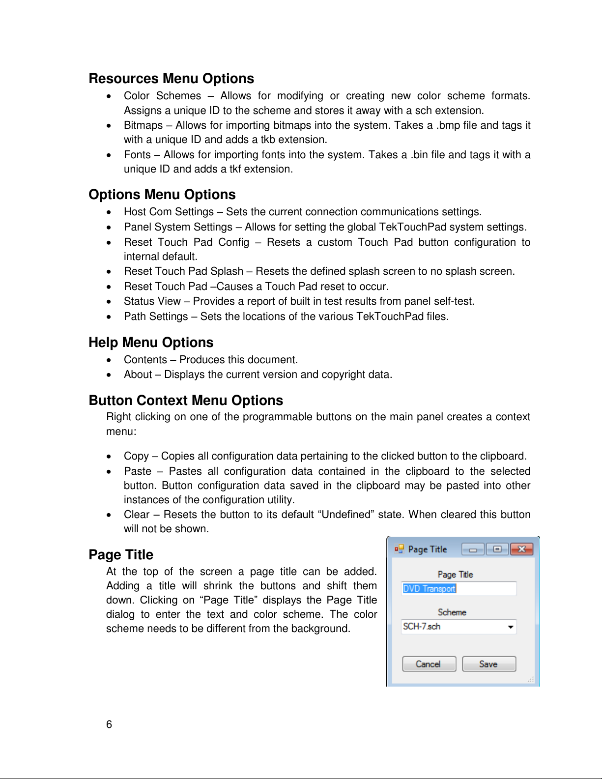
Page Title
At the top of the screen a page title can be added.
Adding a title will shrink the buttons and shift them
down. Clicking on “Page Title” displays the Page Title
dialog to enter the text and color scheme. The color
scheme needs to be different from the background.
6
Page 7

TekTouchPad Configuration User’s Guide
TEKVOX, Inc.
www.TEKVOX.com
The Command Editor
Clicking on any configurable button on the main window will launch the Command Editor. The
Command Editor is the main window for button definition, and includes many facets of button
character and operation described below.
Button ID
This is the ID defined to the button and indicates the page and button number of the
specific button. This value is assigned by the system, and cannot be changed.
Button Label
In order to enable a button for display it must have a name other than “Undefined”. The
Button Label entry is what will appear on the touch screen button when configured. This
label may contain up to two lines of data of varying lengths depending on font size. If the
lengths are too long, the characters will be truncated on the actual button. If it is desired
to disable the button, return the value to “Undefined” or Right-Click to select Clear. If it is
desired to not have any text appear on a button as in the case of a bitmap button, simply
clear the field. Use Ctrl Enter to create a second line.
7
Command Editor Window
Page 8
Type
The type of a button defines the button operational mode and can be; Toggle, Radio, or
Momentary. The Toggle type button will toggle on and off with subsequent pushes. The
Radio button usually belongs to a group of buttons, and when it is pressed, all other
buttons of the same group are released. The Momentary button is only active when it is
pressed, and releases automatically after the touch is removed.
Radio Group
The Radio Group defines the group number associated with a Radio type button and
identifies which buttons belong to the same mutually exclusive group. All other type
buttons default to a 0 group number.
Scheme
The scheme of the button defines the buttons appearance such as normal and selected
coloring along with font information. Schemes are defined through the Resources/Color
Schemes menu option of the main window. The particular defined scheme is then
selected for this button through this window. Schemes create files that are kept in the
project directory and end in .sch. These files can be copied to other project directories to
be used.
Bitmap
The Bitmap selection is used to select a bitmap for the face of a button. This bitmap will
not change when the button is selected or deselected so it is suggested that the scheme
edge colors be significantly different between selected and normal so that a pressed
condition is easily identifiable. Bitmaps are added to the system through the
Resources/Bitmaps menu option of the main window, see Adding Bitmaps. The
particular defined bitmap is then selected for this button through this window item. The
source bitmaps should be defined as 95 x 60 24bit bmp files prior to import. If it is
desired not to have the button label overlay the bitmap during operation, clear all text in
the button label entry field.
Control Group
The Control Group defines a set of mutually exclusive buttons as a collection of controls
to be reset by a single command. This is independent of the Radio Group number, and
defines a “block” of buttons which may span several pages. It is possible to overlap
Control Groups and Radio Groups.
Repeat
The Repeat checkbox inserts the commands for repeating a sequence of commands in
the Press Command Script. Checking this box generates another dialog allowing the
entry of the time interval in 10ms increments between repetitions. The commands
following the Repeat instruction are repeated at the rate defined.
8
Page 9
TekTouchPad Configuration User’s Guide
TEKVOX, Inc.
www.TEKVOX.com
ASCII
The ASCII checkbox allows commands to be displayed in ASCII format. Un-checking
this box defaults to a Hex format display.
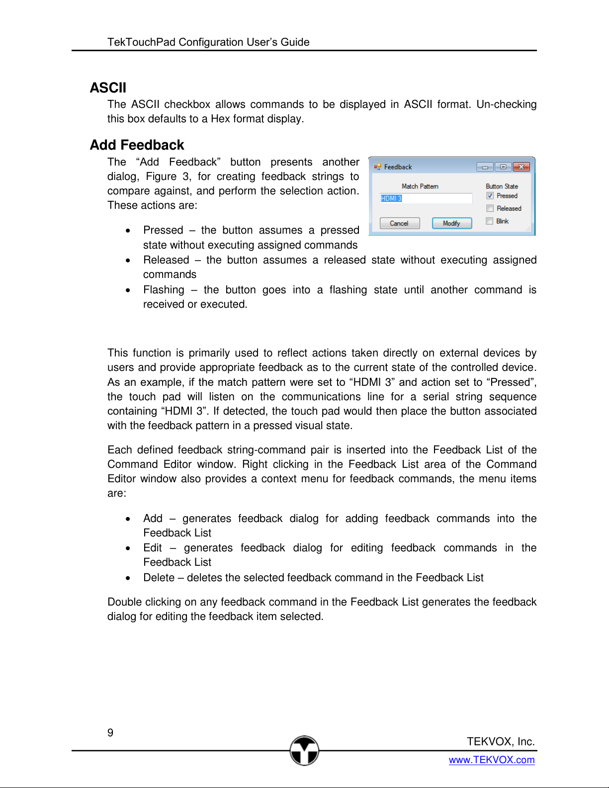
Add Feedback
The “Add Feedback” button presents another
dialog, Figure 3, for creating feedback strings to
compare against, and perform the selection action.
These actions are:
Pressed – the button assumes a pressed
state without executing assigned commands
Released – the button assumes a released state without executing assigned
commands
Flashing – the button goes into a flashing state until another command is
received or executed.
This function is primarily used to reflect actions taken directly on external devices by
users and provide appropriate feedback as to the current state of the controlled device.
As an example, if the match pattern were set to “HDMI 3” and action set to “Pressed”,
the touch pad will listen on the communications line for a serial string sequence
containing “HDMI 3”. If detected, the touch pad would then place the button associated
with the feedback pattern in a pressed visual state.
Each defined feedback string-command pair is inserted into the Feedback List of the
Command Editor window. Right clicking in the Feedback List area of the Command
Editor window also provides a context menu for feedback commands, the menu items
are:
Add – generates feedback dialog for adding feedback commands into the
Feedback List
Edit – generates feedback dialog for editing feedback commands in the
Feedback List
Delete – deletes the selected feedback command in the Feedback List
Double clicking on any feedback command in the Feedback List generates the feedback
dialog for editing the feedback item selected.
9
Page 10
Command List
This list contains the commands which may be associated with a button press or a
button release. They consist of:
Serial Command
Delay
Button Press
Lamp Command
Goto Page
Output
These commands may be inserted into the press or release command script windows by
either dragging and dropping them into their respective lists, or by left or right mouse
double clicks on them. The left mouse double click will insert the command into the
press script list while the right mouse double click will insert the command into the
release script list. Each of these commands will be discussed in further detail below.
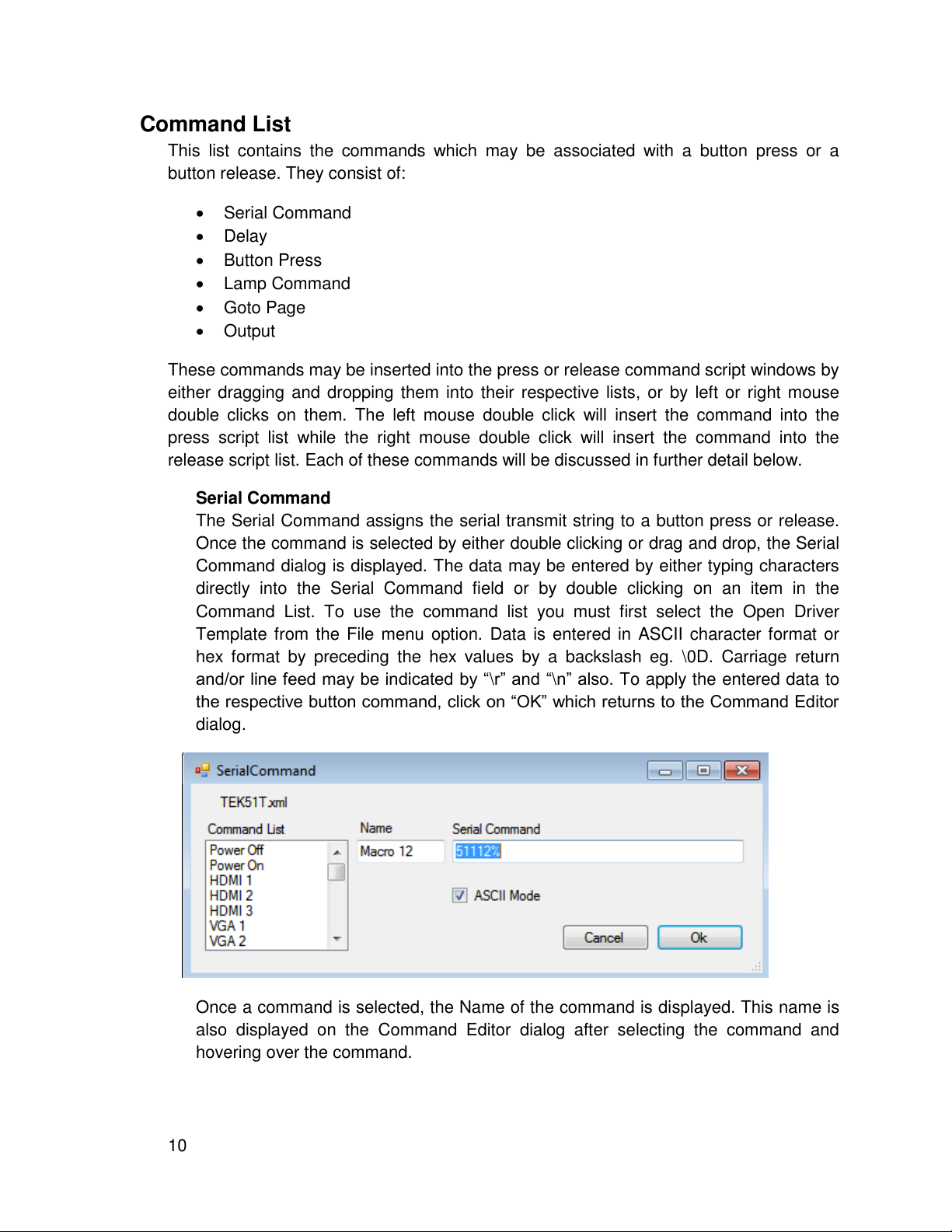
Serial Command
The Serial Command assigns the serial transmit string to a button press or release.
Once the command is selected by either double clicking or drag and drop, the Serial
Command dialog is displayed. The data may be entered by either typing characters
directly into the Serial Command field or by double clicking on an item in the
Command List. To use the command list you must first select the Open Driver
Template from the File menu option. Data is entered in ASCII character format or
hex format by preceding the hex values by a backslash eg. \0D. Carriage return
and/or line feed may be indicated by “\r” and “\n” also. To apply the entered data to
the respective button command, click on “OK” which returns to the Command Editor
dialog.
Once a command is selected, the Name of the command is displayed. This name is
also displayed on the Command Editor dialog after selecting the command and
hovering over the command.
10
Page 11
TekTouchPad Configuration User’s Guide
TEKVOX, Inc.
www.TEKVOX.com
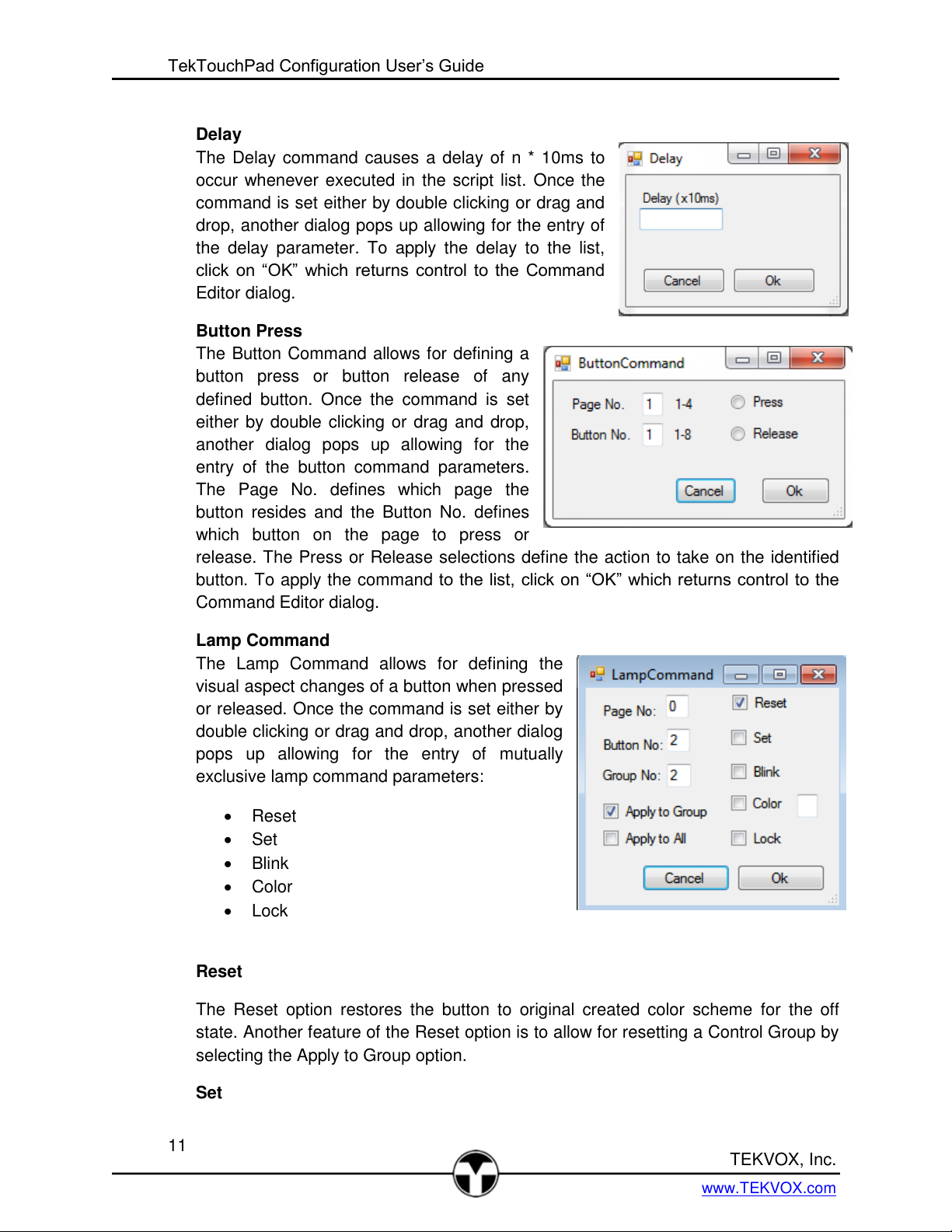
Delay
The Delay command causes a delay of n * 10ms to
occur whenever executed in the script list. Once the
command is set either by double clicking or drag and
drop, another dialog pops up allowing for the entry of
the delay parameter. To apply the delay to the list,
click on “OK” which returns control to the Command
Editor dialog.
Button Press
The Button Command allows for defining a
button press or button release of any
defined button. Once the command is set
either by double clicking or drag and drop,
another dialog pops up allowing for the
entry of the button command parameters.
The Page No. defines which page the
button resides and the Button No. defines
which button on the page to press or
release. The Press or Release selections define the action to take on the identified
button. To apply the command to the list, click on “OK” which returns control to the
Command Editor dialog.
Lamp Command
The Lamp Command allows for defining the
visual aspect changes of a button when pressed
or released. Once the command is set either by
double clicking or drag and drop, another dialog
pops up allowing for the entry of mutually
exclusive lamp command parameters:
Reset
Set
Blink
Color
Lock
Reset
The Reset option restores the button to original created color scheme for the off
state. Another feature of the Reset option is to allow for resetting a Control Group by
selecting the Apply to Group option.
Set
11
Page 12
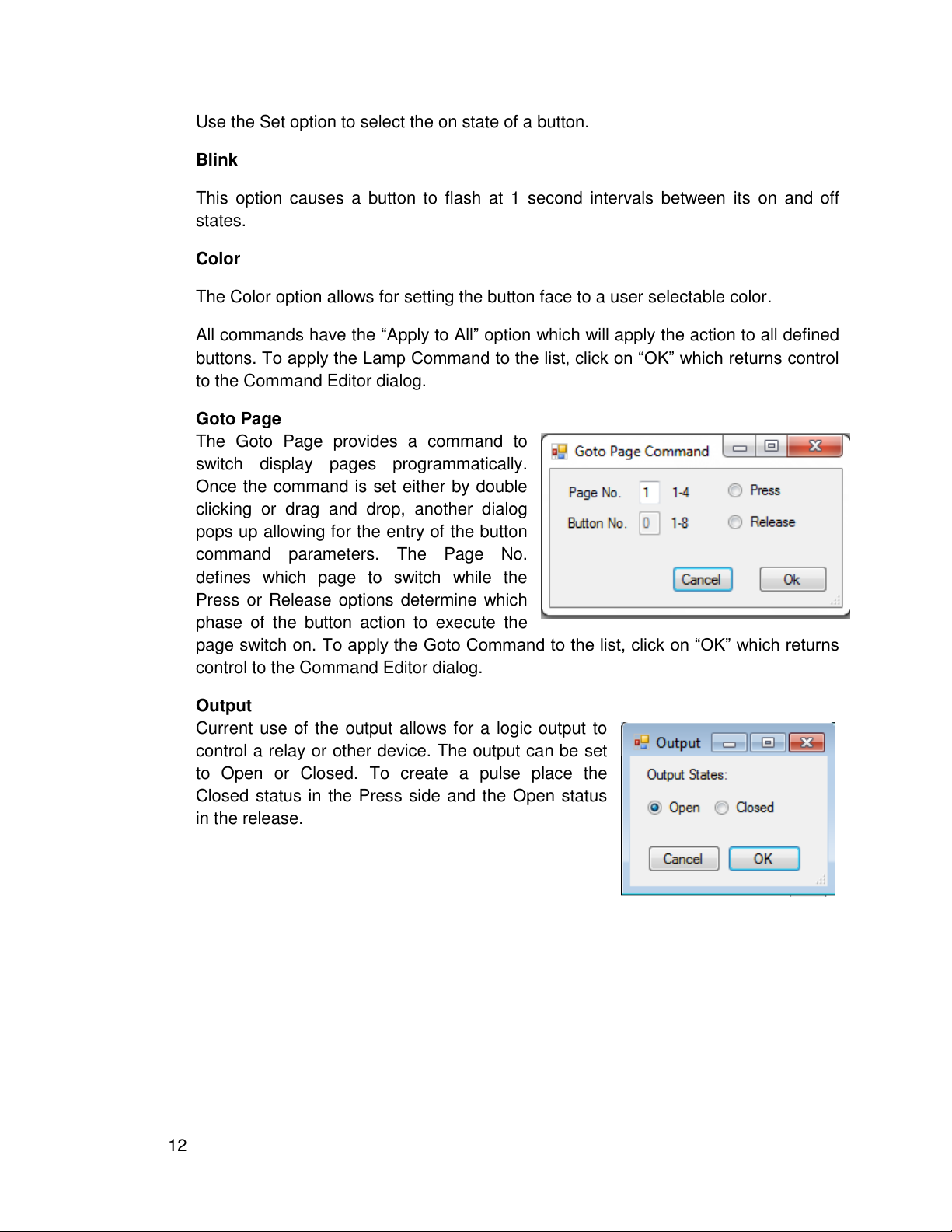
Use the Set option to select the on state of a button.
Blink
This option causes a button to flash at 1 second intervals between its on and off
states.
Color
The Color option allows for setting the button face to a user selectable color.
All commands have the “Apply to All” option which will apply the action to all defined
buttons. To apply the Lamp Command to the list, click on “OK” which returns control
to the Command Editor dialog.
Goto Page
The Goto Page provides a command to
switch display pages programmatically.
Once the command is set either by double
clicking or drag and drop, another dialog
pops up allowing for the entry of the button
command parameters. The Page No.
defines which page to switch while the
Press or Release options determine which
phase of the button action to execute the
page switch on. To apply the Goto Command to the list, click on “OK” which returns
control to the Command Editor dialog.
Output
Current use of the output allows for a logic output to
control a relay or other device. The output can be set
to Open or Closed. To create a pulse place the
Closed status in the Press side and the Open status
in the release.
12
Page 13
TekTouchPad Configuration User’s Guide
TEKVOX, Inc.
www.TEKVOX.com
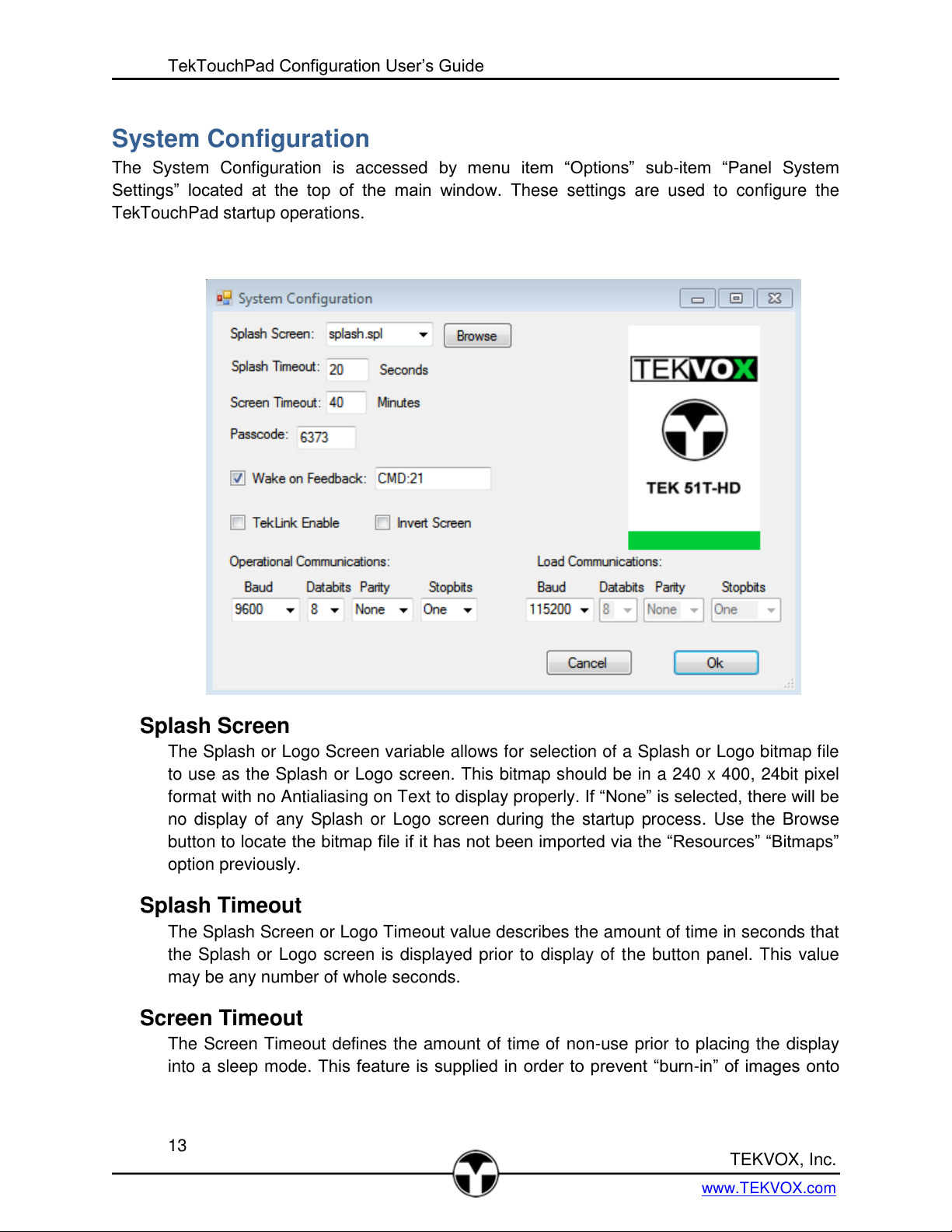
System Configuration
The System Configuration is accessed by menu item “Options” sub-item “Panel System
Settings” located at the top of the main window. These settings are used to configure the
TekTouchPad startup operations.
Splash Screen
The Splash or Logo Screen variable allows for selection of a Splash or Logo bitmap file
to use as the Splash or Logo screen. This bitmap should be in a 240 x 400, 24bit pixel
format with no Antialiasing on Text to display properly. If “None” is selected, there will be
no display of any Splash or Logo screen during the startup process. Use the Browse
button to locate the bitmap file if it has not been imported via the “Resources” “Bitmaps”
option previously.
Splash Timeout
The Splash Screen or Logo Timeout value describes the amount of time in seconds that
the Splash or Logo screen is displayed prior to display of the button panel. This value
may be any number of whole seconds.
Screen Timeout
The Screen Timeout defines the amount of time of non-use prior to placing the display
into a sleep mode. This feature is supplied in order to prevent “burn-in” of images onto
13
Page 14

the LCD screen. This value is delineated in whole minutes, and defaults to 5 although a
more typical value would be around 30 minutes.
Passcode
The Passcode value is a four digit number that defines a unique passcode for this
device, and is typically used for qualifying command or load access to the unit.
TekLink – Future
Invert Screen
When the TekTouchPad is mounted on a wall, its viewing angle is inverted causing
colors to be washed out. To solve this issue you can mount the TekTouchPad upside
down and select Invert Screen.
Operational Communications
The Operational Communications variables define what the communications
configuration should be for the TekTouchPad to control the external device. This is
typically set up for 9600 baud, no parity, 8 data bits, and 1 stop bit. Any configuration
may be defined from these entries and programmed to take effect at the next
TekTouchPad start up. When this is changed from 9600 baud, it is necessary to alos
change the baud in the Host Com Settings the next time you connect to the
TekTouchPad. It is best to leave a note with the TekTouchPad to remind you or the next
person that this TekTouchPad is set to a different baud rate.
Load Communications
The Load Communications variables define what the ROM load communications is for
the TekTouchPad. This is typically set up for 115200, no parity, 8 data bits, and 1 stop
bit in order to decrease loading times for the unit.
Host Com Settings
The Host Com Settings window provides a means of
manually setting the operational and load serial port rates.
Loading bitmaps and ROM updates into the touch pad can
take a long time if the unit is set for the operational rate of
9600 baud. The load rate, which is usually much faster,
provides a means of loading updates and configurations
quickly, and then returning the unit to the operational rate.
The defaults for the touch pad is 9600, none, 8, 1 for the
operational configuration and 115,200, none, 8, 1 for the
load configuration. The load rate is transmitted to the touch
pad at operational speed prior to transitioning to load
parameters. If the load fails, the touch pad will
automatically transition back to the operational rate after 15 seconds.
14
Page 15

TekTouchPad Configuration User’s Guide
TEKVOX, Inc.
www.TEKVOX.com
Creating Schemes
Creating color schemes is one of the powerful features of the TekTouchPad and is accessed by
selection of the menu items “Resources” sub-item “Color Schemes”. The default scheme loaded
as shown gives a starting place for new scheme creation. A Scheme can be edited and saved to
a new file name. Any Scheme file within the project
directory will automatically load into the project. Any
other existent scheme may be loaded using the
“Scheme File” selection at the bottom of the dialog.
The scheme creation dialog allows for two views,
the button view (default) and the panel view. The
button view display what the button would look like
in both pressed and not pressed states. The panel
view displays what a complete panel of 8 buttons
would look like displayed on the TekTouchPad.
When a scheme element is selected for editing, a
color dialog appears allowing for selection of a color
or definition of a custom color. Each of the scheme
elements is described below:
Note: The TekTouchPad utilizes 16 bit RGB 565 color definition, and translates between the 24
bit and 16 bit orientation. This may result in the actual displayed color potentially being off from
the originally selected color. It is best to test the created colors on a single button of the actual
unit prior to full panel definitions.
Background – Defines the background color of the button page. Each button
page may have a different color if so desired. The background color is only used
for page schemes selected from the main window.
Normal Face – Defines the button face color in an off state.
Selected Face – Defines the button face color in a pressed state.
Normal Text – Defines the color used for the normal face text color in an off
state.
Selected Text – Defines the color used for the selected pressed button face text
Disabled – Defines the color used for a disabled button
Shadow Edge – Defines the color used for in an off state shadowed edge. This
edge is usually the bottom edge of a non-pressed button, and is darker than the
shine upper edge.
Shine Edge – Defines the color used for in an off state button shining edge. This
edge is usually the top edge of a non-pressed button, and is a lighter shade of
the shadow edge color.
Set Shadow Edge – Defines the color used for a selected pressed button
shadowed edge. This edge is typically the top edge of a selected button, and is a
15
Page 16

darker shade of the shine bottom edge color. This color may be the same as the
Shine Edge color in non-bitmap type buttons.
Set Shine Edge – Defines the color used for a selected pressed button shining
edge. This edge is typically the bottom edge of a selected button, and is a lighter
shade of the shadow top edge color. This color may be the same as the Shadow
Edge color in non-bitmap type buttons.
Once all the desired colors have been selected, the defined scheme may be saved by
clicking the “Save” button, and entering a new file name, or saving into an existing file
name. When a scheme is saved, it is allocated a unique ID number attached to the
name. This allows for determining differing schemes based on an original scheme of the
same name. The “Update ID button is an advanced option, and is used for correcting
schemes with duplicated IDs, see Appendix G - Troubleshooting Guide.
Adding Bitmaps
The Bitmap Selection dialog may be accessed via the
menu items “Resources” sub-item “Bitmaps”. This
launches a dialog for importing existent bitmaps for use
in the TekTouchPad system. If the bitmap desired is
located in the
ProgramData/TEKVOX/TekTouchPad/Bitmaps
directory, it will show up in the selection list for import.
Bitmaps are then imported by selecting a bitmap in the
selection list, and clicking “Add” on the lower list. This
action will assign a unique ID number to the bitmap file
name allowing for versions of the same bitmap.
Any imported bitmaps may also be removed by selecting an imported bitmap in the lower list
and clicking “Delete”. Bitmaps outside of the program data directory may be selected by using
the “Browse” button to select them. Once a bitmap is selected, it is displayed in a side window
as show in the Figure. Selecting an imported bitmap will also display in the side window.
Bitmaps for buttons may be created through any paint program and should have a 95 x 60, 24
bit color bmp format.
16
Page 17

TekTouchPad Configuration User’s Guide
TEKVOX, Inc.
www.TEKVOX.com
Adding Fonts
The Font Selection dialog may be accessed via the
menu items “Resources” sub-item “Fonts”. This
launches a dialog for importing existent fonts for use
in the TekTouchPad system. If the font desired is
located in the ProgramData/TEKVOX/TekTouchPad/
Fonts directory, it will show up in the selection list for
import. Fonts are then imported by selecting the
desired font in the upper list, and clicking “Add” on
the lower list. This action will assign a unique ID
number to the font file name allowing for versions of
the same font. Any imported fonts may also be
removed by selecting an imported font in the list and
clicking “Delete”. Fonts outside of the program data
directory may be selected by using the “Browse”
button to select them. Refer to Appendix B for the list
of system supplied fonts, and methods to import
additional fonts.
Updating the Firmware
Occasionally there is a need to upgrade the main firmware of the unit. Before starting the
process get the latest firmware by selecting “Get Updates” in the Option menu. You must have
an internet connection.
Before sending the new firmware it is best to make
certain you have the correct serial port settings and
wire connections made by getting the ROM version
by pressing the “Get Version” button. If the ROM version is not returned and the Time Out
message is displayed, you need to check for the correct Com Port and connections. From the
PC the RS-232 cable requires a Null Female to Female cable. If you are not certain the ROM in
the TekTouchPad is not the latest, go ahead and updated the ROM by pressing “ROM Update”.
When using a USB to serial, it is necessary to determine the correct Com port. This can be
found in Device Manager under ports.
17
Page 18

To load new firmware click on the “ROM Update” button
located on the bottom of the main panel. A load progress
dialog will appear giving the number of blocks loaded.
Typically 400 blocks are required for a full ROM update.
Once the load is completed, the progress window
disappears, and the TekTouchPad resets.
Downloading the Configuration
Once all the schemes, bitmaps, fonts, and button definitions have been completed, the project
may then be sent to the TekTouchPad. Before sending the project it is best to make certain you
have the correct serial port settings and wire
connections made by getting the ROM version
by pressing the “Get Version” button. If the ROM
version is not returned and the Time Out message is displayed, you need to check for the
correct Com Port and connections. From the PC the RS-232 cable requires a Null Female to
Female cable. If you are not certain the ROM in the TekTouchPad is not the latest, go ahead
and updated the ROM by pressing “ROM Update”.
To load the project into the TekTouchPad, click on the
“Send Config” button on the lower main screen. If
communications is correct, the DownloadSetup dialog
is displayed. This dialog allows for the selection of the
items you need to send to the TekTouchPad. By
default the Configuration Data and Splash Screen
(Logo page) are selected. These are the only two you
need unless you are adding bitmaps and fonts. If the
splash screen is already loaded, the Splash Screen
selection can be deselected which speeds up the
loading process. A warning dialog will then come up
prior to actually changing TekTouchPad configuration. Click on “OK” to start the download.
While loading the load process popup is displayed
showing the blocks sent to the TekTouchPad.
18
Page 19

TekTouchPad Configuration User’s Guide
TEKVOX, Inc.
www.TEKVOX.com
Uploading the Configuration
On occasion, it becomes necessary to recover project files from the TekTouchPad. The system
provides this feature using the “Get Config” feature. Clicking this button displays a file location
dialog for creating the folder where to place the retrieved files. Another “GetConfig” dialog is
displayed prompting the user for the type of data items
to retrieve. Once the desired items are selected, click
on the “Get Data” button which will then retrieve each
of the types of data items, listing them in the “Loaded
Files” area, and saving them to the program data
directory. Any files uploaded which are duplicates of
existing files, such as bitmap files, are appended with a
character A-Z until the conflict is resolved. This same
process is followed for the Font and Splash/Logo files.
Pressing the “Save” button creates a new project with
the retrieved configuration script.
Notes:
The Splash Screen is not loaded into the new project and will need to be manually loaded by
selecting it from the “Panel System Settings” in the Option menu. A warning message is
displayed about not finding the Splash Screen.
The color schemes will not be listed by their original name but listed by a number.
Touch Calibration
The touch screen is pre-calibrated by TEKVOX prior to shipping. Occasionally, however, it may
become necessary to recalibrate the touch module if touch accuracy has become degraded or
the unit is loaded with an inverted project. This is accomplished by resetting the unit while
keeping a constant touch pressure on the screen forcing the unit into calibration mode. Follow
the screen instructions on completing the calibration process.
Notes:
It is usually preferable to touch the calibration points with a stylus smaller than the calibration
points to achieve the best accuracy.
To reset the unit, toggle power to the system, or if that is impractical, send the “~~R” command
to the unit via serial port to initiate a reset command, see Appendix D.
19
Page 20

Button Configuration Strategies
In working towards a new screen layout, there are some strategies that can be taken to help
with the button page creation. The first step is to draw out what buttons are needed. Secondly,
work on button groupings, are some buttons dependent on the operation of others. Thirdly,
identify what the button operational characteristics are; toggle, momentary, or radio type
grouped buttons. After identifying the button groupings, it should be decided how the largest
button group should be oriented. Will the largest grouping fit on one page, or spread across
several pages, occupying specific rows. Common commands may be repeated on one row of
each page for availability such as the volume control. Other approaches may confine specific
functionality on each page eg. source selection on one page, control commands on the second
page, and possibly lighting controls on the third page.
The Scheme definitions for each button or group of buttons should be such that contrast
between the face color and the text color is highest for ease of identification. This may require
different text colors for selected and non-selected buttons to improve readability across button
states.
20
Page 21

TekTouchPad Configuration User’s Guide
TEKVOX, Inc.
www.TEKVOX.com
Using bitmaps for button images takes a slightly different approach. After saving the desired
bitmaps using the “Adding Bitmaps” function, click on the button to edit from the main window
which then enters the Command Editor. Select the bitmap from the bitmap selection box on the
Command Editor dialog. Remove any text for the Button Label entry to prevent overwriting on
the bitmap as shown below. Once the rest of the button functionality is defined, click on the “OK”
button to return to the main screen which should now hold the new bitmap button image.
Remember to choose schemes with border edges that will differentiate between pressed and
not pressed since the bitmaps will remain constant between the two states.
21
Page 22

Bitmap Buttons
Bitmap Button with Selected Border
22
Page 23

TekTouchPad Configuration User’s Guide
TEKVOX, Inc.
www.TEKVOX.com
Quick Start Guide
The following is a simple procedure to start working with the TekTouchPad.
Updating firmware
1. Before starting the process get the latest firmware by selecting “Get Updates” in the
Option menu. You must have an internet connection.
2. When using a USB to serial, it is necessary to determine
the correct Com port. This can be found in Device
Manager under ports.
3. Open the “Host Com Setting” in the Option menu and
select the correct comport
4. Check for connection by pressing the “Get Version” button.
If the ROM version is not returned and the
Time Out message is displayed, you need to
check for the correct Com Port and
connections. From the PC the RS-232 cable
requires a Null Female to Female cable.
5. To load new firmware click on the “ROM Update”
button located on the bottom of the main panel. A
load progress dialog will appear giving the number
of blocks loaded. Typically 400 blocks are required
for a full ROM update. Once the load is
completed, the progress window disappears, and
the TekTouchPad resets.
Creating and loading a touch panel configuration
1. Connect the TekTouchPad to a power source and host computer via the supplied
interface cable and a Female to Female null adaptor.
2. Launch the TekTouchPad Configuration utility from the desktop icon. The startup screen
should appear as shown below with the default color scheme loaded for each of the four
button pages.
3. From the Option menu select “Get Updates”.
23
Page 24

4. From the File Menu select “Open Driver Template” and select the device you are
working with. For this demonstration we will select TEK51T.xml.
Main Startup Screen
5. Click on the menu option “File” and then “New Project”. Enter a name for the test project
and click “OK”.
6. Click on button 1 of page 1. A window should appear as shown as below, with the
default scheme loaded, and the current button label set to “undefined”.
Command Editor Screen
24
Page 25

TekTouchPad Configuration User’s Guide
TEKVOX, Inc.
www.TEKVOX.com
7. Click into the “Button Label” box, and replace “undefined” with the desired label
nomenclature, in this case “TEST”. Typically with the default font, you may enter up to 9
characters per line. Use the carriage return to enter a second line if desired.
8. Double click on the “Serial Command” option located in the left window. A new window
will appear allowing for ASCII command data entry and select the command you want
the button to send when pressed. You can also enter your own commands.
Serial Command Screen after adding ASCII command characters
Note: The “\0D” or “\r” is the nomenclature for inserting a carriage return while “\0A” or
“\n” would be used for a line feed.
25
Command Editor Screen after changes made
Page 26

9. Click “OK” on the “Command Editor” window to apply the settings and return you to the
main screen. Your new button label should now appear on the selected button as
shown.
Main Screen after changes made
10. Now select the “SendConfig” button to send the
defined data to the TekTouchPad. Another window
will appear listing the dependencies required for
this configuration. There should not be any listings
since we are not defining any custom bitmaps or
fonts.
11. Make sure only “Configuration Data” is
selected, and then click the “OK” button.
Again click “OK” on the warning, and the
unit should load very quickly. Once
loaded, the unit will reset, and the
configuration just defined should appear
with only one button enabled as show.
26
Page 27

TekTouchPad Configuration User’s Guide
TEKVOX, Inc.
www.TEKVOX.com
Appearance of Configured TekTouchPad
27
Page 28

Interconnect Diagram
Model
TekTouchPad (78034)
LCD
a-Si color TFT LCD, Normally white type
Screen Size
3.0 inch WQVGA
Display Format
240*RGB*400 Stripe type
Backlight
White LED
Viewing Direction
12 O’clock
Viewing Area
1.5”x2”
Voltage Range
12-24 Volts
Temperature and humidity
0-60 ℃(Temperature),0-95% RH
Size
W: 2.77 in / H: 4.28 in / D:.73
Weight
0.2 lbs / 1.00 lbs Package
Appendix A – Specifications
28
Page 29

TekTouchPad Configuration User’s Guide
TEKVOX, Inc.
www.TEKVOX.com
Appendix B – Breakout Cable
29
Page 30

Appendix C – Importing Fonts
The supplied TekTouchPad system includes basic fonts to use in button labeling
including:
Internally (included in firmware) supplied fonts:
Generic Small Font 9pt.
Generic Medium Font 12pt.
Generic Large Font 24pt.
Gentium 14pt
Externally (included in install directory) supplied fonts:
Arial 12pt.
Arial 14pt.
Arial 18pt.
Calibri 12pt
Calibri 14pt
Calibri 18pt
Sans Serif 12pt
Sans Serif 14pt
Sans Serif 18pt
Times New Roman 12pt
Times New Roman 14pt
Times New Roman 18pt
Occasionally there is a need to add to the basic library of fonts. In order to accomplish
this, an external utility, the Graphics Resource Converter, provided by Microchip will be
required. This external utility may be obtained from the TEKVOX software download
page. Launch the converter application and click on the “Add Fonts” button. From the file
selection window, navigate to the C:\Windows\Fonts directory, and choose from the
available fonts. Once a true type font is selected, another window appears allowing
selection of font size and other attributes. Make the appropriate selections and click
“OK”. This will return to the main screen from which you now click on the “Convert”
button. This will ask for a file name and type. Navigate to the
“ProgramData\TEKVOX\TekTouchPad\Fonts” directory, select “Binary (*.bin)” from the
30
Page 31

TekTouchPad Configuration User’s Guide
TEKVOX, Inc.
www.TEKVOX.com
“Save as Type” options, and type in an appropriate name for the converted font. Finally,
click “Save” to complete the conversion, a “Converted Successfully” message should
appear confirming the operation. The converted font should now be available for import
into the system via “Resources/Fonts” menu options, see Adding Fonts.
Graphics Resource Converter
Selection Sub Font
31
Page 32

Appendix D – Interactive Touch Pad Protocol
General Commands Description
~~V<CR> Gives the Version of the firmware, returns: V s.s,h.h<CR><LF> where s.s
is the firmware version and h.h is the hardware version.
~~Gt Get Data command where t = type of data
Values for t:
C – Get configuration data
B – Get bitmap data
F – Get font data
S – Get logo data
Transfer format:
<SOH, Length MSB, Length LSB, Data ….., EOT>
Host responds with ACK when ready for next block until <Length> data received or time
out. The current time out value is 15 seconds. Block size is 512 bytes of data. <DLE> is
used for transferring raw data not intended to be interpreted as SOH or EOT.
SOH = 0x01, EOT = 0x04, DLE = 0x10, ACK = 0x06, NAK = 0x15
~~R Causes unit to reset
~~? Ping unit, returns “OK<CR><LF>”
~~<n Change the loader baud rate. The value n is an index for the baud rate desired:
0 – 9600, 1 – 19200, 2 – 38400, 3 – 56800, 4 – 115200.
~~S Report self test results
~~W Wake unit if in sleep mode
Button Commands
~~BPpb Causes button pb to be pressed where p = page number, b = button
number
~~BRpb Causes button pb to be released where p = page number, b = button
number
~~BSpb Causes the state of button pb to be returned, p = 'A' returns all buttons
32
Page 33

TekTouchPad Configuration User’s Guide
TEKVOX, Inc.
www.TEKVOX.com
Returns: BpbSs where p = page number, b = button number, s = state 1 = pressed, 0 =
released
Lamp Commands
~~LGg Causes all buttons of group g to be released, blink disabled, and colors to
return to default state
~~LRpb Causes button pb to be released, blink disabled, and colors to return to
default state where p = page number and b = button number. An 'A' for p
causes ALL buttons to return to default state.
33
Page 34

Appendix E – XML Driver File Format Example
<?xml version="1.0"?>
-<MT_Command_Template> -<Device> <Type>SWITCHER</Type>
<Make>TEKVOX</Make> <Model>TEK-902HD_SERIAL</Model> </Device>
<Volume_Steps/> -<Serial_Port_Settings> <Baud_Rate>9600</Baud_Rate>
<Data_Bits>8</Data_Bits> <Parity>N</Parity> </Serial_Port_Settings> -
<S_Command_Record> <Name>HDMI 1</Name>
<Command_String>0701%</Command_String> </S_Command_Record> -
<S_Command_Record> <Name>HDMI 2</Name>
<Command_String>0702%</Command_String> </S_Command_Record> -
<S_Command_Record> <Name>VGA 1</Name>
<Command_String>0703%</Command_String> </S_Command_Record> -
<S_Command_Record> <Name>VGA 2</Name>
<Command_String>0704%</Command_String> </S_Command_Record> -
<S_Command_Record> <Name>COMP 1</Name>
<Command_String>0705%</Command_String> </S_Command_Record> -
<S_Command_Record> <Name>COMP 2</Name>
<Command_String>0706%</Command_String> </S_Command_Record> -
<S_Command_Record> <Name>S-Video</Name>
<Command_String>0707%</Command_String> </S_Command_Record> -
<S_Command_Record> <Name>Video 1</Name>
<Command_String>0708%</Command_String> </S_Command_Record> -
<S_Command_Record> <Name>Video 2</Name>
<Command_String>0709%</Command_String> </S_Command_Record> -
<S_Command_Record> <Name>800X600 SVGA</Name>
<Command_String>0711%</Command_String> </S_Command_Record> -
<S_Command_Record> <Name>1024X768 XGA</Name>
<Command_String>0712%</Command_String> </S_Command_Record> -
<S_Command_Record> <Name>81280X1024 SXGA</Name>
<Command_String>0713%</Command_String> </S_Command_Record> -
<S_Command_Record> <Name>1280X800 WXGA</Name>
<Command_String>0714%</Command_String> </S_Command_Record> -
<S_Command_Record> <Name>1280X720 720P</Name>
<Command_String>0715%</Command_String> </S_Command_Record> -
<S_Command_Record> <Name>1920X1200 UXGA</Name>
<Command_String>0716%</Command_String> </S_Command_Record> -
<S_Command_Record> <Name>1920X1080 1080P</Name>
<Command_String>0717%</Command_String> </S_Command_Record> -
<S_Command_Record> <Name>1920X1200 WUXGA</Name>
<Command_String>0718%</Command_String> </S_Command_Record>
</MT_Command_Template>
34
Page 35

TekTouchPad Configuration User’s Guide
TEKVOX, Inc.
www.TEKVOX.com
Appendix F – default.sch
Font: Gentium 14pt
Background Color – RGB(0,0,0)
Normal Face Color – RGB(255,255,255)
Selected Face Color – RGB(0,128,248)
Normal Text Color – RGB(0,0,0)
Selected Text Color – RGB(0,0,0)
Disabled Color – RGB(208,208,208)
Shadow Edge Color – RGB(168,168,168)
Shine Edge Color – RGB(208,208,208)
Selected Shadow Edge Color – RGB(128,128,128)
Selected Shine Edge Color – RGB(192,192,192)
35
Page 36

Appendix G – Troubleshooting Guide
Program Startup Errors:
Occasionally when schemes or bitmaps are copied into the program data directory, ID collisions
may occur, and a warning such as below may appear.
If both schemes are utilized, then say yes to keep the duplication, but we will have to fix this
later. To correct the problem, decide which scheme is less used and edit that scheme. After
loading the scheme into the editor, save it again, and when asked to update the ID, say yes.
The projects that use this scheme will need to be updated to use this new ID’d scheme, else
they will use the other duplicate ID scheme not originally intended for the project.
Resources – Bitmaps Errors:
When selecting a bitmap from the “Bitmap to Add” list the error occurs:
Or when selecting a bitmap from the “Browse” list the error occurs:
36
Page 37

TekTouchPad Configuration User’s Guide
TEKVOX, Inc.
www.TEKVOX.com
This indicates a bad .bmp format, and the file should be replaced.
Command Editor Errors:
When clicking “OK” on Command Editor:
This error indicates that a special hex character was added to a label, but was an invalid hex
character eg. /oD instead of \0D.
When clicking “OK” on Delay sub command dialog:
Or
This indicates that an invalid numeric or too large a numeric was entered for the delay value.
37
Page 38

This error indicates that a scheme for the button was not selected. Select “default” if no
particular scheme is desired.
This error occurs when a page number entered falls beyond the defined page numbers 1-4.
Correct the number to fall within the legal range.
This error occurs when the button number entered falls out of the defined button range 1-8.
Enter a valid button number within the defined range.
38
Page 39

TekTouchPad Configuration User’s Guide
TEKVOX, Inc.
www.TEKVOX.com
System Configuration Errors:
This error indicates that an invalid numeric was entered into the timeout or passcode boxes.
The splash or logo screen should be imported into the system using the System Configuration
“Browse” button. If the file is directly copied into the program data directory without a unique ID
assignment, this error occurs. Delete the file from the program data directory and import it using
the Browse button.
SendConfig Errors:
This error indicates that the default.sch file expected is not present in the system. Usually, this
means that the ID assigned to this scheme differs from the default used in a project. The best
way to fix this is to find the original project default scheme, rename it, and reassign this new
scheme to the occurrences of the default in the project.
39
Page 40

This error indicates that a specific bitmap selected for a project is no longer available. Find the
appropriate bitmap, re-import it, if necessary, and then re-assign it to the specific button(s) as
required.
This error indicates that a specific font selected for a project is no longer available. Find the
appropriate font, re-import it, if necessary, and then re-assign it to the specific scheme(s) as
required.
This error indicates that the expected splash/logo file was not found. Re-import the file and re-
assign to project using System Configuration.
40
Page 41

TekTouchPad Configuration User’s Guide
TEKVOX, Inc.
www.TEKVOX.com
This error indicates that the requested port is already in use by some other application. Select
another port utilizing the Host Com Settings menu option.
This error indicates that the system was not able to communicate with the unit. Check cabling
and Host Com Settings to make sure the operational rates are set correctly.
Note: This is an operational rate failure, and has nothing to do with load rates.
This error indicates that the operational rate negotiations passed, but the load rate transactions
failed. This is usually caused by a load rate com settings mismatch. Make sure the Loader
settings in the Host Com Settings is set to 115200 baud, no parity, 8 data bits, and 1 stop bit.
41
Page 42

This error indicates that the attempt to take the TekTouchPad back to operational settings from
load settings failed. The TekTouchPad will automatically reset these values back to operational
settings within 10 seconds of load stall, so just waiting this period will allow for restarting this
process.
Help – Contents Errors:
This error indicates that the help pdf file was not located. This file should resided in the
C:\ProgramData\TEKVOX\TekTouchPad\Documents directory. If not there, try re-installing
software.
ROMUpdate Errors:
The firmware file was not found in the C:\ProgramData\TEKVOX\TekTouchPad directory. Try
re-downloading drivers.
42
Page 43

TekTouchPad Configuration User’s Guide
TEKVOX, Inc.
www.TEKVOX.com
Some Additional Errors:
Error: Could not read file from disk.
This error is usually caused by permissions not granted to user. Check user permissions on
ProgramData/TEKVOX/TekTouchPad directory.
Improper operational response from unit:
This error is caused by a handshaking problem between the host and the TekTouchPad. Make
sure COM settings are correct, and cabling is solid. If trying to load from operational code, try to
load from bootloader code as described in the ROM Update section.
Upload failure with:
This error is caused by a non-response from the TekTouchPad when transitioning to the load
rate. Make sure the load rate is correct in the Host COM Settings.
43
 Loading...