

Page 1
1 / 49
4K 7x1 Multiviewer Switcher
(TEK MV71-4K 79064 & 79065)
User Manual
All Rights Reserved
Revised July 1, 2015
Page 2

2 / 49
Preface
Read this user manual carefully before using this product. Pictures shown in this
manual are for reference only. Different model and specifications are subject to real
product.
This manual is only for operation instruction only, not for any maintenance usage. The
functions described in this version are recent as of January 2015. Any changes to
functions and parameters since then will be updated separately. Please refer to your
dealer for the latest details.
Trademarks
Product model and logo are trademarks. Any other trademarks mentioned in this
manual are acknowledged as the properties of the trademark owner. No part of this
publication may be copied or reproduced without prior written consent.
FCC Statement
This equipment generates, uses, and can radiate radio frequency energy and, if not
installed and used in accordance with the instructions, may cause harmful
interference to radio communications. It has been tested and found to comply with the
limits for a Class A digital device, pursuant to part 15 of the FCC Rules. These limits
are designed to provide reasonable protection against harmful interference in a
commercial installation.
Operation of this equipment in a residential area is likely to cause interference, in
which case the user at their own expense will be required to take whatever measures
may be necessary to correct the interference.
Any changes or modifications not expressly approved by the manufacture will void the
user’s authority to operate the equipment.
Page 3

3 / 49
SAFETY PRECAUTIONS
To insure the best from the product, please read all instructions carefully before using
the device. Save this manual for further reference.
l Unpack the equipment carefully and save the original box and packing material for
possible future shipment
l Follow basic safety precautions to reduce the risk of fire, electrical shock and injury
to persons.
l Do not dismantle the housing or modify the module. It may result in electrical shock
or burn.
l Using supplies or parts not meeting the products’ specifications may cause
damage, deterioration or malfunction.
l Refer all servicing to qualified service personnel.
l To prevent fire or shock hazard, do not expose the unit to rain, moisture or install
this product near water.
l Do not put any heavy items on the extension cable in case of extrusion.
l Do not remove the housing of the device as opening or removing housing may
expose you to dangerous voltage or other hazards.
l Install the device in a place with fine ventilation to avoid damage caused by
overheat.
l Keep the module away from liquids.
l Spillage into the housing may result in fire, electrical shock, or equipment damage.
If an object or liquid falls or spills on to the housing, unplug the module
immediately.
l Do not twist or pull by force ends of the optical cable. It can cause malfunction.
l Do not use liquid or aerosol cleaners to clean this unit. Always unplug the power to
the device before cleaning.
l Unplug the power cord when left unused for a long period of time.
l Information on disposal for scrapped devices: do not burn or mix with general
household waste, please treat them as normal electrical wastes.
Page 4

4 / 49
Feature List
l Multiple inputs: 4 x HDMI, 2 x DisplayPort, 1 x RGB/YPbPr
l HDMI,DisplayPort source input with 4Kx2K@30Hz support
l Supports MHL in the four HDMI input ports
l Supports multiple HDMI output resolutions, such as 4Kx2K@30Hz and 1080P.
l Supports Auto Scaler in each source input
l Supports different multiple-window modes of quadruple windows, triple windows,
double windows and a single window, outputting to a display device through one
HDMI output
l Supports pre-defined multiple-window mode
l Supports breakaway audio
l HDCP compliant
l Fast switch between input ports
l Supports audio 7 x 1
l Supports multiple-channel HDMI, DisplayPort audio extraction, optical fiber and
eight-channel analog outputs
l Supports one-key fast switch and all-round display through HDMI/DisplayPort
Cable Switch
l Easy-to-use panel and Web GUI
l Chooses from four control methods – Panel, IR, IP (Web GUI, Telnet & UDP) and
RS232
l On-site firmware upgrading through USB port.
l 1U size design
Page 5

5 / 49
Contents
Getting'Started'.......................................................................................................................................................'7'
Panel'Layout'........................................................................................................................................................'7'
Front'Panel'......................................................................................................................................................'7'
Back'Panel'.......................................................................................................................................................'8'
IR'Remote'Control'U nit'.......................................................................................................................................'9'
Button'layout'..................................................................................................................................................'9'
HDMI/DP'Cable'Switcher'(Optional)'................................................................ .................................................'10'
Installation'........................................................................................................................................................'10'
How'to'Connect'the'Multiviewer'Switcher'...................................................................................................'10'
Wiring'Diagram'.............................................................................................................................................'11'
Operating'..............................................................................................................................................................'12'
Standby'Mode'and'Operational'Mode'.............................................................................................................'12'
Screen'layout'Configuration'.............................................................................................................................'12'
Single'Window'..............................................................................................................................................'15'
Double'Windows'...........................................................................................................................................'16'
Triple'Windows'.............................................................................................................................................'17'
Quadruple'Windows'.....................................................................................................................................'18'
Output'Resolution'.............................................................................................................................................'19'
Audio'Setting'.....................................................................................................................................................'19'
Audio'Input'Select'.........................................................................................................................................'19'
Audio'Output'Instructions'............................................................................................................................'21'
OSD'Setting'Instructions'...................................................................................................................................'21'
Advanced'Settings'.................................................................................................................................................'25'
RS232'Setting'....................................................................................................................................................'25'
IP'Setting'...........................................................................................................................................................'26'
Command'List'...................................................................................................................................................'28'
Source'Control'..............................................................................................................................................'29'
Video Input Select by Viewer ...................................................................................................... 29'
Audio Source Selection .............................................................................................................. 30'
Volume Control ........................................................................................................................... 31'
Page 6

6 / 49
Aspect Ratio Selection ............................................................................................................... 31'
Resolution Selection ................................................................................................................... 32'
Advanced'Control'.........................................................................................................................................'32'
Power Control ............................................................................................................................. 32'
Audio Delay ................................................................................................................................ 33'
System Controls ......................................................................................................................... 33'
EDID'Management'........................................................................................................................................'35'
Copy Preset EDID ...................................................................................................................... 36'
Copy EEPROM EDID ................................................................................................................. 37'
Write EDID Name (EEPROM) .................................................................................................... 38'
Read EDID Name (EEPROM) .................................................................................................... 38'
Write EDID Data to (EEPROM) .................................................................................................. 38'
Read EDID Data from (EEPROM) .............................................................................................. 39'
Read EDID Data from Output ..................................................................................................... 39'
Copy EDID Data from Output ..................................................................................................... 39'
WEB'Setting'......................................................................................................................................................'40'
General'Settings'............................................................................................................................................'40'
Screen Layout Selection ............................................................................................................. 41'
Video Input Selection .................................................................................................................. 41'
Aspect Ratio ............................................................................................................................... 41'
Audio Input ................................................................................................................................. 42'
Audio Volume: ............................................................................................................................ 43'
Output Timing: ............................................................................................................................ 43'
Advanced'Settings'.........................................................................................................................................'44'
Power Switch Selection .............................................................................................................. 44'
Audio Mute Selection .................................................................................................................. 45'
Auto Position Setting .................................................................................................................. 46'
Restore to default Setting ........................................................................................................... 46'
Serial Baud Rate Setting: ........................................................................................................... 46'
Other'.....................................................................................................................................................................'47'
F/W'Update'.......................................................................................................................................................'47'
Specifications'....................................................................................................................................................'48'
Relative'Products'Series:'...................................................................................................................................'49'
Page 7
7 / 49
Getting Started
Panel Layout
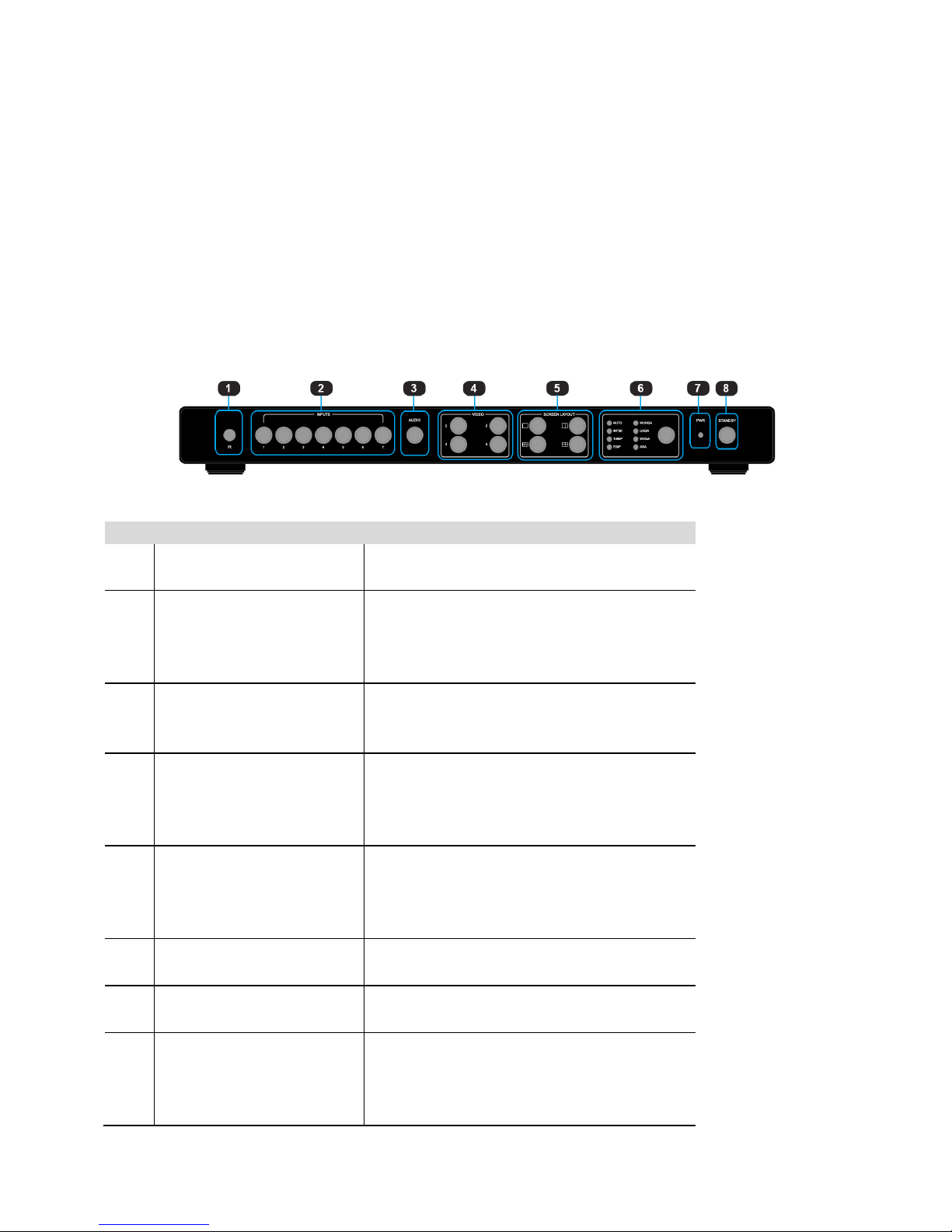
Front Panel
ID
Name
Description
1
IR receive window
IR receive sensor, receives the IR signals
from the IR remote.
2
Input Buttons and Indicator
Presses the buttons 1~7 to select the
corresponding video or audio input. The
indicators mean the corresponding status of
the video or audio input.
3
Audio Selection Button and
Indicator
Presses this button, then the indicator lights
up, meaning switching between audio
outputs.
4
Video Input Button and
Indicator
Presses the buttons 1~4, indicating the
corresponding windows are selected. The
indicators mean whether this window is
effective.
5
Video Window Mode
Button and Indicator
Video window mode selection: single
window, double windows, triple windows
and quadruple windows. The indicators
mean whether this window is effective.
6
Output Resolution Button
and Indicator
Selects the related resolutions, then the
indicators light up.
7
Power Indicator
Indicates whether the power is working
properly or not.
8
Standby button and
indicator
l Switches between standby and normal
work modes.
l When this device is switched to the
standby mode, the indicator lights up.
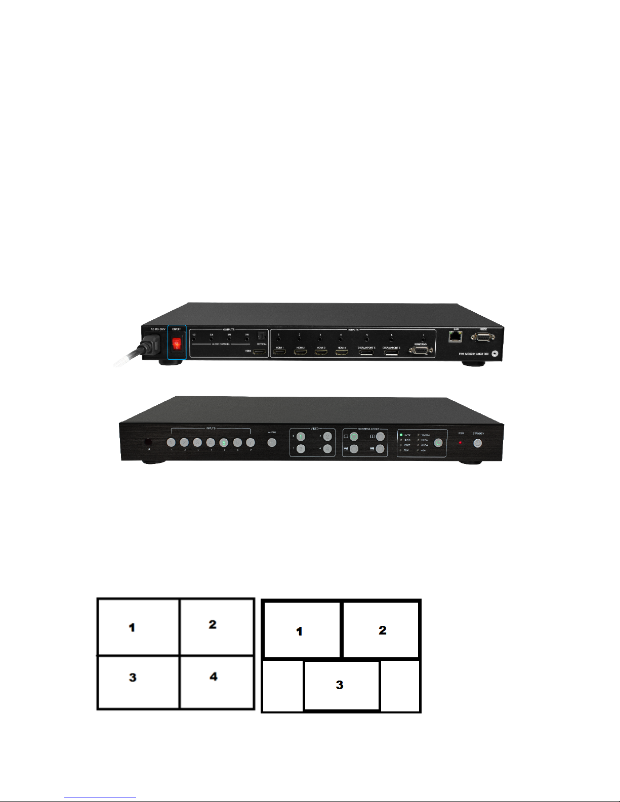
Page 8
8 / 49
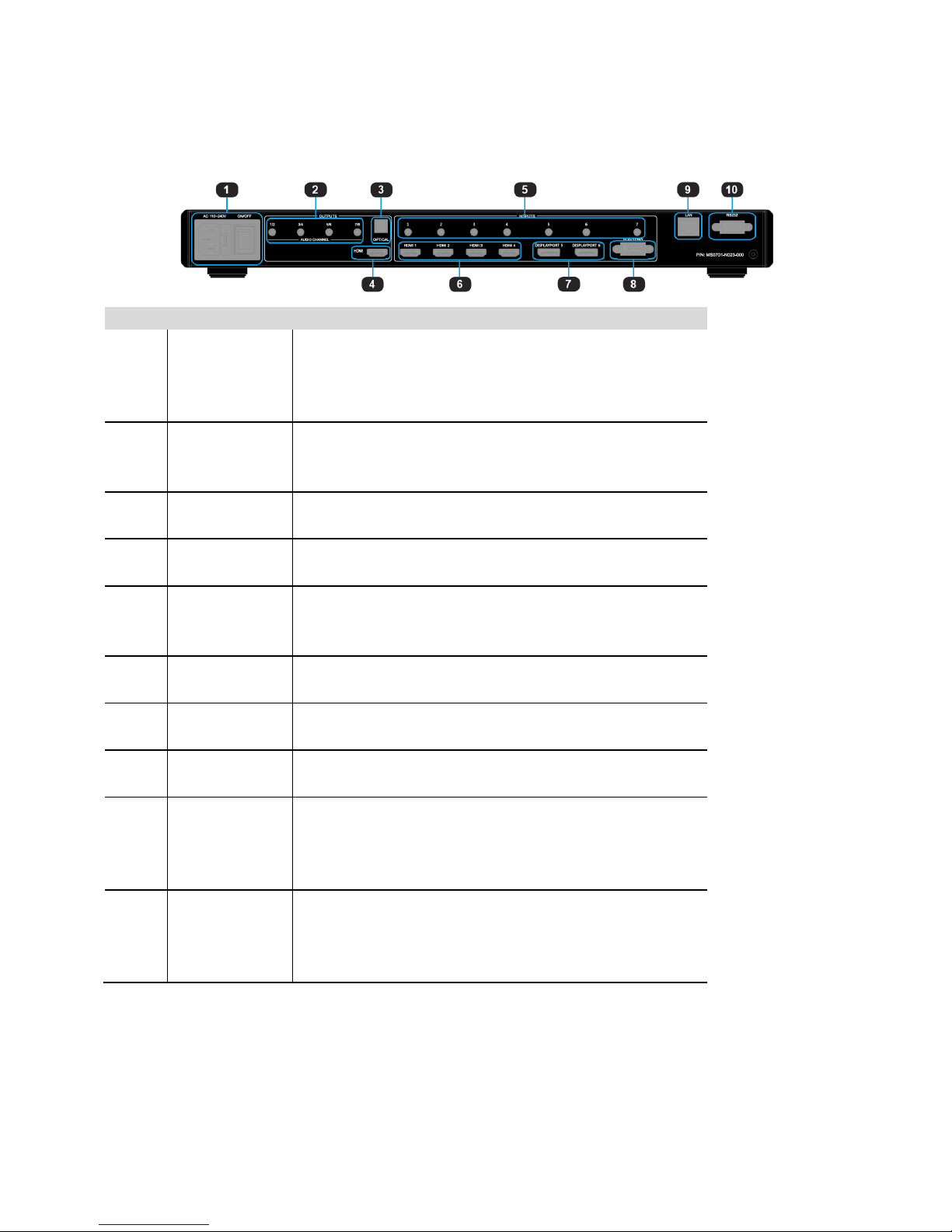
Back Panel
ID
Name
Description
1
Power Switch
and 110/220
AC Power
Receptacle
Turn the power ON or OFF using this switch, Connect
the included AC power cord to this receptacle and
connect the plug to an available electrical outlet.
2
Analog audio
output
8 channel analog audio output, Connect a 3.5mm
mini-stereo cable from this jack to the Line In jack of a
multimedia system.
3
Optical output
Connect the optical output port to the digital audio input
port of your amplifier
4
HDMI output
Connect an HDMI cable from this port to an
HD or 4K display.
5
Analog audio
input 1~7
7 channel stereo analog audio input, Connect a 3.5mm
mini-stereo cable from the Line Out jack on the audio
source to this jack.
6
HDMI input 1~
4
Connect up to four Hi-Def sources to these inputs using
HDMI cables.
7
DisplayPort
input 1~2
Connect up to two Hi-Def sources to these inputs using
DisplayPort cables.
8
RGB/YPbPr
input
Connect up to a Hi-Def sources to this input using
DB-15 cable or YPbPr-VGA cable.
9
IP Cont.
Connect an Ethernet cable between
this jack and a LAN to use IP control.
Refer to RS-232 and IP Configuration for
more information on setting up IP control.
10
RS-232
Connect an RS-232 cable from this port
to an RS-232 device. See RS-232 and
IP Configuration for more information on
setting up RS-232 control.
Page 9
9 / 49
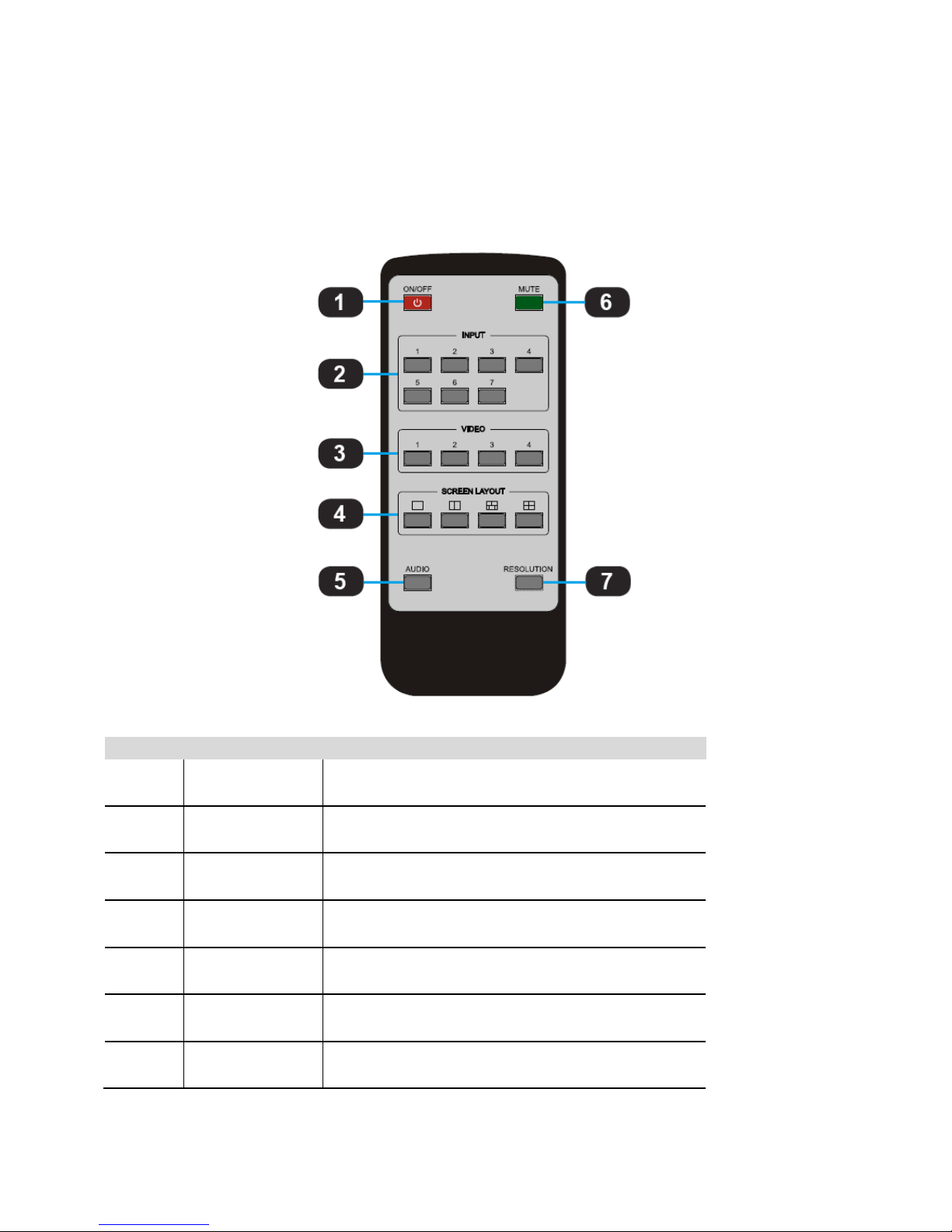
IR Remote Control Unit
Button layout
ID
Name
Description
1
Power
Press this button to power-ON or power-OFF
the Multiviewer Switcher
2
Input 1-7
Press "1-7" buttons to select the corresponding
video input or audio input
3
Windows 1-4
Press "1-7" buttons to select the corresponding
window for select video input
4
Screen Layout
Press this buttons to select Single mode, Double
mode, TRIPLE mode and Quadruple mode
5
Audio
Press this button and then press the "1-7" buttons
to select the corresponding audio input
6
Mute
Press this button to Mute or UnMute the Multiviewer
Switcher audio output
7
Resolution
Press this button to change the Multiviewer
Switcher HDMI output resolution
Page 10
10 / 49
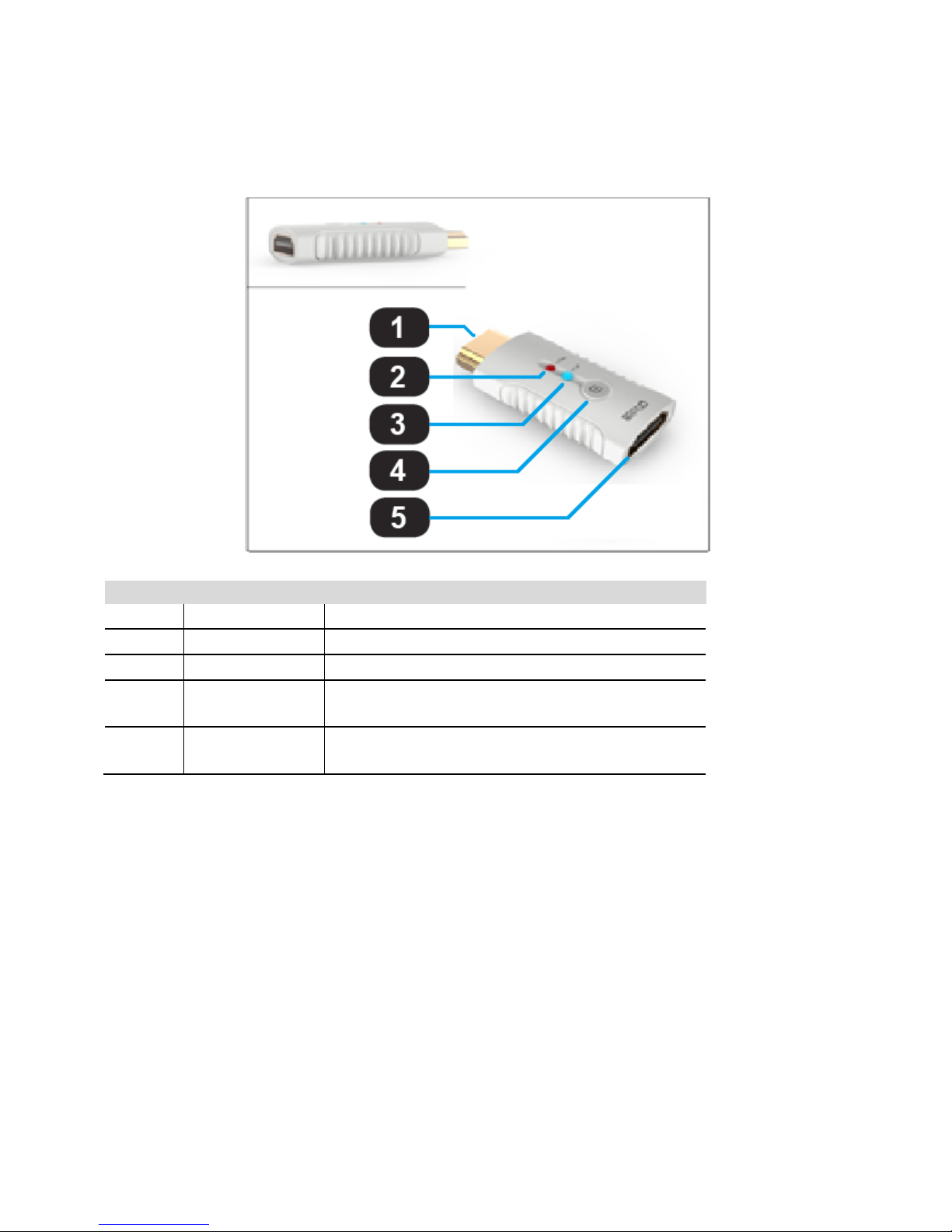
HDMI/DP Cable Switcher (Optional)
ID
Name
Description
1
HDMI/DP Output
Connect up to 4k or Hi-Def HDMI/DP sources
2
Power Indicator
Indicates the power indicator.
3
Link Indicator
Indicates the connection status indicator.
4
Switch Button
Presses this button Multiviewer Switcher to switch
to this signal port.
5
HDMI/DP Input
Connects to the HDMI or DisplayPort ports of
Multiviewer Switcher using the HDMI cables.
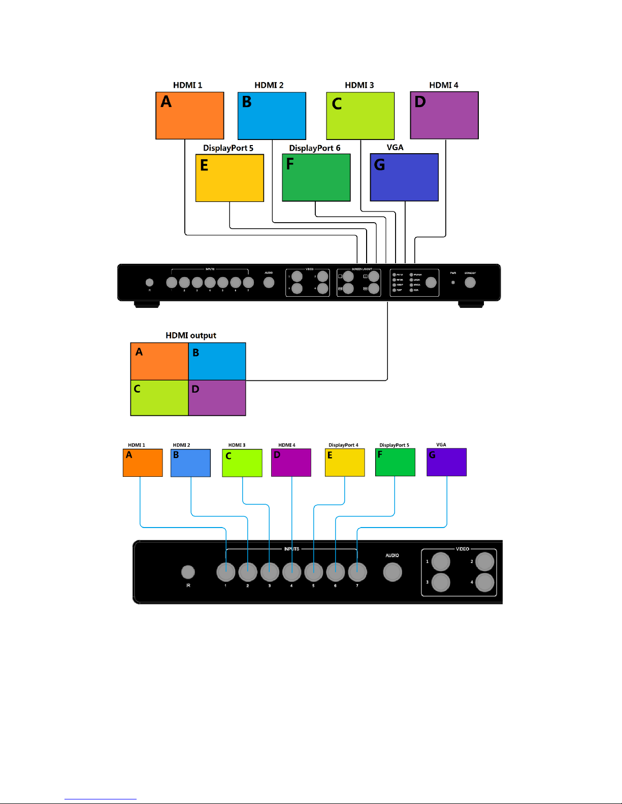
Installation
How to Connect the Multiviewer Switcher
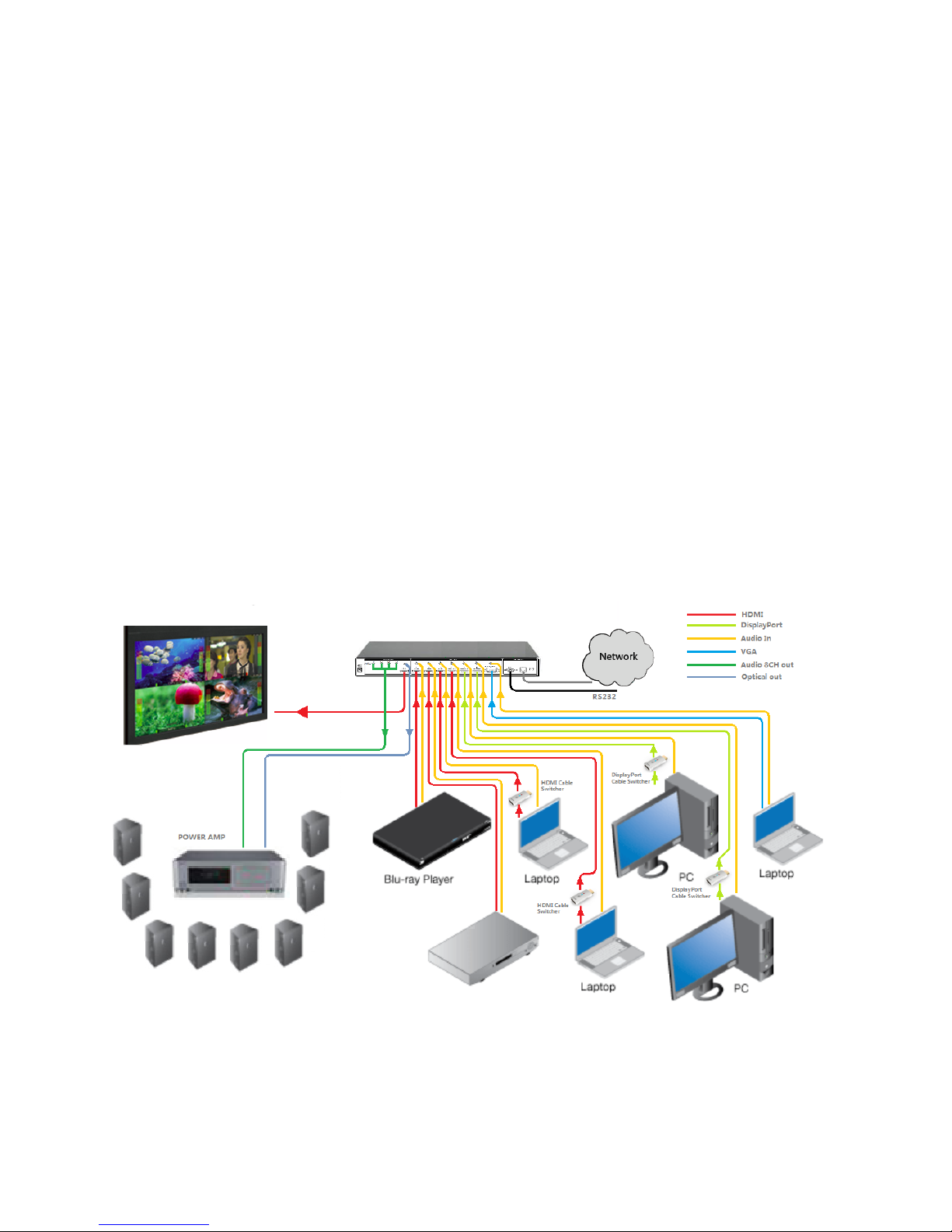
1. Connect up to four 4K or HD HDMI sources to the input ports (HDMI 1 - HDMI 4), Connect up to two 4K
or HD DisplayPort sources to the input ports (DISPLAYPORT 5 - DISPLAYPORT 6), Connect up to one
Hi-Def VGA or YPbPr sources to the input ports (RGB/YPbPr) on the Multiviewer Switcher
2. Connect an 4K or HD display to the HDMI Output port on the Multiviewer Switcher
3. OPTIONAL: Connect up seven stereo analog audio sources to audio input ports(1-7) on the Multiviewer
Switcher.
Page 11
11 / 49
4. OPTIONAL: Connect the HDMI/DP input port of HDMI/DP cable switcher to the 4K or HD source device.
Connect the HDMI/DP input port of Multiviewer Switcher to the HDMI/DP output port of HDMI/DP cable
switcher using HDMI or DP cables.
5. OPTIONAL: Connect four 3.5mm mini-stereo cables from the jacks on the Multiviewer Switcher to the
“Line In” jack of a multimedia system, or connect an optical cable from the OPTICAL on the Multiviewer
Switcher to the “Optical In” of a multimedia system.
6. OPTIONAL: Connect an RS-232 cable from the RS-232 port on the Multiviewer Switcher to the RS-232
connector on the serial controller.
7. OPTIONAL: Connect an Ethernet cable from the LAN port on the Multiviewer Switcher to a Local Area
Network (LAN).
8. Connect the AC power cord to the Multiviewer Switcher and connect the plug to an available electrical
outlet.
Wiring Diagram
Page 12
12 / 49
Operating
Standby Mode and Operational Mode
The “PWR” LED next to the Power button on the front panel indicates the power state of the Multiviewer
Switcher. This indicator remains illuminated as long as power is being supplied to the Multiviewer
Switcher. If this indicator does not illuminate, check the connection between the power receptacle on
the Multiviewer Switcher and the AC outlet.
In Standby mode the Standby indicator will light up until the Multiviewer Switcher wakes up. When the
normal work mode is used, the Standby indicator will turn off. There three methods to wake up the
device include the following: pressing the Standby button, pressing the ON/OFF button on the IR
remote or using LAN or RS232 commands.
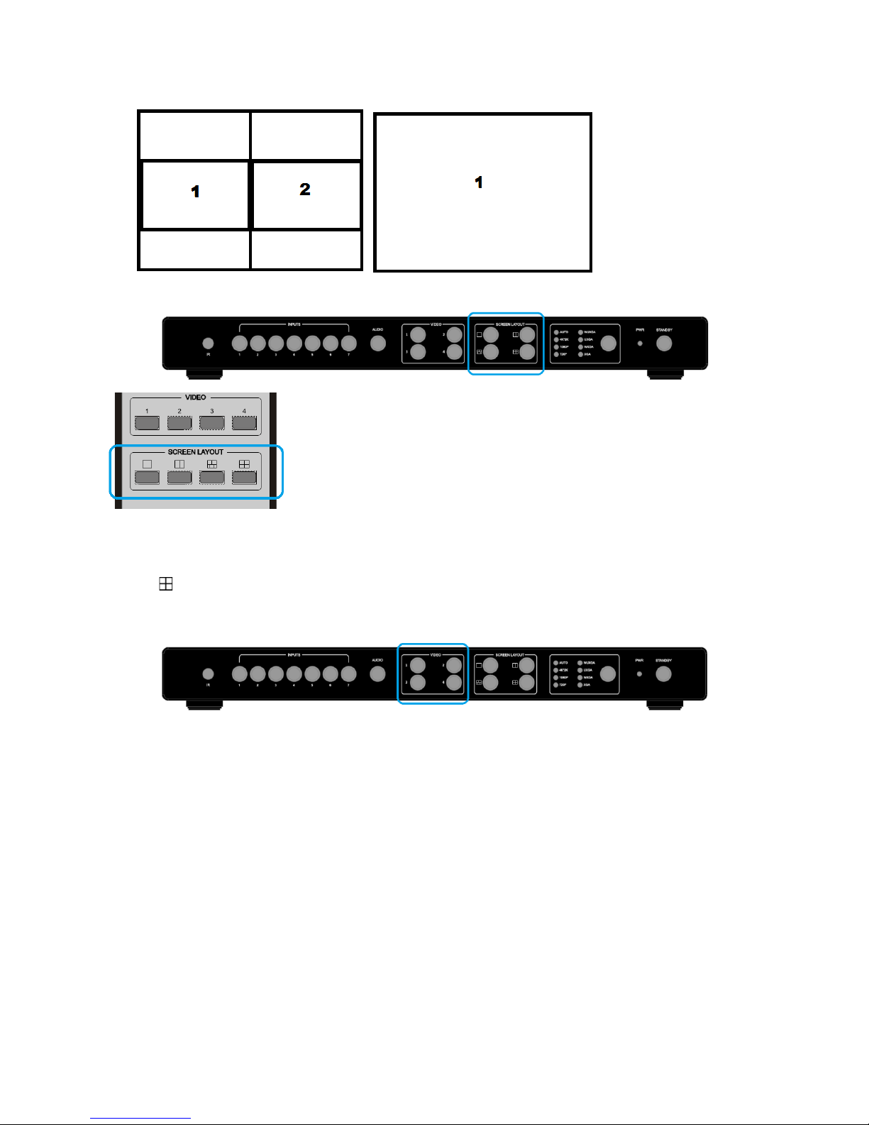
Screen layout Configuration
The Multiviewer Switcher offers four window configurations: quadruple windows, triple windows, double
windows, and single window. The screen configuration is shown as follows.
Page 13
13 / 49
Press the four buttons in the Screen Layout of the Multiviewer Switcher, corresponding to the four
modes above. For example, if you want to use the mode for quadruple windows, press the button so
that the icon is displayed or the button in the remote. The button indicator on the panel will light up,
and the picture output on the display device through HDMI will show quadruple windows. Meanwhile,
the video 1-4 indicators will light up.
The Multiviewer Switcher can display up to four sources. When multiple sources are displayed on the
screen, each source is regarded as a single window, and each window is defined as an input. However,
we want to define the operation in the single window to introduce the basic operation before
introduction to the operation in multiple windows. In the following example, seven HD sources (each
displayed as a single picture) are connected to Multiviewer Switcher. When the Multiviewer Switcher is
delivered from the factory, the default boot settings are loaded automatically (see below).
Page 14
14 / 49
Page 15
15 / 49
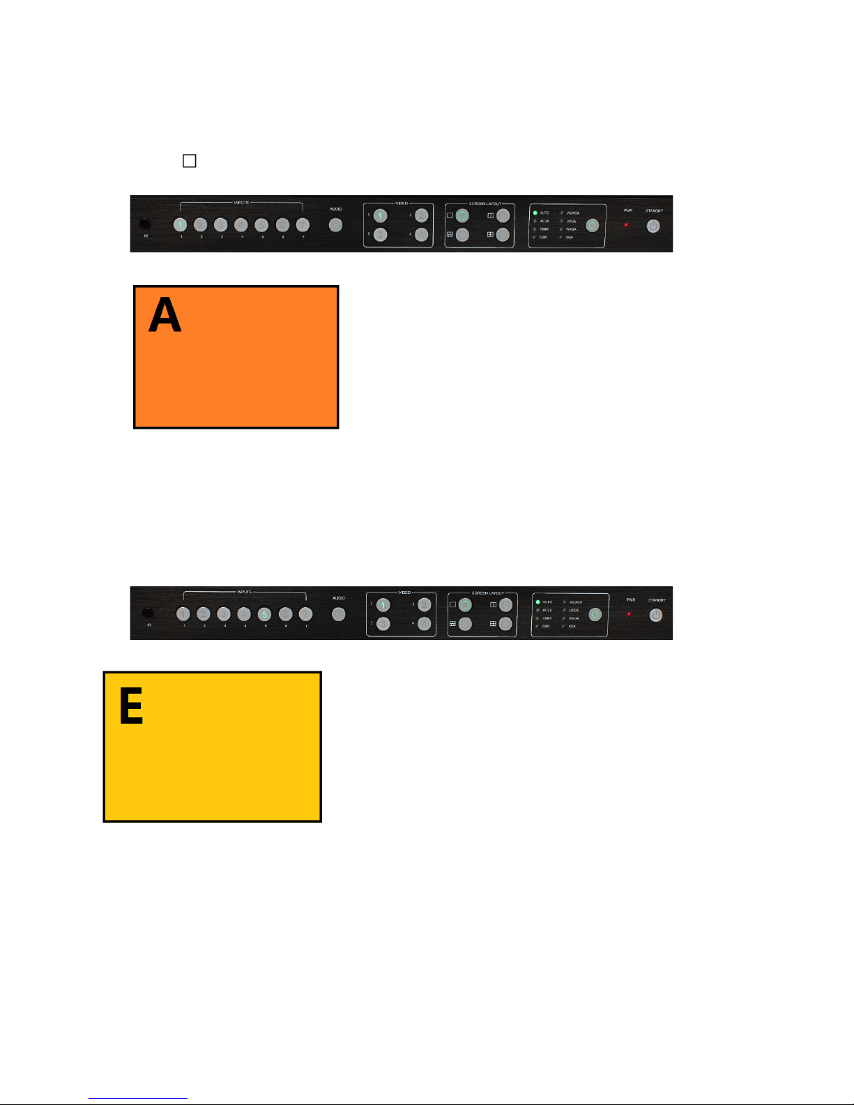
Single Window
1) Use the button on the front panel remote to set to the single window mode. When the Video 1
button indicator lights up, the Input 1 indicator will light up.
2) The HDMI output configures the HDMI 1 input. The window is shown as follows:
3) If you want to switch to the signal of DisplayPort5:
Method 1: Press the INPUTS 5 button on the front panel or remote.
Method 2: Press the Video 1 button on the front panel or remote.
The 1 button indicator on the panel will turn solid and the 2~7 button indicators will blink. If an
indicator is solid, it means that the source is currently selected. If an indicator is blinking, it means
that the source which can be selected.
4) When the 5 button indicator lights up, the panel status is shown as follows:
5) The HDMI output picture is changed to the signal of DisplayPort5.
! '
Page 16

16 / 49
Double Windows
1) Use the “ ” button on the front panel or remote to set the mode to double windows. This will turn
the Video 1 and 2 indicators on the front panel on.
2) The HDMI output port outputs the mode of double
windows. Window 1 is configured to the HDMI 1 input
(HDMI1 is the factory default. If any changes are made,
use the last configuration). Window 2 is configured to
HDMI2 input (HDMI2 is the factory default. If any
changes are made, use the last configuration). The
windows are shown as follows:
3) For example, if you want to switch to Window 1 the signal of DisplayPort5:
Method 1: Press the INPUTS 5 button on the front panel or remote. The Video 1 and 2 button
indicators will blink (this indicates that the two buttons can be selected). Press the Video 1 button on
the front panel or remote to select Window 1.
Method 2: First press the Video 1 button on the front
panel or remote. The 1 button indicator on the panel
will become solid. If the 2~7 button indicators are
blinking (If an indicator is solid on, it means the
source currently selected; If an indicator is blinking, it
means this source can be selected), press the
INPUTS 1 button on the front panel or in the remote.
4) Windows 2 can select DisplayPort6 using the same
method.
5) When the INPUTS indicators are off, the panel status is shown as follows:
6) The HDMI output picture is changed to the status below.
Page 17

17 / 49
Triple Windows
1) Use the “ ” button on the front panel or remote to set to the mode of triple windows. The Video 1, 2,
and 3 button indicators on the front panel will light up.
2) The HDMI output port outputs the mode of triple windows.
Window 1 is configured to HDMI1 input (HDMI1 is the
factory default. If any changes are made, use the last
configuration); Window 2 is configured to HDMI2 input
(HDMI2 is the factory default. If any changes are made,
use the last configuration). Window 3 is configured to
HDMI3 input (HDMI3 is the factory default. If any changes
are made, use the last configuration). The windows are
shown as follows:
3) If you want to switch to Window 1 and the DisplayPort5
signal:
Method 1: Press the INPUTS 5 button on the front panel
or remote. The Video 1 and 2 button indicators blink
(indicates the two buttons can be selected), press the
Video 1 button on the front panel or in the remote to
select Window 1.
Method 2: Press the Video 1 button on the front panel
or remote. The 1 button indicator on the panel turns solid on,
2~7 button indicators will blink (If an indicator is solid, it means the source currently selected. If an
indicator is blinking, it means this source can be selected), press the INPUTS 1 button on the front
panel or in the remote.
4) Using the same methods, Window 2 can select DisplayPort6 and Window 3 can select RGB/YPbPr.
5) When the INPUTS indicators are off, the panel status is shown as follows:
6) The HDMI output picture is changed to the following status.
Page 18

18 / 49
Quadruple Windows
1) Use the “ ” button on the front panel or remote to set to the mode of quadruple windows. The
Video 1, 2, 3, and 4 button indicators on the front panel will light up.
2) HDMI output port outputs the mode of quadruple windows. Window 1 is configured to HDMI1 input
(HDMI1 is the factory default. If any changes are made,
use the last configuration); Window 2 is configured to
HDMI2 input (HDMI2 is the factory default. If any changes
are made, use the last configuration); Window 3 is
configured to HDMI3 input (HDMI3 is the factory default. If
any changes are made, use the last configuration);
Window 4 is configured to HDMI4 input (HDMI4 is the
factory default. If any changes are made, use the last
configuration). The windows are shown as follows:
3) If you want to switch to Window 1 switch the signal of DisplayPort5, use one of the following
methods:
Method 1: Press the INPUTS 5 button on the front panel or
remote, the Video 1 and 2 button indicators blink (indicates the
two buttons can be selected), press the Video 1 button on the
front panel or in the remote to select Window 1.
Method 2: Press the Video 1 button on the front panel or
remote, the 1 button indicator on the panel turns solid, 2~7 button
indicators are blinking (If an indicator is solid on, it means the source
currently selected; If an indicator is blinking, it means this source can be selected), press the INPUTS 1
button on the front panel or in the remote.
4) In the same methods, Window 2 can select DisplayPort6, and Window 3 can select RGB/YPbPr.
5) When the INPUTS indicators are off, the panel status is shown as follows.
6) HDMI output picture is changed to the following status.
Page 19

19 / 49
Output Resolution
HDMI output resolutions support multiple modes with the indicator indication.
• Auto'
• 4K'*'2K' ' (3840'*'2160'@30Hz)'
• 1080P' ' ' ' (1920'*'1080'@'60Hz)'
• 720P' ' ('1280'*'720'@'60Hz)'
• WUXGA'(1900'*'1200'@'60Hz)'
• UXGA'(1600'*'1200'@'60HZ)'
• WXGA'(1280'*'800'@'60Hz)'
• XGA'(1024'*'768'@60Hz)'
'
Auto means that the output of the HDMI resolutions is based on the EDID information read from the
display device.
Operation method:
Press the Resolution buttons on the panel or remote to switch between different HDMI output
resolutions. The switching sequence is as follows: Auto -> 4K x 2K -> 1080P -> 720P -> WUXGA ->
UXGA -> WXGA -> XGA -> Auto. When a resolution is selected, the corresponding indicator lights up
and the HDMI output is switched to the new resolution.
Audio Setting
The MV71 supports breakaway audio and requires the audio to be selected separately from the video.
Audio Input Select
The audio also has seven inputs. When the video input is selected as HDMI or DisplayPort, the audio
will input from HDMI or DP. If the HDMI or DP input has no audio, the audio input will come from the
corresponding 3.5 mm earphone jack. For example, if the DVI signal is transmitted through HDMI1, the
audio will input from the 3.5mm earphone jack of the audio output 1 (above the HDMI1 port). VGA video
corresponds to the 3.5mm jack of the audio output 7.
Page 20

20 / 49
Operations for audio switching:
Method 1:
(1). Press audio button. The corresponding indicator will light up. This means that the audio output is
selected. If the Input indicator of the corresponding audio source turns solid, the other indicators will
blink.
(2). Press the Inputs button. The audio will switch to this channel. At the same time the Input indicators
and audio indicator are off.
(3).) If no further operation is performed within 5 seconds during Step 2, it will exit from this status.
Method 2:
(1). Press the audio button. The corresponding indicator will light up, which means that the audio
output is selected. When the Input indicator of the corresponding audio source turns solid, the other
indicators blink.
(2). Press the desired “Inputs” button and the audio will switch to this channel. At the same time, the
Input indicators and audio indicator will turn off.
(3). If no further operation is performed within 5 seconds during Step 2, it will exit from this status.
Notes:
(1). Press the audio button and the “Inputs” indicator of the corresponding audio source will become
solid while the other indicators blink. This will confirm the current audio selected channel.
(2). HDMI and DisplayPort have a 3.5mm stereo audio jack. If HDMI or DisplayPort input
signals have audio format, then the digital audio signal is used. If these signals are without audio
format, then it will automatically switch to the 3.5mm analog input.
Page 21

21 / 49
Audio
Format
Channel
1 2 3 4 5 6 7 8 2.0 L R
2.1 L R
LFE
5.1
FL
FR
LFE
FC
RL
RR
7.1
FL
FR
LFE
FC
RL
RR
RLC
RRC
Audio Output Instructions
There are three methods of audio output:
(1). HDMI output
(2). Optical output
(3). Analog output, 8 channels for audio output
If the input audio format is stereo, then “½” audio output is used. If the audio format is 5.1, then
channels from 1 to 6 output the audio.
OSD Setting Instructions
The On Screen Display (OSD) will show when inputs or volume levels are changed. These ODS
images can be turned off using control commands.
1) Boot logo
2) Each window displays an input source, the resolution of the input signal, whether or not there is
no HDMI cable, no HDMI signal, or no HDMI/DisplayPort/VGA.
A. Single window:
B. Double windows:
Page 22

22 / 49
C. When the triple windows are displayed:
Page 23

23 / 49
D. Quad windows:
3) Audio Mute indicates:
4) Volume adjustment:
5) VGA Auto Menu:
Page 24

24 / 49
6) IP address:
Page 25

25 / 49
Advanced Settings
RS232 Setting
RS-232 port:
Connect to RXD, TXD, GND only
RS-232 Settings:
Description
Setting
Baud rate
9600
Data bits
8
Parity
None
Stop bits
1
Hardware flow control
None
Notes: For more information about serial command lines, see the chapter of commands.
Page 26

26 / 49
IP Setting
MV71 supports IP control, Telnet, UTP, and so on. There are two methods to obtaining the IP address:
1. Obtain the IP address and port number via the information from the on-screen display (OSD).
2. Obtain the IP address and port number via SmartGui.
The following presents the two methods:
Obtain the IP address and port number via the information from the OSD.
Whether MV71 is in single-window mode or in multiple window mode, IP address and port number can
always be obtained from Window 1. When there is no signal, the following OSD in the window is
displayed:
When the picture is displayed, the IP information is displayed in the area above the middle of the
window.
In this example, the IP address is 192.168.1.1 and the port number is 23.
Obtain the IP address and port number via SmartGui.
Start SmartGUI on the PC. The software interface is shown as follows.
Page 27

27 / 49
Make sure that the PC and MV71 are in the same network segment. Click Search. The following device
list is shown:
Select the device, and click Setup. The IP information is obtained from the Device Info page: IP:
192.168.3.7 Port:23
Page 28

28 / 49
Command List
The MV71 is controlled or operated through the commands from RS232 or IP. The command contains
the following:
• Source Control
• Advanced Control
• EDID Management
Command header: ATM
Length: <=255
Command: xxxxxxx
Read/Write: W/R
Parameter data : xx (N byte) Carriage Return Termination is not required. All values are in ASCII.
Page 29

29 / 49
Source Control
Function
Item
Command
Description
Screen
Layout:
Single Viewer
ATM 09 SCR_LYT W 1
Switch to the single window.
Double Viewer
ATM 09 SCR_LYT W 2
Switch to the double windows.
Triple Viewer
ATM 09 SCR_LYT W 3
Switch to the triple windows.
Quadruple
Viewer
ATM 09 SCR_LYT W 4
Switch to the quadruple windows.
Video Input Select by Viewer
Viewer 1:
Select input #1
ATM 0A VDO_IPT W 1 1
Video input of Window 1 is set to 1.
Select input #2
ATM 0A VDO_IPT W 1 2
Video input of Window 1 is set to 2.
Select input #3
ATM 0A VDO_IPT W 1 3
Video input of Window 1 is set to 3.
Select input #4
ATM 0A VDO_IPT W 1 4
Video input of Window 1 is set to 4.
Select input #5
ATM 0A VDO_IPT W 1 5
Video input of Window 1 is set to 5.
Select input #6
ATM 0A VDO_IPT W 1 6
Video input of Window 1 is set to 6.
Select input #7
ATM 0A VDO_IPT W 1 7
Video input of Window 1 is set to 7.
Viewer 2:
Select input #1
ATM 0A VDO_IPT W 2 1
Video input of Window 2 is set to 1.
Select input #2
ATM 0A VDO_IPT W 2 2
Video input of Window 2 is set to 2.
Select input #3
ATM 0A VDO_IPT W 2 3
Video input of Window 2 is set to 3.
Select input #4
ATM 0A VDO_IPT W 2 4
Video input of Window 2 is set to 4.
Select input #5
ATM 0A VDO_IPT W 2 5
Video input of Window 2 is set to 5.
Select input #6
ATM 0A VDO_IPT W 2 6
Video input of Window 2 is set to 6.
Select input #7
ATM 0A VDO_IPT W 2 7
Video input of Window 2 is set to 7.
Viewer 3:
Select input #1
ATM 0A VDO_IPT W 3 1
Video input of Window 3 is set to 1.
Select input #2
ATM 0A VDO_IPT W 3 2
Video input of Window 3 is set to 2.
Select input #3
ATM 0A VDO_IPT W 3 3
Video input of Window 3 is set to 3.
Select input #4
ATM 0A VDO_IPT W 3 4
Video input of Window 3 is set to 4.
Select input #5
ATM 0A VDO_IPT W 3 5
Video input of Window 3 is set to 5.
Select input #6
ATM 0A VDO_IPT W 3 6
Video input of Window 3 is set to 6.
Select input #7
ATM 0A VDO_IPT W 3 7
Video input of Window 3 is set to 7.
Viewer 4:
Select input #1
ATM 0A VDO_IPT W 4 1
Video input of Window 4 is set to 1.
Select input #2
ATM 0A VDO_IPT W 4 2
Video input of Window 4 is set to 2.
Select input #3
ATM 0A VDO_IPT W 4 3
Video input of Window 4 is set to 3.
Select input #4
ATM 0A VDO_IPT W 4 4
Video input of Window 4 is set to 4.
Select input #5
ATM 0A VDO_IPT W 4 5
Video input of Window 4 is set to 5.
Select input #6
ATM 0A VDO_IPT W 4 6
Video input of Window 4 is set to 6.
Select input #7
ATM 0A VDO_IPT W 4 7
Video input of Window 4 is set to 7.
Page 30

30 / 49
Audio Source Selection
Audio input
select:
Select input #1
ATM 09 ADO_IPT W 1
Audio output is set to audio input 1
Select input #2
ATM 09 ADO_IPT W 2
Audio output is set to audio input 2
Select input #3
ATM 09 ADO_IPT W 3
Audio output is set to audio input 3
Select input #4
ATM 09 ADO_IPT W 4
Audio output is set to audio input 4
Select input #5
ATM 09 ADO_IPT W 5
Audio output is set to audio input 5
Select input #6
ATM 09 ADO_IPT W 6
Audio output is set to audio input 6
Select input #7
ATM 09 ADO_IPT W 7
Audio output is set to audio input 7
Audio Input
Config:
Select ext. audio
on input #1
ATM 0A AUD_MOD W 1 1
ATM 0A AUD_MOD W M N
M: input number; N: 0/1, 0-HDMI auto
audio, 1-external audio
E.g. This item is “Set external audio on
input No. 1”
Select ext. audio
on input #2
ATM 0A AUD_MOD W 2 1
Set external audio on input No. 2
Select ext. audio
on input #3
ATM 0A AUD_MOD W 3 1
Set external audio on input No. 3
Select ext. audio
on input #4
ATM 0A AUD_MOD W 4 1
Set external audio on input No. 4
Select ext. audio
on input #5
ATM 0A AUD_MOD W 5 1
Set external audio on input No. 5
Select ext. audio
on input #6
ATM 0A AUD_MOD W 6 1
Set external audio on input No. 6
Get Audio
Input
Conifg
State:
Check audio set
on input #1
ATM 09 AUD_MOD R 1
ATM 09 AUD_MOD R M
M: input number; N: 0/1, 0-HDMI auto
audio, 1-external audio
E.g. This item is “Check audio input
configuration set on input No. 1”
Check audio set
on input #2
ATM 09 AUD_MOD R 2
Check audio input configuration set on
input No. 2
Check audio set
on input #3
ATM 09 AUD_MOD R 3
Check audio input configuration set on
input No. 3
Check audio set
on input #4
ATM 09 AUD_MOD R 4
Check audio input configuration set on
input No. 4
Check audio set
on input #5
ATM 09 AUD_MOD R 5
Check audio input configuration set on
input No. 5
Check audio set
on input #6
ATM 09 AUD_MOD R 6
Check audio input configuration set on
input No. 6
Page 31

31 / 49
Volume Control
Audio
volume
control:
Volume = 0 - 10
ATM 09 VOL_CRL W [X]
[X] = 0 To 10, 0 = Off
Audio
Mute:
Set audio mute “ON”
ATM 09 AUD_MUT W 0
Set the audio output as mute
Set audio mute
“OFF”
ATM 09 AUD_MUT W F
Cancel the mute setting for the audio
output
Aspect Ratio Selection
viewer 1:
NORMAL
ATM 0A WIN_RAT W 1 1
Set the picture in Window 1 as the
original aspect ratio
FULL
ATM 0A WIN_RAT W 1 2
Set the picture in Window 1 to fill the
entire window
16:9
ATM 0A WIN_RAT W 1 3
Set the picture in Window 1 as the 16:9
aspect ratio
4:3
ATM 0A WIN_RAT W 1 4
Set the picture in Window 1 as the 4:3
aspect ratio
viewer 2:
NORMAL
ATM 0A WIN_RAT W 2 1
Set the picture in Window 2 as the
original aspect ratio
FULL
ATM 0A WIN_RAT W 2 2
Set the picture in Window 2 to fill the
entire window
16:9
ATM 0A WIN_RAT W 2 3
Set the picture in Window 2 as the 16:9
aspect ratio
4:3
ATM 0A WIN_RAT W 2 4
Set the picture in Window 2 as the 4:3
aspect ratio
viewer 3:
NORMAL
ATM 0A WIN_RAT W 3 1
Set the picture in Window 3 as the
original aspect ratio
FULL
ATM 0A WIN_RAT W 3 2
Set the picture in Window 3 to fill the
entire window
16:9
ATM 0A WIN_RAT W 3 3
Set the picture in Window 3 as the 16:9
aspect ratio
4:3
ATM 0A WIN_RAT W 3 4
Set the picture in Window 3 as the 4:3
aspect ratio
viewer 4:
NORMAL
ATM 0A WIN_RAT W 4 1
Set the picture in Window 4 as the
original aspect ratio
FULL
ATM 0A WIN_RAT W 4 2
Set the picture in Window 4 to fill the
entire window
16:9
ATM 0A WIN_RAT W 4 3
Set the picture in Window 4 as the 16:9
aspect ratio
4:3
ATM 0A WIN_RAT W 4 4
Set the picture in Window 4 as the 4:3
aspect ratio
Page 32

32 / 49
Resolution Selection
Output
Timing:
AUTO
ATM 09 OPT_TIM W 1
Set the HDMI output as AUTO,
outputting the resolutions based on
the EDID information of the display
device.
4Kx2K@30Hz UHD
ATM 09 OPT_TIM W 2
Sets the HDMI output resolution as
4Kx2K@30Hz UHD
1920X1080@60Hz
1080P FHD
ATM 09 OPT_TIM W 3
Sets the HDMI output resolution as
1920X1080@60Hz 1080P FHD
1280X720@60Hz
720P
ATM 09 OPT_TIM W 4
Sets the HDMI output resolution as
1280X720@60Hz 720P
1920X1200@60Hz
WUXGA
ATM 09 OPT_TIM W 5
Sets the HDMI output resolution as
1920X1200@60Hz WUXGA
1600X1200@60Hz
UXGA
ATM 09 OPT_TIM W 6
Sets the HDMI output resolution as
1600X1200@60Hz UXGA
1280X800@60Hz
WXGA
ATM 09 OPT_TIM W 7
Sets the HDMI output resolution as
1280X800@60Hz WXGA
1024X768@60Hz
XGA
ATM 09 OPT_TIM W 8
Sets the HDMI output resolution as
1024X768@60Hz XGA
Advanced Control
Power Control
Function
Item
Command
Description
Power
control:
Power On Unit
ATM 09 POW_CRL W 0
Please note number “0” not Letter
“O”
Power Off Unit
ATM 09 POW_CRL W F
Set unit to stand by.
Power
saving
Disabled
ATM 0A POW_SAV W 00
Set Power Saving disable
5 Minutes
ATM 0A POW_SAV W 05
Set the duration time as 5 minutes.
10 Minutes
ATM 0A POW_SAV W 0A
Set the duration time to 10
minutes.
15 Minutes
ATM 0A POW_SAV W 0F
Set the duration time to 15
minutes.
30 Minutes
ATM 0A POW_SAV W 1E
Set the duration time to 30
minutes.
60 Minutes
ATM 0A POW_SAV W 3C
Set the duration time to 60
minutes.
Page 33

33 / 49
Audio Delay
System Controls
Audio
delay:
Off
ATM 09 AUD_DLY W 0
Set the audio output delay to Off.
40ms
ATM 09 AUD_DLY W 1
Set the audio output delay (40ms)
80ms
ATM 09 AUD_DLY W 2
Set the audio output delay (80ms)
120ms
ATM 09 AUD_DLY W 3
Set the audio output delay (120ms)
160ms
ATM 09 AUD_DLY W 4
Set the audio output delay (160ms)
200ms
ATM 09 AUD_DLY W 5
Set the audio output delay (200ms)
240ms
ATM 09 AUD_DLY W 6
Set the audio output delay (240ms)
280ms
ATM 09 AUD_DLY W 7
Set the audio output delay (300ms)
320ms
ATM 09 AUD_DLY W 8
Set the audio output delay (340ms)
360ms
ATM 09 AUD_DLY W 9
Set the audio output delay (380ms)
400ms
ATM 09 AUD_DLY W A
Set the audio output delay (400ms)
VGA input
Auto
Position:
AUTO-adjust on
VGA input
ATM 08 VGA_AUT W
When it's VGA, it adjusts image
position automatically.
OSD
control:
Audio OSD on/off
ATM 09 AUD_OSD W 0
Turn on/off the audio volume and
mute OSD.
0: audio OSD on; 1: audio OSD off
Video OSD on/off
ATM 09 VDO_OSD W 0
Turn on/off the video source and IP
address OSD.
0: video OSD on, 1: video OSD off
HDMI
output
audio
control
HDMI Output audio
Mute / Unmute
ATM 09 AUD_OPT W 1
Mute/Unmute HDMI embedded
audio.
0: Mute, 1: Unmute
Restore
Default
Setting
Restore unit to
default factory set
CMD 0C RST_SET W
Reset to factory default settings.
Set Baud
Rate:
9600
ATM 09 BAU_RAT W 1
Set the window baud rate as 9600
14400
ATM 09 BAU_RAT W 2
Set the window baud rate as 14400
19200
ATM 09 BAU_RAT W 3
Set the window baud rate as 19200
38400
ATM 09 BAU_RAT W 4
Set the window baud rate as 38400
56000
ATM 09 BAU_RAT W 5
Set the window baud rate as 56000
57600
ATM 09 BAU_RAT W 6
Set the window baud rate as 57600
115200
ATM 09 BAU_RAT W 7
Set the window baud rate as
115200
Page 34

34 / 49
HDCP
Timing
output
Read
EDID:
Enable HDCP on
HDMI output
ATM 0A HDO_HDP W 1
0
Enable the HDCP “Switch-ON” on
the HDMI output port
Disable HDCP on
HDMI output
ATM 0A HDO_HDP W 1
F
Disable the HDCP “Switch-ON” on
the HDMI output port
Enable HDCP on
HDBase-T output
ATM 0A HDO_HDP W 2
0
Enable the HDCP “Switch-ON” on
the HDBase-T output port
Disable HDCP on
HDBase-T output
ATM 0A HDO_HDP W 2
F
Disable the HDCP “Switch-ON” on
the HDBase-T output port
Check HDCP status
on HDMI output
ATM 08 HDO_HDP R
Read/Check the HDCP switch
status on the HDMI output port
Check the HDMI
output timing
ATM 09 HDO_EDI W 1
Read/Check the timing of HDMI
output port
Check the HDBT
output timing
ATM 09 HDO_EDI W 2
Read/Check the timing of
HDBase-T output port
Others
Get SW Version:
ATM 08 CSW_VER W
Read/Check the software version
enable input HDCP
KEY
ATM 09 IPT_DCP W 1
Enable the HDMI input HDCP
“Switch-ON”
Set input HDMI/DP
embedded audio to
“MUTE”
ATM 09 AUD_OPT W 1
Set the HDMI/DP embedded audio
to “MUTE”
Activate system
update by USB disk
ATM 09 SYS_UPT W 1
Start the upgrading progress
through USB connected with
upgrading file stored inside
Page 35

35 / 49
EDID Management
The MV71 has EDID management capabilities where either simple EDID presets can be recalled for or
EDID data can be captured or loaded into ROM and copied to each input. The simplest method is to
use the built in preset EDIDs and assign them to an input.
Example:
Assign preset EDID to input port:
Send: ATM 0B EDI_POR W M C N
M: = 1, 2, 3, 4, 5, 6, 7 (Input port No. 1-7)
N: = 1, 2, 3, 4, 5, 6 (Select preset EDID No.1-6)
Feedback:EDI_POR
Page 36

36 / 49
Copy Preset EDID
Function
Item
Command
Description
Copy Preset
EDID to Port_1
1
ATM 0B EDI_POR W 1 C 1
Copy the preset EDID 1 in the program to port 1
2
ATM 0B EDI_POR W 1 C 2
Copy the preset EDID 2 in the program to port 1
3
ATM 0B EDI_POR W 1 C 3
Copy the preset EDID 3 in the program to port 1
4
ATM 0B EDI_POR W 1 C 4
Copy the preset EDID 4 in the program to port 1
Copy Preset
EDID to Port_2
1
ATM 0B EDI_POR W 2 C 1
Copy the preset EDID 1 in the program to port 2
2
ATM 0B EDI_POR W 2 C 2
Copy the preset EDID 2 in the program to port 2
3
ATM 0B EDI_POR W 2 C 3
Copy the preset EDID 3 in the program to port 2
4
ATM 0B EDI_POR W 2 C 4
Copy the preset EDID 4 in the program to port 2
Copy Preset
EDID to Port_3
1
ATM 0B EDI_POR W 3 C 1
Copy the preset EDID 1 in the program to port 3
2
ATM 0B EDI_POR W 3 C 2
Copy the preset EDID 2 in the program to port 3
3
ATM 0B EDI_POR W 3 C 3
Copy the preset EDID 3 in the program to port 3
4
ATM 0B EDI_POR W 3 C 4
Copy the preset EDID 4 in the program to port 3
Copy Preset
EDID to Port_4
1
ATM 0B EDI_POR W 4 C 1
Copy the preset EDID 1 in the program to port 4
2
ATM 0B EDI_POR W 4 C 2
Copy the preset EDID 2 in the program to port 4
3
ATM 0B EDI_POR W 4 C 3
Copy the preset EDID 3 in the program to port 4
4
ATM 0B EDI_POR W 4 C 4
Copy the preset EDID 4 in the program to port 4
Copy Preset
EDID to Port_5
1
ATM 0B EDI_POR W 5 C 1
Copy the preset EDID 1 in the program to port 5
2
ATM 0B EDI_POR W 5 C 2
Copy the preset EDID 2 in the program to port 5
3
ATM 0B EDI_POR W 5 C 3
Copy the preset EDID 3 in the program to port 5
4
ATM 0B EDI_POR W 5 C 4
Copy the preset EDID 4 in the program to port 5
5
ATM 0B EDI_POR W 5 C 6
Copy the preset EDID 6 in the program to port 5
Copy Preset
EDID to Port_6
1
ATM 0B EDI_POR W 6 C 1
Copy the preset EDID 1 in the program to port 6
2
ATM 0B EDI_POR W 6 C 2
Copy the preset EDID 2 in the program to port 6
3
ATM 0B EDI_POR W 6 C 3
Copy the preset EDID 3 in the program to port 6
4
ATM 0B EDI_POR W 6 C 4
Copy the preset EDID 4 in the program to port 6
5
ATM 0B EDI_POR W 6 C 6
Copy the preset EDID 6 in the program to port 6
Copy Preset
EDID to Port_7
1
ATM 0B EDI_POR W 7 C 4
Copy the preset EDID 4 in the program to port 7
2
ATM 0B EDI_POR W 7 C 5
Copy the preset EDID 5 in the program to port 7
Page 37

37 / 49
Copy EEPROM EDID
Function
Item
Command
Description
Copy EEPROM
EDID to Port_1
1
ATM 0B EDI_POR W 1 E 1
Copy the EDID of the EEPROM 1 to port 1
2
ATM 0B EDI_POR W 1 E 2
Copy the EDID of the EEPROM 2 to port 1
3
ATM 0B EDI_POR W 1 E 3
Copy the EDID of the EEPROM 3 to port 1
4
ATM 0B EDI_POR W 1 E 4
Copy the EDID of the EEPROM 4 to port 1
5
ATM 0B EDI_POR W 1 E 5
Copy the EDID of the EEPROM 5 to port 1
6
ATM 0B EDI_POR W 1 E 6
Copy the EDID of the EEPROM 6 to port 1
7
ATM 0B EDI_POR W 1 E 7
Copy the EDID of the EEPROM 7 to port 1
Copy EEPROM
EDID to Port_2
1
ATM 0B EDI_POR W 2 E 1
Copy the EDID of the EEPROM 1 to port 2
2
ATM 0B EDI_POR W 2 E 2
Copy the EDID of the EEPROM 2 to port 2
3
ATM 0B EDI_POR W 2 E 3
Copy the EDID of the EEPROM 3 to port 2
4
ATM 0B EDI_POR W 2 E 4
Copy the EDID of the EEPROM 4 to port 2
5
ATM 0B EDI_POR W 2 E 5
Copy the EDID of the EEPROM 5 to port 2
6
ATM 0B EDI_POR W 2 E 6
Copy the EDID of the EEPROM 6 to port 2
7
ATM 0B EDI_POR W 2 E 7
Copy the EDID of the EEPROM 7 to port 2
Copy EEPROM
EDID to Port_3
1
ATM 0B EDI_POR W 3 E 1
Copy the EDID of the EEPROM 1 to port 3
2
ATM 0B EDI_POR W 3 E 2
Copy the EDID of the EEPROM 2 to port 3
3
ATM 0B EDI_POR W 3 E 3
Copy the EDID of the EEPROM 3 to port 3
4
ATM 0B EDI_POR W 3 E 4
Copy the EDID of the EEPROM 4 to port 3
5
ATM 0B EDI_POR W 3 E 5
Copy the EDID of the EEPROM 5 to port 3
6
ATM 0B EDI_POR W 3 E 6
Copy the EDID of the EEPROM 6 to port 3
7
ATM 0B EDI_POR W 3 E 7
Copy the EDID of the EEPROM 7 to port 3
Copy EEPROM
EDID to Port_4
1
ATM 0B EDI_POR W 4 E 1
Copy the EDID in the EEPROM 1 to port 4
2
ATM 0B EDI_POR W 4 E 2
Copy the EDID in the EEPROM 2 to port 4
3
ATM 0B EDI_POR W 4 E 3
Copy the EDID in the EEPROM 3 to port 4
4
ATM 0B EDI_POR W 4 E 4
Copy the EDID in the EEPROM 4 to port 4
5
ATM 0B EDI_POR W 4 E 5
Copy the EDID in the EEPROM 5 to port 4
6
ATM 0B EDI_POR W 4 E 6
Copy the EDID in the EEPROM 6 to port 4
7
ATM 0B EDI_POR W 4 E 7
Copy the EDID in the EEPROM 7 to port 4
Copy EEPROM
EDID to Port_5
1
ATM 0B EDI_POR W 5 E 1
Copy the EDID of the EEPROM 1 to port 5
2
ATM 0B EDI_POR W 5 E 2
Copy the EDID of the EEPROM 2 to port 5
3
ATM 0B EDI_POR W 5 E 3
Copy the EDID of the EEPROM 3 to port 5
4
ATM 0B EDI_POR W 5 E 4
Copy the EDID of the EEPROM 4 to port 5
5
ATM 0B EDI_POR W 5 E 5
Copy the EDID of the EEPROM 5 to port 5
6
ATM 0B EDI_POR W 5 E 6
Copy the EDID of the EEPROM 6 to port 5
7
ATM 0B EDI_POR W 5 E 7
Copy the EDID of the EEPROM 7 to port 5
Page 38

38 / 49
Function
Item
Command
Description
Copy EEPROM
EDID to Port_6
1
ATM 0B EDI_POR W 6 E 1
Copy the EDID of the EEPROM 1 to port 6
2
ATM 0B EDI_POR W 6 E 2
Copy the EDID of the EEPROM 2 to port 6
3
ATM 0B EDI_POR W 6 E 3
Copy the EDID of the EEPROM 3 to port 6
4
ATM 0B EDI_POR W 6 E 4
Copy the EDID of the EEPROM 4 to port 6
5
ATM 0B EDI_POR W 6 E 5
Copy the EDID of the EEPROM 5 to port 6
6
ATM 0B EDI_POR W 6 E 6
Copy the EDID of the EEPROM 6 to port 6
7
ATM 0B EDI_POR W 6 E 7
Copy the EDID of the EEPROM 7 to port 6
Copy EEPROM
EDID to Port_7
1
ATM 0B EDI_POR W 7 E 1
Copy the EDID of the EEPROM 1 to port 7
2
ATM 0B EDI_POR W 7 E 2
Copy the EDID of the EEPROM 2 to port 7
3
ATM 0B EDI_POR W 7 E 3
Copy the EDID of the EEPROM 3 to port 7
4
ATM 0B EDI_POR W 7 E 4
Copy the EDID of the EEPROM 4 to port 7
5
ATM 0B EDI_POR W 7 E 5
Copy the EDID of the EEPROM 5 to port 7
6
ATM 0B EDI_POR W 7 E 6
Copy the EDID of the EEPROM 6 to port 7
7
ATM 0B EDI_POR W 7 E 7
Copy the EDID of the EEPROM 7 to port 7
Write EDID Name (EEPROM)
Write EDID
Name
(EEPROM)
1
ATM 13 EDI_NAE W 1 4K2K_8CH_1
Interior EDID 1 name write
2
ATM 13 EDI_NAE W 2 4K2K_8CH_2
Interior EDID 2 name write
3
ATM 13 EDI_NAE W 3 4K2K_8CH_3
Interior EDID 3 name write
4
ATM 13 EDI_NAE W 4 4K2K_8CH_4
Interior EDID 4 name write
5
ATM 13 EDI_NAE W 5 4K2K_8CH_5
Interior EDID 5 name write
6
ATM 13 EDI_NAE W 6 4K2K_8CH_6
Interior EDID 6 name write
7
ATM 13 EDI_NAE W 7 4K2K_8CH_7
Interior EDID 7 name write
Read EDID Name (EEPROM)
Read EDID
Name
(EEPROM)
1
ATM 09 EDI_NAE R 1
Interior EDID 1 name read
2
ATM 09 EDI_NAE R 2
Interior EDID 2 name read
3
ATM 09 EDI_NAE R 3
Interior EDID 3 name read
4
ATM 09 EDI_NAE R 4
Interior EDID 4 name read
5
ATM 09 EDI_NAE R 5
Interior EDID 5 name read
6
ATM 09 EDI_NAE R 6
Interior EDID 6 name read
7
ATM 09 EDI_NAE R 7
Interior EDID 7 name read
Write EDID Data to (EEPROM)
Write EDID
(EEPROM)
1
ATM 09 EDI_EEP W 1
Write EDID of the RAM into the EERPOM 1
2
ATM 09 EDI_EEP W 2
Write EDID of the RAM into the EERPOM 2
3
ATM 09 EDI_EEP W 3
Write EDID of the RAM into the EERPOM 3
4
ATM 09 EDI_EEP W 4
Write EDID of the RAM into the EERPOM 4
5
ATM 09 EDI_EEP W 5
Write EDID of the RAM into the EERPOM 5
6
ATM 09 EDI_EEP W 6
Write EDID of the RAM into the EERPOM 6
7
ATM 09 EDI_EEP W 7
Write EDID of the RAM into the EERPOM 7
Page 39

39 / 49
Function
Item
Command
Description
Read EDID Data from (EEPROM)
Read EDID
(EEPROM)
1
ATM 09 EDI_EEP R 1
Read EDID of the EEPROM 1
2
ATM 09 EDI_EEP R 2
Read EDID of the EEPROM 2
3
ATM 09 EDI_EEP R 3
Read EDID of the EEPROM 3
4
ATM 09 EDI_EEP R 4
Read EDID of the EEPROM 4
5
ATM 09 EDI_EEP R 5
Read EDID of the EEPROM 5
6
ATM 09 EDI_EEP R 6
Read EDID of the EEPROM 6
7
ATM 09 EDI_EEP R 7
Read EDID of the EEPROM 7
Read EDID Data from Output
Read EDID
from Port
Read EDID of input#1
ATM 09 EDI_POR R 1
Read EDID from input port 1
Read EDID of input#2
ATM 09 EDI_POR R 2
Read EDID from input port 2
Read EDID of input#3
ATM 09 EDI_POR R 3
Read EDID from input port 3
Read EDID of input#4
ATM 09 EDI_POR R 4
Read EDID from input port 4
Read EDID of input#5
ATM 09 EDI_POR R 5
Read EDID from input port 5
Read EDID of input#6
ATM 09 EDI_POR R 6
Read EDID from input port 6
Read EDID of input#7
ATM 09 EDI_POR R 7
Read EDID from input port 7
Copy EDID Data from Output
EDID copy
Copy EDID from
output#1 To Input#1
ATM 09 EDI_CPY 1 1
copy the EDID of output 1 and
assigned it onto the input 1
Copy EDID from
output#1 To Input#2
ATM 09 EDI_CPY 1 2
copy the EDID of output 1 and
assigned it onto the input 2
Copy EDID from
output#1 To Input#3
ATM 09 EDI_CPY 1 3
copy the EDID of output 1 and
assigned it onto the input 3
Copy EDID from
output#1 To Input#4
ATM 09 EDI_CPY 1 4
copy the EDID of output 1 and
assigned it onto the input 4
Copy EDID from
output#1 To Input#5
ATM 09 EDI_CPY 1 5
copy the EDID of output 1 and
assigned it onto the input 5
Copy EDID from
output#1 To Input#6
ATM 09 EDI_CPY 1 6
copy the EDID of output 1 and
assigned it onto the input 6
Copy EDID from
output#1 To Input#7
ATM 09 EDI_CPY 1 7
copy the EDID of output 1 and
assigned it onto the input 7
Page 40

40 / 49
WEB Setting
The MV71 can be controlled via a web browser which contains home screen, general settings, and
advanced settings. After the cables are connected, the IP address is obtained and the IP address is
input in the Web browser, allowing the MV71 to be controlled. For more information about how to obtain
the IP address, see the chapter IP Setting above.
For example, the obtained IP address is 192.168.3.5 and port number is 23.
Input http://10.0.0.10 in the address bar of the web browser.
Click General and Advanced to access their pages.
General Settings
General settings contain the following options.
1. Screen Layout Selection
2. Video Input Selection
3. Aspect Ratio
4. Audio Input Selection
5. Audio Volume Setting
6. Output Timing Setting
Page 41

41 / 49
Screen Layout Selection
Single: single window; Double: double windows; TRIPLE: triple windows; Quadruple: quadruple
windows.
Select the related parameters and click Submit to let the changes take effect.
Video Input Selection
Video inputs W1~W4 correspond to the video inputs of the four windows. The Video selection ranges
from 1 to 7, corresponding to the seven video inputs. Select the related parameters, and click Submit
to let the changes take effect.
Aspect Ratio
Page 42

42 / 49
Normal: Set the picture in the window as the original aspect ratio
Full: Set the picture in the window to fill the entire window
16:9: Set the picture in Window 1 as the 16:9 aspect ratio
4:3: Set the picture in Window 1 as the 4:3 aspect ratio
Select the related parameters, and click Submit to let the changes take effect.
Audio Input
Audio input selection ranges from 1 to 7, corresponding to the seven audio inputs. Select the related
parameters, and click Submit to let the changes take effect.
Page 43

43 / 49
Audio Volume:
Output volume ranges from 0 to 10. O is mute, and 10 is the maximum volume. Select the related
parameters, and click Submit to let the changes take effect.
Output Timing:
Page 44

44 / 49
HDMI output resolution selection: AUTO (auto adjustment of the output resolution based on the EDID
of the display device), 4Kx2K@30Hz, 1920x1080@60Hz, 1280x720@60Hz, 1920x1200@60Hz,
1600x1200@60Hz, 1280x800@60Hz, 1024x768@60Hz. Select the related parameters, and click
Submit to let the changes take effect.
Advanced Settings
Advanced settings contain the following options:
1. Power Switch Selection
2. Power Saving Selection
3. Audio Mute Selection
4. Audio Delay Selection
5. Auto Position Setting
6. Restore to default Setting
7. Serial Baud rate Setting
Power Switch Selection
MV71 power management:
ON: When it's Power Off, set the device to power on.
When it's Power On, set the device to standby.
Select the related parameters, and click Submit to let the changes take effect.
Page 45

45 / 49
Power Saving Selection
When no signal is input in all the windows, it enters the status of auto setting the standby time in order
to save power. Time options range from 0 min to 60 min. It is recommended that you use 0 min, 5 min,
10 min, 15 min, 30 min, and 60 min. 0 is off, meaning that this turns the function off.
Select the related parameters, and click Submit to let the changes take effect.
Audio Mute Selection
Audio output mute setting. OFF turns off the mute and allows outputting the audio normally. On enables
the mute without outputting the audio. At the same time, OSD prompts the related icons.
Select the related parameters and click Submit to let the changes take effect.
Audio Delay Selection
Page 46

46 / 49
Audio output time-delay selection: 0~10. 0 is turning off the time-delay function. Select the related
parameters, and click Submit to let the changes take effect.
Auto Position Setting
When VGA is input, perform this function to automatically adjust the VGA picture. Adjustment
parameters contain Horizontal Position, Vertical Position, Clock, and Phase. At the same time, OSD
prompts the related information (Auto Adjust). Click Submit to perform the settings.
Restore to default Setting
Restore to the factory default, and click Submit to perform the settings.
Serial Baud Rate Setting:
Page 47

47 / 49
For the Serial baud rate setting, it is recommended that you use 9600. Select the related parameters,
and click Submit to let the changes take effect.
Other
F/W Update
The MV71 can be updated through a USB drive as follows.
1) Copy the updated file MERGE.bin to the root directory of the USB drive.
2) Connect the USB drive to the USB port on the rear of the device.
3) Connect the HDMI display to the MV71.
4) Turn on the MV71. The display device displays the HDMI output signal after normal boot of the
device.
5) Press and hold the INPUTS 1 button for more than five seconds, "System upgrading…"is
displayed in the display device, at the same time, all the button indicators on the front panel
will blink.
6) After updating, the device reboots automatically.
7) Turn off or restart the device after the red indicators on the panel are off, and the updating is
completed.
Page 48

48 / 49
Specifications
Supported Formats
Resolutions (max.)
• 3840x2160 @30Hz(4K x 2K @30Hz)
Electrical
Screen layout Select
Buttons
• 4 x Tact-type, green backlight
Video Select Buttons
• 4 x Tact-type, green backlight
Inputs Select Buttons
• 7 x Tact-type, green backlight
Audio Select Button
• 1 x Tact-type, green backlight
Output Resolution
Select Button
• 1 x Tact-type, green backlight
On / Standby Button
• 1 x Tact-type, green backlight
Output Resolution
Indicators
• 8 x LED, green
Power Indicator
• 1 x LED, red
Connectors
Video Input
• 4 x HDMI Type A 19-pin, female,
• 2 x DisplayPort (Full Size) 20-pin, female,
• 1 x VGA DB-15 15-pin, female,
Video Output
• 1 x HDMI Type A 19-pin, female
Audio Input
• 7 x 3.5mm mini-stereo
Audio Output
• 4 x 3.5mm mini-stereo
• 1 x Optical
RS-232
• 1 x DB-9, female
IP Control(LAN)
• 1 x RJ-45
USB(Reserve)
• Type A 4-pin, female
AC Power
• 1 x 110~240V AC 3-pin
Operational
Power Input
• 110~240V AC
Power Consumption
• 15W (max.)
Physical
Dimensions (W x H x D)
• 17.3” x 1.7“ x 10.7”
(440mm x 43.5mm x 272mm)
Unit Weight
• 7.3 lbs (3.3 kg)
Page 49

49 / 49
Relative Products Series:
Similar Products Comparison Chart:
TEK MV71-4K-421 (79064)
TEK MV71-4K-421T (79065)
Video
Inputs:
4HDMI,2DP, 1VGA/YPbPr
4HDMI,2DP, 1VGA/YPbPr
Video
Outputs
1HDMI
1HDMI &
HDBase-T
Audio
Inputs
7 aux unbalanced stereo
7 aux unbalanced stereo
Audio
Outputs
7.1 unbalanced analog and optical
program audio
7.1 unbalanced analog and optical program
audio
Single
picture
scaled
out
√
√
1/2
viewer
process
√
√
1/2/3/4
viewer
process
X
X
 Loading...