

Page 1

TEK 1 With 2 Lighting Zones
V032510
WARNINGS AND CAUTIONS:
Power Pack
• To be installed and/or used in accordance with appropriate electrical codes and regulations.
• If you are unsure about any part of these instructions, consult a qualified electrician.
Occupancy Sensor
• Sensors must be mounted on a vibration free surface.
• All sensors must be mounted at least 6 feet away from air vents.
• Do not mount sensors closer than 10 feet from each other.
• Do not touch the surface of the lens. Clean outer surface with a damp cloth only.
TEK 1s can be ordered with a basic program that matches your needs. This basic program allows the TEK 1 to
operate until the final program is loaded. This program also will send an Email to TEKVOX or an Email account
of your choice when it is installed. The purpose of this Email is to document its serial number and IP address.
Although the TekManager software can auto-discover TEK 1s, the IP range is required to know where to search.
Powering-up a TEK 1 while it is on a valid network with internet access, causes the TEK 1 to send this
information.
When installing a TEK 1 with lights, it is important to follow this procedure.
1. Download www.tekvox.com/downloads/TEKVOX_INSTALLATION_REPORT.xls
to fill out this information.
2. Temporary connect together the red and blue control wires on the power pack using a wire nut. This
allows the lights to operate by the light switch until the TEK 1 is installed and programmed.
3. The Electrician must first install the Power Packs before the TEK 1 is installed. It may be necessary to
install the power packs in different locations.
4. The Electrician identifies the power packs with a 1 or F for Front and a 2 or R for Rear.
5. When splicing 22 AWG wires together, it is best to use 3M Scotchlok Butt connectors. These connectors
do not require stripping of insulation or special crimp tools. They come in 2 and 3 wire butt connections.
6. Depending on the placement of the Power Packs it may be necessary to run separate control cables. If
the power packs are installed side-by-side, a single 4-conductior 22 AWG wire can be used like the
West Penn 25241B. Do not connect the red wire of the rear Power Pack(s). Place a small wire nut on
this wire or tape it off. Do not cut it off.
7. If the Power Packs are installed apart, use a 4 conductor cable to the front Power Pack and run a two
conductor cable between the front and rear Power Packs like the West Penn 25221B.
8. Connect a ground wire from building steel to the black wire on the front Power Pack.
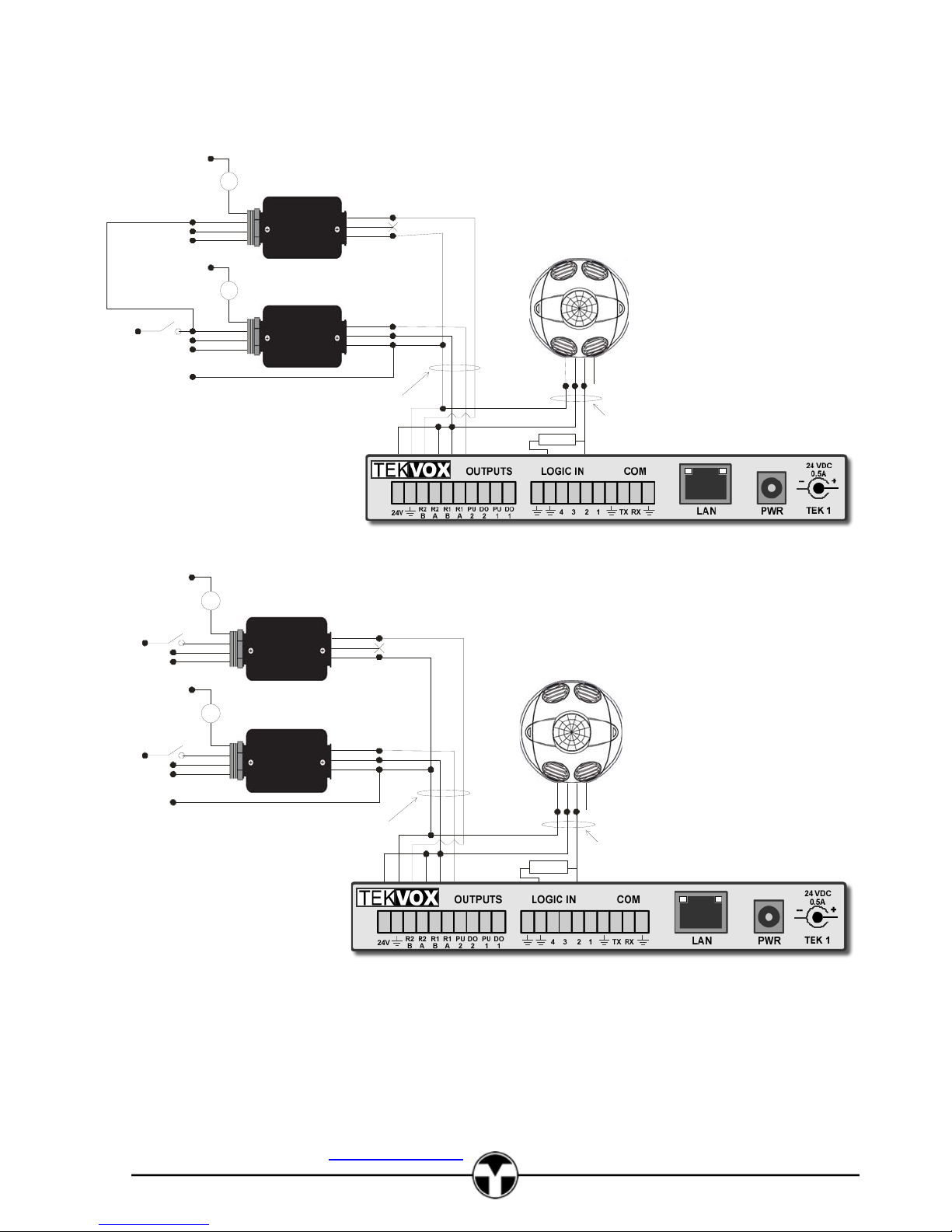
9. At the TEK 1 connect the wires as shown and place a jumper between +24 and R2-A and R1-B.
10. Place the occupancy sensor in a location where there is no air
blowing across it and connect to the TEK 1 using a 3 conductor
cable like the West Penn 25231B. The occupancy sensor first
detects a person walking into a room by its IR sensor in the
center of the unit. Once someone is detected, the ultrasonic’s
are turned on to pickup small movements. It is best to have the
ultrasonic vents pointed towards the instructor. For more
information see http://www.tekvox.com/downloads/DS-
Occupancy.pdf
11. To test the occupancy sensor set the B3 switch to on and then
back off. This switch is near the black timer adjustment knob.
Place the cover back on walkout of the room. The lights should
go off in 60 seconds. Wait 60 seconds and make certain the
lights do not go back on while you are waiting. When you walk
back into the room the lights will go back on. The sensor will
remain in test mode for 15 minutes.
12. Once power is applied to the TEK 1, its LAN connector Link light (Left) should show green. If not, there
is no network.
13. Once everything is working properly disconnect and reconnect power. The TEK 1 will send an Email
with its IP address and serial number.
Installation Guide
and start a procedure
Page 2
Neutral (White)
Hot (Black)
Neutral (White)
Ground (Green)
Neutral (Whit e)
Light Switch
Hot (Black)
Neutral (Whit e)
Light Switch
Hot (Black)
Rear Lights
Relay
Rear
(Blue)
Blue
Black
White
Relay
(Blue)
Blue
Black
White
Add ground wire from building steel.
Power Pack
Front Lights
Power Pack
Rear
Front
Blue
Red
Black
Blue
Red
Black
4 Conductor Cable
Green
Black
Power Packs Installed
Side -By-Side Using
1 Light Switch
White
Blue
Gray
Red
Black
Red
Black
Green
White
Black
Red
+24
GND
R2-B
R2-A
R1-B
R1-A
2K Res istor
N/C
3 Conductor Cable
White
Neut ral (Whit e)
Hot (Black)
Hot (Black)
Neut ral (Whi te)
Neut ral (Whit e)
Hot (Black)
Hot (Black)
Neut ral (Whi te)
Ground (Green)
TEKVOX, Inc. – 210.348.6565 –
78232
Rear Lights
Relay
Rear
Light Switch
Light Switch
(Blue)
Blue
Black
White
Front Lights
Relay
Front
(Blue)
Blue
Black
White
Add ground wire from building steel.
Rear
Power Pack
Front
Power Pack
Blue
Red
Black
Green
Black
Power Packs Installed
Side-By-Side Using
2 Light Switches
Blue
Red
Black
4 Conductor Cable
www.TEKVOX.com San Antonio, TX
White
Red
Blue
Gray
Black
Red
Black
Green
White
Black
Red
+24
GND
R2-B
R2-A
R1-B
R1-A
2K Res istor
N/C
3 Conductor Cable
White
2
Page 3

)
d
Neutral (Wh ite)
Hot (Black)
Neutral (Wh ite)
Ground (Green)
Neut ral (Whi te
Light Switch
Hot (Black)
Neut ral (Whi te)
Light Switch
Hot (Black)
Rear Lights
Relay
Rear
(Blue)
Blue
Black
White
Relay
(Blue)
Blue
Black
White
Add ground wire from building steel.
Power Pack
Front Lights
Power Pack
Rear
Front
Blue
Red
Black
2 Conductor Cable
Blue
Red
Black
4 Conductor Cable
TEK CMC-2 Classroom Media Center
Red
Black
Data Sheet
Power Packs Installe
Apart Us ing
1 Light Switch
White
Blue
Gray
Red
Black
2K Resistor
N/C
3 Conductor Cable
White
Red
Black
Green
White
Black
Red
+24
GND
R2-B
R2-A
R1-B
R1-A
Neut ral (Whit e)
Hot (Black)
Hot (Black)
Neut ral (Whi te)
Neut ral (Whit e)
Hot (Black)
Hot (Black)
Neut ral (Whi te)
Ground (Green)
Rear Lights
Relay
Rear
Light Switch
Light Switch
(Blue)
Blue
Black
White
Front Lights
Relay
Front
(Blue)
Blue
Black
White
Add ground wire from building steel.
Rear
Power Pack
Front
Power Pack
Blue
Red
Black
2 Conductor Cable
Blue
Red
Black
4 Conductor Cable
Red
Black
Power Packs Installed
Apart Using
2 Light Switches
White
Red
Blue
Gray
Black
Red
Black
Green
White
Black
Red
+24
GND
R2-B
R2-A
R1-B
R1-A
2K Res istor
N/C
3 Conductor Cable
White
Page 4

Neut ral (Whit e)
Hot (Black)
Hot (Black)
Neut ral (Whi te)
Neut ral (Whit e)
Hot (Black)
Hot (Black)
Neut ral (Whi te)
Neut ral (Whit e)
Hot (Black)
Hot (Black)
Neut ral (Whi te)
Ground (Green)
Rear Lights Zone 1
Relay
Rear
Light Switch
Light Switch
Light Switch
(Blue)
Blue
Black
White
Rear Lights Zone 2
Relay
Rear
(Blue)
Blue
Black
White
Front Lights
Relay
Front
(Blue)
Blue
Black
White
Add ground wire from building steel.
Rear 1
Power Pack
Rear 2
Power Pack
Front
Power Pack
Blue
Red
Black
2 Conductor Cable
Blue
Red
Black
2 Conductor Cable
Blue
Red
Black
4 Conductor Cable
Red
Black
Power Packs Installed
Apart Using
3 Light Switches
Black
Red
Black
Red Red
White
Red
Blue
Gray
Black
Red
Black Black
Green
White
Black
Red
+24
GND
R2-B
R2-A
R1-B
R1-A
2K Res istor
N/C
3 Conductor Cable
White
TEKVOX, Inc. – 210.348.6565 –
78232
4
www.TEKVOX.com San Antonio, TX
 Loading...