

Page 1

TEK 51T-HD
Compact Presentation Switcher
User’s Manual
April 12, 2015
Page 2
This manual is for operation instruction only, not for any maintenance usage.
Please refer to the dealers for the latest details.
This manual is copyright TEKVOX, INC. All rights reserved. No part of this
publication may be copied or reproduced without the prior written consent of
TEKVOX, INC.
NOTICE:
1. Please read this user manual carefully before using this product.
2. PoC is short for “Power over Cable”. Do not plug into RJ45 until connections are
made and tested at both ends.
3. Only use the TEK TPHD402PR or compatible receiver with the TEK 51T-HD.
4. The item “far-end” means the device (e.g. display device, 3rd party RS232 device
etc.) connected with TEK TPHD402PR.
5. Take notice to 4.6 Instructions of VGA Converting Cable when using.
Page 3
TEK 51T-HD Compact Presentation Switcher
Table of Contents
1. Introduction ................................................................................................................. 1
1.1 Introduction to TEK 51T-HD ............................................................................... 1
1.2 Features ............................................................................................................ 1
1.3 Package Contents ............................................................................................. 2
2. Product Appearance ................................................................................................... 3
2.1 TEK 51T-HD Front Panel ................................................................................... 3
2.2 TEK 51T-HD Rear Panel ................................................................................... 4
3. System Connection ..................................................................................................... 5
3.1 Installation Precautions ..................................................................................... 5
3.2 System Diagram ................................................................................................ 6
3.3 Connection Procedure ....................................................................................... 6
3.4 Connection of Microphone ................................................................................. 7
3.5 Application ......................................................................................................... 9
4. System Operations ..................................................................................................... 9
4.1 Operations of Buttons ........................................................................................ 9
Resolution Adjusting ................................................................................ 9 4.1.1
Switching Operations ............................................................................. 10 4.1.2
Operation Examples: ............................................................................. 11 4.1.3
Firmware Updating ................................................................................ 11 4.1.4
Volume Adjusting ................................................................................... 11
4.1.5
Using the OSD Menu ............................................................................. 11 4.1.6
4.2 Operations of IR .............................................................................................. 12
IR Remote ............................................................................................. 12 4.2.1
IR Operations ........................................................................................ 13 4.2.2
4.3 Operations of CEC Function ............................................................................ 14
4.4 Operations of RS232 Control ........................................................................... 15
RS232 Communication Commands ...................................................... 16 4.4.1
RS232 Control Modes ........................................................................... 23 4.4.2
4.5 Operations in OSD Menu................................................................................. 25
1. Optional settings ................................................................................................... 25
2. Image settings ...................................................................................................... 25
TEKVOX, INC. www.tekvox.com
Page 4
TEK 51T-HD Compact Presentation Switcher
3. Audio settings ....................................................................................................... 25
4. System settings .................................................................................................... 25
Option .................................................................................................... 25 4.5.1
Picture ................................................................................................... 27 4.5.2
Sound .................................................................................................... 28 4.5.3
Setup ..................................................................................................... 29 4.5.4
4.6 Instructions of VGA Converting Cable ............................................................. 29
5. Specification ............................................................................................................. 31
6. Panel Drawing .......................................................................................................... 33
7. Troubleshooting & Maintenance ............................................................................... 34
8. Safety Operation Guide ............................................................................................ 35
After-sales Service ........................................................................................................ 36
TEKVOX, INC. www.tekvox.com
Page 5
TEK 51T-HD Compact Presentation Switcher
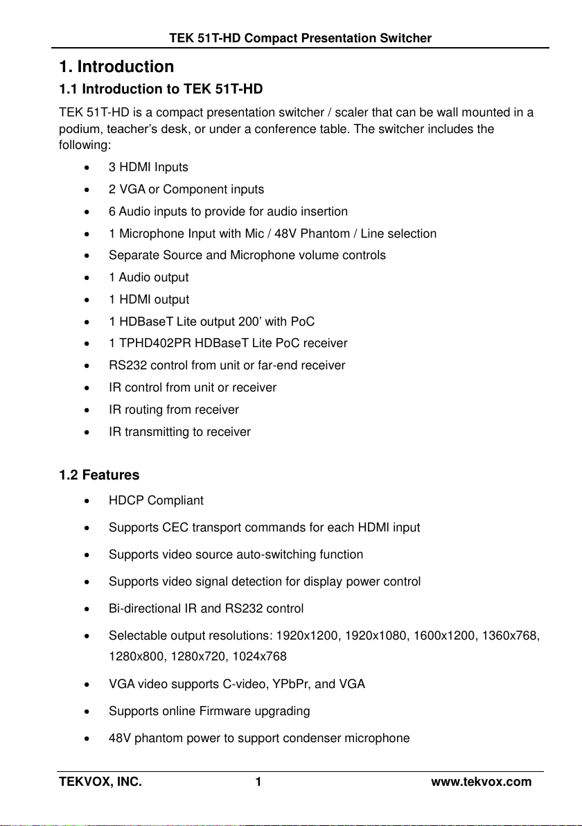
1. Introduction
1.1 Introduction to TEK 51T-HD
TEK 51T-HD is a compact presentation switcher / scaler that can be wall mounted in a
podium, teacher’s desk, or under a conference table. The switcher includes the
following:
3 HDMI Inputs
2 VGA or Component inputs
6 Audio inputs to provide for audio insertion
1 Microphone Input with Mic / 48V Phantom / Line selection
Separate Source and Microphone volume controls
1 Audio output
1 HDMI output
1 HDBaseT Lite output 200’ with PoC
1 TPHD402PR HDBaseT Lite PoC receiver
RS232 control from unit or far-end receiver
IR control from unit or receiver
IR routing from receiver
IR transmitting to receiver
1.2 Features
HDCP Compliant
Supports CEC transport commands for each HDMI input
Supports video source auto-switching function
Supports video signal detection for display power control
Bi-directional IR and RS232 control
Selectable output resolutions: 1920x1200, 1920x1080, 1600x1200, 1360x768,
1280x800, 1280x720, 1024x768
VGA video supports C-video, YPbPr, and VGA
Supports online Firmware upgrading
48V phantom power to support condenser microphone
TEKVOX, INC. 1 www.tekvox.com
Page 6
TEK 51T-HD Compact Presentation Switcher
MIC input supports balance/unbalance signal
3-level MIC input, supports condenser microphone, dynamic microphone, and
wireless microphone.
Controllable via button, IR, and RS232.
Powerful OSD function.
TekMonitor Macro commands
1.3 Package Contents
1 x TEK 51T-HD
2 x Mounting ears (separate from TEK 51T-HD)
1 x Power Adapter (DC 12V)
1 x IR remote
1 x IR receiver
5 x IR emitters
1 x RS232 cable
2 x VGA converting cables (male VGA to female YPbPr, length: 16”)
7 x Captive screw connectors
4 x Screws (black color)
6 x Plastic cushions
1 x User Manual
Notes:Please confirm that the product and accessories are all included. If they are not,
please contact your dealer.
TEKVOX, INC. 2 www.tekvox.com
Page 7
TEK 51T-HD Compact Presentation Switcher
2. Product Appearance
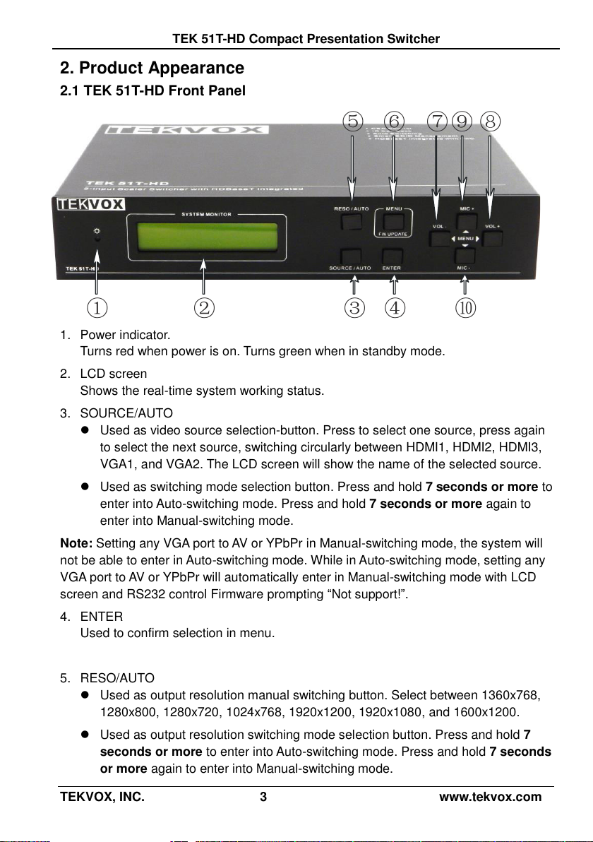
2.1 TEK 51T-HD Front Panel
1. Power indicator.
Turns red when power is on. Turns green when in standby mode.
2. LCD screen
Shows the real-time system working status.
3. SOURCE/AUTO
Used as video source selection-button. Press to select one source, press again
to select the next source, switching circularly between HDMI1, HDMI2, HDMI3,
VGA1, and VGA2. The LCD screen will show the name of the selected source.
Used as switching mode selection button. Press and hold 7 seconds or more to
enter into Auto-switching mode. Press and hold 7 seconds or more again to
enter into Manual-switching mode.
Note: Setting any VGA port to AV or YPbPr in Manual-switching mode, the system will
not be able to enter in Auto-switching mode. While in Auto-switching mode, setting any
VGA port to AV or YPbPr will automatically enter in Manual-switching mode with LCD
screen and RS232 control Firmware prompting “Not support!”.
4. ENTER
Used to confirm selection in menu.
5. RESO/AUTO
Used as output resolution manual switching button. Select between 1360x768,
1280x800, 1280x720, 1024x768, 1920x1200, 1920x1080, and 1600x1200.
Used as output resolution switching mode selection button. Press and hold 7
seconds or more to enter into Auto-switching mode. Press and hold 7 seconds
or more again to enter into Manual-switching mode.
TEKVOX, INC. 3 www.tekvox.com
Page 8

TEK 51T-HD Compact Presentation Switcher
c d
a b
6. MENU/FWUPDATE
Used as menu button. Press it to enter the OSD menu.
Used as Firmware updating button. Press and hold 7 seconds or more to enter
into the Firmware updating procedure.
7. VOL- / Menu Left
Used as volume down button.
Used as direction button Menu Left when in menu mode.
8. VOL+ / Menu Right
Used as volume up button.
Used as direction button Menu Right when in menu mode.
9. MIC+ / Menu Up
Used as MIC volume up button.
Used as direction button Menu Up when in menu mode.
10. MIC- / Menu Down
Used as MIC volume down button.
Used as direction button Menu Down when in menu mode.
2.2 TEK 51T-HD Rear Panel
1. AUDIO INPUT
3 HDMI audio and 2 VGA audio inputs. User can choose any one audio (embedded
HDMI audio or external input audio) for HDMI audio input by using RS232
commands.
2. AUDIO OUTPUT
Audio output port. The audio comes from the input audio corresponding to the
selected video source and mixed with MIC audio.
TEKVOX, INC. 4 www.tekvox.com
Page 9
TEK 51T-HD Compact Presentation Switcher
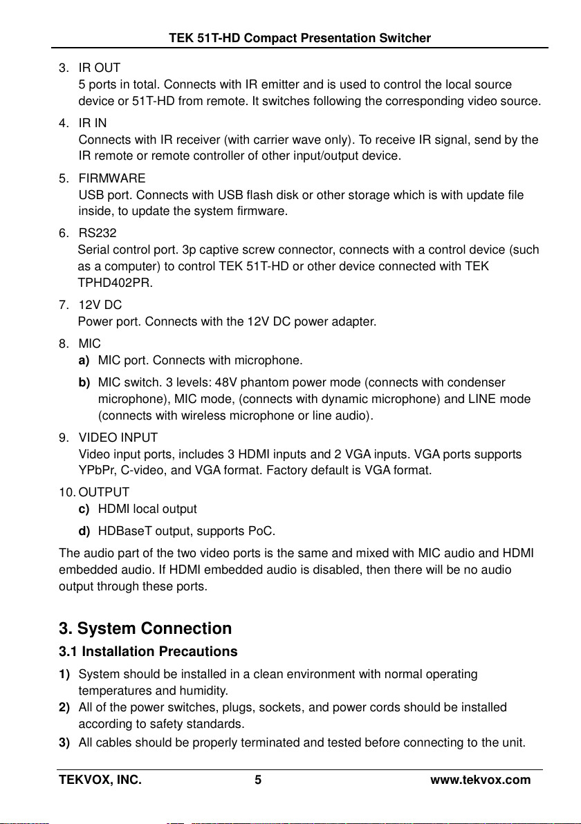
3. IR OUT
5 ports in total. Connects with IR emitter and is used to control the local source
device or 51T-HD from remote. It switches following the corresponding video source.
4. IR IN
Connects with IR receiver (with carrier wave only). To receive IR signal, send by the
IR remote or remote controller of other input/output device.
5. FIRMWARE
USB port. Connects with USB flash disk or other storage which is with update file
inside, to update the system firmware.
6. RS232
Serial control port. 3p captive screw connector, connects with a control device (such
as a computer) to control TEK 51T-HD or other device connected with TEK
TPHD402PR.
7. 12V DC
Power port. Connects with the 12V DC power adapter.
8. MIC
a) MIC port. Connects with microphone.
b) MIC switch. 3 levels: 48V phantom power mode (connects with condenser
microphone), MIC mode, (connects with dynamic microphone) and LINE mode
(connects with wireless microphone or line audio).
9. VIDEO INPUT
Video input ports, includes 3 HDMI inputs and 2 VGA inputs. VGA ports supports
YPbPr, C-video, and VGA format. Factory default is VGA format.
10. OUTPUT
c) HDMI local output
d) HDBaseT output, supports PoC.
The audio part of the two video ports is the same and mixed with MIC audio and HDMI
embedded audio. If HDMI embedded audio is disabled, then there will be no audio
output through these ports.
3. System Connection
3.1 Installation Precautions
1) System should be installed in a clean environment with normal operating
temperatures and humidity.
2) All of the power switches, plugs, sockets, and power cords should be installed
according to safety standards.
3) All cables should be properly terminated and tested before connecting to the unit.
TEKVOX, INC. 5 www.tekvox.com
Page 10
TEK 51T-HD Compact Presentation Switcher
4) All devices should be connected before powering the unit on.
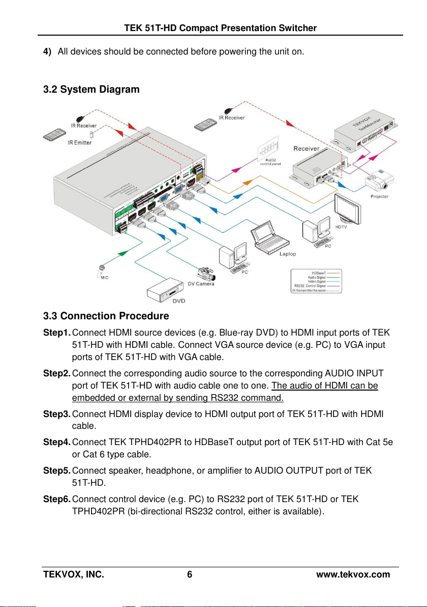
3.2 System Diagram
3.3 Connection Procedure
Step1. Connect HDMI source devices (e.g. Blue-ray DVD) to HDMI input ports of TEK
51T-HD with HDMI cable. Connect VGA source device (e.g. PC) to VGA input
ports of TEK 51T-HD with VGA cable.
Step2. Connect the corresponding audio source to the corresponding AUDIO INPUT
port of TEK 51T-HD with audio cable one to one. The audio of HDMI can be
embedded or external by sending RS232 command.
Step3. Connect HDMI display device to HDMI output port of TEK 51T-HD with HDMI
cable.
Step4. Connect TEK TPHD402PR to HDBaseT output port of TEK 51T-HD with Cat 5e
or Cat 6 type cable.
Step5. Connect speaker, headphone, or amplifier to AUDIO OUTPUT port of TEK
51T-HD.
Step6. Connect control device (e.g. PC) to RS232 port of TEK 51T-HD or TEK
TPHD402PR (bi-directional RS232 control, either is available).
TEKVOX, INC. 6 www.tekvox.com
Page 11
TEK 51T-HD Compact Presentation Switcher
Step7. Both TEK 51T-HD and TEK TPHD402PR have IR IN and OUT. When one model
is used for IR signal receiver, the IR signal must be sent out by the other model.
For example: When “IR IN” of TEK 51T-HD connects with an IR receiver, the IR
transmitter must connect to IR OUT of TPHD402PR.
The IR signal can be transmitted bi-directionally between TEK 51T-HD and
TEK TPHD402PR.
Step8. Select MIC level and connect right microphone to MIC input port. MIC audio will
be transmitted to AUDIO OUTPUT port and mixed with source audio.
Step9. Connect DC12V power adaptor to the power port (TEK TPHD402PR is able to
get power from TEK 51T-HD).
3.4 Connection of Microphone
TEK 51T-HD provides one 3-level microphone input to accommodate different
microphone input modes, including 48V phantom power mode, MIC mode, and LINE
mode.
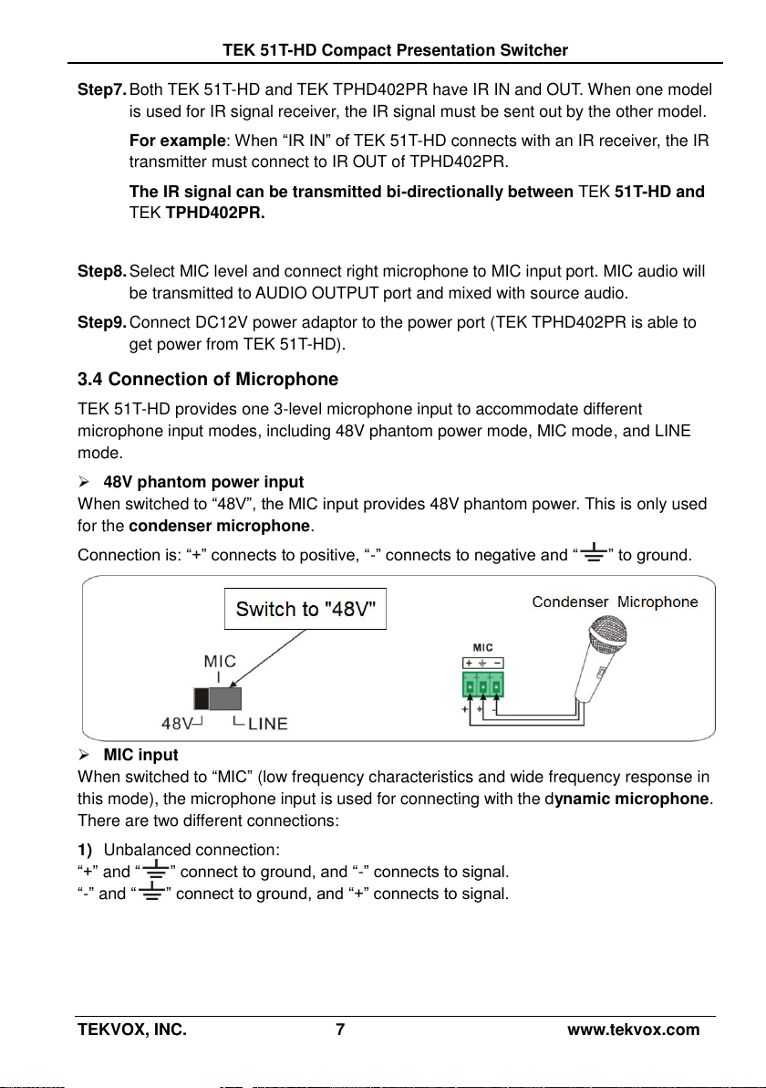
48V phantom power input
When switched to “48V”, the MIC input provides 48V phantom power. This is only used
for the condenser microphone.
Connection is: “+” connects to positive, “-” connects to negative and “ ” to ground.
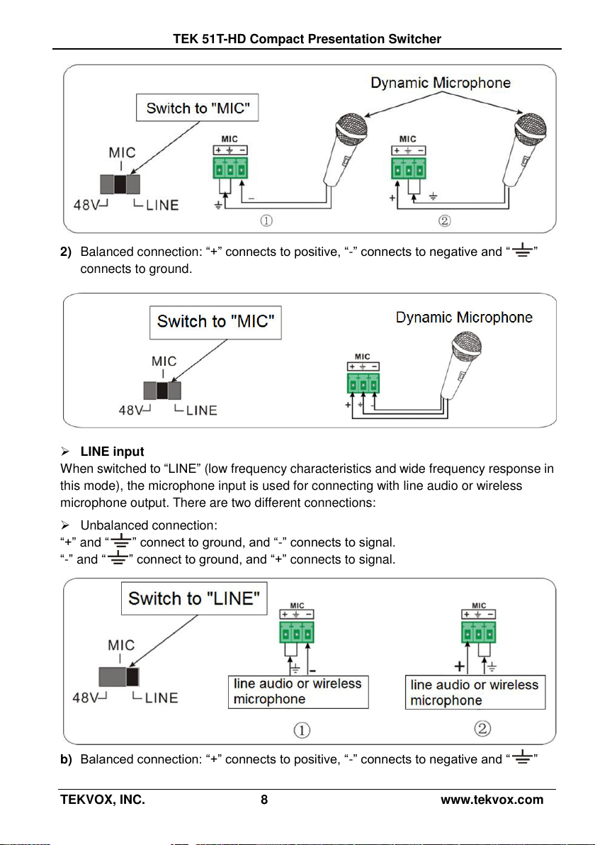
MIC input
When switched to “MIC” (low frequency characteristics and wide frequency response in
this mode), the microphone input is used for connecting with the dynamic microphone.
There are two different connections:
1) Unbalanced connection:
“+” and “ ” connect to ground, and “-” connects to signal.
“-” and “ ” connect to ground, and “+” connects to signal.
TEKVOX, INC. 7 www.tekvox.com
Page 12
TEK 51T-HD Compact Presentation Switcher
2) Balanced connection: “+” connects to positive, “-” connects to negative and “ ”
connects to ground.
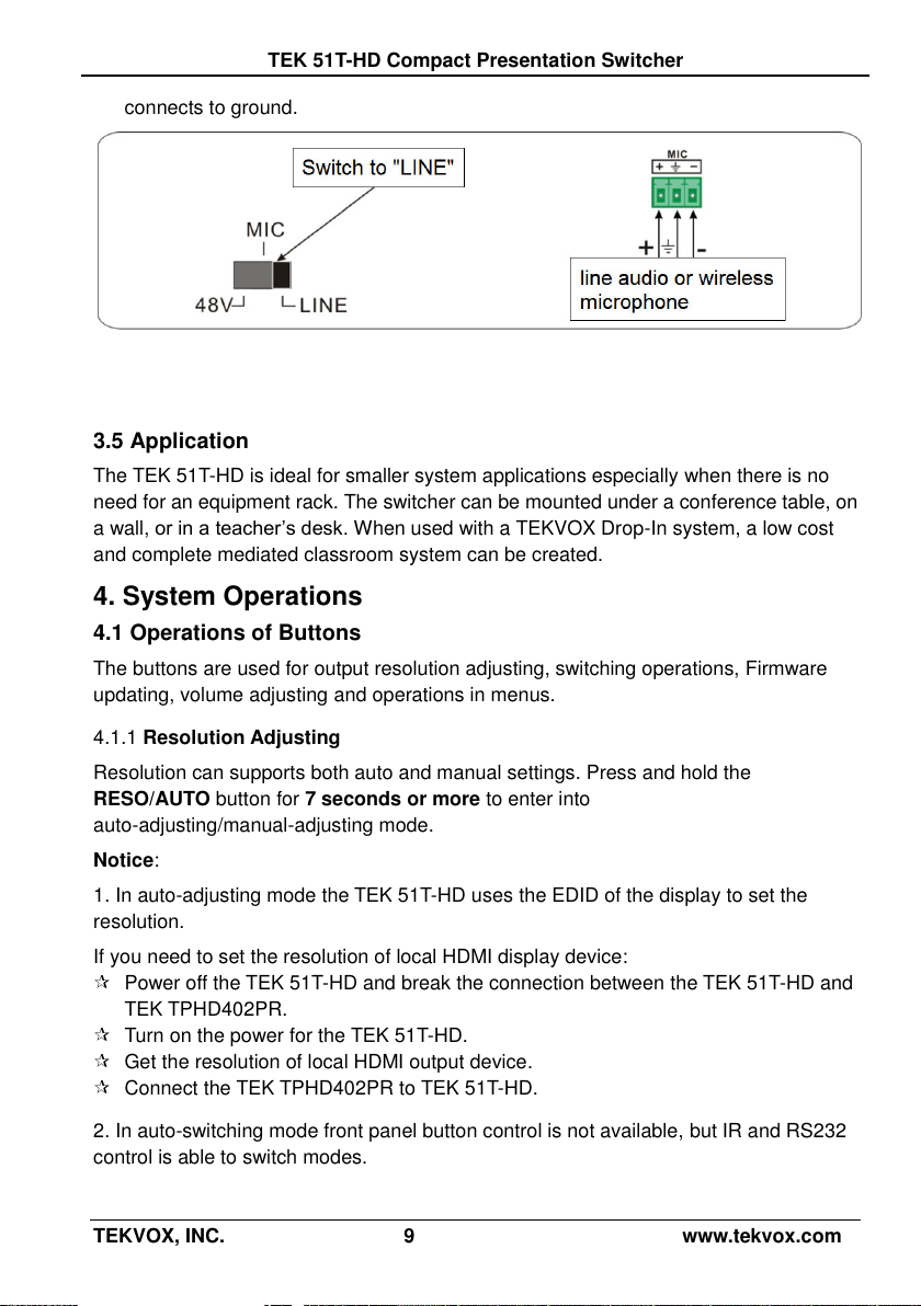
LINE input
When switched to “LINE” (low frequency characteristics and wide frequency response in
this mode), the microphone input is used for connecting with line audio or wireless
microphone output. There are two different connections:
Unbalanced connection:
“+” and “ ” connect to ground, and “-” connects to signal.
“-” and “ ” connect to ground, and “+” connects to signal.
b) Balanced connection: “+” connects to positive, “-” connects to negative and “ ”
TEKVOX, INC. 8 www.tekvox.com
Page 13
TEK 51T-HD Compact Presentation Switcher
connects to ground.
3.5 Application
The TEK 51T-HD is ideal for smaller system applications especially when there is no
need for an equipment rack. The switcher can be mounted under a conference table, on
a wall, or in a teacher’s desk. When used with a TEKVOX Drop-In system, a low cost
and complete mediated classroom system can be created.
4. System Operations
4.1 Operations of Buttons
The buttons are used for output resolution adjusting, switching operations, Firmware
updating, volume adjusting and operations in menus.
Resolution Adjusting 4.1.1
Resolution can supports both auto and manual settings. Press and hold the
RESO/AUTO button for 7 seconds or more to enter into
auto-adjusting/manual-adjusting mode.
Notice:
1. In auto-adjusting mode the TEK 51T-HD uses the EDID of the display to set the
resolution.
If you need to set the resolution of local HDMI display device:
Power off the TEK 51T-HD and break the connection between the TEK 51T-HD and
TEK TPHD402PR.
Turn on the power for the TEK 51T-HD.
Get the resolution of local HDMI output device.
Connect the TEK TPHD402PR to TEK 51T-HD.
2. In auto-switching mode front panel button control is not available, but IR and RS232
control is able to switch modes.
TEKVOX, INC. 9 www.tekvox.com
Page 14

TEK 51T-HD Compact Presentation Switcher
IN: HDMI1 MANUAL
1280 X 720
IN: HDMI1 AUTO
1280 X 720
Auto-switching function
Switching Operations
4.1.2
The TEK 51T-HD Supports both auto-switching and manual switching. Press and hold
the SOURCE/AUTO button for 7 seconds or more to enter into
auto-switching/manual-switching mode.
The display result is showed as below:
The display result will be shown for 2 seconds.
The auto-switching mode follows the listed principles:
New input principle
Once it detects a new input signal, the TEK 51T-HD switches to this new signal
automatically.
Power rebooting principle
TEK 51T-HD offers this feature to remember the last displayed signal when
rebooting. While rebooting, the TEK 51T-HD automatically enters into auto-switching
mode and detects all inputs to memorize their connection status.
If the signal last displayed is still available, then it will choose the signal to output. If
not, there will be no signal on its outputs.
Signal removing principle
Once it has removed the current display signal, the TEK 51T-HD will detect all input
signals with priority from INPUT 1 to INPUT 5. It will select the first detected signal to
its output.
Notice: The Auto-switching function works only when an input detects a new signal, loss
of a signal, or power rebooting. With any VGA port set to AV or YPbPr the system is not
able to enter in Auto-switching mode.
TEKVOX, INC. 10 www.tekvox.com
Page 15

TEK 51T-HD Compact Presentation Switcher
Operation Examples:
4.1.3
Connect INPUT 2, INPUT 4, and INPUT 5 ports to their source devices and select
INPUT 4. Press and hold the front key SOURCE/AUTO for 7 seconds or more to enter
into auto-switching mode.
No change on inputs and the output remains on INPUT 4.
Connect INPUT 3 with a source device and the output switches to INPUT 3.
Remove the signal from INPUT 3 and the TEK 51T-HD will search for input signals
on inputs 1 through 5. When it detects INPUT has video, it will choose INPUT 2 to
output.
Cycle power on the TEK 51T-HD and it will select INPUT 2 to output.
Firmware Updating 4.1.4
Firmware updating will update the firmware of this scaler-switcher.
The TEK 51T-HD supports firmware updating via USB flash drive. Use the following to
update:
1) Copy the file “MERGE_51T-HD.bin” to the root directory of a USB flash drive. (Make
sure the file is copied to the root directory for normal use. The “MERGE_51T-HD.bin”
file is provided and authorized by TEKVOX engineering department).
2) Plug the USB flash drive into the TEK 51T-HD USB port on its rear panel.
3) Press the button “MENU” for 7 seconds or more to update the firmware
automatically. If this does not work, you can also use the OSD and select “Software
Update” or send RS232 command 50689%.
4) After unit is finished updating firmware, you need to perform a factory reset by
sending RS232 command 50617%. It might also be possible to use the OSD menu
by pressing Menu then Left and select Restore Factory Default. If the TEK 51T is
controlled from the receiver, then it is necessary to send the command 50788% or
perform the Drop-in Setup procedure.
Volume Adjusting 4.1.5
Volume control uses the same buttons for the OSD menu.
Press VOL -- to decrease line volume, VOL + to increase.
Press MIC – to decrease MIC volume, MIC + to increase.
Using the OSD Menu 4.1.6
Press the MENU button to enter in OSD menu and use the UP, DOWN, LEFT and
RIGHT buttons to select. Press the ENTER button to confirm selection. The MENU
button is also used to exit the OSD menu.
TEKVOX, INC. 11 www.tekvox.com
Page 16

TEK 51T-HD Compact Presentation Switcher
ᬅ Standby button
To enter in/exit standby mode.
ᬆ Input channel selection buttons
INPUT 1 is for HDMI1, INPUT 2 for
HDMI2…INPUT 5 for VGA2. AUTO button:
Enable/disable auto-switching mode.
ᬇ Volume adjusting buttons
MIC-/+: decrease/increase MIC volume
LINE-/+: decrease/increase line volume
MIC MUTE: mute/unmute MIC audio
LINE MUTE: mute/unmute line audio
ᬈ Menu operation buttons
MENU: press to enter the OSD menu or return to
the previous menu. EXIT: exit OSD menu.
OK: confirm button. ,,, : UP/DWON/LEFT/
RIGHT button, for value setting or page-turn,
Buttons in area a are also able to work in CEC
mode to enter the menu of HDMI source device.
P.P, ZOOM, S.M: shortcut button, to select display
mode.
ᬉ Resolution selection buttons
Select the resolution by pressing the
corresponding button. AUTO is for auto-selecting
the best resolution.
ᬊ CEC function buttons
These are for the HDMI input signal which
supports CEC. Includes PLAY, PAUSE, STOP,
MENU, REV (reverse) and FWD (forward).
4.2 Operations of IR
IR Remote 4.2.1
IR signals are transmitted bi-directionally between the TEK 51T-HD and TEK
TPHD402PR. Use the IR remote at the receiver to control the TEK 51T-HD or HDMI
source devices (via CEC function buttons).
TEKVOX, INC. 12 www.tekvox.com
Page 17

TEK 51T-HD Compact Presentation Switcher
IR Operations
4.2.2
The 5 IR OUT ports correspond to the 5 video inputs respectively. Routing of IR signals
from the unit or the receiver follow to the video source selection.
1) Control far-end device from local
Control the TEK 51T-HD or far-end display device from an IR receiver at the unit by
using a corresponding remote controller.
TEKVOX, INC. 13 www.tekvox.com
Page 18

TEK 51T-HD Compact Presentation Switcher
2) Control local device from remote
Control the TEK 51T-HD or local source device from an IR receiver at HDBaseT receiver
by using a corresponding remote controller.
4.3 Operations of CEC Function
The TEK 51T-HD supports CEC commands and can be enabled and disabled through
RS232 commands or the OSD menu. If the HDMI source device supports CEC and its
CEC operation is enabled when the TEK 51T-HD enters in standby / startup mode, then
the source device will automatically enter standby / startup mode.
Devices that support CEC functions can be controlled with basic operations (play, pause,
fast forward, fast reverse, menu, etc.). Users are able to control the TEK 51T-HD and
HDMI source device via the IR remote or RS232 commands from the TEK 51T-HD. Note
that not all CEC enabled devices operate the same and may act differently between
devices.
Commands for CEC function: “50686%” (enable CEC) and “50687%” (disable CEC).
TEKVOX, INC. 14 www.tekvox.com
Page 19

TEK 51T-HD Compact Presentation Switcher
Situation
Working Status
CEC: on, Standby: on
Press STANDBY button on IR remote: TEK 51T-HD enters in
standby mode, so do all HDMI source devices.
Press STANDBY button again on IR remote, TEK 51T-HD
exits standby mode, only the HDMI source device selected to
starts working.
CEC: on, Standby: off
Press STANDBY button on IR remote: TEK 51T-HD enters in
standby mode, HDMI 1~3 source devices remain on.
CEC: on
Use CEC function buttons, ▲,▼, , and OK buttons on
IR remote to control HDMI source devices including play,
pause, fast forward, fast reverse, and operations in menu.
CEC: off
Unable to control HDMI source devices through IR remote
The working status related to CEC and STANDBY is showed as below:
CEC: Control HDMI source devices by IR remote of TEK 51T-HD
4.4 Operations of RS232 Control
Use the RS232 port on the TEK 51T-HD or TEK TPHD402PR to control the TEK
51T-HD using a third party RS232 device.
TEKVOX, INC. 15 www.tekvox.com
Page 20

TEK 51T-HD Compact Presentation Switcher
Command
Function
Feedback Example
Switch Commands
50701%
Switch to HDMI 1 input
Switch to HDMI 1
50702%
Switch to HDMI 2 input
Switch to HDMI 2
50703%
Switch to HDMI 3 input
Switch to HDMI 3
50704%
Switch to VGA 1/YPbPr 1/AV 1 input
Switch to VGA 1/YPbPr 1/AV 1
50705%
Switch to VGA 2/YPbPr 2/AV 2 input
Switch to VGA 2/YPbPr 2/AV 2
50680%
Select VGA 1 for INPUT 4
Input 4 Set & Switch to VGA 1
50681%
Select YPbPr 1 for INPUT 4
Input 4 Set & Switch to AV 1
50682%
Select AV 1 for INPUT 4
Input 4 Set & Switch to AV 1
50683%
Select VGA 2 for INPUT 5
Input 5 Set & Switch to VGA 2
50684%
Select YPbPr 2 for INPUT 5
Input 5 Set & Switch to YPbPr 2
50685%
Select AV 2 for INPUT 5
Input 5 Set & Switch to AV 2
50785%
Enable auto-switching
Auto Switching
50786%
Disable auto-switching
Manual Switching
Audio Commands
50600%
MUTE line audio
LINE Mute
50601%
Un-Mute line audio
LINE Unmute
50602%
Line audio volume up
LINE Volume: xx
50603%
Line audio volume down
LINE Volume: xx
501xx%
Set the Line volume (xx = 00 to 60)
LINE Volume: xx
50720%
Mute LINE audio & MIC audio
LINE Mute
MIC Mute
50721%
Unmute LINE audio & MIC audio
LINE Unmute
MIC Unmute
50722%
Mute MIC audio
MIC Mute
50723%
Unmute MIC audio
MIC Unmute
50694%
Enable Mic precedence
Mic precedence: enable
RS232 Communication Commands
4.4.1
Communication protocol: RS232 Communication Protocol
Baud rate: 9600 Data bit: 8 Stop bit: 1 Parity bit: none
TEKVOX, INC. 16 www.tekvox.com
Page 21

TEK 51T-HD Compact Presentation Switcher
Command
Function
Feedback Example
50695%
Disable Mic precedence
Mic precedence: disable
50696%
Check Mic precedence status
Mic precedence: XXXX
50724%
MIC volume up
MIC Volume: xx
50725%
MIC volume down
MIC Volume: xx
508xx%
Set MIC volume (xx = 00 to 60)
MIC Volume: xx
50706%
Set HDMI 1 embedded audio
HDMI 1 Audio from Embedded
50707%
Set HDMI 2 external audio
HDMI 1 Audio from LINE
50708%
Set HDMI 2 embedded audio
HDMI 2 Audio from Embedded
50709%
Set HDMI 2 external audio
HDMI 2 Audio from LINE
50710%
Set HDMI 3 embedded audio
HDMI 3 Audio from Embedded
50711%
Set HDMI 3 external audio
HDMI 3 Audio from LINE
Resolution Commands
50619%
Set resolution to 1360X768 HD
Resolution: 1360x768
50626%
Set resolution to 1024X768 XGA
Resolution: 1024x768
50627%
Set resolution to 1280X720 720P
Resolution: 1280x720
50628%
Set resolution to 1280X800 WXGA
Resolution: 1280x800
50629%
Set resolution to 1920X1080 1080P
Resolution: 1920x1080
50620%
Set resolution to1920X1200 WUXGA
Resolution: 1920x1200
50621%
Set resolution to1600X1200 UXGA
Resolution: 1600x1200
TEKVOX, INC. 17 www.tekvox.com
Page 22

TEK 51T-HD Compact Presentation Switcher
Command
Function
Feedback Example
Setup Commands
50797%
Standby
Go to standby!
50697%
Power On
Wake up!
50604%
Lock the front panel buttons
Front Panel lock
50605%
Unlock the front panel buttons
Front Panel Unlock
502xx%
Set the brightness (xx = 00 to 99)
Brightness: xx
503xx%
Set the contrast (xx = 00 to 99)
Contrast: xx
504xx%
Set the saturation (xx = 00 to 99)
Saturation: xx
505xx%
Set the sharpness (xx = 00 to 99)
Sharpness: xx
50607%
Auto-adjust the color temperature
Color Temperature: xx
50608%
Set the aspect ratio
Aspect Ratio: xx
50614%
Set the picture mode
Picture Mode: xx
50615%
Set SM audio mode
Sound Mode: xx
50655%
Enable Freeze
Freeze: enable
50656%
Disable Freeze
Freeze: disable
50646%
Enable Volume Icon display
Volume Icon: enable
50647%
Disable Volume Icon display
Volume Icon: disable
50648%
Enable HDMI embedded audio output
Embedded Audio Output: enable
50649%
Disable HDMI embedded audio output
Embedded Audio Output: disable
50761%
Disable mute icon of LINE audio
LINE Mute Icon: disable
50762%
Enable mute icon of LINE audio
LINE Mute Icon: enable
50763%
Disable mute icon of MIC audio
MIC Mute Icon: disable
50764%
Enable mute icon of MIC audio
MIC Mute Icon: enable
50765%
Enable freeze icon
Freeze Icon: enable
50766%
Disable freeze icon
Freeze Icon: disable
50644%
Enable Icon status
Input Icon: enable
50645%
Disable Icon status
Input Icon: disable
TEKVOX, INC. 18 www.tekvox.com
Page 23

TEK 51T-HD Compact Presentation Switcher
Command
Function
Feedback Example
50650%
Get the Icon status
Input Icon: xx
50606%
Auto-adjust the VGA only
VGA Input Auto
50699%
Get the system version
Version Vx.x.x
50688%
Enable MIC noise detecting
MIC detect: enable
50689%
Disable MIC noise detecting
MIC detect: disable
50690%
Get MIC noise detecting statue
MIC detect: XXXX
50791%
HDCP Active
HDCP Active
50792%
HDCP Manual
HDCP Manual
50795%
Get HDCP/ Active HDCP
HDCP Active
Get HDCP/ Manual HDCP
HDCP Manual
HDCP OFF/ON
50782%
EDID management, copy the best
resolution data of one output to HDMI
input
Manage HDMI input with
preferred timing
timing table=[1]
Resolution:1920x1080
50787%
Enable serial control of display:
Control Scaler & Display from local
RS232
RS232 Mode 1: RS232 Control
Scaler & Remote
50788%
Enable TekMonitor serial control:
Control Scaler from both local RS232
and Receiver. Must be sent to local
RS232 to enable TekMonitor control at
receiver.
RS232 Mode 2: RS232 &
Remote Control Scaler
50698%
Software update
50617%
Reset to factory defaults
Factory Reset
Menu Commands
50609%
OK for OSD selection
Key: ok
50610%
LEFT button
Key: left
50611%
RIGHT button
Key: right
TEKVOX, INC. 19 www.tekvox.com
Page 24

TEK 51T-HD Compact Presentation Switcher
Command
Function
Feedback Example
50612%
UP button
Key: up
50613%
DOWN button
Key: down
50616%
MENU button (enter OSD)
OSD: Enter
50618%
EXIT button (exit OSD)
OSD: Exit
Inquire Commands
50630%
Get the volume level
LINE Volume: xx
MIC Volume: xx
50631%
Get the input source
Input: xx
50632%
Get the output resolution
Resolution: xx
50633%
Get the image mode
Picture Mode: xx
50634%
Get the audio mode
Sound Mode: xx
50635%
Get the image aspect ratio
Aspect Ratio: xx
50636%
Get the brightness
Brightness: xx
50637%
Get the contrast
Contrast: xx
50638%
Get the saturation
Saturation: xx
50639%
Get sharpness
Sharpness: xx
50640%
Get the color temperature
Color Temperature: xx
50651%
Get Volume Icon display status
Volume Icon: xxxx
50652%
Get Digital audio output status
Embedded Audio Output:
enable/disable
50712%
Get the audio input sources for HDMI
1, 2, 3
HDMI1 Audio from XXXX port
HDMI2 Audio from XXXX port
HDMI3 Audio from XXXX port
50751%
Get the LINE mute status
LINE Mute/Unmute
50752%
Get the MIC mute status
MIC Mute/Unmute
50753%
Get the freeze status
Freeze: enable/disable
50754%
Get the panel locked status
Front Panel Lock/UnLock
50783%
Get current status
Line Volume:XX
TEKVOX, INC. 20 www.tekvox.com
Page 25

TEK 51T-HD Compact Presentation Switcher
Command
Function
Feedback Example
Display statues including MIC, LINE
audio, Resolution, Output Audio
on/off, Manual/ Auto-switching modes
Mic Volume:XX
Input:XXXX
Resolution:XXXX
Adjustment Commands
50678%
Enable screen output adjusting
Enter Output Position Adjust
50679%
Disable screen output adjusting
Exit Output Position Adjust
50670%
Move the image to right
Output Position Adjust X xx
50671%
Move the image to left
Output Position Adjust X xx
50672%
Move the image up
Output Position Adjust Y XX
50673%
Move the image down
Output Position Adjust Y xx
50674%
Stretch left from left side (increase
image width)
Output Width Adjust xx
50675%
Pull right from left side (decrease
image width)
Output Width Adjust xx
50676%
Stretch upwards from top side
(increase image height)
Output Height Adjust xx
CEC Commands
50687%
Disable CEC
HDMI CEC OFF
50686%
Enable CEC
HDMI CEC ON
50901%
Play & Pause
CEC cmd: play&pause
50902%
Stop
CEC cmd: stop
50903%
Menu
CEC cmd: menu
50904%
Reverse
CEC cmd: rev
50905%
Forward
CEC cmd: fwd
50906%
Up
CEC cmd: up
50907%
Down
CEC cmd: down
50908%
Left
CEC cmd: left
50909%
Right
CEC cmd: right
TEKVOX, INC. 21 www.tekvox.com
Page 26

TEK 51T-HD Compact Presentation Switcher
Command
Function
Feedback Example
50910%
Confirm command
CEC cmd: select
50911%
Exit command Tog Menu
CEC cmd: exit
50912%
Pause
CEC cmd: pause
50913%
Selected Device Power On
Source power on
50914%
Selected Device Power Off
Source power off
50915%
Enable CEC Auto Power
Enable CEC Auto Power
50916%
Disable CEC Auto Power
Disable CEC Auto Power
TEKVOX Commands
511xx%
TekMonitor Macro Command
(xx= 01-30)
CMD: 01 - 30
Video Detection Feedback
Signal On / Signal Off
Note:
1. Turn on/ off HDCP auto-management by sending serial commands.
a) When HDCP is set to active, whether or not the output source has
HDCP depends on the input source. If the input source has HDCP, the
output will also have HDCP, and vice versa.
2. When HDCP is set to Manual, the output always enables HDCP.
3. Screen output adjusting avails only when the screen output adjusting is on.
Send command 50678% to turn it on.
4. CEC commands with grey background avails only when CEC is on.
5. MIC precedence: In Mute mode, if the MIC noise detecting is on, the device
will unmute MIC automatically given the outer noise exceeds the limit of noise
detection. If you send 50696% to enable MIC precedence, the device will not
be able to change the mute mode, regardless of the noise level.
TEKVOX, INC. 22 www.tekvox.com
Page 27

TEK 51T-HD Compact Presentation Switcher
RS232 Control Modes
4.4.2
There are two RS232 operational control modes for the TEK 51T-HD to function with.
One allows a 3rd party control system to operate the TEK 51T-HD using the local RS232
port on the unit while also allowing the control system to send RS232 commands to a
display via the RS232 on the HDBaseT receiver. The other (TEKVOX default) allows the
TEK 51T-HD to be controlled from both the local RS232 port on both the unit and the
HDBaseT receiver.
Control TEK 51T-HD and Display from Local RS232 port 4.4.2.1
This is the normal operation of the TEK 51T-HD which also works with a
TekMonitor at the receiver.
1. Connect the RS232 port of TEK 51T-HD to RS232 port of PC.
2. Send the command 50787% via RS232 communication software.
3. Send the right command of TEK 51T-HD or other remote RS232 device
connected in present system. Connect as shown below:
Control 51T-HD and display from local
TEKVOX, INC. 23 www.tekvox.com
Page 28

TEK 51T-HD Compact Presentation Switcher
Control TEK 51T-HD from Local or Remote
4.4.2.2
Control TEK 51T-HD from local
This is the normal operation of the TEK 51T-HD which also works with a
TekMonitor at the HDBaseT receiver.
1. Connect the RS232 port of TEK 51T-HD to RS232 port of PC.
2. Send the command 50788% (serial control mode 1, factory default) via
RS232 communication software.
3. Send any control command for the TEK 51T-HD from either RS232 port on
unit or HDBaseT receiver. Connect as shown below:
Control TEK 51T-HD from local
Control TEK 51T-HD from HDBaseT Receiver
Control TEK 51T-HD from HDBaseT Receiver
TEKVOX, INC. 24 www.tekvox.com
Page 29

TEK 51T-HD Compact Presentation Switcher
4.5 Operations in OSD Menu
The TEK 51T-HD provides a powerful OSD operation menu and contains four parts:
1. Optional settings
2. Image settings
3. Audio settings
4. System settings
Press the MENU button on the front panel (or MENU button on IR remote/send
command 50616%) to enter into OSD menu.
Option 4.5.1
Includes Output Adjust, Input4/5 Select, HDMI1/2/3 Audio select and Software Update
(USB)
Output Adjust: Adjust output image position (X: horizontal direction and Y: vertical
direction) and ratio aspect (width and height).
Input4 Select: Select video source format for VGA input. This includes AV 1 (C-video
signal), VGA 1 (VGA signal), and YPbPr 1 (Component video signal). Use the ENTER
button to select the desired source format.
TEKVOX, INC. 25 www.tekvox.com
Page 30

TEK 51T-HD Compact Presentation Switcher
Input5 Select: Select video source for VGA input. This includes AV 2 (C-video signal),
VGA 2 (VGA signal), and YPbPr 2 (Component video signal). Use the ENTER button to
select the desired source format.
For INPUT4 and INPUT5, when change for new format signal:
1. First, select a format through this menu (the signal format changed while the video
source is still the same).
2. Second, switch the present signal channel off (e.g. switch to another channel).
3. Finally, switch to the channel INPUT4/INPUT5 again.
HDMI1 Audio Select: switch between Embedded and Line to choose the desired audio
output port for HDMI1.
HDMI2 Audio Select: switch between Embedded and Line to choose the desired audio
output port for HDMI2.
HDMI3 Audio Select: switch between Embedded and Line to choose the desired audio
output port for HDMI3.
Software Update (USB): Insert the USB flash disk with updating file to USB port of 51D,
to update the software through this menu.
TEKVOX, INC. 26 www.tekvox.com
Page 31

TEK 51T-HD Compact Presentation Switcher
Picture
4.5.2
Includes Picture Mode, Color Temperature, Aspect Ratio, Noise Reduction, Screen and
Color Range.
Picture mode: Includes Dynamic, Standard, Mild, and User. You may adjust the image
contrast and brightness in User mode.
Color Temperature: Includes Cool, Medium, Warm and User. You may set the values
for Red, Green and Blue (RGB) in User mode.
Aspect Ratio: Includes Native, 4:3, 16:9, Zoom1, Zoom2, Just Scan, Panorama, and
Point To Point. VGA format will only support 4:3, 16:9, and Point to Point.
Noise Reduction (not for VGA format): Includes Off, Low, Middle, High, and Default.
Screen: (not for HDMI source): Includes Auto Adjust, Horizontal, Vertical, Size and
Phase.
Color Range (not for VGA format): Includes 0~255 and 16~235. Use the ENTER button
to select the color range.
TEKVOX, INC. 27 www.tekvox.com
Page 32

TEK 51T-HD Compact Presentation Switcher
Sound
4.5.3
Including Sound Mode, Surround Sound and EQ
Sound mode: Includes Standard, Music, Movie, Sports, and User. You may
support treble and bass settings in User mode.
Surround Sound: Includes Off, Surround, and SRS Trusurround XT.
EQ: To adjust the sound balance.
TEKVOX, INC. 28 www.tekvox.com
Page 33

TEK 51T-HD Compact Presentation Switcher
Setup
4.5.4
Including OSD Language, Blending, HDMI, CEC and OSD Duration
OSD Language: Supports 14 languages including English (default) and Mandarin.
Blending: Includes Low, Middle, High and Off. Use the ENTER button to select.
HDMI CEC: Enable/disable CEC and auto-standby function. Default: CEC on,
STANDBY on.
OSD Duration: Includes 5 s, 10 s, 15 s, and Off. “s” is for Second.
4.6 Instructions of VGA Converting Cable
VGA inputs support YPbPr and C-video sources. The TEK 51T-HD comes with 2 VGA
converting cables to comply with these signals.
When you need to select these signals as an input source, switch to channel INPUT 4
(or INPUT 5) and set the signal type in OSD.
Connect with Component Video (YPbPr) Source
A. Operation Examples:
1. Via front panel buttons & OSD
Press the MENU button on the front panel to enter into OSD. In the OPTION
setting menu, set “INPUT 4 Select” to YPbPr1, and “INPUT 5 Select” to YPbPr2.
Afterwards, press the SOURCE/AUTO button on the front panel to switch to
TEKVOX, INC. 29 www.tekvox.com
Page 34

TEK 51T-HD Compact Presentation Switcher
YPbPr1 or YPbPr2 source.
2. Via RS232 commands
Send command 50681% (or 50684%) to switch to YPbPr1 (or YPbPr2) source.
3. Via IR remote & OSD
Press the MENU button on the IR remote to enter into OSD and enter into the
OPTION setting menu, set “INPUT 4 Select” to YPbPr1, and “INPUT 5 Select” to
YPbPr2. After setting, press INPUT 4 (or INPUT 5) button to switch to YPbPr1
(or YPbPr2) source.
B. Connecting the VGA converting cable like this:
Connect with Composite Video (C-VIDEO) Source
A. Operation Examples:
1. Via front panel buttons and OSD
Press the MENU button on the front panel to enter into OSD and enter into the
OPTION setting menu: set “INPUT 4 Select” to AV1, and “INPUT 5 Select” to
AV2. After setting, press SOURCE/AUTO button on front panel to switch to AV1
or AV2 source.
2. Via RS232 commands
Send command 50682% (or 50685%) to switch to YPbPr1 (or YPbPr2) source.
3. Via IR remote & OSD
Press MENU button on IR remote to enter into OSD and in the OPTION setting
menu, set “INPUT 4 Select” to AV1, and “INPUT 5 Select” to AV2. After setting,
press INPUT 4 (or INPUT 5) button to switch to AV1 (or AV2) source.
B. Connecting the VGA converting cable like this:
TEKVOX, INC. 30 www.tekvox.com
Page 35

TEK 51T-HD Compact Presentation Switcher
Video Input
Video Output
Input
3 HDMI
2 VGA
Output
1 HDMI
1 HDBaseT
Input
Connector
3 female HDMI
2 female VGA (15 pin)
Output
Connector
1 female HDMI
1 RJ45
Video Signal
HDMI, YPbPr, C-video,
VGA
Video Signal
1 HDMI
1 HDBaseT
IR Input
IR Output
Input
1 IR IN
Output
5 IR OUT
Input
Connector
3.5mm mini jack
Output
Connector
3.5mm mini jack
Video General
Resolution
Range
1024x768, 1280x720,
1280x800, 1920x1080,
1600x1200, 1920x1200
Bandwidth
HDMI:4.95Gbps(1.65Gb
ps per color)
C-Video:150MHz
YPbPr: 170MHz
VGA: 375MHz
Maximum
Pixel Clock
165MHz
Video
Impedance
75Ω
Gain
0dB
Input / Output
Level
0.5V~2.0Vp-p
HDCP
Compliant with DVI & HDMI 1.3 standards
Audio Input
Audio output
Input
3 Dual-mono stereo
audio for HDMI
2 Dual-mono stereo
audio for VGA (Support
C-VIDEO, YPbPr, VGA)
Output
1 stereo
MIC Input
1 balanced for Mic or
Line level with 48V
Phantom.
Input
Impedance
>10kΩ
Output
Impedance
50KΩ
5. Specification
TEKVOX, INC. 31 www.tekvox.com
Page 36

TEK 51T-HD Compact Presentation Switcher
Audio General
Frequency
Response
20Hz~20K Hz
Stereo
Channel
Separation
>80dB @1KHz
CMRR
>90dB @20Hz to 20K
Hz
Control Parts
Control/
Remote
IR remote, Buttons &
RS232
Pin
Configuration
2 = TX, 3 = RX, 5 =
GND
General
Temperature
-20 ~ +70℃
Humidity
10% ~ 90%
Power
Supply
DC12V ± 0.5V
Power
Consumption
8W, supply power to
51T-HD and
TPHD402PR separately
16W, 51T-HD supplies
power to TPHD402PR
Case
Dimension
W220x H44x D148mm
Product
Weight
0.67Kg
TEKVOX, INC. 32 www.tekvox.com
Page 37

TEK 51T-HD Compact Presentation Switcher
6. Panel Drawing
TEKVOX, INC. 33 www.tekvox.com
Page 38

TEK 51T-HD Compact Presentation Switcher
7. Troubleshooting & Maintenance
1) When the output image is looks like noise or snowflakes, common problems
include but are not limited to:
Poor quality cable. Please try another higher quality cable.
The video cables are loose. Try reconnecting them.
2) When it is not able to manage EDID, the HDMI cable may be broken or
loose.
3) When a user cannot control the switcher by computer through its COM port,
check the COM port number in the software and make sure the COM port is
in good condition.
4) If the POWER indicator doesn’t work or respond to any operation, ensure
the power cord’s connection is secure.
5) No output image when switching:
Use an oscilloscope or multi-meter to determine if there is a signal at the
input and output end. If there is no signal, the connection cord may be
broken or have loose connections. Use a new cable and/or attempt to
reconnect them.
If none of these methods have worked, there may be something wrong
with the switcher. Contact your dealer if this is the case.
6) If the static becomes stronger when connecting the video/audio connectors,
the grounding may be incorrect. If it is incorrect, the connection may
damage the switcher.
7) If it is not able to control the scaler-switcher from front panel buttons, but
able through RS232 commands, the front panel buttons are probably locked.
Send command 50605% to unlock.
8) If the scaler-switcher cannot be controlled by the buttons on the front panel,
RS232 port, or IR remote, the switcher may be broken. Send it to the dealer
for repairs.
TEKVOX, INC. 34 www.tekvox.com
210.348.6565
Page 39

TEK 51T-HD Compact Presentation Switcher
8. Safety Operation Guide
In order to guarantee the reliable operation of the equipment and safety of the
staff, please abide by the following proceeding in regards to installation, usage
and maintenance:
1) The system must be earthed properly. Please do not use two blade plugs
and ensure the alternating power supply ranged from 100v to 240v and from
50Hz to 60Hz.
2) Do not put the device in a place that is too hot or cold.
3) Since the unit produces some heat, the working environment should be
maintained with ventilation
4) Cut off the general power switch in humid weather or if it is left unused for a
long period of time.
5) Before following operation, ensure that the alternating current wire is pulled
out of the power supply:
Take off or reship any components of the equipment.
Take off or rejoin any pin or other link of the equipment.
6) Unless you are a professional or given permission, DO NOT try to open the
casing of the equipment. DO NOT attempt to repair it on your own as this
may increase the risk of an accident or damage to the equipment.
7) DO NOT splash liquid in or around the equipment.
TEKVOX, INC. 35
www.tekvox.com
Page 40

TEK 51T-HD Compact Presentation Switcher
After-sales Service
1) If there are problems while using the TEK 51T-HD, please reference the user
manual first. Any transport costs are borne by the users during the warranty.
2) If you email our after-sales department or make a call, please provide us with
the following information:
Product version and name.
Detailed failure situations.
The formation of the cases.
3) We offer products with a five-year warranty, which starts from the first day of
purchase (The purchase invoice shall prevail).
4) Warranties will not be honored in the following cases:
A product is beyond the warranty.
Damage due to incorrect usage or repairing.
Damage due to device assembly operations by the maintenance company
non-assigned.
No certificate or invoice as the proof of warranty.
The product model shown on the warranty card does not match the model
of the product for repairing or had been altered.
Damage caused by force majeure.
Remarks: For any questions or concerns, please contact your distributor or email
TEKVOX at
support@tekvox.com
Tel: 210.348.6565
Fax: 713.490.3135
Email: sales@tekvox.com
Website: www.tekvox.com
TEKVOX, INC. 36
www.tekvox.com
Page 41

 Loading...