

Page 1

POWERTXT USA
3G power socket
User Manual
Manual version 2.0
Page 2

POWERTXT USA 3G power socket USER MANUAL
POWERTXT USA 3G power socket
Thank you for purchasing the POWERTXT USA.
POWERTXT USA GSM power socket is a remote controlled socket
consisting of a GSM module. The power supply output can be turned on
or off remotely by the SMS command or local controlled by pressing
button.
All services and functions need to be supported by the GSM network
and a SIM card.
This brochure suits for POWERTXT USA model.
Details of the functioning and advanced operation of this socket are
described in this instruction manual.
2
Page 3

POWERTXT USA 3G power socket USER MANUAL
For your safety ................................................................ 4
Exception clause ............................................................. 4
1.1 Package contents ...................................................... 5
1.2 Sockets instructions ............................................ 5
1.3 Light indicator .......................................................... 5
2.1 User authorization level ............................................ 5
2.2 About the SMS Command ......................................... 5
3.1 Start to use ................................................................ 6
3.2.1 Register Master-number. ........................................ 6
3.2.2 Change Master number ......................................... 6
3.5 Control socket power ................................................ 6
3.6 Delay control the socket output ................................ 6
3.7 Calendar control ....................................................... 7
3.8 Thermostat control .................................................... 7
3.9 Temperature alarm .................................................... 8
3.10 SMS when on/off button pressed ............................. 8
3.11 SMS when power lost or restore .............................. 8
3.12 SMS notification to User ......................................... 8
3.13 Check status ............................................................ 9
3.14 Weak GSM signal notification ................................. 9
3.15 Change password .................................................... 9
3.16 Resetting the socket ................................................. 9
4 Main Technical Parameters ......................................... 9
Appendix: SMS commands list ...................................... 11
3
Page 4
POWERTXT USA 3G power socket USER MANUAL
1. Purchase a GSM SIM card (mobile phone card) from GSM
network service provider and install it in the socket. This
SIM card number is referred as POWERTXT USA number
on this brochure.
2. The user needs to activate the Caller ID Presentation
function of SIM card, and deactivate PIN code of the SIM.
Contact with GSM network service provider for support.
3. Change the original password at the beginning use. Be
sure to keep the password and SIM card number secret.
Do not disclose this information to anyone other than the
authorized users in order to ensure your safety.
For your safety
This socket was designed for home or office use. Do not use it on the electrical appliance which is for industry or business operation, for example, iatrical
appliances, large heaters and refrigerate s.
Before using this socket, make sure that the mobile phones can be used well in the area, otherwise, do not put this socket into operation.
The power consumption of the appliances connected with the socket cannot exceed 3600W and the current cannot exceed 16A.
The electrical appliance which power consumption is higher than 1500W must be grounded.
Do not make two plugs of socket short circuit.
Do not touch the socket jack by any metal objects or hand.
This socket was designed for indoor use. Don’t use it in wet, chemically aggressive or dusty environment.
Do not open the case unless maintenance needed.
Do not keep shaking or fall down this socket, otherwise it can be damaged.
This socket is a wireless signal t ransm ission s ocket. K eep it away from e lectro nic equ ipment l ikely to int erfer e with t he w ireless si gnals, i n or der to av oid si gnal s
interference.
Switch off this socket and mobile phone when entering areas marked "Explosive", "Might explode", "Closed wireless transceiver sockets" etc.
Do not cast this socket in a fire, as this may cause explosion.
This socket should only be operated from power approved by the socket manufacturer. The use of any other types of power may damage the socket.
Keep the socket and its accessories out of the children reach.
Exception clause
1. We operate on a policy of continuous development. We reserve the right to make changes and improvements to any of the sockets described in this document
without prior notice.
2. For the latest socket information, please visit: http://www.simpal.cn. We don’t guarantee for the document veracity, reliability or any content except regulate in
proper laws. Including no guarantee for socket suitable market or suitable area promise.
3. We hold no responsibility for the illeg al us e of thi s sock et.
4. We hold no responsibility for any loss of income or any special, incidental, consequential or indirect damages howsoever caused.
5. The contents of this document are provided “as is”. Except as required by applicable law, no warranties of any kind, either expressed or implied, including, but
not limited to the accuracy, reliability or contents of this document. We reserve the right to revise this document or cancel some functions at any time without
prior notice.
4
Page 5
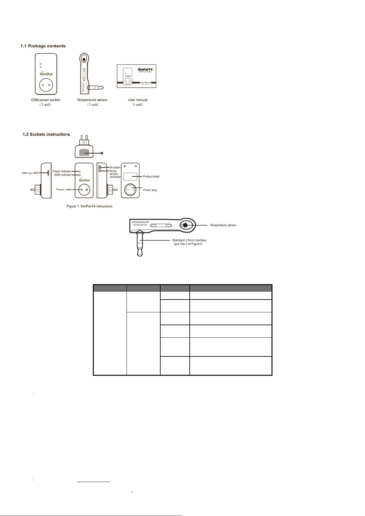
1.1 P
a
o
g
s
s
a
-
o
echa
e
b
S
e
W
N
S
n
u
t
s
s
h
a
a
w
t
:
p
S
r
s
w
o
P
t
o
v
n
s
M
c
a
e
m
o
u
e
e
T
C
r
F
s
S
b
Cls
F
T
s
c
m
o
o
o
e
o
e
h
a
p
p
e
y
t
h
t
m
e
M
e
n
w
1.2 S
POWERTXT U
ckage conte
ckets instr
A 3G pow er s
ts
ctions
cket USER
ANUAL
Figure 2: T
1.3 Li
ht indicator
Model
OWERTXT
USA
2.1 U
er authoriza
Socket
ettings can be
There
re two mobile p
Master
user (“Master”):
Onl
y one Master h
In
rder to enable
allo
ed for a socke
Family
users (“Family”)
Th
re are four famil
nge alert.
Th
other mobile
2.2 A
out the SMS
SM
command fo
Th
maximum digit
PO
ERTXT USA
ote
ion level
et or adjusted v
one user contro
s authorization
ll the functions
.
:
ies have authori
hone users ha
Command
mat: #code#co
that are allows
ill reply to the u
ia a SMS comm
lling levels:
o use all feature
n the socket, th
zation to use co
e no authorizati
tent#.
for the phone n
er after it receiv
Indicator
Power icon
indicator
Wireless
i
on indicato
nd.
s of POWERTX
Master must
mands of swit
n to control the
mber is sixteen.
s the SMS co
mperature sens
Action
urning offS
onstant
l
ight
lash
lowly
lowly
reath
ontinues
ight in 3
econds
lash fast
USA.
tore his/ her mo
h on or cut off t
socket.
mand.
5
r Instruction
cket power out
cket power out
S
S
arching GSM n
W
rking in standb
st to factory set
R
Pr
cess SMS com
bile number in t
e socket outpu
St
us
ut OFF
ut ON
twork
mode.
ing
mand
e socket’s me
, check socket t
ory. Only one
mperature valu
aster’s mobile
or receive po
umber is
er status
Page 6

POWERTXT USA 3G power socket USER MANUAL
The “#” symbol must not be ignored when typing an SMS command.
No allow any space within the commands.
3.1 Start to use
Installed SIM card to POWERTXT USA GSM power socket: you will see a SIM card slot at the side, make the SIM card metal contact upside and hardly push
the SIM card until SIM card fixed.
Insert the temperature sensor into the I/O port until it is seized.
Power on:
1. Plug the POWERTXT USA in 230V wall socket.
The GSM LED will be flashing slowly for about 15 seconds, and turn to slowly breathe status, breathe LED means the socket already register GSM network, its
ready to working.
The socket default power output is OFF.
2. Insert the plug of electronic appliance in the POWERTXT USA electrical outlet.
3. M button (See 5 on Figure1) can be pressed for about one second to switch on or off the socket output.
After adding user numbers to the socket, users can send SMS command to control the power supply output.
Note:
1. If the GSM indicator light is flash slowly all the time, which imply the SIM card working abnormally, all functions of this socket are invalid.
2. Check GSM network signal of the using place:
GSM network’s signal strength may affect the socket feature. Therefore, before using, the user should ensure that socket is used in an area with a
strong GSM network signal.
For the first time use, the user should perform a test-run by sending SMS to the socket. This allows the user to check the GSM network connection
of the socket.
3.2.1 Register Master-number.
Sending following SMS to socket SIM card number from your mobile phone (the phone number will be the Master number):
Register Master-number on the socket: #00# (1)
3.2.2 Change Master number
Master sends following SMS message in order to:
Change master-number: #14#NewMasterNumber (2)
NewMasterNumber should be the new Master mobile phone numb er.
3.3.1 Register Family-number
Up to 4 Family-number can be stored on GSM socket.
Family-number has the authority to send SMS command to switch on or cut off the socket power output.
Method
Master sends following SMS message in order to:
Register a Family:
Family-Number should be the User’s mobile phone number.
#06#Family-Number# (3)
3.3.2 Check Family number
Master sending SMS to check Family number: #06# (4)
3.3.3 Delete Family
Method
Master sends following SMS message in order to:
Delete a Family: #15#Family-Number# (5)
Delete all Familes: #15# (6)
3.5 Control socket power
Method
Method 1:To press M button one second (See 5 on Figure1).
Method 2:
Master sends following SMS message to socket in order to:
Turn ON socket power output: #01#0# (7)
Turn OFF socket output: #02#0# (8)
3.6 Delay control the socket output
Description
The socket output can be set to delay switch ON/OFF for a period time.
6
Page 7

POWERTXT USA 3G power socket USER MANUAL
Delay control function will auto de activate once manual change socket status by sending SMS or M button, activate calendar c ontrol or thermostat control
When the “delayed switch on the socket” command is received and if the socket output is switched on, the socket output will be switched off immediately and
Method
Delay switching ON output after a certain minutes:
Delay switching OFF output after a certai n minutes:
Minutes are time parameters, its range is 1-720,
Press M button or send other SMS command to change the socket power, it will automatically closed delay control function
will also deactivate the delay control function.
be switch on again as the setting delayed time is reaching. Contrarily, if the socket output is switched off, the output will remain switching off until the setting
delayed time is reaching.
Master sends following SMS message in order to:
#12#0#Minutes#1# (9)
#12#0#Minutes#0# (10)
3.7 Calendar control
3.7.1 Activate calendar control
Description
The socket output can be set to switch on for duration and then be switch off after the duration.
Calendar control function will auto deactivate if user manually change the socket status by SMS or M button, Delay control or Thermostat control will also
deactivate calendar control function.
Method
Master sends following SMS message in order to:
Activate calendar control function: #19#0#1# (11)
Socket will auto switching on or off the output according to the schedule settings.
3.7.2 Set calendar
Description
After successful setting of time duration to switch on the socket output, the schedule parameter will be saved on the socket until socket reset to factory
settings.
Method
Master sends following SMS message in order to:
Set time period to switch on the socket output:
#20#0#WorkDay#StartTime#EndTime# (12)
WorkDay: one digit, the values lie in the range of “0” to “8”.
The following table contains the descriptions of each value:
Value Corresponding day
0 Everyday
1 Monday
2 Tuesday
3 Wednesday
4 Thursday
5 Friday
6 Saturday
7 Sunday
8 Monday to Friday
9 Weekend
StartTime and EndTime: Be consists of 4 digits (hh:mm) and works on a 24 hour clock. If StartTime bigger than EndTime, it will operate until next day
EndTime.
The socket output will switch on at the StartTime and cut off at the EndTime.
For example: #20#0#1#0000#2130# , 0 means the POWERTXT USA, 0000 means time 00:00(hh:mm)AM, 2130 means time 9:30PM.
3.7.3 Deactivate calendar control
Method
Master sends following SMS message in order to:
Deactivate calendar control: #19#0#0# (13)
3.8 Thermostat control
3.8.1 Activate thermostat function
Description
The external temperature sensor must be inserted into the I/O port of socket. The socket power output can be auto controlled according environment
temperature change.
7
Page 8

POWERTXT USA 3G power socket USER MANUAL
Thermostat function will auto deactivate if user manually change the socket status by SMS or M button, Delay control or Calendar control will also deactivate
calendar control fun ction.
There are warming mode and cooling mode for thermostat control function. In warming mode, socket will auto turn on when temperature lower than smaller
temperature value, and turn off when higher than bigger temperature value; Cooling mode, socket will auto turn on when temperature higher than bigger
temperature value and turn off when temperature lower than smaller value.
Method
The Master sends following SMS message in order to:
Activate Thermostat control: #23#0#1# (14)
3.8.2 Set thermostat control parameters
Method
Master sends following SMS message in order to:
Set thermostat control parameters: #24#0#mode#low-temp#high-temp# (15)
Mode parameter can be 1 or 2, Warming mode is 1, cooling mode is 2;
Temp range should be within -10 to 50 degree.
For example #24#0#1#15#25#, it m eans set S imPa-T 4 thermost at co ntrol paramet er, work with w arming mode, and t urn o n socket w hen temperature lower than 15
degree, turn off socket when temper atu re higher than 25 degree.
After successful setting of temperature range, the temperature parameter will be saved on the sock et un til soc ke t res et to fa c tory settings.
3.8.3 Deactivate thermostat control function
Method
Master sends following SMS message in order to:
Deactivate thermostat control: #23#0#0# (16)
3.9 Temperature alarm
Description
A range of temperature can be pre-set onto socket. In this case, if the surroundings temperature is detected out of the pre-set temperature range, POWERTXT
USA socket will auto-send the SMS alarm message to your mobile phone.
This feature depends on the temperature sensor.
Method
Master sends following SMS message in order to:
Activate over-temperature alarm: #21#0#1# (17)
Set temperature range: #22#0#MinTemp#MaxTemp# (18)
MinTemp and MaxTemp: The values can be set within the range of -10 to 50 centigrade degree.
Deactivate temperature alarm:
#21#0#0# (19)
3.10 SMS when on/off button pressed
Description
POWERTXT USA socket will default sending SMS notify Master and Family when on/off button pressed. The Master can enable/disable this SMS notification.
Method
Master sends following SMS message in order to:
SMS when on/off button pressed (Default): #03#1# (20)
Deactivate SMS when on/off button pressed: #03#0# (21)
3.11 SMS when power lost or restore
Description
POWERTXT USA socket will default sending SMS notify when main power supply lost or restore.
Master can enable/disable this SMS notification.
Method
Master sends following SMS message in order to set:
SMS when power lost or restore (Default): #05#1# (22)
Deactivate SMS when power lost or restore: #05#0# (23)
3.12 SMS notification to User
POWERTXT USA socket will sending SMS alert when mains power lost/restore, temperature alert or other information. Default sending SMS to Master and
family. Master can change the setting to cancel SMS to family number.
Method
Master sends following SMS message in order to:
Activate SMS alert to User (Default) #16#1# (24)
Deactivate SMS alert to User #16#0# (25)
8
Page 9

POWERTXT USA 3G power socket USER MANUAL
3.13 Check status
Method
Master or Family sends following SMS message in order to:
Check socket operating status: #07#0# (26)
Check “delayed control” parameters: #34# (27)
Check “Calendar control” parameters: #33# (28)
Check “Thermostat control” parameters: #32# (29)
Check “over-temperature alarm limits” parameters: #35# (30)
3.14 Weak GSM signal notification
The socket can send a SMS notification when the GSM signal strength is too weak. The Master user can enable/disable this SMS notification.
Method
The Master user sends following SMS message in order to set:
Check GSM signal
Activate SMS notification upon weak GSM signal:
Deactivate SMS notification upon weak GSM signal (Default):
#27# (31)
#27#1# (32)
#27#0# (33)
Successful SMS reply
Weak GSM signal strength alert function ON/OFF.
The alerter will send SMS message when it alarms:
Weak GSM signal alert, the CSQ is **.
3.15 Change password
Method
Master sends following SMS message in order to:
Change the password: #04#Oldpassword#Newpassword# (34)
The password is a four digit number.
The original password is 1234.
3.16 Resetting the socket
Description
This function resets all programmed settings to their original values, including cleaning all user number, timing parameter and temperature parameter.
If the setting status is wrong or the malfunctions can’t be corrected, users can restore the socket to its original status to make it work normally.
POWERTXT USA reset factory setting:
Method 1: Press the side M button of the device for 10 seconds.
Method 2: Master sends following SMS message in order to:
Reset POWERTXT USA socket: #08#password# (35)
4 Main Technical Parameters
110~230V/50HZ,
Input power plug
Output power outlet
Operating temperature -10 ~+50℃℃
Store temperature -20 ~+60℃℃
Relative humidity 10-90%,without condensation
Communication GSM PHASE 2/2+
CEE 7/7 hybrid
Schuko/French/American/Australia
plug
110~ 230V/50HZ, 230V/30A(30s),
16A long-duration,
CEE7/4 German “Schuko”/ French/
American/Australia
9
Page 10

POWERTXT USA 3G power socket USER MANUAL
protocols (including data operation)
Data interface GSM SIM 1.8V/3.0V socket
Temperature
sensor range
-10 ~50℃℃
GSM working band 850/900/1800/1900Mhz
10
Page 11
POWERTXT USA 3G power socket USER MANUAL
#
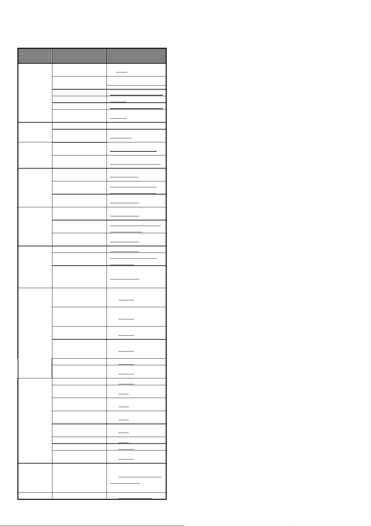
Appendix: SMS commands list
Category Function Command
Define the
users
Change
socket power
status
Delay control
Calendar
control
Thermostat
control
Temperature
alarm
Register
Master-number
Change
Master-number
Add Family-number (3)#06#Family-Number#
Check Family-number (4)#06#
Delete Family-number (5)#15#Family-Number#
Delete all
Family-number
Connect socket power (7)#01#0#
Disconnect socket
power
Delay switching ON
after a certain minutes
Delay switching OFF
after a certain minutes
Activate calendar
control
Set calendar control
parameters
Deactivate calendar
control
Activate thermostat
control
Set thermostat control
parameters
Deactivate thermostat
control
Activate temp-alarm (17)#21#0#1#
Set temp range
Deactivate temp-ala rm (19)#21#0#0#
(1) #00#
2)#14#NewMasterNumber
(6)#15#
(8)#02#0#
(9)#12#0#Minutes#1#
(10) #12#0#Minutes#0#
(11)#19#0#1#
(12)#20#0#WorkDay#
StartTime#EndTime#
(13)#19#0#0#
(14)#23#0#1#
(15)#24#0#mode#low-te
mp#high-temp#
(16)#23#0#0#
(18)#22#0#MinTemp#
MaxTemp#
SMS
notifications
Check status
SMS when on/off
button pressed
(Default)
SMS when on/off
button pressed
function OFF
SMS when power lost
or restore (Default)
SMS when power lost
or restore function
OFF
SMS alert to User (24)#16#1#
SMS alert to User
function OFF
Check status (26)#07#0#
Check “Delayed
Control” status
Check “Calendar
control” status
Check “Thermostat
control” status
Check “temp-alarm”
status
Check GSM signal (31)#27#
Weak GSM signal alert (32)#27#1#
Disable weak GSM
signal alert
(20)#03#1#
(21)#03#0#
(22)#05#1#
(23)#05#0#
(25)#16#0#
(27)#34#
(28)#33#
(29)#32#
(30)#35#
(33)#27#0#
Change
password
Reset socket Reset to factory setting (35)#08#Password#
Change password
(34)#04#old-password#n
ew-password#
11
Page 12

POWERTXT USA 3G power socket USER MANUAL
12
Page 13

POWERTXT USA 3G power socket USER MANUAL
FCC Radiation Exposure Statement:
This equipment complies with FCC radiation exposure limits set forth for an uncontrolled environment. This equipment should be installed and operated with
minimum distance 25cm between the radiator & your body.
FCC Warning
This device complies with Part 15 of the FCC Rules. Operation is subject to the following two conditions:
(1) This device may not cause harmful interference, and (2) this device must accept any interference received, including interference that may cause undesired
operation.
NOTE 1: This equipment has been tested and found to comply with the limits for a Class B digital device, pursuant to part 15 of the FCC Rules. These limits are
designed to provide reasonable prot ecti on a gains t har mful i nterf eren ce i n a r esi denti al in st allatio n. T his e qui pment g ener ates, use s and can r adiate radio fre quency
energy and, if not installed and used in accordance with the instructions, may cause harmful interference to radio communications. However, there is no guarantee
that interference will not occur in a parti cular in stallat ion. If thi s equipmen t does cau se harmful i nterfere nce to rad io or television reception, which can be determined
by turning the equipment off and on, the user is encouraged to try to correct the interference by one or more of the following measures:
- Reorient or relocate the receiving antenna.
- Increase the separation between the equipment and receiver.
-Connect the equipment into an outlet on a circuit different from that to which the receiver is connected.
-Consult the dealer or an experienced radio/TV technician for help.
NOTE 2: Any changes or modifications to this unit not expressly approved by the party responsible for compliance could void the user's authority to operate the
equipment.
13
 Loading...