


DMM4040 and DMM4050
Digital Multimeter
077-0362-01
Technical Reference

Copyright © Tektronix. All rights reserved. Licensed software products are owned by Tektronix
or its subsidiaries or suppliers, and are protected by national copyright laws and international
treaty provisions.
Tektronix products are covered by U.S. and foreign patents, issued and pending. Information in
this publication supersedes that in all previously published material. Specifications and price
change privileges reserved.
TEKTRONIX and TEK are registered trademarks of Tektronix, Inc.
Contacting Tektronix, Inc.
Tektronix, Inc.
14200 SW Karl Braun Drive
P.O. Box 500
Beaverton, OR 97077
USA
For product information, sales, service, and technical support:
- In North America, call 1-800-833-9200.
- Worldwide, visit www.tektronix.com
to find contacts in your area.

Table of Contents
Chapter Title Page
1 Introduction and Specifications ......................................................... 1-1
Introduction ........................................................................................................ 1-3
General Safety Summary ................................................................................... 1-4
To Avoid Fire or Personal Injury .............................................................. 1-4
Symbols and Terms ................................................................................... 1-7
Safety and Electrical Symbols .................................................................. 1-7
Description of IEC 61010 Measurement Categories ................................. 1-8
Organization of the Calibration Manual ............................................................ 1-8
Chapter 1 – Introduction and Specifications ................................................. 1-9
Chapter 2 – General Maintenance ................................................................. 1-9
Chapter 3 – Performance Test and Calibration.............................................. 1-9
Operating Instructions ........................................................................................ 1-9
Accessories ........................................................................................................ 1-9
General Specifications ....................................................................................... 1-11
Power ............................................................................................................. 1-11
Dimensions .................................................................................................... 1-11
Display ........................................................................................................... 1-11
Environment .................................................................................................. 1-11
Triggering ...................................................................................................... 1-11
Memory ......................................................................................................... 1-11
Math Functions .............................................................................................. 1-11
Electrical ........................................................................................................ 1-12
Remote Interfaces .......................................................................................... 1-12
Warranty ........................................................................................................ 1-12
Electrical Specifications .................................................................................... 1-12
DC Voltage Specifications ............................................................................ 1-12
Input Characteristics .................................................................................. 1-12
4050 Accuracy .......................................................................................... 1-13
4040 Accuracy .......................................................................................... 1-13
Additional Errors ....................................................................................... 1-13
AC Voltage Specifications ............................................................................ 1-13
Input Characteristics .................................................................................. 1-14
4040/4050 Accuracy ................................................................................. 1-14
Additional Low Frequency Errors............................................................. 1-15
Resistance ...................................................................................................... 1-15
i

DMM4040 and DMM4050
Technical Reference
DC Current .................................................................................................... 1-16
AC Current .................................................................................................... 1-18
Frequency ...................................................................................................... 1-20
Capacitance (4050 only) ................................................................................ 1-21
Temperature (4050 only) ............................................................................... 1-21
Additional Errors ........................................................................................... 1-21
Continuity ...................................................................................................... 1-21
Diode Test ..................................................................................................... 1-22
Measurement Rates (IEEE488[4]) ................................................................. 1-22
Measurement Uncertainty .................................................................................. 1-22
Interpreting Accuracy Specifications ................................................................. 1-23
24-Hour Accuracy ......................................................................................... 1-23
90-Day and 1-Year Accuracy ........................................................................ 1-23
Temperature Coefficients .............................................................................. 1-23
Configuring for Highest Accuracy Measurements ............................................ 1-23
DC Voltage, DC Current, and Resistance Measurements ............................. 1-23
AC Voltage and AC Current Measurements: ................................................ 1-23
Frequency and Period Measurements: ........................................................... 1-23
Input Characteristics .................................................................................. 1-15
4040/4050 Accuracy ................................................................................. 1-16
Additional Ohms Errors ............................................................................ 1-16
Input Characteristics .................................................................................. 1-16
Accuracy (4040/4050) ............................................................................... 1-17
Additional Current Errors ......................................................................... 1-17
Input Characteristics .................................................................................. 1-18
4040/4050 Accuracy ................................................................................. 1-19
Additional Low Frequency Errors............................................................. 1-20
4040/4050 Accuracy ................................................................................. 1-20
Gate Time vs. Resolution .......................................................................... 1-20
Additional Low Frequency Errors............................................................. 1-20
2 General Maintenance .......................................................................... 2-1
Introduction ........................................................................................................ 2-3
Warranty Repairs and Shipping Information ..................................................... 2-3
General Maintenance Information ..................................................................... 2-3
Required Equipment ...................................................................................... 2-3
Power Requirements ...................................................................................... 2-3
Static Safe Handling ...................................................................................... 2-3
Cleaning ............................................................................................................. 2-4
Fuse Replacement .............................................................................................. 2-4
Line-Power Fuse ............................................................................................ 2-4
Current-Input Fuses ....................................................................................... 2-5
If the Meter Does Not Turn On .......................................................................... 2-7
Display Tests ...................................................................................................... 2-7
Disassembly Procedures .................................................................................... 2-7
General Disassembly ..................................................................................... 2-7
Main Chassis Disassembly ............................................................................ 2-8
Front Panel Disassembly ............................................................................... 2-8
Assembly Procedures ......................................................................................... 2-8
3 Performance Test and Calibration ..................................................... 3-1
Introduction ........................................................................................................ 3-4
Required Equipment .......................................................................................... 3-4
Test Considerations ............................................................................................ 3-6
ii

Contents (continued)
Performance Tests .............................................................................................. 3-6
Volts DC Verification .................................................................................... 3-6
Volts DC Ratio Verification .......................................................................... 3-10
Volts AC and Frequency Verification ........................................................... 3-12
4-Wire Ohms Verification ............................................................................. 3-15
2-Wire Ohms Verification ............................................................................. 3-17
2X4 Test Lead Verification Steps ................................................................. 3-18
Rear Panel Terminal Verification Steps ........................................................ 3-19
Capacitance Verification Steps (DMM4050 only) ........................................ 3-21
DC Current Verification Steps ...................................................................... 3-23
AC Current Verification Steps ...................................................................... 3-25
Adjustment (Calibration) ................................................................................... 3-27
Unlocking the Meter for Adjustments (Calibration) ..................................... 3-27
Unlocking the Meter for Adjustments Over a Remote Interface ................... 3-27
Changing the Calibration Password .............................................................. 3-27
Resetting the Calibration Password ............................................................... 3-28
Changing the Calibration Date ...................................................................... 3-29
Equipment for Calibration ............................................................................. 3-29
Adjustment Process ....................................................................................... 3-29
Aborting a Calibration Process ...................................................................... 3-35
Sample Adjustment Program ......................................................................... 3-35
Appendices
A Verification Forms ...................................................................................... A-1
B Example Adjustment Program .................................................................... B-1
iii

DMM4040 and DMM4050
Technical Reference
iv

List of Tables
Table Title Page
1-1. Accessories ............................................................................................................. 1-9
2-1. Line Voltage to Fuse Rating................................................................................... 2-5
3-1. Required Test Equipment ....................................................................................... 3-4
3-2. DMM4050 DC Volts Verification Steps ................................................................ 3-8
3-3. DMM4040 DC Volts Verification Steps ................................................................ 3-9
3-4. DMM4050 DC Volts Ratio Verification Steps ...................................................... 3-11
3-5. DMM4040 DC Volts Ratio Verification Steps ...................................................... 3-11
3-6. DMM4040/4050 AC Volts Verification Steps ....................................................... 3-13
3-7. DMM4040/4050 AC Volts Frequency Verification Steps ..................................... 3-14
3-8. DMM4040/4050 4-Wire Ohms Verification Steps ................................................ 3-16
3-9. DMM4040/4050 2-Wire Ohms Verification Steps ................................................ 3-18
3-10. DMM4050 Rear-Panel Terminal Verification Steps (Optional Test) .................... 3-20
3-11. DMM4040 Rear-Panel Terminal Verification Steps (Optional Test) .................... 3-20
3-12. DMM4050 Capacitance Verification Steps ........................................................... 3-22
3-13. DMM4040/4050 DC Current Verification Steps ................................................... 3-24
3-15. DMM4040/4050 Adjustment Steps ....................................................................... 3-29
v

DMM4040 and DMM4050
Technical Reference
vi

List of Figures
Figure Title Page
1-1. IEC 61010 Measurement Category (CAT) Levels ................................................. 1-8
2-1. Line Fuse Replacement .......................................................................................... 2-5
2-2. Current Input Fuse Replacement ............................................................................ 2-6
3-1. DC Volts Test Equipment Setup with 5520A ........................................................ 3-7
3-2. DC Volts Ratio Test Equipment Setup with 5520A and 5720A ............................ 3-10
3-3. AC Volts Test Equipment Setup with 5520A ........................................................ 3-12
3-4. 4-Wire Ohms Test Equipment Setup ..................................................................... 3-15
3-5. 2-Wire Ohms Test Equipment Setup ..................................................................... 3-17
3-6. Rear-Panel Terminals Equipment Setup ................................................................ 3-19
3-7. Capacitance Equipment Setup ................................................................................ 3-21
3-8. 100 mA DC Current Equipment Setup .................................................................. 3-23
3-9. AC Current Equipment Setup ................................................................................ 3-25
3-10. Calibration Jumper Location .................................................................................. 3-28
vii

DMM4040 and DMM4050
Technical Reference
viii

Chapter 1
Introduction and Specifications
Title Page
Introduction ........................................................................................................ 1-3
General Safety Summary ................................................................................... 1-4
Organization of the Calibration Manual ............................................................ 1-8
Chapter 1 – Introduction and Specifications ................................................. 1-9
Chapter 2 – General Maintenance ................................................................. 1-9
Chapter 3 – Performance Test and Calibration.............................................. 1-9
Operating Instructions ........................................................................................ 1-9
Accessories ........................................................................................................ 1-9
General Specifications ....................................................................................... 1-10
Power ............................................................................................................. 1-10
Dimensions .................................................................................................... 1-10
Display ........................................................................................................... 1-10
Environment .................................................................................................. 1-10
Triggering ...................................................................................................... 1-10
Memory ......................................................................................................... 1-10
Math Functions .............................................................................................. 1-10
Electrical ........................................................................................................ 1-11
Remote Interfaces .......................................................................................... 1-11
Warranty ........................................................................................................ 1-11
Electrical Specifications .................................................................................... 1-11
DC Voltage Specifications ............................................................................ 1-11
AC Voltage Specifications ............................................................................ 1-
Resistance ...................................................................................................... 1-14
DC Current .................................................................................................... 1-15
AC Current .................................................................................................... 1-17
Frequency ...................................................................................................... 1-19
Capacitance (4050 only) ................................................................................ 1-20
Temperature (4050 only) ............................................................................... 1-20
Additional Errors ........................................................................................... 1-20
Continuity ...................................................................................................... 1-20
Diode Test ..................................................................................................... 1-21
Measurement Rates (IEEE488[4]) ................................................................. 1-21
Measurement Uncertainty .................................................................................. 1-21
Interpreting Accuracy Specifications ................................................................. 1-22
24-Hour Accuracy ......................................................................................... 1-22
12
1-1

DMM4040/4050
Technical Reference Manual
Configuring for Highest Accuracy Measurements ............................................ 1-22
90-Day and 1-Year Accuracy ........................................................................ 1-22
Temperature Coefficients .............................................................................. 1-22
DC Voltage, DC Current, and Resistance Measurements ............................. 1-22
AC Voltage and AC Current Measurements: ................................................ 1-22
Frequency and Period Measurements: ........................................................... 1-22
1-2

Introduction and Specifications
Introduction 1
Introduction
The DMM4040 and 4050 are 6-1/2 digit, dual-display multimeters designed for
bench-top, field service, and system applications. Their full complement of measurement
functions plus its RS-232, IEEE 488, and Ethernet Remote Interfaces makes these
multimeters ideal candidates for precision manual measurements and use in automated
systems. For portability, these multimeters include a carrying handle that also serves as a
bail for bench top operation.
There are a few additional features in the DMM4050 that are not present in the
DMM4040. These features will be identified with the annotation of “4050 Only” by each
feature that is found only in that model. Separate specification tables are also used to
clarify the differences between these two models.
The following is a list of some of the features and functions:
• Bright, large-digit, wide-viewing-angle display
• Dual display for displaying two properties of an input signal (e.g., ac voltage in one
display and frequency in the other).
• Remote operation via IEEE 488, RS-232, and Ethernet interface.
• Trigger in and measurement-complete out
• Front panel USB port for optional memory
• 6-1/2 digit resolution
• Half-rack width
• True rms ac
• 2 and 4-wire resistance measurements
• Extended 10 Ω and 1 GΩ ranges
• Frequency measurements to 1 MHz
• Capacitance measurements (4050 only)
• Temperature measurement (4050 only)
• 10 A current capability
• Decibels (dB and dBm) with variable reference impedance and audio power
measurement capability
• Input terminals on both front and rear panels of the meter
• Closed-case calibration (no internal calibration adjustments)
This technical reference manual focuses on performance verification and calibration of
the Tektronix DMM4040 and 4050 Digital Multimeters (hereafter referred to as the
Meter).
1-3

DMM4040/4050
Technical Reference Manual
General Safety Summary
Review the following safety precautions to avoid injury and prevent damage to this
product or any other products connected to it.
To avoid potential hazards, use this product only as specified.
Only qualified personnel should perform service procedures.
While using this product, you may need to access other parts of a larger system. Read the
safety sections of the other component manuals for warnings and cautions related to
operating the system.
This instrument has been designed and tested in accordance with the European standard
publication EN 61010-1:2001 and U.S./Canadian standard publications UL 61010-1 and
CAN/CSA-C22.2 No.61010-1-04. The instrument has been supplied in a safe condition.
This manual contains information and warnings that must be observed to keep the
instrument in a safe condition and ensure safe operation.
To use the instrument correctly and safely, read and follow the precautions in this section
and follow all the safety instructions or warnings given throughout this manual that relate
to specific measurement functions. In addition, follow all generally accepted safety
practices and procedures required when working with and around electricity.
CAT I equipment is designed to protect against transients from high-voltage, low-energy
sources, such as electronic circuits or a copy machine.
CAT II equipment is designed to protect against transients from energy-consuming
equipment supplied from the fixed installtion, such as TVs, PCs, portable tools, and other
houseshold appliances.
To Avoid Fire or Personal Injury
Use Proper Power Cord. Use only the power cord specified for this product and
certified for the country of use.
Use Proper Voltage Setting. Before applying power, ensure that the line selector is in
the proper position for the source being used.
Connect and Disconnect Properly. Do not connect or disconnect probes or test
leads while they are connected to a voltage source.
Ground the Product. This product is grounded through the grounding conductor of the
power cord. To avoid electric shock, the grounding conductor must be connected to earth
ground. Before making connections to the input or output terminals of the product, ensure
that the product is properly grounded.
Observe All Terminal Ratings. To avoid fire or shock hazard, observe all ratings
and markings on the product. Consult the product manual for further ratings information
before making connections to the product.
Do not apply a potential to any terminal, including the common terminal, that exceeds the
maximum rating of that terminal.
Power Disconnect. The power cord disconnects the product from the power source. Do
not block the power cord; it must remain accessible to the user at all times.
Do Not Operate Without Covers. Do not operate this product with covers or panels
removed.
1-4

Introduction and Specifications
General Safety Summary 1
Do Not Operate With Suspected Failures. If you suspect that there is damage to this
product, have it inspected by qualified service personnel.
Avoid Exposed Circuitry. Do not touch exposed connections and components when
power is present.
Use Proper Fuse. Use only the fuse type and rating specified for this product.
Keep Product Surfaces Clean and Dry.
Warning
To avoid possible electric shock, personal injury, or death, read
the following before using the Meter.
• Use the Meter only as specified in this manual, or the
protection provided by the Meter might be impaired.
• Do not use the Meter in wet environments.
• Inspect the Meter before using it. Do not use the Meter if it
appears damaged.
• Inspect the test leads before use. Do not use them if
insulation is damaged or metal is exposed. Check the test
leads for continuity. Replace damaged test leads before
using the Meter.
• Verify the Meter's operation by measuring a known voltage
before and after using it. Do not use the Meter if it operates
abnormally. Protection may be impaired. If in doubt, have
the Meter serviced.
• Whenever it is likely that safety protection has been
impaired, make the Meter inoperative and secure it against
any unintended operation.
• Servicing of the Meter should be performed by qualified
service personnel.
• Do not apply more than the rated voltage, as marked on the
Meter, between the terminals or between any terminal and
earth ground.
• While in IEC Measurement Category II environments, do not
apply voltages above 600 V ac to the input of the Meter. See
“Description of IEC 61010 Measurement Categories” later in
this manual.
• Always use the power cord and connector appropriate for
the voltage and outlet of the country or location in which
you are working.
• Always use a power cord with a ground connection and
ensure the ground is properly connected to the power
distribution system.
• Remove test leads from the Meter before opening the case.
• Never remove the cover or open the case of the Meter
without first removing it from the main power source.
1-5

DMM4040/4050
Technical Reference Manual
• Use caution when working with voltages above 30 V ac rms,
• Use only the replacement fuse(s) specified by the manual.
• Use the proper terminals, function, and range for your
• Do not operate the Meter around explosive gas, vapor, or
• When using probes, keep your fingers behind the finger
• When making electrical connections, connect the common
• Disconnect circuit power and discharge all high-voltage
42 V ac peak, or 42 V dc. These voltages pose a shock
hazard.
measurements.
dust.
guards.
test lead before connecting the live test lead; when
disconnecting, disconnect the live test lead before
disconnecting the common test lead.
capacitors before testing resistance, continuity, diodes, or
capacitance.
• Before measuring current, check the Meter's fuses and turn
OFF power to the circuit before connecting the Meter to the
circuit.
• When servicing the Meter, use only specified replacement
parts.
• To prevent damage to the Meter, do not change the position
of the Front/Rear switch while signals are applied to either
the front or rear input terminals.
1-6
Introduction and Specifications
Symbols and Terms
The following terms and safety and electrical symbols may appear in the manual or on
the product:
A Warning statement identifies conditions or practices that could result in injury
or death.
A Caution statement identifies conditions or practices that could result in damage to
the Meter or equipment to which it is connected.
Warning
To avoid electric shock, personal injury, or death, carefully read
the information under “General Safety Summary” before
attempting to install, use, or service the Meter.
Safety and Electrical Symbols
Symbol Description Symbol Description
General Safety Summary 1
Risk of danger. Important
information. See manual.
Hazardous voltage. Voltage > 30 V
dc or ac peak might be present.
AC (Alternating Current)
DC (Direct Current)
or
AC or DC (Alternating or Direct
Current)
Continuity test or continuity beeper
tone
Potentially hazardous voltage
Double insulat ed
Measurement Category II is for
CAT II
measurements performed on
circuits directly connected to the
low voltage installation.
CAT I
Display ON / OFF and Meter reset.
Earth ground
Capacitance
Diode
Fuse
Y
Digital signal
Maintenance or Service
Static awareness. Static discharge
can damage parts.
Measurement Category I is for
measurements not directly
connected to mains.
1-7
DMM4040/4050
Technical Reference Manual
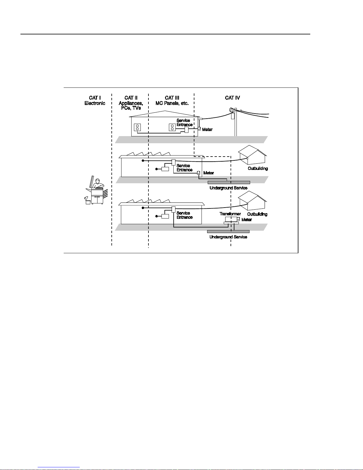
Description of IEC 61010 Measurement Categories
The IEC 61010 safety standard defines four Overvoltage (Installation) Categories (CAT I
to CAT IV) based on the magnitude of danger from transient impulses as shown in Figure
1-1.
Figure 1-1. IEC 61010 Measurement Category (CAT) Levels
The IEC 61010 Measurement CAT level indicates the level of protection the instrument
provides against impulse withstand voltage.
CAT I equipment is designed to protect against transients from high-voltage, low-energy
sources, such as electronic circuits or a copy machine.
CAT II equipment is designed to protect against transients from energy-consuming
equipment supplied from the fixed installation, such as TVs, PCs, portable tools, and
other household appliances.
CAT III equipment is designed to protect against transients in equipment in fixed
equipment installations, such as distribution panels, feeders and short branch circuits, and
lighting systems in large buildings.
CAT IV equipment is designed to protect against transients from the primary supply
level, such as an electricity meter or an overhead or underground utility service.
Organization of the Calibration Manual
This calibration manual is divided into the following chapters:
cat_levels.eps
1-8
Introduction and Specifications
Operating Instructions 1
Chapter 1 – Introduction and Specifications
This chapter introduces the Tektronix DMM4040 and 4050 Digital Multimeters,
describing their features, and accessories. This chapter also discusses use of the
Calibration Manual and the various conventions used in describing the meter’s circuitry
and presents a complete set of specifications.
Chapter 2 – General Maintenance
Chapter 2 provides maintenance information covering handling, cleaning, and fuse
replacement. Access and reassembly procedures are also explained in this chapter.
Chapter 3 – Performance Test and Calibration
This chapter provides performance verification procedures related to the specifications
presented in Chapter 1. To maintain these specifications, a full adjustment/calibration
procedure is also presented.
Operating Instructions
Full operating instructions are provided in the Tektronix DMM4040/4050 Users Manual.
Reference to these instructions may be necessary during some of the maintenance and
repair procedures presented in this Calibration Manual.
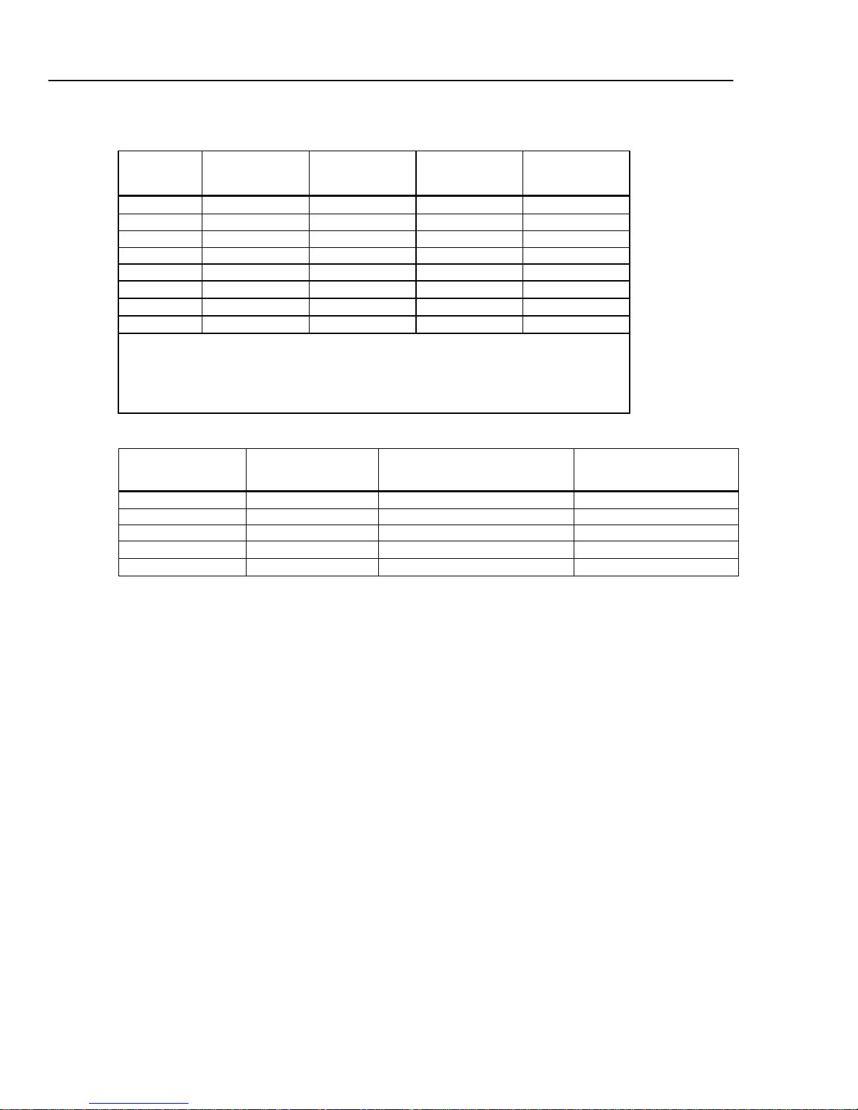
Accessories
Table 1-1 lists the available accessories for the DMM4040 and 4050.
Table 1-1. Accessories
Model / Part
Number
TL710
196-3520-00
TP750 100 Ohm RTD Temperature Probe (DMM4050 only)
013-0369-00 Calibration fixture; 4 terminal shor ting bar
Y8846S Rack Mount Kit Single
Y8846D Rackmount Kit Dual
TL705 2X4 Wire Ohm Precision Test Leads
TL725 2X4 Wire Ohm Tweezers Test Leads
159-0487-00 F2, Fuse, 440 mA, 1000 V, Fast, .406X 1.375, Bulk
159-0488-00 F1, Fuse, 11 A, 1000 V, Fast, .406INX1.5IN, Bulk
174-5813-00 USB to RS-232 cable assembly
Premium Test Lead Set
Description
012-0991-01 GPIB cable; Low EMI; 1 meter
159-0187-00 Fuse, 0.25 A, 250 V AC, slow blow
159-0063-00 Fuse, 0.125 A, 250 V, slow blow
HCTEK4321 Hard case, plastic
AC4000 Soft case, nylon
1-9

DMM4040/4050
Technical Reference Manual
General Specifications
Power
Voltage
100 V Setting ...................................................... 90 V to 110 V
120 V Setting ...................................................... 108 V to 132 V
220 V Setting ...................................................... 198 V to 242 V
240 V Setting ...................................................... 216 V to 264 V
Frequency ............................................................... 47 Hz to 440 Hz. Automatically sensed at power-on.
Power Consumption................................................ 28 VA peak (12 Watt average)
Dimensions
Height ...................................................................... 88 mm (3.46 in.)
Width ....................................................................... 217 mm (8.56 in.)
Depth ...................................................................... 297 mm (11.7 in.)
Weight ..................................................................... 3.6 kg (8.0 lb)
Shipping Weight ...................................................... 5.0 kg (11.0 lb)
Display
Vacuum Fluorescent Display, dot matrix
Environment
Temperature
Operating ............................................................ 0 °C to 55 °C
Storage ............................................................... -40 °C to 70 °C
Warm Up ............................................................. 1 hour to full uncertainty specifications
Relative Humidity (non-condensing)
Operating ............................................................ 0 °C to 28 °C <90 %
Storage ............................................................... -40 °C to 70 °C <95 %
Altitude
Operating ............................................................ 2,000 Meters
Storage ............................................................... 12,000 Meters
Vibration and Shock ................................................ Complies with MIL-PRF-28800F Class 3.
28 °C to 40 °C <80 %
40 °C to 55 °C <50 %
Triggering
Samples per Trigger ........................................... 1 to 50,000
Trigger Delay ...................................................... 0 s to 3600 s; in 10 µS increments
External Trigger Delay ........................................ <1 mS
External Trigger Jitter ......................................... <500 µS
Trigger Input ....................................................... TTL Levels
Trigger Output ..................................................... 5 V maximum (open collector)
Memory
10,000 measurements, internal, and up to 2 Gigabyte capacity with USB memory module (available separately) through
front-panel USB port
Math Functions
Zero, dBm, dB, MX+B, Offset, DCV ratio and TrendPlot, Histogram, Statistics (min/max/average/standard deviation), and
Limit Test
1-10
Introduction and Specifications
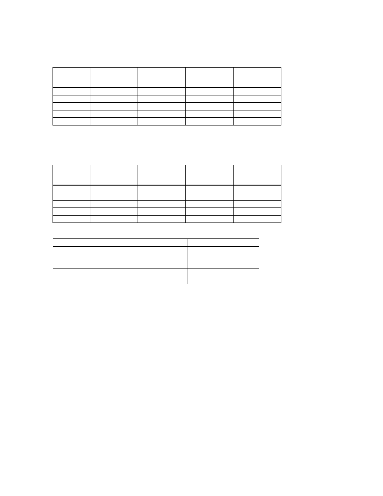
Resolution
4½ Digits
5½ Digits
6½ Digits
100 mV
100.0000 mV
10 µV
1 µV
100 nV
10 MΩ or >10 GΩ
[1]
100 µV
10 µV
1 µV
10 MΩ or >10 GΩ
[1]
10 V
10.00000 V
1 mV
[1]
100 V
100.0000 V
10 mV
1 mV
100 µV
10 MΩ ±1%
10 MΩ ±1%
Electrical Specifications 1
Electrical
Input Protection ....................................................... 1000 V all ranges
Overrange ............................................................... 20 % on all ranges except 1000 V dc, 1000 V ac
Diode, and 10 A ranges
Remote Interfaces
RS-232C, DTE 9-pin, 1200 to 230400 baud (RS-232C to USB cable available to connect the Meter to a PC USB port.
See Accessories)
IEEE 488.2
LAN and “Ethernet 10/100 base T with DHCP (for IP_ADDRess) option”
Warranty
Three years
Electrical Specifications
Accuracy specifications are valid for 6½ digit resolution mode after at least a 1-hour warm-up with Auto Zero enabled.
24-hour specifications are relative to calibration standards and assume a controlled electromagnetic environment per
EN 61326-1:2000-11
DC Voltage Specifications
Maximum Input ....................................................... 1000 V on any range
Common Mode Rejection ....................................... 140 dB at 50 or 60 Hz ±0.1 % (1 kΩ unbalance)
Normal Mode Rejection .......................................... 60 dB for NPLC of 1 or greater with analog filter off and power line
Measurement Method ............................................. Multi-ramp A/D
A/D Linearity ........................................................... 0.0002 % of measurement +0.0001 % of range
Input Bias Current ................................................... <30 pA at 25 °C
Autozero Off Operation ........................................... Following instrument warm-up at calibration temperature ±1 °C and
Analog Filter ............................................................ When using the analog filter, specifications are relative to within one
DC Ratio ................................................................. Accuracy is +/- (Input accuracy + Reference accuracy), where Input
Settling Considerations ........................................... Measurement settling times are affected by source impedance, cable
frequency ±0.1 %
100 dB for NPLC of 1 or greater with analog filter on and power line
frequency ±0.1 %
less than 10 minutes, add error: 0.0002 % range additional error
+5 µV.
hour of using the ZERO function for that range and NPLC setting.
accuracy = DC Voltage accuracy for the HI to LO Input (in ppm of the
Input voltage), and Reference accuracy = DC Voltage accuracy for the
HI to LO (Sense) Reference (in ppm of the Reference voltage).
dielectric characteristics, and input signal changes.
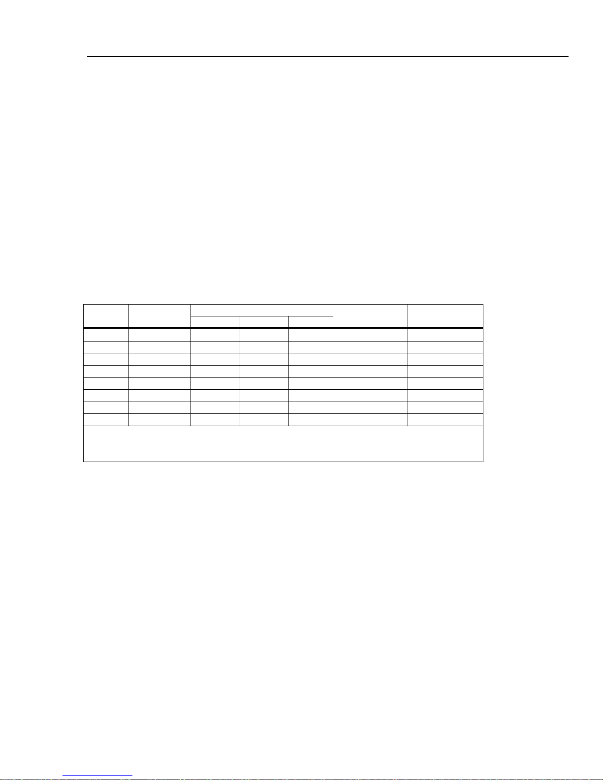
Input Characteristics
Range Resolution
1 V 1.000000 V
1000 V 1,000.000 V 100 mV 10 mV 1 mV
[1] Inputs beyond ±14 V are clamped through 200 kΩ typical. 10 MΩ is default input impedance.
1-11
Input Impedance
100 µV 10 µV 10 MΩ or >10 GΩ
DMM4040/4050
±1 °
±5 °
±5 °
Temperature
Outside 18 to 28 °C
100 mV
0.0025 + 0.003
0.0025 + 0.0035
0.0037 + 0.0035
0.0005 + 0.0005
1 V
0.0018 + 0.0006
0.0018 + 0.0007
0.0025 + 0.0007
0.0005 + 0.0001
10 V
0.0013 + 0.0004
0.0018 + 0.0005
0.0024 + 0.0005
0.0005 + 0.0001
100 V
0.0018 + 0.0006
0.0027 + 0.0006
0.0038 + 0.0006
0.0005 + 0.0001
1000 V
0.0018 + 0.0006
0.0031 + 0.001
0.0041 + 0.001
0.0005 + 0.0001
±1 °
±5 °
±5 °
Temperature
Outside 18 to 28 °C
100 mV
0.003 + 0.003
0.004 + 0.0035
0.005 + 0.0035
0.0005 + 0.0005
1 V
0.002 + 0.0006
0.003 + 0.0007
0.004 + 0.0007
0.0005 + 0.0001
10 V
0.0015 + 0.0004
0.002 + 0.0005
0.0035 + 0.0005
0.0005 + 0.0001
100 V
0.002 + 0.0006
0.0035 + 0.0006
0.0045 + 0.0006
0.0005 + 0.0001
1000 V
0.002 + 0.0006
0.0035 + 0.0010
0.0045 + 0.0010
0.0005 + 0.0001
Digits
NPLC
Additional NPLC Noise Error
6½
100
0 % of range
5½
1
0.001 % of range
5½
.2
4½
0.02
0.017 % of range +17 µV
Technical Reference Manual
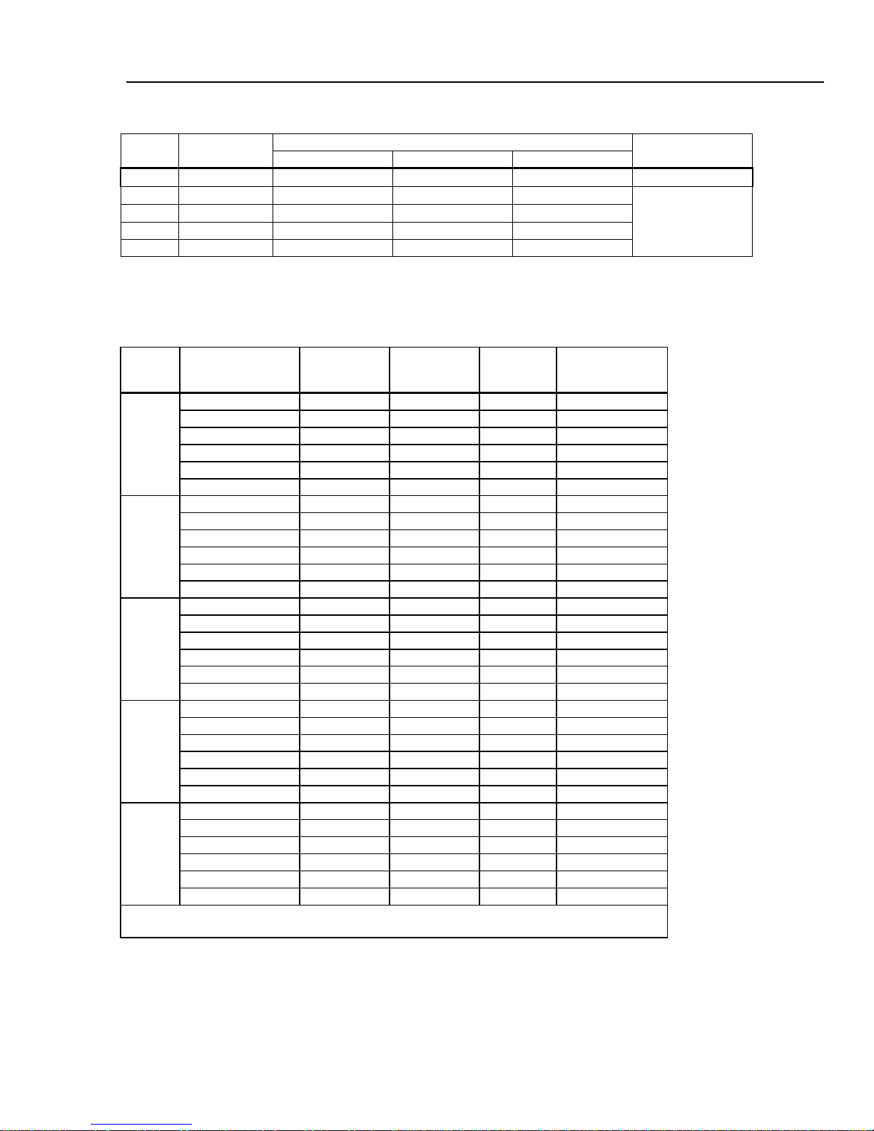
4050 Accuracy
Accuracy is given as ± (% measurement + % of range)
Range
24 Hour
(23
C)
90 Days
(23
C)
4040 Accuracy
Accuracy is given as ± (% measurement + % of range)
Range
24 Hour
(23
C)
90 Days
(23
C)
Additional Errors
1 Year
(23
1 Year
(23
C)
C)
Coefficient/ °C
Coefficient/ °C
6½ 10 0 % of range
0.0025 % of range +12 µV
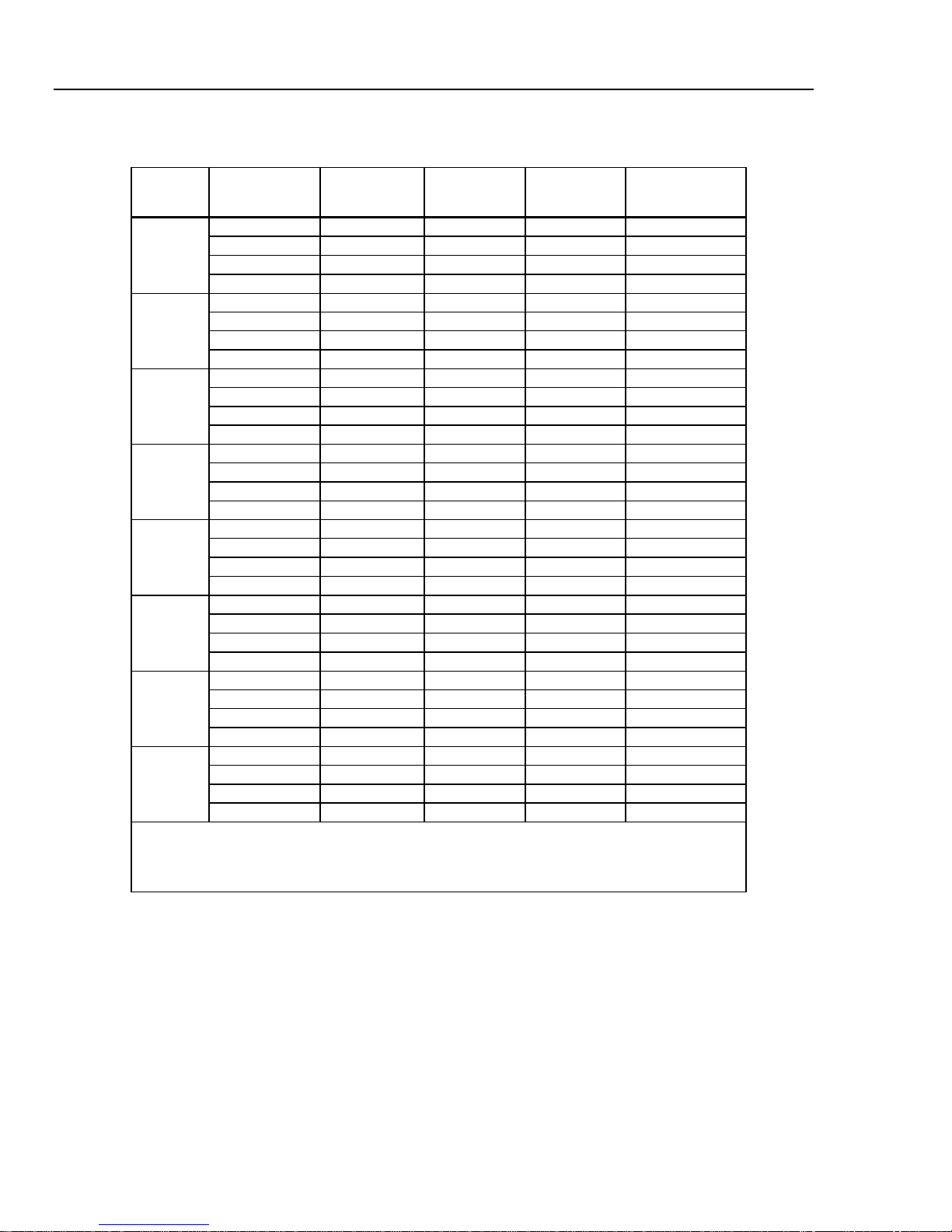
AC Voltage Specifications
AC Voltage specifications are for ac sinewave signals >5 % of range. For inputs from 1 % to 5 % of range and <50 kHz,
add an additional error of 0.1 % of range, and for 50 kHz to 100 kHz, add 0.13 % of range.
Maximum Input ....................................................... 1000 V rms or 1414 V peak or 8 x 10
less) for any range.
Measurement Method ............................................. AC-coupled true-rms. Measures the ac component of input with up to
1000 V dc bias on any range.
AC Filter Bandwidth:
Slow .................................................................... 3 Hz – 300 kHz
Medium ............................................................... 20 Hz – 300 kHz
Fast ..................................................................... 200 Hz – 300 kHz
Common Mode Rejection ....................................... 70 dB at 50 Hz or 60 Hz ±0.1 % (1 kΩ unbalance)
Crest Factor Error (applies to non-sinusoidal waveforms only)
Maximum Crest Factor ....................................... 5:1 at Full Scale
Additional Crest Factor Errors (<100 Hz) ............ Crest factor 1-2, 0.05 % of full scale
Crest factor 2-3, 0.2 % of full scale
Crest factor 3-4, 0.4 % of full scale
Crest factor 4-5, 0.5 % of full scale
7
volts-Hertz product (whichever is
1-12
Introduction and Specifications
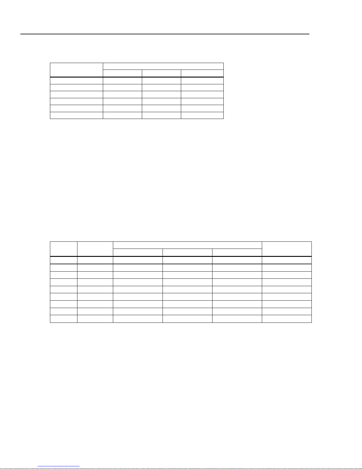
Resolution
4½ Digits
5½ Digits
6½ Digits
100 mV
100.0000 mV
10 µV
1 µV
100 nV
1 V
1.000000 V
100 µV
10 µV
1 µV
10 V
10.00000 V
1 mV
100 µV
1000 V
1,000.000 V
100 mV
10 mV
1 mV
±1 °
±5 °
±5 °
Temperature
Outside 18 to 28 °C
100 mV
3 – 5 Hz
1.0 + 0.03
1.0 + 0.04
1.0 + 0.04
0.1 + 0.004
5 – 10 Hz
0.35 + 0.03
0.35 + 0.04
0.35 + 0.04
0.035 + 0.004
100 – 300 kHz
[1]
4.0 + 0.50
4.0 + 0.50
4.0 + 0.50
0.20 + 0.02
3 – 5 Hz
1.0 + 0.02
1.0 + 0.03
1.0 + 0.03
0.1 + 0.003
5 – 10 Hz
0.35 + 0.02
0.35 + 0.03
0.35 + 0.03
0.035 + 0.003
10 Hz – 20 kHz
0.04 + 0.02
0.05 + 0.03
0.06 + 0.03
0.005 + 0.003
20 – 50 kHz
0.1 + 0.04
0.11 + 0.05
0.12 + 0.05
0.011 + 0.005
50 – 100 kHz
0.55 + 0.08
0.6 + 0.08
0.6 + 0.08
0.06 + 0.008
100 – 300 kHz
[1]
4.0 + 0.50
4.0 + 0.50
4.0 + 0.50
0.2 + 0.02
10 V
3 – 5 Hz
1.0 + 0.02
1.0 + 0.03
1.0 + 0.03
0.1 + 0.003
5 – 10 Hz
0.35 + 0.02
0.35 + 0.03
0.35 + 0.03
0.035 + 0.003
10 Hz – 20 kHz
0.04 + 0.02
0.05 + 0.03
0.06 + 0.03
0.005 + 0.003
20 – 50 kHz
0.1 + 0.04
0.11 + 0.05
0.12 + 0.05
0.011 + 0.005
50 – 100 kHz
0.55 + 0.08
0.6 + 0.08
0.6 + 0.08
0.06 + 0.008
100 – 300 kHz
[1]
4.0 + 0.50
4.0 + 0.50
4.0 + 0.50
0.2 + 0.02
100 V
3 – 5 Hz
1.0 + 0.02
1.0 + 0.03
1.0 + 0.03
0.1 + 0.003
5 – 10 Hz
0.35 + 0.02
0.35 + 0.03
0.35 + 0.03
0.035 + 0.003
10 Hz – 20 kHz
0.04 + 0.02
0.05 + 0.03
0.06 + 0.03
0.005 + 0.003
[1]
5 – 10 Hz
0.35 + 0.015
0.35 + 0.0225
0.35 + 0.0225
0.035 + 0.00225
10 Hz – 20 kHz
0.04 + 0.015
0.05 + 0.0225
0.06 + 0.0225
0.005 + 0.00225
20 – 50 kHz
0.1 + 0.03
0.11 + 0.0375
0.12 + 0.0375
0.011 + 0.00375
50 – 100 kHz
[2]
0.55 + 0.06
0.6 + 0.06
0.6 + 0.06
0.06 + 0.006
100 – 300 kHz
[1][2]
4.0 + 0.375
4.0 + 0.375
4.0 + 0.375
0.2 + 0.015
[2] 1000 Volt range is limited to 8 X 10⁷ volt-Hertz
Electrical Specifications 1
Input Characteristics
Range Resolution
100 µV 10 µV
100 V 100.0000 V 10 mV 1 mV
4040/4050 Accuracy
Accuracy is given as ± (% measurement + % of range)
Range Frequency
10 Hz – 20 kHz 0.04 + 0.03 0.05 + 0.04 0.06 + 0.04 0.005 + 0.004
20 – 50 kHz 0.1 + 0.05 0.11 + 0.05 0.12 + 0.05 0.011 + 0.005
50 – 100 kHz 0.55 + 0.08 0.6 + 0.08 0.6 + 0.08 0.06 + 0.008
1 V
24 Hour
(23
C)
90 Days
(23
C)
1 Year
(23
C)
Input Impedance
1 MΩ ±2 % shunted
by <100 pf
Coefficient/ °C
20 – 50 kHz 0.1 + 0.04 0.11 + 0.05 0.12 + 0.05 0.011 + 0.005
50 – 100 kHz 0.55 + 0.08 0.6 + 0.08 0.6 + 0.08 0.06 + 0.008
100 –- 300 kHz
1000 V 3 – 5 Hz 1.0 + 0.015 1.0 + 0.0225 1.0 + 0.0225 0.1 + 0.00225
[1] Typically 30 % reading error at 1 MHz
4.0 + 0.50 4.0 + 0.50 4.0 + 0.50 0.2 + 0.02
1-13
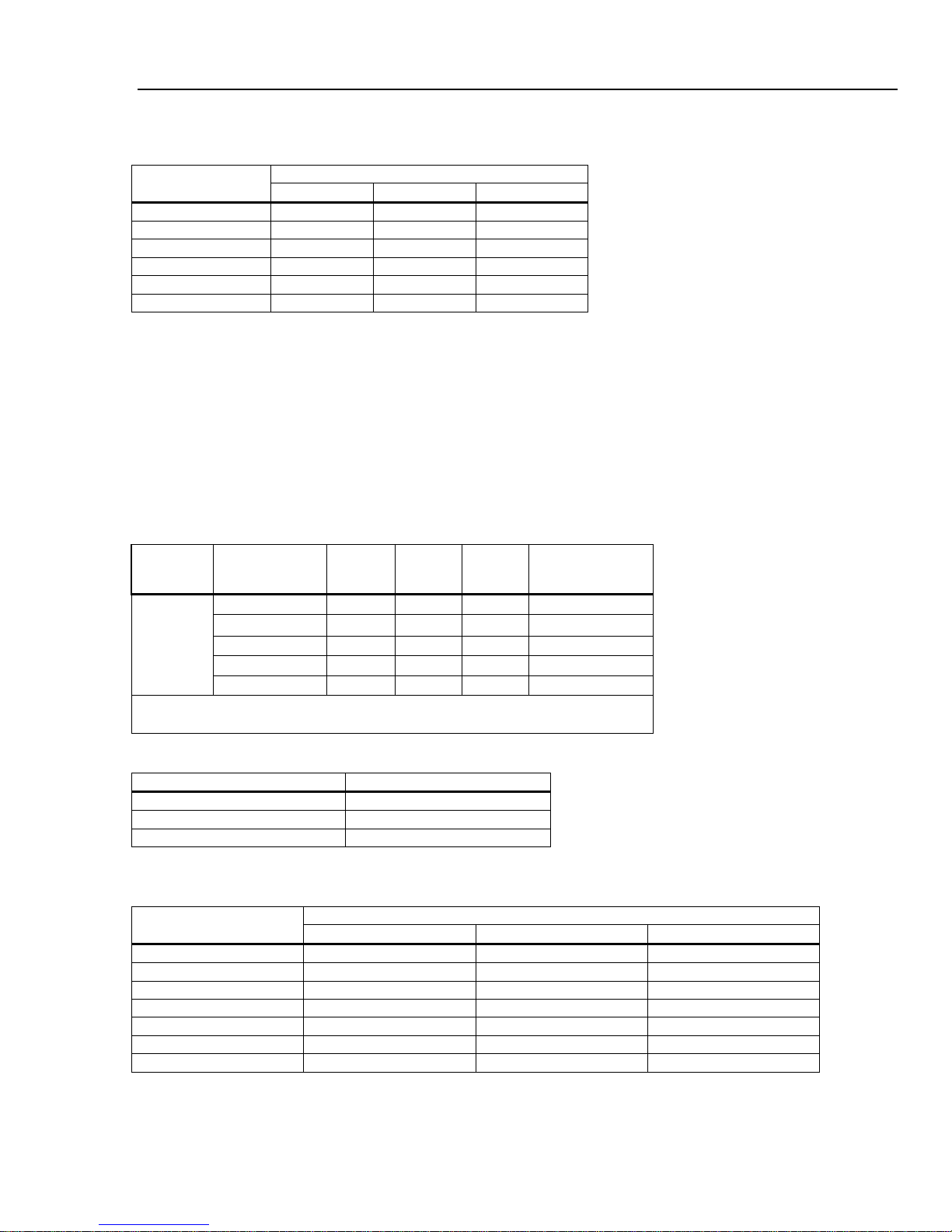
DMM4040/4050
AC Filter
3 HZ (slow)
20 HZ (medium)
200 HZ (fast)
20 – 40 Hz
0
0.02 – 40 – 100 Hz
0
0.01
0.55
200 Hz – 1 kHz
0 0 0.02
>1 kHz
0 0 0
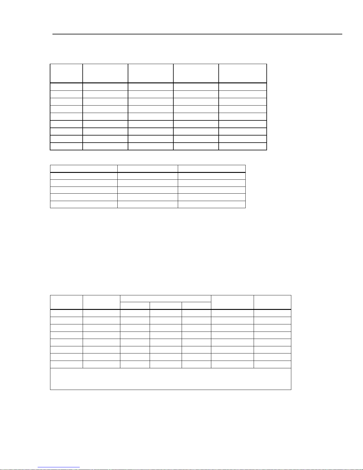
Resolution
4½ Digits
5½ Digits
6½ Digits
10 Ω
10.00000 Ω
1 mΩ
100 µΩ
10 µΩ
100 Ω
100.0000 Ω
10 mΩ
1 mΩ
100 µΩ
1 kΩ
1.000000 kΩ
100 mΩ
10 mΩ
1 mΩ
10 kΩ
10.00000 kΩ
1 Ω
100 mΩ
10 mΩ
100 µA/6 V
1 MΩ
1.000000 MΩ
100 Ω
10 Ω
1 Ω
10 µA/13 V
10 MΩ
10.00000 MΩ
1 kΩ
100 Ω
10 Ω
1 µA/13 V
1.0 GΩ
1.000000 GΩ
100 kΩ
10 kΩ
1 kΩ
1 µA || 10 MΩ/10 V
Technical Reference Manual
Additional Low Frequency Errors
Error is stated as % of reading.
Frequency
10 – 20 Hz 0 0.25 –
100 – 200 Hz 0 0 0.2
Resistance
Specifications are for 4-wire resistance function, 2 x 4-wire resistance, or 2-wire resistance with zero. If zero is not used,
add 0.2 Ω for 2-wire resistance plus lead resistance, and add 20 mΩ for 2 x 4-wire resistance function.
Measurement Method ............................................. Current source referenced to LO input
Max. Lead Resistance (4-wire ohms) ..................... 10 % of range per lead for 10 Ω, 100 Ω, 1 kΩ ranges. 1 kΩ per lead on
Input Protection ....................................................... 1000 V on all ranges
Common Mode Rejection ....................................... 140 dB at 50 or 60 Hz ±0.1 % (1 kΩ unbalance)
Normal Mode Rejection .......................................... 60 dB for NPLC of 1 or greater with analog filter off and power line
Analog Filter ............................................................ When using the analog filter, specifications are relative to within one
all other ranges
frequency ±0.1 %
100 dB for NPLC of 1 or greater with analog filter on and power line
frequency ±0.1 %
hour of using the ZERO function for that range and NPLC setting.
Input Characteristics
Range Resolution
100 kΩ 100.0000 kΩ 10 Ω 1 Ω 100 mΩ 100 µA/13 V
100 MΩ 100.0000 MΩ 10 kΩ 1 kΩ 100 Ω 1 µA || 10 MΩ/10 V
Source Current
5 mA/13 V
1 mA/6 V
1 mA/6 V
1-14
Introduction and Specifications
±1 °
±5 °
±5 °
Temperature
Outside 18 to 28 °C
10 Ω
0.003 + 0.01
0.008 + 0.03
0.01+ 0.03
0.0006 + 0.0005
100 Ω
0.003 + 0.003
0.008 + 0.004
0.01 + 0.004
0.0006 + 0.0005
1 kΩ
0.002 + 0.0005
0.008 + 0.001
0.01 + 0.001
0.0006 + 0.0001
100 kΩ
0.002 + 0.0005
0.008 + 0.001
0.01 + 0.001
0.0006 + 0.0001
10 MΩ
0.015 + 0.001
0.02 + 0.001
0.04 + 0.001
0.003 + 0.0004
1 GΩ
1.0 + 0.01
1.5 + 0.01
2.0 + 0.01
0.6 + 0.0002
Digits
NPLC
Additional NPLC Noise Error
6½
100
0 % of range
6½
10
0 % of range
5½
0.2
0.003 % of range ±7 mΩ
0.017 % of range ±15 mΩ
Resolution
Shunt Resistance
4½ Digits
5½ Digits
6½ Digits
10 nA
1 nA
100 pA
100 Ω
10 mA
10.00000 mA
1 µA
100 nA
10 nA
1 Ω
<0.025 V
100 mA
100.0000 mA
100 nA
<0.25 V
400 mA
[3]
400.000 mA
100 µA
10 µA
1 µA
1 Ω
<0.50 V
[2]
100 µA
10 µA
1 µA
0.01 Ω
[1]
3.00000A
1 mA
<0.15 V
10 A
10.00000 A
1 mA
100 µA
10 µA
0.01 Ω
<0.5 V
Electrical Specifications 1
4040/4050 Accuracy
Accuracy is given as ± (% measurement + % of range)
Range
10 kΩ 0.002 + 0.0005 0.008 + 0.001 0.01 + 0.001 0.0006 + 0.0001
1 MΩ 0.002 + 0.001 0.008 + 0.001 0.01 + 0.001 0.001 + 0.0002
100 MΩ 0.3 + 0.01 0.8 + 0.01 0.8 + 0.01 0.15 + 0.0002
24 Hour
(23
C)
90 Days
(23
C)
1 Year
(23
C)
Coefficient/ °C
Additional Ohms Errors
5½ 1 0.001 % of range
4½ 0.02
DC Current
Input Protection ....................................................... Tool-accessible 11 A/1000 V and 440 mA/1000 V fuses, limits of
Common Mode Rejection ....................................... 140 dB at 50 or 60 Hz ±0.1 % (1 kΩ unbalance)
Normal Mode Rejection .......................................... 60 dB for NPLC of 1 or greater with analog filter off and power line
Analog Filter ............................................................ When using the analog filter, specifications are relative to within one
400 mA continuous 550 mA for 2 minutes on, 1 minute off.
frequency ±0.1 %
100 dB for NPLC of 1 or greater with analog filter on and power line
frequency ±0.1 %
hour of using the ZERO function for that range and NPLC setting.
Input Characteristics
Range Resolution
100 µA 100.0000 µA
1 mA 1.000000 mA 100 nA 10 nA 1 nA
1 A
1.000000 A
3 A
[1] Part of 10 A range.
[2] Available on the front panel terminal only.
[3] 400 mA continuously; 550 mA for 2 minutes on, 1 minute off.
1-15
10 µA 1 µA
100 µA 10 µA 0.01 Ω
(Ohms)
100 Ω
1 Ω
Burden Voltage
<0.015 V
<0.15 V
<0.05 V
DMM4040/4050
±1 °
±5 °
±5 °
Temperature
Outside 18 to 28 °C
100 µA
[4]
0.01 + 0.02
0.04 + 0.025
0.05 + 0.025
0.002 + 0.003
1 mA
0.007 + 0.005
0.030 + 0.005
0.05 + 0.005
0.002 + 0.0005
10 mA
[4]
0.007 + 0.02
0.03 + 0.02
0.05 + 0.02
0.002 + 0.002
100 mA
0.01 + 0.004
0.03 + 0.005
0.05 + 0.005
0.002 + 0.0005
[3]
1 A
[2]
0.03 + 0.02
0.04 + 0.02
0.05 + 0.02
0.005 + 0.001
[1][2]
10 A
[2]
0.1 + 0.008
0.12 + 0.008
0.15 + 0.008
0.005 + 0.0008
Additional NPLC Noise Error for
10 A
Additional NPLC Noise Error
6½
100
0 % of range
0 % of range
6½
10
0 % of range
0 % of range
5½
0.2
0.011 % of range ±4 µA
0.11 % of range ±4 µA
0.04 % of range ±4 µA
0.28 % of range ±4 µA
Technical Reference Manual
Accuracy (4040/4050)
Accuracy is given as ± (% measurement + % of range)
Range
400 mA
3 A
0.03 + 0.004 0.04 + 0.005 0.05 + 0.005 0.005 + 0.0005
0.05 + 0.02 0.08 + 0.02 0.1 + 0.02 0.005 + 0.002
[1] Part of 10 A range
[2] Available at front panel connectors only
[3] 400 mA continuously; 550 mA for 2 minutes on, 1 minute off.
[4] In RF fields of 3 V/m and frequencies of 1.7 GHz to 1.9 GHz, add 0.06% of range. With conducted RF
voltages of 3 Vrms and frequencies of 20 MHz to 50 MHz, add 0.08% of range.
24 Hour
(23
C)
90 Days
(23
C)
1 Year
(23
C)
Coefficient/ °C
Additional Current Errors
Digits NPLC
5½ 1 0.001 % of range 0.01 % of range
4½ 0.02
1 mA, 100 mA, 400 mA, 3 A an d
for 100 µA, 10 mA, 1 A
1-16
Introduction and Specifications
Resolution
4½ Digits
5½ Digits
6½ Digits
100 µA
100.0000 µA
10 nA
1 nA
100 pA
100 Ω
<0.015 V
1 mA
100 Ω
10 mA
10.00000 mA
1 µA
100 nA
10 nA
1 Ω
<0.025 V
100.0000 mA
10 µA
1 µA
100 nA
1 Ω
<0.25 V
[3]
100 µA
10 µA
1 µA
1 Ω
1 A
[2]
1.000000 A
100 µA
10 µA
1 µA
0.01 Ω
<0.05 V
[1][2]
3.00000 A
1 mA
<0.05 V
[2]
100 µA
10 µA
0.01 Ω
Electrical Specifications 1
AC Current
The following ac current specifications are for sinusoidal signals with amplitudes greater than 5 % of range. For inputs
from 1 % to 5 % of range, add an additional error of 0.1 % of range.
Input Protection ....................................................... Tool accessible 11 A/1000 V and 440 mA/1000 V fuses, limits of
Measurement Method ............................................. ac-coupled true-rms, dc-coupled to the fuse and shunt (no blocking
AC Filter Bandwidth
Slow .................................................................... 3 Hz to 10 kHz
Medium ............................................................... 20 Hz to 10 kHz
Fast ..................................................................... 200 Hz to 10 kHz
Crest Factor Error (applies to non-sinusoidal waveforms only)
Maximum Crest Factor ....................................... 5:1 at full scale
Additional Crest Factor Errors (<100 Hz) ............ Crest factor 1-2, 0.05 % of full scale
400 mA continuous 550 mA for 2 minutes on, 1 minute off.
capacitor)
Crest factor 2-3, 0.2 % of full scale
Crest factor 3-4, 0.4 % of full scale
Crest factor 4-5, 0.5 % of full scale
Input Characteristics
Range Resolution
Shunt Resistance
(Ohms)
Burden Voltage
1.000000 mA 100 nA 10 nA 1 nA
100 mA
400 mA
400.000 mA
3 A
10 A
10.00000 A 1 mA
[1] Part of 10 A range
[2] Available at front panel connectors only
[3] 400 mA continuously; 550 mA for 2 minutes on, 1 minute off; maximum crest factor 3:1 at 400 mA
100 µA 10 µA 0.01 Ω
<0.15 V
<0.50 V
<0.5 V
1-17
DMM4040/4050
±1 °
±5 °
±5 °
Temperature
Outside 18 to 28 °C
3 – 5 Hz
1.1 + 0.06
1.1 + 0.06
1.1 + 0.06
0.2 + 0.006
5 – 10 Hz
0.35 + 0.06
0.35 + 0.06
0.35 + 0.06
0.1 + 0.006
5 – 10 kHz
0.35 + 0.7
0.35 + 0.7
0.35 + 0.7
0.03 + 0.006
1 mA
3 – 5 Hz
1.0 + 0.04
1.0 + 0.04
1.0 + 0.04
0.1 + 0.006
5 – 10 Hz
0.3 + 0.04
0.3 + 0.04
0.3 + 0.04
0.035 + 0.006
10 Hz – 5 kHz
0.1 + 0.04
0.1 + 0.04
0.1 + 0.04
0.015 + 0.006
5 – 10 kHz
0.2 + 0.25
0.2 + 0.25
0.2 + 0.25
0.03 + 0.006
10 mA
3 – 5 Hz
1.1 + 0.06
1.1 + 0.06
1.1 + 0.06
0.2 + 0.006
10 Hz – 5 kHz
0.15 + 0.06
0.15 + 0.06
0.15+ 0.06
0.015 + 0.006
5 – 10 kHz
0.35 + 0.7
0.35 + 0.7
0.35 + 0.7
0.03 + 0.006
100 mA
3 – 5 Hz
1.0 + 0.04
1.0 + 0.04
1.0 + 0.04
0.1 + 0.006
5 – 10 Hz
0.3 + 0.04
0.3 + 0.04
0.3 + 0.04
0.035 + 0.006
10 Hz – 5 kHz
0.1 + 0.04
0.1 + 0.04
0.1 + 0.04
0.015 + 0.006
[3]
3 – 5 Hz
1.0 + 0.1
1.0 + 0.1
1.0 + 0.1
0.1 + 0.006
10 Hz – 1 kHz
0.1 + 0.1
0.1 + 0.1
0.1 + 0.1
0.015 + 0.006
1kHz – 10 kHz
0.2 + 0.7
0.2 + 0.7
0.2 + 0.7
0.03 + 0.006
[2]
3 – 5 Hz
1.0 + 0.04
1.0 + 0.04
1.0 + 0.04
0.1 + 0.006
5 – 10 Hz
0.3 + 0.04
0.3 + 0.04
0.3 + 0.04
0.035 + 0.006
5 – 10 kHz
0.35 + 0.7
0.35 + 0.7
0.35 + 0.7
0.03 + 0.006
3 A
[1][2]
3 – 5 Hz
1.1 + 0.06
1.1 + 0.06
1.1 + 0.06
0.1 + 0.006
5 – 10 Hz
0.35 + 0.06
0.35 + 0.06
0.35 + 0.06
0.035 + 0.006
10 Hz – 5 kHz
0.15 + 0.06
0.15 + 0.06
0.15 + 0.06
0.015 + 0.006
5 – 10 kHz
0.35 + 0.7
0.35 + 0.7
0.35 + 0.7
0.03 + 0.006
[2]
3 – 5 Hz
1.1 + 0.06
1.1 + 0.06
1.1 + 0.06
0.1 + 0.006
10 Hz – 5 kHz
0.15 + 0.06
0.15 + 0.06
0.15 + 0.06
0.015 + 0.006
5 – 10 kHz
0.35 + 0.7
0.35 + 0.7
0.35 + 0.7
0.03 + 0.006
Technical Reference Manual
4040/4050 Accuracy
Accuracy is given as ± (% measurement + % of range)
Range
100 µA
400 mA
1 A
Frequency
(Hz)
24 Hour
(23
C)
90 Days
(23
C)
1 Year
(23
C)
Coefficient/ °C
10 Hz – 5 kHz 0.15 + 0.06 0.15 + 0.06 0.15 + 0.06 0.015 + 0.006
5 – 10 Hz 0.35 + 0.06 0.35 + 0.06 0.35 + 0.06 0.1 + 0.006
5 – 10 kHz 0.2 + 0.25 0.2 + 0.25 0.2 + 0.25 0.03 + 0.006
5 – 10 Hz 0.3 + 0.1 0.3 + 0.1 0.3 + 0.1 0.035 + 0.006
10 Hz – 5 kHz 0.1 + 0.04 0.1 + 0.04 0.1 + 0.04 0.015 + 0.006
10 A
5 – 10 Hz 0.35 + 0.06 0.35 + 0.06 0.35 + 0.06 0.035 + 0.006
[1] Part of 10 A range
[2] Available only on front panel connectors
[3] 400 mA continuously; 550 mA for 2 minutes on, 1 minute off; maximum crest factor 3:1 at 400 mA; specification for
current above 329 mA is typical.
1-18
Introduction and Specifications
AC Filter
3HZ (slow)
20HZ (medium)
200HZ (fast)
20 – 40 Hz
0
0.02 – 40 – 100 Hz
0
0.01
0.55
200 Hz – 1 kHz
0 0 0.02
> 1 kHz
0 0 0
±1 °
±5 °
±5 °
Temperature
Outside 18 to 28 °C
100 mV to
3 – 5 Hz
0.1
0.1
0.1
0.005
5 – 10 Hz
0.05
0.05
0.05
0.005
10 – 40 Hz
0.03
0.03
0.03
0.001
40 Hz – 300 kHz
0.006
0.01
0.01
0.001
300 kHz – 1 MHz
0.006
0.01
0.01
0.001
Gate Time
Resolution
0.01
5½
0.1
6½
1.0
6½
Resolution
6½
5½
4½
5 – 10 Hz 0 0.17
0.17
10 – 40 Hz 0 0.2
0.2
40 – 100 Hz 0 0.06
0.21
100 – 300 Hz 0 0.03
0.21
300 Hz – 1 kHz 0 0.01
0.07
> 1 kHz 0 0
0.02
Electrical Specifications 1
Additional Low Frequency Errors
Error is stated as % of reading.
Frequency
10 – 20 Hz 0 0.25 –
100 – 200 Hz 0 0 0.2
Frequency
Gate Times ............................................................. Programmable to 1 s, 100 ms, and 10 ms
Measurement Method ............................................. Flexible counting technique. AC-coupled input using the ac voltage
Settling Considerations ........................................... When measuring frequency or period after a dc offset voltage change,
Measurement Considerations ................................. To minimize measurement errors, shield inputs from external noise
measurement function.
errors may occur. For the most accurate measurement, wait up to
1 second for the input blocking capacitor to settle.
when measuring low-voltage, low-frequency signals.
4040/4050 Accuracy
Accuracy is given as ± % measurement
Range Frequency
[1][2]
1000 V
[1] Input >100 mV. For 10 – 100 mV, multiply percent measurement error by 10.
[2] Limited to 8 X 10
7
volt-Hertz
24 Hour
(23
C)
90 Days
(23
C)
1 Year
(23
Coefficient/ °C
C)
Gate Time vs. Resolution
Additional Low Frequency Errors
Error stated as percent of measurement for inputs >100 mV. For 10 – 100 mV, multiply percent by 10.
Frequency
3 – 5 Hz 0 0.12 0.12
1-19
DMM4040/4050
[1]
(23 ±5 °C)
°C
Outside 18 to 28 °C
2% ± 2.5 %
10 nF
10 pF
0.05 + 0.01
1% ± 0.5 %
1 nF
0.01 + 0.01
10 µF
1% ± 0.5 %
100 µF
100 nF
1% ± 0.5 %
0.01 + 0.01
1 mF
1 µF
1% ± 0.5 %
0.01 + 0.01
10 mF
10 µF
1% ± 0.5 %
0.01 + 0.01
100 mF
100 µF
4% ± 0.2 %
0.05 + 0.05
Accuracy
Temperature
°
90 Days
(23 ±5 °C)
1 Year
(23 ±5 °C)
-200 °C
0.001 °C
0.06
0.09
0.0025
0 °C
0.001 °C
0.04
0.06
0.002
100 °C
0.001 °C
0.05
0.08
0.002
600 °C
0.001 °C
0.18
0.22
0.002
Digits
NPLC
Additional NPLC Noise Error
6 ½
100
6 ½
10
0 °C
0.03 °C
5 ½
0.2
0.12 °C
4 ½
0.02
±1 °
±5 °
±5 °
Temperature
Outside 18 to 28 °C
1000.0 Ω
0.002 + 0.01
0.008 + 0.02
0.01 + 0.02
0.001 + 0.002
Technical Reference Manual
Capacitance (4050 only)
Accuracy is stated as ±(% of measurement + % of range)
Range Resolution
1 Year Accuracy
Temperature Coefficient/
1 nF 1 pF
100 nF 100 pF
1 µF
10 nF
[1] Stated accuracy is attained when Zero function is used.
1% ± 0.5 %
1% ± 0.5 %
0.05 + 0.05
0.01 + 0.01
0.01 + 0.01
Temperature (4050 only)
Test Current ............................................................ 1 mA
Accuracy is stated as ± °C and is based on a Platinum RT100 (DIN IEC 751, 385 type) RTD with less than 10 ohms lead
resistance. The accuracy listed in the table below are valid only when using the 4-wire RTD measurement function.
Specifications do not include probe accuracy, which must be added.
Range Resolution
-100 °C 0.001 °C 0.05 0.08 0.002
Coefficient/ °C
Outside 18 to 28
C
300 °C 0.001 °C 0.1 0.12 0.002
Additional Errors
0 °C
5 ½ 1
0.6 °C
Continuity
Continuity Threshold ............................................... Selectable between 1 Ω and 1000 Ω
Test Current ............................................................ 1 mA
Response Time ....................................................... 300 samples/sec with audible tone
Accuracy is given as ± (% measurements + % of range)
Range
24 Hour
(23
C)
90 Days
(23
C)
1 Year
(23
C)
Coefficient/ °C
1-20

Introduction and Specifications
±1 °
±5 °
±5 °
Temperature
Outside 18 to 28 °C
10.0000 V
0.002 + 0.001
0.008 + 0.002
0.01 + 0.002
0.001 + 0.002
Measurements/Second
[1]
4040
4050
DC Volts, DC Current, and
6½
100 NPLC
1.67 (2) s
0.6 (0.5)
0.6 (0.5)
6½
10 NPLC
167 (200) ms
6 (5)
6 (5)
5½
1 NPLC
16.7 (20) ms
60 (50)
60 (50)
5½
0.2 NPLC
3.3 ms
270
270
4½
0.02 NPLC
500 us
995
995
[2]
6½
3 Hz 0.47
0.47
6½
20 Hz 1.64
1.64
6½
200 Hz
[3]
4.5
4.5
5½
100 ms 9.8
9.8
4½
10 ms 80
80
Capacitance
6½
NA
2
Measurement Uncertainty 1
Diode Test
Test Current ............................................................ 100 µA or 1 mA
Response Time ....................................................... 300 samples/sec with audible tone.
Accuracy is given as ± (% measurements + % of range)
Range
5.0000 V 0.002 + 0.002 0.008 + 0.002 0.01 + 0.002 0.001 + 0.002
24 Hour
(23
C)
90 Days
(23
C)
1 Year
(23
C)
Coefficient/ °C
Measurement Rates (IEEE488[4])
Function Digits Setting
Resistance
AC Voltage and AC Current
Frequency and Period 6½ 1 s 1 1
[1] Typical measurement rates with auto-zero off, delay = 0, display off, auto range off and math off.
[2] Maximum measurement rates for 0.01 % of ac step. Wh en dc input varies, additional settling delay is required.
[3] For remote operation or external trigger using default settling delay
[4] Speeds available in OutG SW 1.0.700.18 or higher. Note that the measurements rates for RS232 can vary depending on the
baud rate chosen. If the baud rate selected is 115,200, the maximum measurement rate is 711 measurement/s. The LAN bus
has a maximum measurement rate of 963 measurement/s.
Integration Time
60 Hz (50 Hz)
Measurement Uncertainty
The Meter's measurement uncertainties are expressed in the form ( % of reading + % of
range ). In addition to the reading error and range error, you may need to add additional
errors for certain operating conditions. If the Meter is operated outside the temperature
range specified, an additional temperature coefficient error must be applied. For dc
voltage, dc current, and resistance measurements, apply an additional reading-speed
error. For ac voltage and ac current measurements, apply an additional low frequency
error or crest factor error.
The "% of reading" error varies according to the input level on the selected range. This
error is expressed in percent of input measurement. The “% of range” error represents the
floor noise of the range and represents the lowest meaningful resolution for that range.
The following example shows the reading error applied to the Meter's 24-hour 10 Vdc
specification: 0.0013% of input + 0.0004% of range.
Assuming the Meter is set to the 10V range with an input voltage of 1 V, the
measurement uncertainty would be: +/- [(0.0013% x 1V) + (.0004% x 10V)].
Permissible High Value = 1 + 0.000053V = 1.000053 V
Permissible Low Value = 1 - 0.000053V = 0.999947 V
1-21

DMM4040/4050
Technical Reference Manual
Interpreting Accuracy Specifications
The following sections provide a clearer understanding of specifications over time and
with temperature variations.
24
-Hour Accuracy
The 24
measurement range for short time intervals and within a stable environment. Short
accuracy is usually specified for a 24
90
-Day and 1-Year Accuracy
The longer
±5 °C temperature range. These specifications include the initial calibration errors plus
the Meter's long
Temperature Coefficients
Accuracy is usually specified at the calibration temperature (T
range. This is a common temperature range for many operating environments. Add
additional temperature coefficient errors to the accuracy specification if the Meter is
operated outside the ±5 °C temperature range (the specification is per °C).
-hour accuracy specification indicates the Meter's relative accuracy over its full
-term
-hour period and for a ±1 °C temperature range.
duration accuracy specifications are valid at the calibration temperature (Tcal)
-term drift errors.
cal) ±5 °C temperature
Configuring for Highest Accuracy Measurements
The measurement configurations shown below assume that the Meter is in its power-on
or reset state. It is also assumed that auto-ranging is enabled to ensure proper full-scale
range selection.
DC Voltage, DC Current, and Resistance Measurements
Select NPLC and 100 (NPLCs) for highest instrument resolution and accuracy.
For the best dc voltage accuracy, set INPUT HIGH INPUT Z (impedance) to GOhm (for
the 100 mV, 1 V, and 10 V ranges).
For the best resistance measurement accuracy, use the 4
For 2
-wire ohms, dc voltage and dc current measurements, set AUTOZERO to ON to
remove thermal EMF and offset errors.
Zero the test lead resistance for 2
-wire and 4-wire ohms measurements and zero to
remove any interconnection offset for dc voltage measurements.
AC Voltage and AC Current Measurements:
Set the AC FILTER to 3 Hz: SLOW.
Frequency and Period Measurements:
Set the GATE TIME to 1 sec.
-wire ohms function (4W).
1-22

Chapter 2
General Maintenance
Title Page
Introduction .......................................................................................................... 2-3
Warranty Repairs and Shipping Information ....................................................... 2-3
General Maintenance Information ....................................................................... 2-3
Required Equipment ........................................................................................ 2-3
Power Requirements ........................................................................................ 2-3
Static Safe Handling ........................................................................................ 2-3
Cleaning ............................................................................................................... 2-4
Fuse Replacement ................................................................................................ 2-4
Line-Power Fuse .............................................................................................. 2-4
Current-Input Fuses ......................................................................................... 2-5
If the Meter Does Not Turn On ............................................................................ 2-7
Display Tests ........................................................................................................ 2-7
Disassembly Procedures ...................................................................................... 2-7
General Disassembly ....................................................................................... 2-7
Main Chassis Disassembly .............................................................................. 2-8
Front Panel Disassembly ................................................................................. 2-8
Assembly Procedures ........................................................................................... 2-8
2-1

DMM4040/4050
Technical Reference Manual
2-2

General Maintenance
Introduction 2
Introduction
This chapter provides handling, cleaning, fuse replacement, disassembly, and assembly
instructions for the Meter.
Warranty Repairs and Shipping Information
If your meter is still under warranty, see the warranty information at the front of this
manual for instructions on returning the unit. A Tektronix telephone number and the
website address can be found in the “Contacting Tektronix” section at the front of this
manual.
General Maintenance Information
The following sections describe how to maintain the Meter.
Required Equipment
Equipment required for calibration, troubleshooting, and repair of the Meter is listed in
Table 3-1.
Power Requirements
To avoid electric shock, connect the Meter’s power cord to a
power receptacle with earth ground.
The Meter operates on power distribution standards found throughout the world, and
must be set up to operate on the correct line voltage power it. The Meter is packed ready
for use with a line voltage determined at the time of ordering. If the selected line voltage
does not match the power the Meter will be plugged into, then the Meter’s line voltage
setting must be changed and the line fuse possibly replaced. See the DMM4040 and 4050
Safety and Installation Manual for information on switching the Meter’s line voltage.
If you have not already done so, plug the line cord into the connector on the rear of the
Meter.
Static Safe Handling
All integrated circuits, including surface mounted ICs, are susceptible to damage from
electrostatic discharge (ESD). Modern integrated circuit assemblies are more susceptible
to damage from ESD than ever before.
Integrated circuits today can be built with circuit lines less than one micron thick,
allowing more than a million transistors on a 1/4-inch square chip. These submicron
structures are sensitive to static voltages under 100 volts. This much voltage can be
generated on a dry day by simply moving your arm. A person can develop a charge of
2,000 volts by walking across a vinyl tile floor, and polyester clothing can easily generate
5,000 to 15,000 volts during movement against the wearer. These low voltage static
problems are often undetected, because a static charge must be in the 30,000 to 40,000
volt range before a person will feel a shock.
Warning
Most electronic components manufactured today can be degraded or destroyed by ESD.
While protection networks are used in CMOS devices, they can only reduce, not
eliminate, component susceptibility to ESD.
2-3

DMM4040/4050
Technical Reference Manual
ESD may not cause an immediate failure in a component; a delayed failure or
"wounding" effect is caused when the semiconductor’s insulation layers or junctions are
punctured. The static problem is thus complicated in that failure may occur anywhere
from two hours to six months after the initial damage.
Two failure modes are associated with ESD. First, a person who has acquired a static
charge can touch a component or assembly and cause a transient discharge to pass
through the device. The resulting current ruptures the junctions of a semiconductor. The
second failure mode does not require contact with another object. Simply exposing a
device to the electric field surrounding a charged object can destroy or degrade a
component. MOS devices can fail when exposed to static fields as low as 30 volts.
Observe the following rules for handling static-sensitive devices:
1. Handle all static-sensitive components in a static-safe work area.
Use grounded static-control table mats on all repair benches, and always wear a
grounded wrist strap. Handle boards by their nonconductive edges only. Store plastic,
vinyl, and Styrofoam objects outside the work area.
2. Store and transport all static-sensitive components and assemblies in static shielding
bags or containers.
Static-shielding bags and containers protect components and assemblies from direct static
discharge and external static fields. Store components in their original packages until they
are ready for use.
Cleaning
To avoid electric shock or damage to the Meter, never get water
inside the meter.
To avoid damaging the Meter’s housing, do not apply solvents
to the Meter.
If the Meter requires cleaning, wipe it down with a cloth lightly dampened with water or
a mild detergent. Do not use aromatic hydrocarbons, chlorinated solvents, or methanolbased fluids to wipe down the meter.
Fuse Replacement
The Meter employs fuses to protect both the line-power and current measurement inputs.
Line-Power Fuse
The Meter has a line-power fuse in series with the power supply. Table 2-1 indicates the
proper fuse for each of the four line voltage selections. This fuse is located on the rear
panel.
Warning
Caution
To replace this fuse:
1. Unplug the power cord from the Meter and remove any test leads.
2. Remove the fuse holder by inserting a small screwdriver blade in the narrow recess to
the left of the fuse holder and pry to the right until the holder pops out, as shown in
2-4

General Maintenance
Fuse Replacement 2
Figure 2-1. The Meter is shipped with a replacement fuse of the same rating as the
fuse installed in the fuse block.
3. Remove the fuse and replace with one rated appropriately for the selected line-power
voltage. See Table 2-1 for fuse ratings with specific line voltage.
4. Replace the selector block back into the fuse holder.
Warning
To avoid electric shock or fire, do not use makeshift fuses or
short-circuit the fuse holder. Use only Tektronix fuses.
Table 2-1. Line Voltage to Fuse Rating
Line Voltage Selection Fuse Rating Tektronix Part No.
100 / 120 0.25 A, 250 V (slow blow) 159-0187-00
220 / 240 0.125 A, 250 V (slow blow) 159-0063-00
Current-Input Fuses
The 100 mA and 10 A inputs are protected by user-replaceable fuses.
• The 100 mA input is protected by a fuse (A1F2) rated at 440 mA, 1000 V (fast
blow), 10,000 A minimum breaking capacity.
• The 10 A input is protected by a fuse (A1F1) rated at 11 A, 1000 V (fast blow),
10,000 A minimum breaking capacity.
For protection against fire or arc flash, replace a blown fuse
only with one from Tektronix.
2-5
Figure 2-1. Line Fuse Replacement
Warning
caw0201f.eps
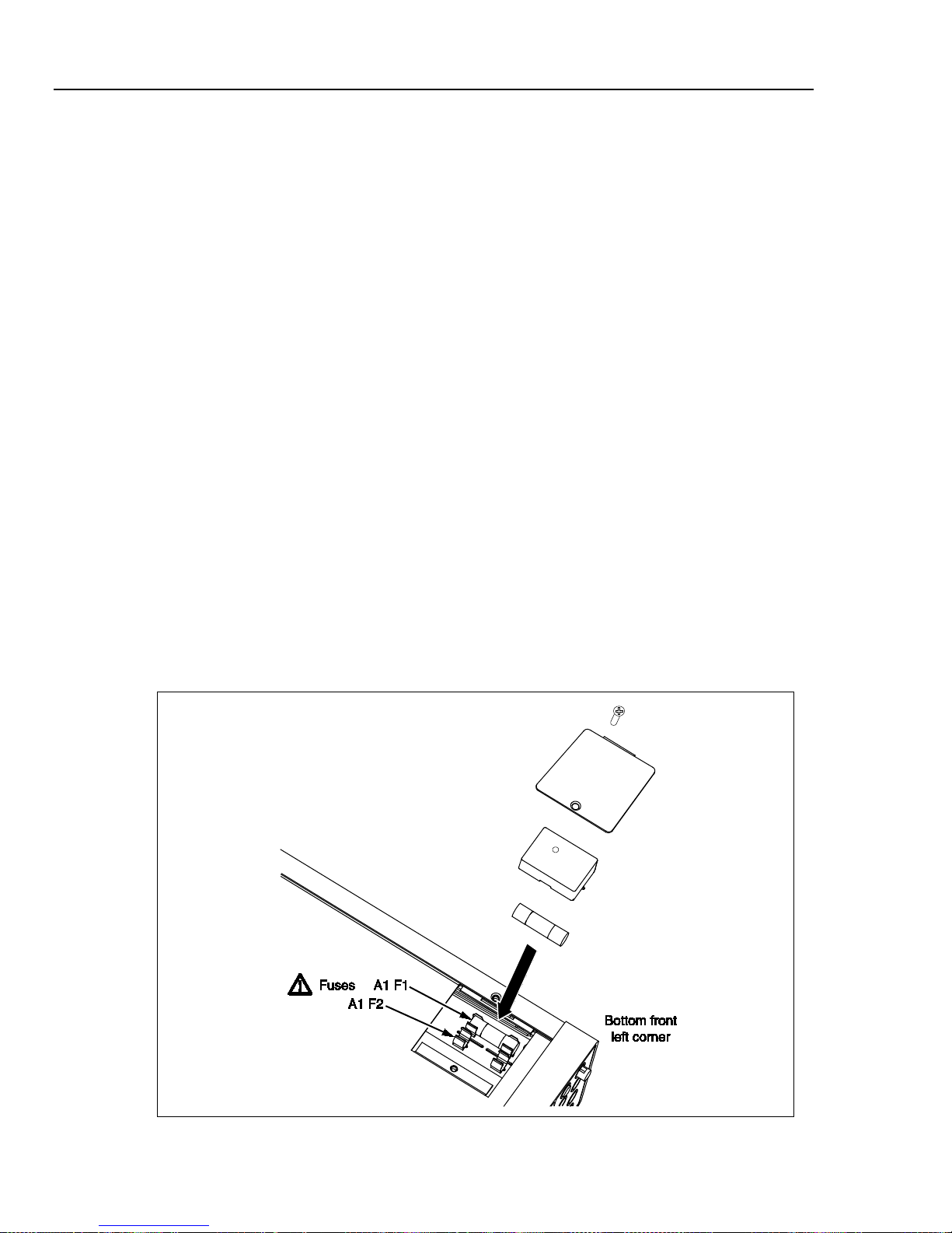
DMM4040/4050
Technical Reference Manual
To test for a blown Current Input fuse:
1. With the Meter powered up, plug a test lead into the VΩ connector.
2. Remove the probe from the 100 mA connector and insert into the 10 A
To replace the Current Input fuses:
1. Turn the Meter off, unplug the power cord from the Meter, and remove all test
2. Turn the Meter on its back.
3. Unscrew the retaining screw on the fuse access door, as depicted in Figure 2-2.
4. Remove the protective cover from the fuse holders by slightly depressing the
If the fuse is good, the Meter will read less than 200 Ω. If the fuse is blown, the
Meter will read
.
connector.
If the fuse is good, the Meter will read less than 1 Ω. If the fuse is blown, the
Meter will read
.
leads.
back edge of the cover to unlatch it from the printed circuit board. Pull up on the
back edge of the cover and remove it from the fuse compartment.
5. Remove the defective fuse and replace with one having the appropriate rating
(See table 4-1 for fuse ratings and Tektronix part numbers).
6. Replace the protective cover by pushing it over the fuses while aligning the
catches with the holes in the printed circuit board. Press the cover down until the
catches engage the printed circuit board.
7. Replace the fuse door and secure it by tightening the retaining screw.
2-6
Figure 2-2. Current Input Fuse Replacement
caw020.eps

General Maintenance
If the Meter Does Not Turn On 2
If the Meter Does Not Turn On
Use the following steps to help solve problems encountered when turning on the Meter.
1. Verify the Meter’s power switch is in the “On” position.
2. Make sure that the power cord is firmly plugged into the power module on the rear of
the Meter.
3. Make sure the power source the Meter is plugged into is energized.
4. Ensure the Meter’s power line voltage is set to the proper value for your country. See
the “Fuse Replacement” section earlier in this chapter for instructions on changing
the Meter’s voltage setting.
5. Verify that the power-line fuse is good.
If these steps don’t solve the problem, then contact Tektronix for more help. See the
“Contacting Tektronix” section in the front of this manual for contact information.
Display Tests
To test the pixels on the front panel display, use the following steps.
1. Press .
2. Press the SYSTEM softkey.
3. Press the DISPLAY softkey.
All pixels of the display should be illuminated.
Disassembly Procedures
To avoid electric shock, disconnect the Meter from power
before removing the cover.
Only qualified service personnel should attempt servicing this
Meter.
To disassemble the Meter, a #2 Phillips screwdriver and small crescent wrench are
required. There are three sets of disassembly instructions: general, main chassis, and front
panel.
General Disassembly
To disassemble the Meter:
1. Turn off the power by turning off the mains power at the rear of the Meter and
removing the power cord. The front panel power key only puts the Meter in a powersave mode and does not remove mains power from the Meter.
Warning
2. Remove all cables from the Meter.
3. Remove the Meter bumpers by pulling from a corner and stretching the bumpers off
the Meter.
4. Remove the bail by rotating the handle upright to a 90° angle from the top of the
Meter and pull bail out from the sides of the Meter.
5. Remove the top cover by removing the four screws on the bottom of the chassis, and
slide the cover towards the back of the Meter.
2-7

DMM4040/4050
Technical Reference Manual
6. Remove the wedges from the front and rear input modules by rotating the top toward
the chassis middle and pulling up. See Figure 4-1.
7. Remove both sets of screws holding the front panel to the chassis (8-32 pan head and
6-32 flat head undercut). See Figure 4-1.
8. Gently remove the front panel by pulling it forward and set it aside.
9. Remove the plastic handle caps from the chassis sides by rotating the front slightly
inward and pulling forward.
Main Chassis Disassembly
To disassemble the Meter’s main chassis:
1. Carefully remove the transformer connectors from the main board.
2. Carefully remove the screws that hold the transformer and its bracket to the chassis
while holding the transformer so that it cannot drop on the circuits.
3. Carefully lift the transformer out of the chassis and place the transformer behind the
instrument with the power module leads still attached.
4. Remove the jackscrews for the RS-232 and IEEE488 connectors to the chassis.
5. Remove the screws holding the main circuit board to the chassis (three 6-32 pan-head
screws).
6. Remove the main circuit board.
Front Panel Disassembly
To disassemble the Meter’s front panel:
1. Remove the one 6-32 pan head and two 6-32 flat head undercut screws holding the
display shield to the rest of the front panel assembly and remove the shield.
2. Remove the thread-forming screw holding the front panel shield to the front panel
and remove the shield.
3. Remove the three thread-forming screws from the keypad assembly and remove
display module.
Assembly Procedures
To assemble the three parts of the Meter, follow the disassembly instructions in reverse
order.
2-8

Chapter 3
Performance Test and Calibration
Title Page
Introduction .......................................................................................................... 3-3
Required Equipment ............................................................................................ 3-3
Test Considerations .............................................................................................. 3-5
Performance Tests ................................................................................................ 3-5
Volts DC Verification ...................................................................................... 3-5
Volts DC Ratio Verification ............................................................................ 3-9
Volts AC and Frequency Verification ............................................................. 3-11
4-Wire Ohms Verification ............................................................................... 3-14
2-Wire Ohms Verification ............................................................................... 3-16
2X4 Test Lead Verification Steps ................................................................... 3-17
Rear Panel Terminal Verification Steps .......................................................... 3-18
Capacitance Verification Steps (DMM4050 only) .......................................... 3-20
DC Current Verification Steps ........................................................................ 3-22
AC Current Verification Steps ........................................................................ 3-24
Adjustment (Calibration) ..................................................................................... 3-26
Unlocking the Meter for Adjustments (Calibration) ....................................... 3-26
Unlocking the Meter for Adjustments Over a Remote Interface ..................... 3-26
Changing the Calibration Password ................................................................ 3-26
Resetting the Calibration Password ................................................................. 3-27
Changing the Calibration Date ........................................................................ 3-28
Equipment for Calibration ............................................................................... 3-28
Adjustment Process ......................................................................................... 3-28
Aborting a Calibration Process ........................................................................ 3-34
Sample Adjustment Program ........................................................................... 3-34
3-1

DMM4040/4050
Technical Reference Manual
3-2

Performance Test and Calibration
Introduction 3
Introduction
This chapter of the Calibration Manual provides performance tests to verify the Meter is
operating within published specifications as well as a complete calibration procedure.
The performance test and, if necessary, the calibration procedure can be performed both
periodically and after service or repair.
The performance tests can be used as an acceptance test upon receipt of the Meter. Use
the 90-day specifications when performing an acceptance test after performing a
calibration.
Required Equipment
Table 3-1 lists the equipment required for performance testing and calibration of the
Meter.
Table 3-1. Required Test Equipment
Function Instrument Type Model Comments
Volts dc Standard Fluke 5520A Must be characterized with 8508A
8½ digit meter Fluke 8508A Used to characterize the 5520A
4-wire short Tektronix low thermal 4-
wire short or equivalent
Alternate standard
Volts ac Standard Fluke 5520A Must be characterized with 8508A
8½ digit meter Fluke 8508A Used to characterize the 5520A.
4-wire short Tektronix low thermal 4-
Alternate standard
Frequency Standard Fluke 5520A
Alternate standard Fluke 5520A with any
Alternate standard Function generator Specifications include 0.075 %
[1]
Fluke 5720A
wire short or equivalent
[1]
Fluke 5720A
scope option
Tektronix PN 013-0369-00
Note: TURs <4:1 at 1 V, 10 V, and
100 V at 20 kHz
Tektronix PN 013-0369-00
frequency accuracy from 3 – 40 Hz
and 0.0025 % accuracy for
frequencies up to 1 MHz
3-3

DMM4040/4050
Technical Reference Manual
Function Instrument Type Model Comments
Ohms Standard Fluke 5520A Must be characterized with 8508A
8½ digit meter Fluke 8508A Used to characterize the 5520A
Table 3-1. Required Test Equipment (cont.)
4-wire short Tektronix low thermal 4-
Tektronix PN 013-0369-00
wire short or equivalent
Alternate standard Fluke 5720A or equivalent
Alternate standard
[1]
resistor
Fluke 8508A-7000K
1 Gohm resistor or
equivalent (better than
Used for calibrating/verifying 1 GΩ
range when a 5520A is not
available.
±0.35 % maximum
uncertainty)
Capacitance
(DMM4050
only)
Standard Fluke 5520A TURS <4:1 at 1 nF, 10 nF, 100 µF,
1 mF, and 10 mF.
Alternate standards 1 nF, 10 nF, 100 nF, 1 µF,
10 µF, 100 µF, 1 mF,
Standards must be ±0.25 % and
rated for at least 5 V
10 mF, and 100 mF
standards
Current dc Standard Fluke 5520A Must be characterized with 8508A
8½ digit meter Fluke 8508A Only used to characterize the
5520A
Alternate standard
[1]
Fluke 5720A with Fluke
Note: TUR <4 at 10 A
5725A
Current ac Standard Fluke 5520A Must be characterized with 8508A
3-4
8½ digit meter Fluke 8508A Only used to characterize the
5520A or 5720A
Alternate standard
[1]
Fluke 5720A with Fluke
5725A
TUR at 1 A at 5 kHz < 4:1. Must
characterize with 8508A at 100 µA
at 5 kHz. 100 µA, 1 mA, 10 mA, 100
mA, 1 A and 2 A at 10 kHz.
Cables To r educe the possibility of inducing errors with ac signals picked up by the test leads,
use short, shielded twisted-pair PTFE-ins ulated test cables between the test equipment
and the Meter. Fluke makes a 2 foot (P N 738716) and 4 foot (PN 738724) PTFE
insulated test cable for this purpose.
Tektronix USB to RS232 cable (PN 174-5813-00) or Tektronix IEEE 488 cable (1 meter,
PN 012-0991-01)
[1] Other alternate standards beside those listed can be used as long as they provide sufficient traceable [Test uncertaintity
Ratios(TURs)) at each calibration and verification point.

Performance Test and Calibration
Test Considerations 3
Test Considerations
For optimum performance, all test procedures should comply with the following
recommendations:
• Assure the calibration ambient temperature (T
28 °C. Ideally the calibration should be performed at 23 °C ±2 °C.
• Assure ambient relative humidity is less than 80%.
• Allow a 60-minute warm-up period.
• Use shielded twisted-pair PTFE-insulated cables to reduce settling and noise
errors.
• Keep all input cables as short as possible.
• Ensure that the calibration standards and test procedures used do not introduce
additional errors.
Ideally, the standards used to verify and adjust the Meter should be four
times more accurate than each full-scale error specification of the Mete r.
• Use Tektronix’s low thermal 4-Wire short for all voltages and ohmic shorts. See
Table 3-1 for the Tektronix’ part number.
Performance Tests
The following performance tests are provided to ensure that the Meter is in proper
operating condition. If the Meter fails any of the performance tests, calibration
adjustment and/or repair is needed. The performance test works best if executed in the
sequence shown in Table 3-2.
cal) is stable and between 18 °C and
Note
Each of the measurements listed in the following tests assumes the Meter is being tested
after a one-hour warm-up in an environment with an ambient temperature of 18 to 28 ºC
and a relative humidity of less than 80%.
All instrument settings for verification use power up conditions except as
noted by the verification step.
Volts DC Verification
Connect the Meter to the test equipment as shown in Figure 3-1 and, depending on which
meter you are calibrating, apply the voltages listed in Table 3-2 or Table 3-3. Some
verification test steps are firmware dependant. To determine the firmware revision of the
UUT:
1. Press ,
2. Press the softkey labeled System.
3. Press the softkey labeled Version.
Note the OutG SW value.
Verification forms can be found in Appendix A which can be copied and used to record
each meter reading.
Note
3-5

DMM4040/4050
Technical Reference Manual
For the zero (0) V tests, use the 4-wire short to short the Hi/Lo and Sense
inputs.
Note
Figure 3-1. DC Volts Test Equipment Setup with 5520A
3-6
gdc023.eps

Performance Test and Calibration
Performance Tests 3
Table 3-2. DMM4050 DC Volts Verification Steps
Nominal
Input (V)
Range
90-day Test Limits 1-year Test Limits
High Low High Low
0 0.100 3.5 µV -3.5 µV 3.5 µV -3.5 µV
100.0 mV
-100.0 mV
[1]
0.100 100.006 mV 99.994 mV 100.0072 mV 99.9928 mV
[1]
0.100 -99.994 Mv -100.006 mV -99.9928 mV -100.0072 mV
0 V 1 7.0 µV -7.0 µV 7.0 µV -7.0 µV
[1]
1 V
1 1.000025 V 0.999975 V 1.000032 V 0.999968 V
[1]
-1 V
1 -0.999975 V -1.000025 V -0.999968 V -1.000032 V
0 V 10 50.0 µV -50.0 µV 50.0 µV -50.0 µV
[1]
5 V
10 5.000140 V 4.999860 V 5.000170 V 4.999830 V
[1]
-5 V
10 -4.999860 V -5.000140 V -4.999830 V -5.000170 V
[1]
10 V
10 10.000230 V 9.999770 V 10.000290 V 9.999710 V
[1]
-10 V
10 -9.999770 V -10.000230 V -9.999710 V -10.000290 V
0 V 100
[1]
100 V
100 100.0033 V 99.9967 V 100.0044 V 99.9956 V
[1]
-100 V
100 -99.9967 V -100.0033 V -99.9956 V -100.0044 V
600.0 µV -600.0 µV 600.0 µV -600.0 µV
0 V 1000 10.0 mV -10.0 mV 10.0 mV -10.0 mV
[1]
1 kV
1000 1000.0410 V 999.9590 V 1000.0510 V 999.9490 V
[1]
-1 kV
1000 -999.9590 V -1000.0410 V -999.9490 V -1000.0510 V
[1] 5520A must be used with 8508A to obtain suitable test uncertainty ratio.
3-7

DMM4040/4050
Technical Reference Manual
Table 3-3. DMM4040 DC Volts Verification Steps
Nominal
Input (V)
0 V
100.0 mV
-100.0 mV
0 V
[1]
1 V
[1]
-1 V
0 V
[1]
5 V
[1]
-5 V
[1]
10 V
-10 V
0 V
100 V
-100 V
0 V
1 kV
-1 kV
Range
0.100
[1]
[1]
0.100
0.100
1
1
1
10
10
10
10
10
100
100
100
1000
1000
1000
90-day Test Limits 1-year Test Limits
High Low High Low
3.5 µV -3.5 µV 3.5 µV -3.5 µV
100.0075 mV 99.9925 mV 100.0085 mV 99.9915 mV
-99.9925 mV -100.0075 mV -99.9915 mV -100.0085 mV
7.0 µV -7.0 µV 7.0 µV -7.0 µV
1.000037 V 999.963 mV 1.000047 V 999.953 mV
-999.963 mV -1.000037 V -999.953 mV -1.000047 V
50.0 µV -50.0 µV 50.0 µV -50.0 µV
5.00015 V 4.99985 V 5.000225 V 4.999775 V
-4.99985 V -5.00015 V -4.999775 V -5.000225 V
10.00025 V 9.99975 V 10.0004 V 9.9996 V
-9.99975 V -10.00025 V -9.9996 V -10.0004 V
600.0 µV -600.0 µV 600.0 µV -600.0 µV
100.0041 V 99.9959 V 100.0051 V 99.9949 V
-99.9959 V -100.0041 V -99.9949 V -100.0051 V
10.0 mV -10.0 mV 10.0 mV -10.0 mV
1.000045 kV 999.955E+0 1.000055 kV 999.945 V
-999.955 V -1.000045 kV -999.945 V -1.000055 kV
[1] 5520A must be used with 8508A to obtain suitable test uncertainty ratio.
3-8

Performance Test and Calibration
Performance Tests 3
Volts DC Ratio Verification
Connect the Meter to the test equipment as shown in Figure 3-2 and depending on which
meter you are calibrating, apply the voltages listed in Table 3-4 or Table 3-5. Verification
forms can be found in Appendix A which can be copied and used to record each meter
reading.
Note
Note that the Ratio function is only available in Outguard SW version 2.0
and later.
Figure 3-2. DC Volts Ratio Test Equipment Setup with 5520A and 5720A
3-9
gdc037.eps

DMM4040/4050
Technical Reference Manual
Nominal
Input (V)
[2]
100 mV
1 V
-10 V 10 V 1.000046 V 0.999954 V 1.000058 V 0.999942 V
[1] Using 5520A output to the Hi/Lo and Sense Hi/Lo terminals.
[2] Optional test.
100 mV
1 V
-10 V 10 V 1.00005 V 0.99995 V 1.00008 V 0.99992 V
0.100 V 1.00012 V 0.99988 V 1.000144 V 0.999856 V
[2]
1 V 1.00005 V 0.99995 V 1.000064 V 0.999936 V
Nominal
Input (V)
[2]
0.100 V 1.00015 V 0.99985 V 1.00017 V 0.99983 V
[2]
1 V 1.000074 V 0.999926 V 1.000094 V 0.999906 V
Table 3-4. DMM4050 DC Volts Ratio Verification Steps
90-day Test Limits 1-year Test Li mits
Range
High Low High Low
Table 3-5. DMM4040 DC Volts Ratio Verification Steps
90-day Test Limits 1-year Test Li mits
Range
High Low High Low
[1]
[1]
[1] Using 5520A output to the Hi/Lo and Sense Hi/Lo terminals.
[2] Optional test.
3-10

Performance Test and Calibration
Performance Tests 3
Volts AC and Frequency Verification
Connect the Meter to the test equipment as shown in Figure 3-3 and, depending on which
meter you are calibrating, apply the voltage listed in Table 3-6. Verification forms can be
found in Appendix A which can be copied and used to record each meter reading.
Figure 3-3. AC Volts Test Equipment Setup with 5520A
3-11
gdc024.eps

DMM4040/4050
Technical Reference Manual
Table 3-6. DMM4040/4050 AC Volts Veri fication Steps
Nominal Input
90-day Test Limits 1-year Test Limits
Range
Ampl. Freq. High Low High Low
100.0 mV
[1]
10 Hz 0.100 100.09 mV 99.91 mV 100.1 mV 99.9 mV
100.0 mV 20 kHz 0.100 100.09 mV 99.91 mV 100.1 mV 99.9 mV
100.0 mV 50 kHz 0.100 100.16 mV 99.84 mV 100.17 mV 99.83 mV
100.0 mV 100 kHz 0.100 100.68 mV 99.32 mV 100.68 mV 99.32 mV
100.0 mV 300 kHz 0.100 104.5 mV 95.5 mV 104.5 mV 95.5 mV
[1]
1 V
10 Hz 1 1.0008 V 999.2 mV 1.0009 V 999.1 mV
1 V 20 kHz 1 1. 0008 V 999. 2 mV 1.0009 V 999. 1 mV
1 V 50 kHz 1 1. 0016 V 998. 4 mV 1.0017 V 998. 3 mV
1 V 100 kHz 1 1.0068 V 993.2 mV 1.0068 V 993.2 mV
1 V 300 kHz 1 1.045 V 955.0 mV 1.045 V 955.0 mV
[1]
10 V
10 Hz 10 10.008 V 9.992 V 10.009 V 9.991 V
[1]
10 V
20 kHz 10 10.008 V 9.992 V 10.009 V 9.991 V
10 V 50 kHz 10 10.016 V 9.984 V 10.017 V 9.983 V
10 V 100 kHz 10 10.068 V 9.932 V 10.068 V 9.932 V
3 V 300 kHz 10 3.17 V 2.83 V 3.17 V 2.83 V
100 V 45 Hz 100 100.08 V 99.92 V 100.09 V 99.91 V
[1]
100 V
20 kHz 100 100.08 V 99.92 V 100.09 V 99.91 V
100 V 50 kHz 100 100.16 V 99.84 V 100.17 V 99. 83 V
[1]
100 V
100 kHz 100 100.68 V 99.32 V 100.68 V 99.32 V
1000 V 45 Hz 1000 1000.800 999.200 1.0009 kV 999.1 V
1000 V 1 kHz 1000 1000.800 999.200 1.0009 kV 999.1 V
[1]
1000 V
10 kHz 1000 1000.800 999.200 1.0009 kV 999.1 V
320 V 20 kHz 1000 320.460 319.540 320.492 V 319.508 V
320 V 50 kHz 1000 320.852 V 319.148 V 320.884 V 319.116 V
320 V 100 kHz 1000 322.72 V 317.2 8 V 322.72 V 317.28 V
[1] 5520A must be used with 8508A to obtain suitable test uncertainty ratio.
3-12

Performance Test and Calibration
Performance Tests 3
Table 3-7. DMM4040/4050 AC Volts F requency Verification Steps
Nominal Input 90-day T est Limits 1-year Test Limits
Ampl. Freq. High Low High Low
1 V 10 Hz 10.00300 Hz 9.99700 Hz 10.00300 Hz 9.99700 Hz
1 V 40 Hz 40.0040 Hz 39.9960 Hz 40.00400 Hz 39.9960 Hz
100 mV 300 kHz 300.030 kHz 29.99700 kHz 300.0300 kHz 29.99700 kHz
100 mV 1 MHz 1.000100 MHz 999.9000 kHz 1.0001000 MHz 999.9000 kHz
3-13

DMM4040/4050
Technical Reference Manual
4-Wire Ohms Verification
Connect the Meter to the test equipment as shown in Figure 3-4 and, depending on which
meter you are calibrating, apply the resistance listed in Table 3-8. Verification forms can
be found in Appendix A which can be copied and used to record each meter reading.
For zero (0) ohms tests, use the 4-wire short to short the Hi/Lo and Sense
inputs.
Note
Figure 3-4. 4-Wire Ohms Test Equipment Setup
3-14
gdc025.eps

Performance Test and Calibration
Performance Tests 3
Table 3-8. DMM4040/4050 4-Wire Ohms V erification Steps
Nominal
Input
[1]
0 Ω
10 3.0 mΩ 0 Ω 3.0 mΩ 0 Ω
[1]
10 Ω
10 10.00380 Ω 9.99620 Ω 10.00400 Ω 9.99600 Ω
[2]
0 Ω
100 4.0 mΩ 0 Ω 4.0 mΩ 0 Ω
[1]
100 Ω
100 100.0120 Ω 99.9880 Ω 100.01400 Ω 99.98600 Ω
Range
90-day Test Limits 1-year Test Limits
High Low High Low
0 Ω 1000 10.0 mΩ 0 Ω 10.0 mΩ 0 Ω
1 kΩ 1000 1000.090 Ω 999.910 1.00011000 kΩ 999.89000
0 Ω 10000 100.0 mΩ 0 Ω 100.0 mΩ 0 Ω
10 kΩ 10000 10.00090 kΩ 9999.10 1.000110 kΩ 9998.90
0 Ω 100000 1.000000 0 Ω 1.000000 0 Ω
100 kΩ 100000 100.0090 kΩ 99991.0 10.00110 kΩ 99989.0
[1] 5520A must be used with 8508A to obtain suitable test uncertainty ratio.
3-15

DMM4040/4050
Technical Reference Manual
2-Wire Ohms Verification
Connect the Meter to the test equipment as shown in Figure 3-5 and, depending on which
meter you are calibrating, apply the resistance listed in Table 3-9. Verification forms can
be found in Appendix A which can be copied and used to record each meter reading.
For zero (0) ohms tests, use the 4-wire short to short the Hi/Lo and Sense
inputs.
Note
Figure 3-5. 2-Wire Ohms Test Equipment Setup
3-16
gdc026.eps

Performance Test and Calibration
Performance Tests 3
Table 3-9. DMM4040/4050 2-Wire Ohms V erification Steps
Nominal
Input
[2] [3]
0 Ω
100 4.0 mΩ 0 Ω 4.0 mΩ 0 Ω
[2] [3]
100 Ω
100 100.01200 Ω 99.988 Ω 100.0140 Ω 99.9860 Ω
Range
90-day Test Limits
High Low High Low
[1]
1-year Test Limit s
0 Ω 1000 10.0 mΩ 0 Ω 10.0 mΩ 0 Ω
1.000 kΩ 1000 1.00009 kΩ 999.910 Ω 1.000110 kΩ 999.890 Ω
0 Ω 10000 0.100000 Ω 0 Ω 0.100000 Ω 0 Ω
10.000 kΩ 10000 10.00090 kΩ 9.99910 kΩ 10.00110 k Ω 9.99890 kΩ
0 Ω 100000 1.000000 Ω 0 Ω 1.000000 Ω 0 Ω
100.000 kΩ 100000 100.0090 kΩ 99.9910 kΩ 100.0110 kΩ 99.9890 kΩ
0 Ω 1000000 10.00000 Ω 0 Ω 10.00000 Ω 0 Ω
1.00000 MΩ
[2]
0 Ω
10000000 100.0000 Ω 0 Ω 100.0000 Ω 0 Ω
10.0000 MΩ
[2]
1000000 1.000090 MΩ 0.999910 MΩ 1.000110 MΩ 0.999890 MΩ
[2]
10000000 10.00210 MΩ 9.99790 M Ω 10.00410 MΩ 9.995900 MΩ
[1]
0 100000000 10.00000 kΩ 0 Ω 10.00000 kΩ 0 Ω
100.000 MΩ 100000000 100.8100 MΩ 99.1900 MΩ 100.8100 MΩ 99.1900 MΩ
0 1000000000 100.0000 kΩ 0 Ω 1.000000 MΩ 0 Ω
1.00000 GΩ
[2]
1000000000 1.015100 GΩ 0.984900 GΩ 1.020100 GΩ 0.979900 GΩ
[1] Zero Meter before each measurement.
[2] 5520A must be used with 8508A to obtain suitable test uncertainty ratio.
[3] Optional test.
2X4 Test Lead Verification Steps
This optional test verifies Meter operation with the TL2X4W-PT 2X4-Wire Test Leads.
To verify 2X4 Test Lead performance:
1. Plug the TL2X4W-PT 2X4-Wire Test Leads into the HI and LO terminals of the
Meter (correct orientation is with the bump down)
2. Press .
3. If not already highlighted, press the soft key.
4. Connect the probe tips together to get the lowest reading.
The Meter should read under 3 milliohms. If the Meter reads above 3 milliohms, clean
off the probes with a damp cloth and repeat step 4 above.
If the leads are damaged, replace them.
3-17
Note

DMM4040/4050
Technical Reference Manual
Rear Panel Terminal Verification Steps
This optional test verifies Meter operation through the rear-panel input terminals.
After connecting the Meter to the test equipment as shown in Figure 3-6, apply the
nominal values listed in Table 3-10 or Table 3-11, depending on which meter you are
calibrating.
Figure 3-6. Rear-Panel Terminals Equipment Setup
3-18
gdc027.eps

Performance Test and Calibration
Performance Tests 3
Table 3-10. DMM4050 Rear-Panel Terminal Verification Steps (Optional Test)
Nominal
Input
10 V dc
Range
[1]
10 V 10.00023 V 9.99977 V 10.00029 V 9.99971 V
90-day Test Limits 1-year Test Limits
High Low High Low
1000 Ω 4-W 1 kΩ 1000.09 Ω 999.91 Ω 1000.11 Ω 999.89 Ω
100 mA 100 mA 0.100035 A 0.099965 A 0.100055 A 0.099945 A
[1] 5520A must be used with 8508A to obtain suitable test uncer t ai nt y r at io.
Table 3-11. DMM4040 Rear-Panel Terminal Verification Steps (Optional Test)
Nominal
Input
10 V dc
Range
[1]
10 V 10.00025 V 9.99975 V 10.0004 V 9.9996 V
90-day Test Limits 1-year Test Limits
High Low High Low
1000 Ω 4-W 1 kΩ 1000.09 Ω 999.91 Ω 1000.11 Ω 999.89 Ω
100 mA 100 mA 0.100035 A 0.099965 A 0.100055 A 0.099945 A
[1] 5520A must be used with 8508A to obtain suitable test uncer t ai nt y r at io.
3-19

DMM4040/4050
Technical Reference Manual
Capacitance Verification Steps (DMM4050 only)
Connect the Meter to the test equipment as shown in Figure 3-7, and apply the
capacitance values listed in Table 3-12. Verification forms can be found in Appendix A
which can be copied and used to record each meter reading.
Figure 3-7. Capacitance Equipment Setup
gdc029.eps
3-20

Performance Test and Calibration
Performance Tests 3
Table 3-12. DMM4050 Capacitance Verification Steps
Nominal Output Range
0 ηF 1.0 ηF 25.0 pF 0 ηF
1.0 ηF 1.0 ηF 1.045 ηF 955.0 pF
10.0 ηF 10.0 ηF 10.15 ηF 9.85 ηF
100.0 ηF 100.0 ηF 101.5 ηF 98.5 ηF
1.0 µF 1.0 µF 1.015 µF 985.0 ηF
10.0 µF 10.0 µF 10.15 µF 9.85 µF
100.0 µF 100.0 µF 101.5 µF 98.5 µF
1.0 mF 1.0 mF 1.015 mF 985.0 µF
10.0 mF 10.0 mF 10.15 mF 9.85 mF
100.0 mF 100.0 mF 104.2 mF 95.8 mF
1-year Test Limits
High (F) Low (F)
3-21

DMM4040/4050
Technical Reference Manual
DC Current Verification Steps
Connect the Meter to the test equipment as shown in Figure 3-8 and, depending on which
meter you are calibrating, apply the nominal values listed in Table 3-13. Verification
forms can be found in Appendix A which can be copied and used to record each meter
reading.
The 400 mA range is available only in with Outguard SW version 2.0 and
later.
Note
Figure 3-8. 100 mA DC Current Equipment Setup
3-22
gdc022.eps
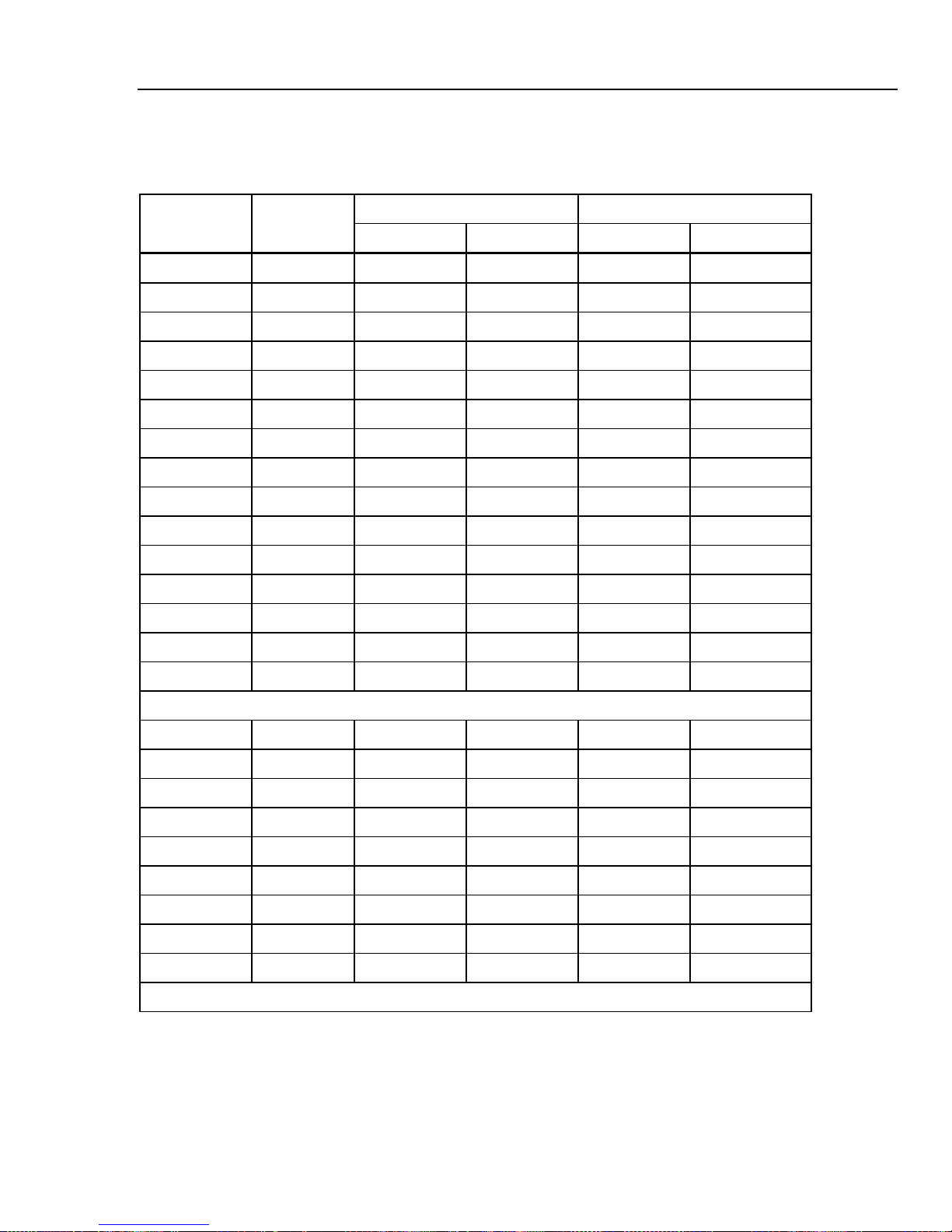
Performance Test and Calibration
Performance Tests 3
Table 3-13. DMM4040/4050 DC Current Veri fication Steps
Nominal
Input
[1]
0 A
100.0 µA 25.0 ηA -25.0 ηA 25.0 ηA -25.0 ηA
100.0 µA
-100.0 µA
0 A
[1]
100.0 µA 100.065 µA 99.935 µA 100.075 µA 99.935 µA
[1]
100.0 µA -99.935 µA -100.065 µA -99.925 µA -100.065 µA
[1]
1.0 mA 50.0 ηA -50.0 ηA 50.0 ηA -50.0 ηA
Range
90-day Test Limits 1-year Test Limits
High Low High Low
1.0 mA 1.0 mA 1.00035 mA 999.65 µA 1.00055 mA 999.45 µA
-1.0 mA 1.0 mA -999.65 µA -1.00035 mA -999.45 µA -1.00055 mA
0 A 10.0 mA 2.0 µA -2.0 µA 2.0 µA -2.0 µA
10.0 mA 10.0 mA 10.005 mA 9.995 mA 10.007 mA 9.993 mA
-10.0 mA 10.0 mA -9.995 mA -10.005 mA -9.993 mA -10.007 mA
0 A 100.0 mA 5.0 µA -5.0 µA 5.0 µA -5.0 µA
100.0 mA 100.0 mA 100.035 mA 99.965 mA 100.055 mA 99.945 m A
-100.0 mA 100. 0 m A -99.965 mA -100.035 mA -99.945 mA -100.055 mA
0 A 400 mA 20.0 µA -20.0 µA 20.0 µA -20.0 µA
400 mA 400 mA 400.18 mA 399.82 mA 400. 22 mA 399.78 mA
-400 mA 400 mA -399.82 mA -400.18 mA -399.78 mA -400.22 mA
Move the connector from the 400 mA jack to the 10 A jack on the UUT for the following st eps.
0 A 1 A 200.0 µA -200.0 µA 200.0 µA -200.0 µA
[1]
1 A
1 A 1.0006 A 999.4 mA 1.0007 A 999.3 mA
[1]
-1 A
1 A -999.4 mA -1.0006 A -999.3 mA -1.0007 A
0 A 3 A 600.0 µA -600.0 µA 600.0 µA -600.0 µA
1.9 A 3 A 1.90212 A 1.89788 A 1.9025 A 1.8975 A
-1.9 A 3 A -1.9978 A -2.0022 A -1.9974 A -2.0026 A
0 A 10 A 800.0 µA -800.0 µA 800.0 µA -800.0 µA
[1]
10 A
10 A 10.0128 A 9.9872 A 10.0158 A 9.9842 A
[1]
-10 A
10 A -9.9872 A -10.0128 A -9.9842 A -10.0158 A
[1] 5520A must be used with 8508A to obtain suitable test uncer t ai nt y r at io.
3-23

DMM4040/4050
Technical Reference Manual
AC Current Verification Steps
Connect the Meter to the test equipment as shown in Figure 3-9 and, depending on which
meter you are calibrating, apply the nominal values listed in Table 3-14. Verification
forms can be found in Appendix A which can be copied and used to record each meter
reading.
The 400 mA range is only available in Outguard version 2.0 and later.
Note
3-24
Figure 3-9. AC Current Equipment Setup
gdc022.eps

Performance Test and Calibration
Table 3-14. DMM4040/4050 AC Current Verification Steps
Performance Tests 3
Nominal Output
90-day Test Limits 1-year Test Limits
Range
Amplitude Freq. High Low High Low
100.0 µA
[1]
10 Hz 100.0 µA 100.14 µA 99.86 µA 100.14 µA 99.86 µA
100.0 µA 1 kHz 100.0 µA 100.14 µA 99.86 µA 100.14 µA 99.86 µA
100.0 µA
100.0 µA
1.0 mA
[1]
5 kHz 100.0 µA 100.14 µA 99.86 µA 100.14 µA 99.86 µA
[1]
10 kHz 100.0 µA 100.45 µA 99.55 µA 100.45 µA 99.55 µA
[1]
10 Hz 1.0 mA 1.0014 mA 998.6 µA 1.0014 mA 998.6 µA
1.0 mA 1 kHz 1.0 mA 1.0014 mA 998.6 µA 1.0014 mA 998.6 µA
[1]
1.0 mA
1.0 mA
10.0 mA
5 kHz 1.0 mA 1.0014 mA 998.6 µA 1.0014 mA 998.6 µA
[1]
10 kHz 1.0 mA 1.0045 mA 995.5 µA 1.0045 mA 995.5 µA
[1]
10 Hz 10.0 mA 10.014 mA 9.986 mA 10.01 4 m A 9.986 mA
10.0 mA 1 kHz 10.0 mA 10.014 mA 9.986 mA 10.014 mA 9.986 mA
10.0 mA
10.0 mA
100.0 mA
[1]
5 kHz 10.0 mA 10.014 mA 9.986 m A 10.01 4 mA 9.986 mA
[1]
10 kHz 10.0 mA 10.045 mA 9.955 mA 10.04 5 mA 9.955 mA
[1]
10 Hz 100.0 mA 100.14 mA 99.86 mA 100.14 mA 99.86 mA
100.0 mA 1 kHz 100.0 mA 100.14 mA 99.86 mA 100.14 mA 99.86 mA
100.0 mA
100.0 mA
329.0 mA
329.0 mA
329.0 mA
329.0 mA
1 A
[1]
5 kHz 100.0 mA 100.14 mA 99.86 m A 100.1 4 mA 99.86 mA
[1]
10 kHz 100.0 mA 100.45 mA 99.55 mA 100.45 mA 99.55 mA
[1]
10 Hz 400 mA 330.387 mA 327.613 mA 330.387 mA 327.613 mA
[1]
1 kHz 400 mA 329.729 mA 328.271 mA 329.729 mA 328.271 mA
[1]
5 kHz 400 mA 332.458 mA 325.542 mA 332.458 mA 325.542 mA
[1]
10 kHz 400 mA 332.458 mA 325.542 mA 332.458 mA 325.542 mA
[1]
45 Hz 1 A 1.0014 A 998.6 mA 1.00140 A 998.6 mA
1 A 1 kHz 1 A 1.0014 A 998.6 mA 1.00140 A 998.6 mA
[1]
1 A
5 kHz 1 A 1.0014 A 998.6 mA 1.00140 A 998.6 mA
[1]
1 A
10 kHz 1 A 1.0105 A 989.5 mA 1.01050 A 989.5 mA
[1]
1.9 A
45 Hz 3 A 1.90465 A 1.89535 A 1.90465 A 1.89535 A
1.9 A 1 kHz 3 A 1.90465 A 1.89630 A 1.90465 A 1.89535 A
[1]
1.9 A
10 kHz 3 A 1.92765 A 1.87235 A 1.92765 A 1.87235 A
[1]
10 A
45 Hz 10 A 10.02100 A 9.97900 A 10.02100 A 9.97900 A
10 A 1 kHz 10 A 10.02100 A 9.97900 A 10.02100 A 9.97900 A
Notes:
[1] Optional test
3-25

DMM4040/4050
Technical Reference Manual
Adjustment (Calibration)
Meter adjustments, or calibration, should be performed at the desired interval, or
whenever a verification test indicates a Meter function is out of tolerance. The Meter
accuracy will stay within specifications only if the adjustment procedure is performed at
regular intervals. A one-year interval is adequate for most applications. The Meter’s
accuracy specifications are not valid beyond the one-year interval.
Meter adjustments are accessed only through the remote interface with a series of
adjustment steps. The remote program directs the test equipment to apply a series of
shorts, opens, voltages, currents, and capacitance (DMM4050 only) to the Meter. At each
step, the Meter internally makes the necessary adjustment to bring the Meter into
specification. No internal mechanical adjustments are necessary.
Using an automated, computer-controlled procedure, the calibration and verification
procedures can be performed on the Meter in under 60 minutes. A sample adjustment
program is listed on the “Sample Adjustment Program” section later in this manual.
The Meter’s adjustments are password protected to prevent accidental or unauthorized
adjustments. The security password must be entered through the front panel or remote
interface before adjustments can be made to the Meter.
Unlocking the Meter for Adjustments (Calibration)
To unlock the Meter for adjustments from the front panel:
1. Press .
2. Press .
3. Press .
Press the soft key labeled
to decrement the character or to increment the
character. The character can be set to 0 through 9, A through Z, period (.), and
dash (-).
To move to the next character, press
.
4. Press to enter the password and unlock the Meter for adjustments.
Find the CALIBRATION:SECURE:STATE command in the “Supported SCPI
Commands” section of the DMM4040 and DMM4050 Programmer Manual for
information on unlocking the Meter for calibration.
The Meter is shipped from the factory with the password set to .
Unlocking the Meter for Adjustments Over a Remote Interface
To unlock the Meter, send the following command:
“CAL:SEC:STAT OFF, TEKDMM40XX”
To relock the Meter, send the following command:
“CAL:SEC:STAT ON, TEKDMM40XX”
Changing the Calibration Password
The calibration password can be changed only through the remote interface. Find the
CALIBRATION:SECURE:CODE command in the “Supported SCPI Commands”
section of the DMM404 and DMM4050 Programmer Manual for information on
changing the calibration password.
3-26

Performance Test and Calibration
Adjustment (Calibration) 3
Resetting the Calibration Password
If the calibration password has is lost or forgotten, the password can be reset to
by performing the following actions.
Note
Before taking the following steps, try to use the factory default password
.
1. Perform the general disassembly steps in the “Disassembly Instructions” section.
2. Connect a jumper across W2, as shown in Figure 3-10.
3. Reconnect the power cord between the Meter and a power outlet.
4. Turn the Meter on.
On power-up, the password will automatically be reset to
.
5. Turn the Meter off and disconnect the power cord.
6. Remove the jumper connected above in step 2.
7. Reassemble the Meter.
3-27
Figure 3-10. Calibration Jumper Location
gdc028.eps

DMM4040/4050
Technical Reference Manual
Changing the Calibration Date
The calibration date is automatically updated when the “CAL:REC” command is sent.
See the DMM4040 and DMM4050 Programmer Manual for more details.
Equipment for Calibration
The required equipment for calibration is that same the equipment listed in Table 3-1.
Adjustment Process
The adjustment steps differ slightly between the DMM4040 and the DMM4050. In both
cases, they are divided into four areas: open adjust, zero adjust, rear panel zero adjust,
and gain adjust.
Table 3-15 lists the step numbers, the description of the adjustment, the measurement
adjustment type (open, zero, or gain adjust), the Meter value/range being adjusted, the
amplitude of the adjustment signal, and if required the frequency of the adjustment
signal.
Table 3-15. DMM4040/4050 Adjustment Steps
Step Modes Value Range Input Signal Description Series
Open
0 ORES 100000000 open
1 ORES 1000000000 open
2 ZCAP 1.00E-09 open
ACV
Zero
3 ZVAC 100.0E-3 4-wire low-thermal short AC 100 m V Y
4 ZVACS 100.0E-3 4-wire low-thermal short AC 100 mV Y
5 ZVAC 1 4-wire low-thermal short AC 1V Y
6 ZVACS 1 4-wire low-thermal short AC 1V Y
7 ZVAC 10 4-wire low-thermal short AC 10V Y
8 ZVACS 10 4-wire low-thermal short AC 10V Y
OHM 100M open
terminals
OHM 1G open terminals
(DMM4050 only)
CAP 1 nF open
terminals (DMM4050
only)
Y
Y
N
9 ZVAC 100 4-wire low-thermal short AC 100V Y
10 ZVACS 100 4-wire low-thermal short AC 100V Y
11 ZVAC 1000 4-wire l ow -thermal short AC 1000V Y
12 ZVACS 1000 4-wire low-thermal short
3-28
AC 1000V
N

Performance Test and Calibration
Step Modes Value Range Input Signal Description Series
Adjustment (Calibration) 3
DCV
Zero
13 ZVDC 1000 4-wire low-thermal short DC 1000V Y
14 ZVDC 100 4-wire low-thermal short DC 100V Y
15 ZVDC 10 4-wire low-thermal short DC 10V Y
16 ZVDC 1 4-wire low-thermal short DC 1V Y
17 ZVDC 0.1 4-wir e low-thermal short DC 100mV N
18 DFVDC 0.1 4-wire low-thermal short DC 100mV N
Ohm
Zero
19 ZRES 10000000 4-wire low-thermal short 4W Ohm 10 MOHM Y
20 ZRES 1000000 4-wire low-thermal shor t 4W 1 MOHM Y
21 ZRES 100000 4-wire low-thermal short 4W 100 kOHM Y
22 ZRES 10000 4-wire low-thermal short 4W 10 kOHM Y
23 ZRES 1000 4-wir e low-thermal short 4W 1 kOHM Y
24 ZRES 100 4-wire low-thermal short 4W 100 OHM Y
Table3-15. DMM4040/4050 Adjustment Steps (cont)
Step Modes Value Range Input Signal Description Series
25 ZRES 10 4-wire low-thermal short
Rear Ω
Zero
26 ZRES 100000 4-wire low-thermal short 4W 100 kOHM rear input
27 ZRES 10000 4-wire low-thermal short 4W 10 kOHM rear input
28 ZRES 1000 4-wir e low-thermal short 4W 1 kOHM rear input Y
29 ZRES 100 4-wire low-thermal short 4W 100 OHM rear input
30
Rear
DCV
Zero
31 ZVDC 1 4-wire low-thermal short DC 1V rear i nput Y
32 ZVDC 0.1 4-wir e low-thermal short DC 100 mV re ar i nput N
Low I
Zero
ZRES 10 4-wire low-thermal short
4W 10 OHM (DMM4050
only)
4W 10 OHM rear input
(DMM4050 only)
N
Y
Y
Y
N
33 ZIDC 100.0E-3 100mA to Lo short DC 100 mA Y
3-29

DMM4040/4050
Technical Reference Manual
34 ZIDC 1.0E-3 100mA to Lo short DC 1 mA Y
35 ZIDC 10.0E-3 100mA to Lo short DC 10 mA Y
36 ZIDC 100.0E-6 100mA to Lo short DC 100 uA Y
37 ZIAC 0.0 100mA to Lo short AC 100 uA Y
38 ZIACS 0.0 100mA to Lo short AC 100 uA Y
39 ZIAC 1.0E-3 100mA to Lo short AC 1 mA Y
40 ZIACS 1.0E-3 100mA to Lo short AC 1 mA Y
41 ZIAC 10.0E-3 100mA to Lo short AC 10 A Y
42 ZIACS 10.0E-3 100mA to Lo short AC 10 mA Y
43 ZIAC 100.0E-3 100mA to Lo short AC 100 mA Y
44 ZIACS 100.0E-3 100mA to Lo short AC 100 mA N
Hi I Zero
45 ZIDC 10 10 A to Lo short DC 10 A Y
46 ZIDC 1 10 A to Lo short DC 1 A Y
47 ZIAC 1 10 A to Lo short AC 1 A Y
Table3-15. DMM4040/4050 Adjustment Steps (cont)
Step Modes Value Range Input Signal Description Series
48 ZIACS 1 10 A to Lo short AC 1 A Y
49 ZIAC 10 10 A to Lo short AC 10 A Y
AC ZIACS 10 10 A to Lo short AC 10 A N
50 Linearity
51 ACLIN 1.19 1.19 @1200 Hz AC 1 V N
52 ACLIN 0.8 0.8 @1200 Hz AC 1 V N
53 ACLIN 0.4 0.4 @1200 Hz AC 1 V N
54 ACLIN 0.005 0.005 @1200 Hz AC 1 V N
ACV
Gain
55 GVAC 0.1 0.1 @1200 Hz AC 100 mV Y
56 GVACS 0.1 0.1 @1200 Hz AC 100 mV N
57 ACPOLE 0.1 0.1 @50000 Hz A 100 mV N
58 GVAC 1 1 @1200 Hz AC 1 V Y
59 GVACS 1 1 @1000 Hz AC 1 V N
60 FVAC 1 1 @10 Hz AC 1 V N
61 ACPOLE 1 1 @50000 Hz AC 1 V N
3-30

Performance Test and Calibration
62 GVAC 10 10 @1200 Hz AC 10 V Y
63 GVACS 10 10 @1200 Hz AC 10 V N
64 ACPOLE 10 10 @50000 Hz AC 10 V N
65 GVAC 100 100 @1200 Hz AC 100 V Y
66 GVACS 100 100 @1200 Hz AC 100 V N
67 ACPOLE 100 100 @50000 H z AC 100 V N
AC 1000 V (DMM4040
68 GVAC 1000 1000 @1200 Hz
69 GVACS 1000 1000 @1200 Hz
uses 750V on 750V
range)
AC 1000 V (DMM4040
uses 750V on 750V
range)
Adjustment (Calibration) 3
Y
N
70 ACPOLE 1000 329 @50000 Hz
VDC
Gain
71 GVDC 1000 1000 DC 1000 V N
72 GVDC -1000 -1000 DC 1000 V N
73 GVDC 100 100 DC 100 V N
74 GVDC -100 -100 DC 100 V N
Table 3-15. DMM4040/4050 Adjustment Steps (cont)
Step Modes Value Range Input Signal Description Series
75 GVDC 10 10 DC 10 V N
76 GVDC -10 -10 DC 10 V N
77 GVDC 1 1 DC 1 V N
78 GVDC -1 -1 DC 1 V N
79 GVDC 0.1 0.1 DC 100 mV N
80 GVDC -0.1 -0.1 DC 100 mV N
AC 1000 V (DMM4040
uses 750V range)
N
Hi IDC
Gain
81 GIDC 1 1 DC 1 A N
82 GIDC -1 -1 DC 1 A N
83 GIDC 10 10 DC 10 A N
84 GIDC -10 -10 DC 10 A N
Hi IAC
Gain
85 GIAC 10 10 AC 10 A Y
3-31

DMM4040/4050
Technical Reference Manual
86 GIACS 10 10 AC 10 A N
87 GIAC 1 1 AC 1 A Y
88 GIACS 1 1 AC 1 A N
Low IAC
Gain
89 GIAC 100.0E-3 100.0E-3 AC 100 mA Y
90 GIACS 100.0E-3 100.0E-3 AC 100 mA N
91 GIAC 10.0E-3 10.0E-3 AC 10 mA Y
92 GIACS 10.0E-3 10.0E-3 AC 10 mA N
93 GIAC 1.0E-3 1.0E-3 AC 1 mA Y
94 GIACS 1.0E-3 1.0E-3 AC 1 mA N
95 GIAC 100.0E-6 100.0E-6 AC 100 uA N
96 GIACS 100.0E-6 100.0E-6 AC 100 uA N
Lo IDC
Gain
97 GIDC 100.0E-6 100.0E-6 DC 100 uA N
98 GIDC -100.0E-6 -100.0E-6 DC 100 uA N
99 GIDC 1.0E-3 1.0E-3 DC 1 mA N
100 GIDC -1.0E-3 -1.0E-3 DC 1 mA N
3-32

Performance Test and Calibration
Table 3-16. DMM4040/4050 Adjustment Steps (cont)
Step Modes Value Range Input Signal Description Series
101 GIDC 10.0E-3 10.0E-3 DC 10 mA N
102 GIDC -10.0E-3 -10.0E-3 DC 10 mA N
103 GIDC 100.0E-3 100.0E-3 DC 100 mA N
104 GIDC -100.0E-3 -100.0E-3 DC 100 mA N
Ω Gain
105 GRES 100000000 100000000 R 100M Ω N
106 GRES 10000000 10000000 4W 10M Ω N
107 GRES 1000000 1000000 4W 1M Ω N
108 GRES 100000 100000 4W 100 kΩ N
109 GRES 10000 10000 4W 10 kΩ N
110 GRES 1000 1000 4W 1 kΩ N
Adjustment (Calibration) 3
111 GRES 100 100 4W 100 Ω N
4W 10 Ω (DMM4050
112 GRES 10 10
Misc
Gain
113 GRES 1000000000 1000000000 R1G Ω (DMM4050 only)
114 GCAP1 10.0E-9 10.0E-9 C10NF (DMM4050 only)
115 GCAP2 10.0E-9 10.0E-9 C10NF (DMM4050 only)
only)
N
N
Y
N
Once familiar with the calibration series of setups, the calibration time may be sped up by
using the command “CAL OFF”. This command allows the instrument to automatically
go to the next logical step in the series. The last column in Table 3-15 identifies which
steps in the series can be run automatically. For example, all of the Open steps can be run
by entering:
CAL:CAL ORES, 100000000
CAL? OFF
Another example is automatically running the ACV zeros from step 3 through step 12 in
Table 3-15 with:
CAL:CAL ZVAC, 100.0E-3
CAL? OFF
Using the CAL? command without an argument turns off the single step
feature.
AC linearity steps must be run with AC Gain steps t o complete the AC
calibration.
3-33
Notes

DMM4040/4050
Technical Reference Manual
Aborting a Calibration Process
Aborting a calibration process while the Meter is attempting to
write new calibration constants to memory may corrupt the
calibration constants memory.
To abort a running calibration process, stop the program or issue a device clear command
over the remote interface. No constants are saved until the Meter receives a record
command.
Sample Adjustment Program
The example below shows an IEEE 488 program that uses some of the commands to
adjust the 1V ACV portion of the Meter. Note that the ACV linearity adjustment must be
followed with a gain adjustment. Print is an output command to the Meter. Input Line
reads a response from the Meter.
INIT PORT 0<CR>
CLEAR PORT 0<CR>
# Enable Calibration
PRINT @<address of meter>, "CAL:SEC:STAT OFF, TEKDMM40XX"
# Zeros
### Calibrate AC Linearity Set input value to 1.19V@1200Hz
# V@1200Hz
PRINT @<address of meter>, "CAL:VAL ACLIN,1.19"
PRINT @<address of meter>, "CAL? ON"
INPUT LINE @<address of meter>, A$
### Calibrate AC Linearity Set input value to 0.8V@1200Hz
# 0.8V@1200Hz
PRINT @<address of meter>, "CAL:VAL ACLIN,0.8"
PRINT @<address of meter>, "CAL? ON"
INPUT LINE @<address of meter>, A$
### Calibrate AC Linearity Set input value to 0.4V@1200Hz
# 0.4V@1200Hz
PRINT @<address of meter>, "CAL:VAL ACLIN,0.4"
PRINT @<address of meter>, "CAL? ON"
INPUT LINE @<address of meter>, A$
### Calibrate AC Linearity Set input value to 0.05V@1200Hz
# 0.005V@1200Hz
PRINT @<address of meter>, "CAL:VAL ACLIN,0.005"
PRINT @<address of meter>, "CAL? ON"
INPUT LINE @<address of meter>, A$PRINT @<address of meter>, "CAL:VAL"
### ACV Gain for 1V
PRINT @<address of meter>, "CAL:VAL ZVAC,1"
PRINT @<address of meter>, "CAL? ON"
INPUT LINE @<address of meter>, A$
PRINT @<address of meter>, "CAL:VAL ZVACS,1"
PRINT @<address of meter>, "CAL? ON"
INPUT LINE @<address of meter>, A$
# Disable Calibration
PRINT @<address of meter>, "CAL:SEC:STAT ON, TEKDMM40XX”
Caution
For more information about writing a program to remotely control the Meter, refer to the
DMM4040 and DMM4050 Programmer Manual.
3-34

Appendices
Appendix Title Page
A Verification Forms .............................................................................................. A-1
B Example Adjustment Program ............................................................................ B-1

DMM4040/4050
Technical Referencel

Introduction
The following tables are forms used to collect Meter readings while performing the
verification procedures contained in Chapter 3. Appendix pages may be copied as needed
to record meter readings.
Appendix A
Verification Forms
A-1

DMM4040/4050
Technical Referencel
Table A-1. Blank Verification Record for 90-Day Specifications
Nominal Output
Range
Ampl. Freq. High Low
DMM4050 DC Volts
0 0.100 3.5E-6 -3.5E-6
100.0E-3 0.100 100.006E-3 99.994E-3
-100.0E-3 0.100 -99.994E-3 -100.006E-3
0 1 7.0E-6 -7.0E-6
1 1 1.000025 0.999975
-1 1 -0.999975 -1.000025
0 10 50.0E-6 -50.0E-6
5 10 5.000140 4.999860
-5 10 -4.999860 -5.000140
10 10 10.000230 9.999770
-10 10 -9.999770 -10.000230
0 100 600.0E-6 -600.0E-6
100 100 100.0033 99.9967
Test Limits
Results Pass/Fail
-100 100 -99.9967 -100.0033
0 1000 10.0E-3 -10.0E-3
1000 1000 1000.0410 999.9590
-1000 1000 -999.9590 -1000.0410
DMM4050 DC Ratio
100.0E-3 0.100 1.00012 0.99988
1 1 1.00005 0.99995
-10 10 1.000046 0.999954
DMM4040 DC Volts
0 0.100 3.5E-6 -3.5E-6
100.0E-3 0.100 100.0075E-3 99.9925E-3
-100.0E-3 0.100 -99.9925E-3 -100.0075E-3
0 1 7.0E-6 -7.0E-6
1 1 1.000037E+0 999.963E-3
-1 1 -999.963E-3 -1.000037E+0
0 10 50.0E-6 -50.0E-6
5 10 5.00015E+0 4.99985E+0
-5 10 -4.99985E+0 -5.00015E+0
A-2

Appendices
Table A-1. Blank Verification Record for 90-Day Specifications (cont)
Verification Forms A
Nominal Output
Range
Ampl. Freq. High Low
DMM4040 DC Volts (cont)
10 10 10.00025E+0 9.99975E+0
-10 10 -9.99975E+0 -10.00025E+0
0 100 600.0E-6 -600.0E-6
100 100 100.0041E+0 99.9959E+0
-100 100 -99.9959E+0 -100.0041E+0
0 1000 10.0E-3 -10.0E-3
1000 1000 1.000045E+3 999.955E+0
-1000 1000 -999.955E+0 -1.000045E+3
DMM4040 DC Ratio
100.0E-3 0.100 1.00015 0.99985
1 1 1.000074 0.999926
-10 10 1.00005 0.99995
DMM4040/4050 AC Volts
Test Limits
Results Pass/Fail
100.0E-3 10 0.100 100.09E-3 99.91E-3
100.0E-3 20000 0.100 100.09E-3 99.91E-3
100.0E-3 50000 0.100 100.16E-3 99.84E-3
100.0E-3 100000 0.100 100.68E-3 99.32E-3
100.0E-3 300000 0.100 104.5E-3 95.5E-3
1 10 1 1.0008E+0 999.2E-3
1 20000 1 1.0008E+0 999.2E-3
1 50000 1 1.0016E+0 998.4E-3
1 100000 1 1.0068E+0 993.2E-3
1 300000 1 1.045E+0 955.0E-3
10 10 10 10.008E+0 9.992E+0
10 20000 10 10.008E+0 9.992E+0
10 50000 10 10.016E+0 9.984E+0
10 100000 10 10.068E+0 9.932E+0
3 300000 10 3.17E+0 2.83E+0
A-3

DMM4040/4050
Technical Referencel
Table A-1. Blank Verification Record for 90-Day Specifications (cont)
Nominal Output
Range
Ampl. Freq. High Low
DMM4040/4050 AC Volts (cont)
100 45 100 100.08E+0 99.92E+0
100 20000 100 100.08E+0 99.92E+0
100 50000 100 100.16E+0 99.84E+0
100 100000 100 100.68E+0 99.32E+0
DMM4040/4050 Only AC Volts
1000 45 1000 1000.800 999.200
1000 1000 1000 1000.800 999.200
1000 10000 1000 1000.800 999.200
320 20000 1000 320.460 319.540
320 50000 1000 320.852E+0 319.148E+0
320 100000 1000 322.72E+0 317.28E+0
DMM4040/4050 Frequency
1 10 10.00300 9.99700
Test Limits
Results Pass/Fail
1 40 40.00400 39.99600
0.1 300000 300030.0 299970.0
0.1 1000000 1000100.0 999900.0
DMM4040/4050 Only 4-Wire Resistance
0 10 3.0E-3 0
10 10 10.00380 9.99620
0 100 4.0E-3 0
100 100 100.0120 99.9880
0 1000 10.0E-3 0
A-4

Appendices
00000
1000000000
Table A-1. Blank Verification Record for 90-Day Specifications (cont)
Verification Forms A
Nominal Output
Range
Ampl. Freq. High Low
DMM4040/4050 4-Wire Resistance (cont)
1000 1000 1000.090 999.910
0 10000 100.0E-3 0
10000 10000 10000.90 9999.10
0 100000 1.000000 0
100000 100000 100009.0 99991.0
0 100 0.0040 0
100 100 100.0120 99.9880
0 1000 10.0E-3 0
1000 1000 1000.090 999.910
0 10000 100.0E-3 0
10000 10000 10000.90 9999.10
0 100000 1.000000 0
100000 100000 100009.0 99991.0
Test Limits
Results Pass/Fail
0 1000000 10.00000 0
1000000 1000000 1000090 999910
0 10000000 100.0000 0
10000000 10000000 10002100 9997900
0 100000000 10000.00 0
100000000 100000000 100810000 99190000
0 10000
1000000000
DMM4040/4050 Optional 2X4 Test Lead (Split Lead) test
0 100 4.0E-3 0
100 100 100.0120 99.9880
DMM4050 Optional Rear Panel Test
10 V DCV (10V) 10.00023 V 9.99977 V
1000 Ω 4-W Ω (1 kΩ) 1000.09 Ω 999.91 Ω
100 mA DCI (100 mA) 0.100035 A 0.099965 A
100000.0 0
1015100000 984900000
A-5

DMM4040/4050
Technical Referencel
Table A-1. Blank Verification Record for 90-Day Specifications (cont)
Nominal Output
Range
Ampl. Freq. High Low
DMM4040 Optional Rear Panel Test
10 V DCV (10V) 10.00025 V 9.99975 V
1000 Ω 4-W Ω (1 kΩ) 1000.09 Ω 999.91 Ω
100 mA DCI (100 mA) 0.100035 A 0.099965 A
DMM4050 Capacitance
0 1.0E-9 25.0E-12 0
1.0E-9 1.0E-9 1.045E-9 955.0E-12
10.0E-9 10.0E-9 10.15E-9 9.85E-9
100.0E-9 100.0E-9 101.5E-9 98.5E-9
1.0E-6 1.0E-6 1.015E-6 985.0E-9
10.0E-6 10.0E-6 10.15E-6 9.85E-6
100.0E-6 100.0E-6 101.5E-6 98.5E-6
1.0E-3 1.0E-3 1.015E-3 985.0E-6
10.0E-3 10.0E-3 10.15E-3 9.85E-3
Test Limits
Results Pass/Fail
100.0E-3 100.0E-3 104.2E-3 95.8E-3
DMM4040/4050 DC Current
0 100.0E-6 25.0E-9 -25.0E-9
100.0E-6 100.0E-6 100.065E-6 99.935E-6
-100.0E-6 100.0E-6 -99.935E-6 -100.065E-6
0 1.0E-3 50.0E-9 -50.0E-9
1.0E-3 1.0E-3 1.00035E-3 999.65E-6
-1.0E-3 1.0E-3 -999.65E-6 -1.00035E-3
0 10.0E-3 2.0E-6 -2.0E-6
10.0E-3 10.0E-3 10.005E-3 9.995E-3
-10.0E-3 10.0E-3 -9.995E-3 -10.005E-3
0 100.0E-3 5.0E-6 -5.0E-6
100.0E-3 100.0E-3 100.035E-3 99.965E-3
-100.0E-3 100.0E-3 -99.965E-3 -100.035E-3
0 400.0E-3 20.0E-6 20.0E-6
400.0E-3 400.0E-3 400.18E-3 399.82E-3
-400.0E-3 400.0E-3 399.82E-3 400.18E-3
0 1 200.0E-6 -200.0E-6
A-6

Appendices
Table A-1. Blank Verification Record for 90-Day Specifications (cont)
Verification Forms A
Nominal Output
Range
Ampl. Freq. High Low
DMM4040/4050 DC Current (cont)
1 1 1.0006E+0 999.4E-3
-1 1 -999.4E-3 -1.0006E+0
0 3 600.0E-6 -600.0E-6
1.9 3 1.90212E+0 1.89788E+0
-1.9 3 -1.89788E+0 -1.90212E+0
0 10 800.0E-6 -800.0E-6
10 10 10.0128E+0 9.9872E+0
-10 10 -9.9872E+0 -10.0128E+0
DMM4050 Only AC Current
100.0E-6 100.0E-6 100.0E-6 100.0E-6 100.0E-6 100.0E-6 100.0E-6
100.0E-6 100.0E-6 100.0E-6 100.0E-6 100.0E-6 100.0E-6 100.0E-6
100.0E-6 100.0E-6 100.0E-6 100.0E-6 100.0E-6 100.0E-6 100.0E-6
100.0E-6 100.0E-6 100.0E-6 100.0E-6 100.0E-6 100.0E-6 100.0E-6
Test Limits
Results Pass/Fail
1.0E-3 1.0E-3 1.0E-3 1.0E-3 1.0E-3 1.0E-3 1.0E-3
1.0E-3 1.0E-3 1.0E-3 1.0E-3 1.0E-3 1.0E-3 1.0E-3
1.0E-3 1.0E-3 1.0E-3 1.0E-3 1.0E-3 1.0E-3 1.0E-3
1.0E-3 1.0E-3 1.0E-3 1.0E-3 1.0E-3 1.0E-3 1.0E-3
DMM4040/4050 Current
10.0E-3 10.0E-3 10.0E-3 10.0E-3 10.0E-3 10.0E-3 10.0E-3
10.0E-3 10.0E-3 10.0E-3 10.0E-3 10.0E-3 10.0E-3 10.0E-3
10.0E-3 10.0E-3 10.0E-3 10.0E-3 10.0E-3 10.0E-3 10.0E-3
10.0E-3 10.0E-3 10.0E-3 10.0E-3 10.0E-3 10.0E-3 10.0E-3
100.0E-3 100.0E-3 100.0E-3 100.0E-3 100.0E-3 100.0E-3 100.0E-3
100.0E-3 1000 100.0E-3 100.14E-3 99.86E-3
100.0E-3 5000 100.0E-3 100.14E-3 99.86E-3
100.0E-3 10000 100.0E-3 100.45E-3 99.55E-3
329.0E-3 10 400.0E-3 330.387E-3 327.613E-3
329.0E-3 1000 400.0E-3 329.729E-3 328.271E-3
329.0E-3 5000 400.0E-3 332.458E-3 325.542E-3
329.0E-3 10000 400.0E-3 332.458E-3 325.542E-3
1 45 1 1.0014E+0 998.6E-3
A-7

DMM4040/4050
Technical Referencel
Table A-1. Blank Verification Record for 90-Day Specifications (cont)
Nominal Output
Range
Ampl. Freq. High Low
DMM4040/4050 Current (cont)
10 45 10 10.02100 9.97900
10 1000 10 10.02100 9.97900
1 1000 1 1.0014E+0 998.6E-3
1 5000 1 1.0014E+0 998.6E-3
1 10000 1 1.0105E+0 989.5E-3
1.9 45 3 1.90465 1.89535
1.9 1000 3 1.90465 1.89630
1.9 10000 3 1.92765 1.87235
Test Limits
Results Pass/Fail
A-8

Appendices
Table A-2. Blank Verification Record for 1-Year Specifications
Verification Forms A
Nominal Output
Range
Ampl. Freq. High Low
DMM4050 DC Volts
0 0.100 3.5E-6 -3.5E-6
100.0E-3 0.100 100.0072E-3 99.9928E-3
-100.0E-3 0.100 -99.9928E-3 -100.0072E-3
0 1 7.0E-6 -7.0E-6
1 1 1.000032 0.999968
-1 1 -0.999968 -1.000032
0 10 50.0E-6 -50.0E-6
5 10 5.000170 4.999830
-5 10 -4.999830 -5.000170
10 10 10.000290 9.999710
-10 10 -9.999710 -10.000290
0 100 600.0E-6 -600.0E-6
100 100 100.0044 99.9956
Test Limits
Results Pass/Fail
-100 100 -99.9956 -100.0044
0 1000 10.0E-3 -10.0E-3
1000 1000 1000.0510 999.9490
-1000 1000 -999.9490 -1000.0510
DMM4050 DC Ratio
100.0E-3 0.100 1.000144E+0 0.999856E+0
1 1 1.000064E+0 0.999936E+0
-10 10 1.000058E+0 0.999942E+0
DMM4040 DC Volts
0 0.100 3.5E-6 -3.5E-6
100.0E-3 0.100 100.0085E-3 99.9915E-3
-100.0E-3 0.100 -99.9915E-3 -100.0085E-3
0 1 7.0E-6 -7.0E-6
1 1 1.000047E+0 999.953E-3
-1 1 -999.953E-3 -1.000047E+0
0 10 50.0E-6 -50.0E-6
5 10 5.000225E+0 4.999775E+0
-5 10 -4.999775E+0 -5.000225E+0
A-9

DMM4040/4050
Technical Referencel
Table A-2. Blank Verification Record for 1-Year Specifications (cont)
Nominal Output
Range
Ampl. Freq. High Low
DMM4040 DC Volts (cont)
10 10 10.0004E+0 9.9996E+0
-10 10 -9.9996E+0 -10.0004E+0
0 100 600.0E-6 -600.0E-6
100 100 100.0051E+0 99.9949E+0
-100 100 -99.9949E+0 -100.0051E+0
0 1000 10.0E-3 -10.0E-3
1000 1000 1.000055E+3 999.945E+0
-1000 1000 -999.945E+0 -1.000055E+3
DMM4040 DC Ratio
100.0E-3 0.100 1.00017E+0 0.99983E+0
1 1 1.000094E+0 0.999906E+0
-10 10 1.000080E+0 0.99992E+0
DMM4040/4050 AC Volts
Test Limits
Results Pass/Fail
100.0E-3 10 0.100 100.1E-3 99.9E-3
100.0E-3 20000 0.100 100.1E-3 99.9E-3
100.0E-3 50000 0.100 100.17E-3 99.83E-3
100.0E-3 100000 0.100 100.68E-3 99.32E-3
100.0E-3 300000 0.100 104.5E-3 95.5E-3
1 10 1 1.0009E+0 999.1E-3
1 20000 1 1.0009E+0 999.1E-3
1 50000 1 1.0017E+0 998.3E-3
1 100000 1 1.0068E+0 993.2E-3
1 300000 1 1.045E+0 955.0E-3
10 10 10 10.009E+0 9.991E+0
10 20000 10 10.009E+0 9.991E+0
10 50000 10 10.017E+0 9.983E+0
10 100000 10 10.068E+0 9.932E+0
3 300000 10 3.17E+0 2.83E+0
A-10

Appendices
Table A-2. Blank Verification Record for 1-Year Specifications (cont)
Verification Forms A
Nominal Output
Range
Ampl. Freq. High Low
DMM4040/4050 AC Volts (cont)
100 45 100 100.09E+0 99.91E+0
100 20000 100 100.09E+0 99.91E+0
100 50000 100 100.17E+0 99.83E+0
100 100000 100 100.68E+0 99.32E+0
DMM4040/4050 Only AC Volts
1000 45 1000 1.0009E+3 999.1E+0
1000 1000 1000 1.0009E+3 999.1E+0
1000 10000 1000 1.0009E+3 999.1E+0
320 20000 1000 320.492E+0 319.508E+0
320 50000 1000 320.884E+0 319.116E+0
320 100000 1000 322.72E+0 317.28E+0
DMM4040/4050 Frequency
1 10 10.00300 9.99700
Test Limits
Results Pass/Fail
1 40 40.00400 39.99600
0.1 300000 300030.0 299970.0
0.1 1000000 1000100.0 999900.0
DMM4040/4050 Only 4-Wire Resistance
0 10 3.0E-3 0
10 10 10.00400 9.99600
0 100 4.0E-3 0
100 100 100.01400 99.98600
0 1000 10.0E-3 0
A-11

DMM4040/4050
1000000000
1000000000
Technical Referencel
Table A-2. Blank Verification Record for 1-Year Specifications (cont)
Nominal Output
Range
Ampl. Freq. High Low
DMM4040/4050 4-Wire Resistance (cont)
1000 1000 1000.11000 999.89000
0 10000 100.0E-3 0
10000 10000 10001.10 9998.90
0 100000 1.000000 0
100000 100000 100011.0 99989.0
DMM4040/4050 2-Wire Resistance
0 100 0.0040 0
100 100 100.0140 99.99
0 1000 10.0E-3 0
1000 1000 1000.11000 999.89000
0 10000 100.0E-3 0
10000 10000 10001.10 9998.90
0 100000 1.000000 0
Test Limits
Results Pass/Fail
100000 100000 100011.0 99989.0
0 1000000 10.00000 0
1000000 1000000 1000110 999890
0 10000000 100.0000 0
10000000 10000000 10004100 9995900
0 100000000 10000.00 0
100000000 100000000 100810000 99190000
0
1000000000
DMM4040/4050 Optional 2X4 Test Lead (Split Lead) test
0 100 4.0E-3 0
100 100 100.01400 99.98600
DMM4050 Optional Rear Panel Test
10 V DCV (10V) 10.00029 V 9.99971 V
1000 Ω 4-W Ω (1 kΩ) 1000.11 Ω 999.89 Ω
100 mA DCI (100 mA) 0.100055 A 0.099945 A
100000.0 0
1020100000 979900000
A-12
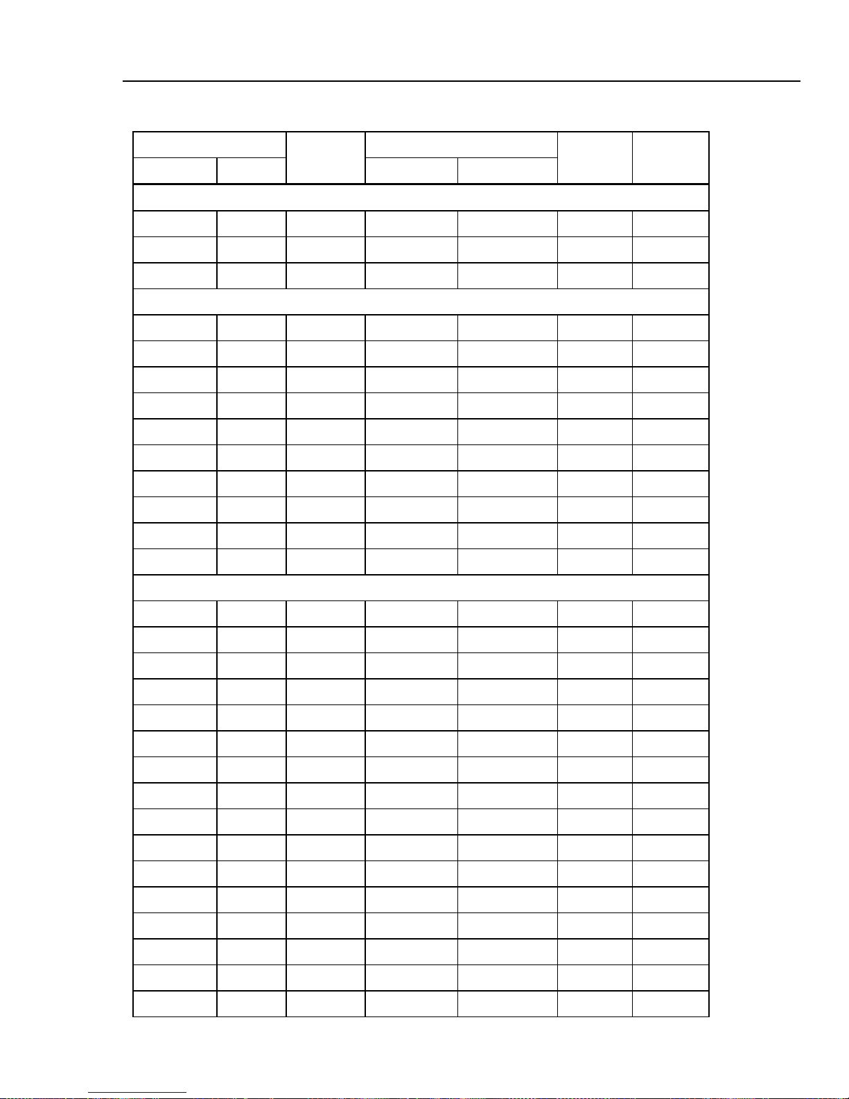
Appendices
Table A-2. Blank Verification Record for 1-Year Specifications (cont)
Verification Forms A
Nominal Output
Range
Ampl. Freq. High Low
DMM4040 Optional Rear Panel Test
100 mV DCV (10V) 0.1000085 V 0.0999915 V
1000 Ω 4-W Ω (1 kΩ) 1000.11 Ω 999.89 Ω
100 mA DCI (100 mA) 0.100055 A 0.099945 A
DMM4050 Capacitance
0 1.0E-9 25.0E-12 0
1.0E-9 1.0E-9 1.045E-9 955.0E-12
10.0E-9 10.0E-9 10.15E-9 9.85E-9
100.0E-9 100.0E-9 101.5E-9 98.5E-9
1.0E-6 1.0E-6 1.015E-6 985.0E-9
10.0E-6 10.0E-6 10.15E-6 9.85E-6
100.0E-6 100.0E-6 101.5E-6 98.5E-6
1.0E-3 1.0E-3 1.015E-3 985.0E-6
10.0E-3 10.0E-3 10.15E-3 9.85E-3
Test Limits
Results Pass/Fail
100.0E-3 100.0E-3 104.2E-3 95.8E-3
DMM4040/4050 DC Current
0 100.0E-6 25.0E-9 -25.0E-9
100.0E-6 100.0E-6 100.075E-6 99.935E-6
-100.0E-6 100.0E-6 -99.925E-6 -100.065E-6
0 1.0E-3 50.0E-9 -50.0E-9
1.0E-3 1.0E-3 1.00055E-3 999.45E-6
-1.0E-3 1.0E-3 -999.45E-6 -1.00055E-3
0 10.0E-3 2.0E-6 -2.0E-6
10.0E-3 10.0E-3 10.007E-3 9.993E-3
-10.0E-3 10.0E-3 -9.993E-3 -10.007E-3
0 100.0E-3 5.0E-6 -5.0E-6
100.0E-3 100.0E-3 100.055E-3 99.945E-3
-100.0E-3 100.0E-3 -99.945E-3 -100.055E-3
0 400.0E-3 20.0E-6 20.0E-6
400.0E-3 400.0E-3 400.22E-3 399.78E-3
-400.0E-3 400.0E-3 399.78E-3 400.22E-3
0 1 200.0E-6 -200.0E-6
A-13

DMM4040/4050
Technical Referencel
Table A-2. Blank Verification Record for 1-Year Specifications (cont)
Nominal Output
Range
Ampl. Freq. High Low
DMM4040/4050 DC Current (cont)
1 1 1 1 1 1 1
-1 -1 -1 -1 -1 -1 -1
0 0 0 0 0 0 0
1.9 1.9 1.9 1.9 1.9 1.9 1.9
-1.9 -1.9 -1.9 -1.9 -1.9 -1.9 -1.9
0 0 0 0 0 0 0
10 10 10 10 10 10 10
-10 -10 -10 -10 -10 -10 -10
DMM4040/4050 Only AC Current
100.0E-6 10 100.0E-6 100.14E-6 99.86E-6
100.0E-6 1000 100.0E-6 100.14E-6 99.86E-6
100.0E-6 5000 100.0E-6 100.14E-6 99.86E-6
100.0E-6 10000 100.0E-6 100.45E-6 99.55E-6
Test Limits
Results Pass/Fail
1.0E-3 10 1.0E-3 1.0014E-3 998.6E-6
1.0E-3 1000 1.0E-3 1.0014E-3 998.6E-6
1.0E-3 5000 1.0E-3 1.0014E-3 998.6E-6
1.0E-3 10000 1.0E-3 1.0045E-3 995.5E-6
10.0E-3 10 10.0E-3 10.014E-3 9.986E-3
10.0E-3 1000 10.0E-3 10.014E-3 9.986E-3
10.0E-3 5000 10.0E-3 10.014E-3 9.986E-3
10.0E-3 10000 10.0E-3 10.045E-3 9.955E-3
100.0E-3 10 100.0E-3 100.14E-3 99.86E-3
100.0E-3 1000 100.0E-3 100.14E-3 99.86E-3
100.0E-3 5000 100.0E-3 100.14E-3 99.86E-3
100.0E-3 10000 100.0E-3 100.45E-3 99.55E-3
329.0E-3 10 400.0E-3 330.387E-3 327.613E-3
329.0E-3 1000 400.0E-3 329.729 E-3 328.271E-3
329.0E-3 5000 400.0E-3 332.458E-3 325.542E-3
329.0E-3 10000 400.0E-3 332.458E-3 325.542E-3
1 45 1 1.00140 998.6E-3
1 1000 1 1.00140 998.6E-3
A-14

Appendices
Table A-2. Blank Verification Record for 1-Year Specifications (cont)
Verification Forms A
Nominal Output
Range
Ampl. Freq. High Low
DMM4040/4050 AC Current (cont)
10 45 10 10.02100 9.97900
10 1000 10 10.02100 9.97900
1 5000 1 1.00140 998.6E-3
1 10000 1 1.01050 989.5E-3
1.9 45 3 1.90465 1.89535E+0
1.9 1000 3 1.90465 1.89535E+0
1.9 10000 3 1.92765 1.87235E+0
Test Limits
Results Pass/Fail
A-15

DMM4040/4050
Technical Referencel
A-16

Appendix B
Example Adjustment Program
Introduction
Shown below is an adjustment program example for the DMM4040 and DMM4050.
###DMM4040/4050 Calibration Adjustment Meta Program
*RST;SYST:REM
CAL:SEC:STAT OFF, TEKDMM40XX
# Open Adjust
## Remove all connections to front terminals
CAL:VAL ORES,100000000
CAL? ON
#
# DMM4050 Only - comment out if calibrating a DMM4040
#
CAL:VAL ORES,1000000000
CAL? ON
CAL:VAL ZCAP,1.00E-09
CAL? ON
# end comment
CAL:REC
### CALIBRATION OF ZEROs
# Zero adjusts
## Place a 4-wire short on front and rear of instrument
CAL:VAL ZVAC,100.0E-3
CAL? ON
CAL:VAL ZVACS,100.0E-3
CAL? ON
CAL:VAL ZVAC,1
CAL? ON
CAL:VAL ZVACS,1
B-1

DMM4040/4050
Technical Referencel
CAL? ON
CAL:VAL ZVAC,10
CAL? ON
CAL:VAL ZVACS,10
CAL? ON
CAL:VAL ZVAC,100
CAL? ON
CAL:VAL ZVACS,100
CAL? ON
CAL:VAL ZVAC,1000
CAL? ON
CAL:VAL ZVACS,1000
CAL? ON
CAL:VAL ZVDC,1000
CAL? ON
CAL:VAL ZVDC,100
CAL? ON
CAL:VAL ZVDC,10
CAL? ON
CAL:VAL ZVDC,1
CAL? ON
CAL:VAL ZVDC,0.1
CAL? ON
# Four 50/60 Hz zero adjust steps - OutGuard version 2.0 and above
CAL:VAL DFVDC60, 100E-3
CAL? ON
CAL:VAL DFVDC60_1, 100E-3
CAL? ON
CAL:VAL DFVDC50, 100E-3
CAL? ON
CAL:VAL DFVDC50_1, 100E-3
CAL? ON
# end comment
CAL:VAL ZRES,10000000
CAL? ON
CAL:VAL ZRES,1000000
CAL? ON
CAL:VAL ZRES,100000
CAL? ON
CAL:VAL ZRES,10000
CAL? ON
CAL:VAL ZRES,1000
CAL? ON
CAL:VAL ZRES,100
CAL? ON
CAL:VAL ZRES,10
CAL? ON
# Three Ratio zero adjust steps - OutGuard version 2.0 and above
CAL:VAL ZVDCREF, 10
CAL? ON
CAL:VAL ZVDCREF, 1
CAL? ON
CAL:VAL ZVDCREF, 100E-3
CAL? ON
CAL:REC
B-2

Appendices
# end comment
## Rear short adjust - press the F/R switch to REAR - OutGuard version 2.0
and above
CAL:VAL ZRESR,100000
CAL? ON
CAL:VAL ZRESR,10000
CAL? ON
CAL:VAL ZRESR,1000
CAL? ON
CAL:VAL ZRESR,100
CAL? ON
CAL:VAL ZRESR,10
CAL? ON
# end comment
# Two dcV rear zero adjust steps - OutGuard version 2.0 and above
CAL:VAL ZVDCR,1
CAL? ON
CAL:VAL ZVDCR,100E-3
CAL? ON
# end comment
# Two rear Ratio zero adjust steps - OutGuard version 2.0 and above
CAL:VAL ZVDCRREF,1
CAL? ON
CAL:VAL ZVDCRREF,100E-3
CAL? ON
# end comment
## Front adjust - press the F/R switch to FRONT
# 400 mA dc Current zero adjust steps - OutGuard version 2.0 and above
CAL:VAL ZIDC,400.0E-3
CAL? ON
# end comment
# Front dc Current zeros adjust
CAL:VAL ZIDC,100.0E-3
CAL? ON
CAL:VAL ZIDC,1.0E-3
CAL? ON
CAL:VAL ZIDC,10.0E-3
CAL? ON
CAL:VAL ZIDC,100.0E-6
CAL? ON
CAL:REC
# Front ac Current zeros adjust
CAL:VAL ZIAC,0.0
CAL? ON
CAL:VAL ZIACS,0.0
CAL? ON
CAL:VAL ZIAC,1.0E-3
CAL? ON
CAL:VAL ZIACS,1.0E-3
CAL? ON
CAL:VAL ZIAC,10.0E-3
CAL? ON
CAL:VAL ZIACS,10.0E-3
CAL? ON
CAL:VAL ZIAC,100.0E-3
Example Adjustment Program B
B-3

DMM4040/4050
Technical Referencel
CAL? ON
CAL:VAL ZIACS,100.0E-3
CAL? ON
# Two 400 mA ac zero adjust steps - OutGuard version 2.0 and above
CAL:VAL ZIAC,400.0E-3
CAL? ON
CAL:VAL ZIACS,400.0E-3
CAL? ON
#
CAL:VAL ZIDC,10
CAL? ON
CAL:VAL ZIDC,1
CAL? ON
CAL:VAL ZIAC,1
CAL? ON
CAL:VAL ZIACS,1
CAL? ON
CAL:VAL ZIAC,10
CAL? ON
CAL:VAL ZIACS,10
CAL? ON
CAL:REC
### Calibrate AC Linearity
# 1.19V@1200Hz
## set calibrator to output 1.19V@1200Hz
CAL:VAL ACLIN,1.19
CAL? ON
## set calibrator to output 0.8V@1200Hz
# 0.8V@1200Hz
CAL:VAL ACLIN,0.8
CAL? ON
## set calibrator to output 0.4 V@1200Hz
# 0.4V@1200Hz
CAL:VAL ACLIN,0.4
CAL? ON
## set calibrator to output 0.005V@1200Hz
# 0.005V@1200Hz
CAL:VAL ACLIN,0.005
CAL? ON
CAL:REC
### Calibrate 100 mV AC Gain @1200 Hz
## set calibrator to output 0.1 V@1200Hz
# 100 mV AC range
CAL:VAL GVAC,0.1
CAL? ON
### Calibrate 100 mV AC Gain @1200 Hz
# 100 mV AC Gain
CAL:VAL GVACS,0.1
CAL? ON
### Calibrate 100 mV AC Pole @50000 Hz
## set calibrator to output 0.1 V@50000Hz
# 100 mV AC Pole
CAL:VAL ACPOLE,0.1
CAL? ON
### Calibrate 1 V AC Gain @1200 Hz
B-4

Appendices
## set calibrator to output 1.0 V@1200Hz
# 1 V AC Gain
CAL:VAL GVAC,1
CAL? ON
### Calibrate 1 V AC Gain @1000 Hz
## set calibrator to output 1.0 V@1000Hz
# 1 V AC Gain
CAL:VAL GVACS,1
CAL? ON
### Calibrate 1 V AC Slow @10 Hz
## set calibrator to output 1.0 V@10Hz
# AC Slow
CAL:VAL FVAC,1
CAL? ON
### Calibrate 1 V AC Pole @50000 Hz
## set calibrator to output 1.0 V@50000Hz
# 1 V AC Fast
CAL:VAL ACPOLE,1
CAL? ON
### Calibrate 10 V AC Gain @1200 Hz
## set calibrator to output 10.0 V@1200Hz
# 10 V AC Gain
CAL:VAL GVAC,10
CAL? ON
### Calibrate 10 V AC Gain @1200 Hz
# 10 V AC Gain
CAL:VAL GVACS,10
CAL? ON
### Calibrate 10 V AC Pole @50000 Hz
## set calibrator to output 10.0 V@50000Hz
# 10 V AC Pole
CAL:VAL ACPOLE,10
CAL? ON
### Calibrate 100 V AC Gain @1200 Hz
## set calibrator to output 100.0 V@1200Hz
# 100 V AC Gain
CAL:VAL GVAC,100
CAL? ON
### Calibrate 100 V AC Gain @1200 Hz
# 100 V AC Gain
CAL:VAL GVACS,100
CAL? ON
### Calibrate 100 V AC Pole @50000 Hz
## set calibrator to output 100.0 V@50000Hz
# 100 V AC Pole
CAL:VAL ACPOLE,100
CAL? ON
#
# DMM4040 - uncomment if adjusting DMM4040
#
### Calibrate 750 V AC Gain @1200 Hz
# set calibrator to output 750.0 V@1200Hz
# 750 V AC Gain
#CAL:VAL GVAC,750
#CAL? ON
Example Adjustment Program B
B-5

DMM4040/4050
Technical Referencel
# Calibrate 750 V AC Gain @1200 Hz
# 750 V AC Gain
#CAL:VAL GVACS,750
#CAL? ON
# end comment
#
# DMM4050 - uncomment if adjusting DMM4050
#
### Calibrate 1000 V AC Gain @1200 Hz
## set calibrator to output 1000.0 V@1200Hz
# 1000 V AC Gain
CAL:VAL GVAC,1000
CAL? ON
### Calibrate 1000 V AC Gain @1200 Hz
# 1000 V AC Gain
CAL:VAL GVACS,1000
CAL? ON
### Calibrate 1000/750 V AC Pole @50000 Hz
## set calibrator to output 329.0 V@50000Hz
# 1000/750 V AC Pole
CAL:VAL ACPOLE,329
CAL? ON
# end comment
CAL:REC
### Calibrate 1000 V DC
## set calibrator to output 1000 Vdc
# 1000V DC
CAL:VAL GVDC,1000
CAL? ON
## set calibrator to output -1000 Vdc
# -1000V DC
CAL:VAL GVDC,-1000
CAL? ON
### Calibrate 100 V DC
## set calibrator to output 100 Vdc
# 100V DC
CAL:VAL GVDC,100
CAL? ON
## set calibrator to output -100 Vdc
# -100V DC
CAL:VAL GVDC,-100
CAL? ON
### Calibrate 10 V DC
## set calibrator to output 10 Vdc
# 10V DC
CAL:VAL GVDC,10
CAL? ON
## set calibrator to output -10 Vdc
# -10V DC
CAL:VAL GVDC,-10
CAL? ON
### Calibrate 1 V DC
## set calibrator to output 1 Vdc
# 1V DC
CAL:VAL GVDC,1
B-6

Appendices
CAL? ON
## set calibrator to output -1 Vdc
# -1V DC
CAL:VAL GVDC,-1
CAL? ON
### Calibrate 0.1 V DC
## set calibrator to output 100 mVdc
# 0.1V DC
CAL:VAL GVDC,0.1
CAL? ON
## set calibrator to output -100 mVdc
# -0.1V DC
CAL:VAL GVDC,-0.1
CAL? ON
CAL:REC
### Calibrate 1 A DC
## set calibrator to output 1 Adc
# 1 A DC
CAL:VAL GIDC,1
CAL? ON
## set calibrator to output -1 Adc
# -1 A DC
CAL:VAL GIDC,-1
CAL? ON
### Calibrate 10 A DC
## set calibrator to output 10 Adc
# 10 A DC
CAL:VAL GIDC,10
CAL? ON
## set calibrator to output -10 Adc
# -10 A DC
CAL:VAL GIDC,-10
CAL? ON
CAL:REC
### Calibrate 10 A ac @1200 Hz
## set calibrator to output 10A ac@1200Hz
# 10 A AC
CAL:VAL GIAC,10
CAL? ON
# 10 A AC Gain
CAL:VAL GIACS,10
CAL? ON
### Calibrate 1 A ac @1200 Hz
## set calibrator to output 1A ac@1200Hz
# 1 A AC
CAL:VAL GIAC,1
CAL? ON
# 1 A AC Gain
CAL:VAL GIACS,1
CAL? ON
### Calibrate 0.4 A AC @1200 Hz - OutGuard version 2.0 and above
## set calibrator to output 329mA ac@1200Hz
# 0.4 A AC
CAL:VAL GIAC,329.0E-3
CAL? ON
Example Adjustment Program B
B-7

DMM4040/4050
Technical Referencel
# 0.4 A AC Gain
CAL:VAL GIACS,329.0E-3
CAL? ON
### Calibrate 100mA AC @1200 Hz
## set calibrator to output 100mA ac@1200Hz
# 100mA AC
CAL:VAL GIAC,100.0E-3
CAL? ON
# 100mA AC Gain
CAL:VAL GIACS,100.0E-3
CAL? ON
### Calibrate 10mA AC @1200 Hz
## set calibrator to output 10mA ac@1200Hz
# 10mA AC
CAL:VAL GIAC,10.0E-3
CAL? ON
# 10mA AC Gain
CAL:VAL GIACS,10.0E-3
CAL? ON
#
# DMM4050 - uncomment if adjusting DMM4050
#
# Calibrate 0.001 A AC @1200 Hz DMM4050 only
## set calibrator to output 0.001A ac@1200Hz
# 0.001 A AC
CAL:VAL GIAC,1.0E-3
CAL? ON
# 0.001 A AC
CAL:VAL GIACS,1.0E-3
CAL? ON
# Calibrate 0.0001 A AC @1200 Hz DMM4050 only
## set calibrator to output 0.0001 ac@1200Hz
# 0.0001 A AC
CAL:VAL GIAC,100.0E-6
CAL? ON
# 0.0001 A AC
CAL:VAL GIACS,100.0E-6
CAL? ON
# end comment
CAL:REC
### Calibrate 0.0001 ADC
## set calibrator to output 0.0001A dc
# 0.0001 ADC
CAL:VAL GIDC,100.0E-6
CAL? ON
## set calibrator to output -0.0001A dc
# -0.0001 ADC
CAL:VAL GIDC,-100.0E-6
CAL? ON
### Calibrate 0.001 ADC
## set calibrator to output 0.001A dc
# 0.001 ADC
CAL:VAL GIDC,1.0E-3
CAL? ON
## set calibrator to output -0.001A dc
B-8
 Loading...