

Page 1
P H A S E R S H A R E
Manual
®
N E T W O R K I N G
www.tek.com/Color_Printers/
®
Page 2

PhaserShare
®
Networking Manual
V1 December 1999
Page 3

x
x
x
Copyright
©
Tektronix, Inc.
Unpublished rights reserved under the copyright laws of the United States. Contents of this publication may
not be reproduced in any form without permission of Tektronix, Inc.
Tektronix
®
, Phaser
®
, PhaserShare
®
, the TekColor logo, ColorStix
®
, ColorCoat
®
, and Made For Each Other
®
are
registered trademarks of Tektronix, Inc. Finepoint™, PhaserLink™, PhaserPrint™, the TekColor name, and
PhaserSym™ are trademarks of Tektronix, Inc.
Adobe
®
and PostScript
®
are trademarks of Adobe Systems Incorporated which may be registered in certain
jurisdictions.
Apple
®
, AppleTalk
®
, LocalTalk
®
, EtherTalk
®
, TokenTalk
®
, and Macintosh
®
are registered trademarks of Apple
Computer, Inc.
SGI™ is a trademark of Silicon Graphics, Inc.
®
SPARC
is a registered trademark of SPARC International, Incorporated. SPARCstation™ is a
trademark of SPARC International, Inc., licensed exclusively to Sun Microsystems, Inc.
Tektronix Phaser 850, Phaser 750, Phaser 840, Phaser 740, Phaser 780, and Phaser 360 printers
are certified as NetWare print server devices, on both 3.12 and 4.1
mode is also certified to comply on both 3.12 and 4.1
certified on 4.1
NetWare systems.
NetWare systems. NetWare NDS is
NetWare systems. Bindery
Novell® and NetWare® are registered trademarks of Novell, Inc.
®
is a registered trademark in the United States and other countries, licensed exclusively
UNIX
through X/Open Company, Ltd.
Times™, Helvetica™ and Palatino™ are trademarks of Linotype-Hell AG and/or its
subsidiaries.
Other marks are trademarks or registered trademarks of the companies with which they are associated.
®
*
PANTONE
Colors generated by Phaser Color Printers are four- and/or three-color process simulations and
may not match PANTONE-identified solid color standards. Use current PANTONE Color Reference Manuals
for accurate colors.
PANTONE Color simulations are only obtainable on these products when driven by qualified
Pantone-licensed software packages. Contact Pantone, Inc. for a current list of qualified licensees.
*
Pantone, Inc.’s check-standard trademark for color reproduction and color reproduction materials.
© Pantone, Inc., 1988.
Page 4

Contents
PhaserShare Networking Supplementary Information 1
Token Ring 2
Token Ring card 2
Token Ring connections and indicators 3
Ring speed jumper 4
Setting Frame Routing from the front panel (Phaser 750) 5
Token Ring parameters 6
Setting Token Ring parameters 7
Setting IP addressing: PostScript utility file (UNIX only) 10
Running the config-IP script 11
Windows NT (non-Intel computers) 12
Setting the printer’s IP address 12
Adding the Windows NT 4.0 driver on a Windows NT 4.0 server or workstation 12
Adding the Windows NT 4.0 driver on a
Windows NT 3.51 server 15
Adding a Windows NT 3.x driver 16
Windows NT network communication 19
Windows NT network troubleshooting 20
Printing from the command line via lpr 23
Novell NetWare (DOS) 24
TCP/IP Host Configuration (UNIX) 25
Extracting files from unix.tar 25
Adding the printer to the host table 25
Assigning a print queue to the printer 26
Example installation for a typical BSD UNIX system 27
Configuration procedures for common System V UNIX hosts 30
Troubleshooting 37
TCP/IP Configuration (OS/2 Warp/LAN Server) 38
Setting the printer’s IP addressing parameters 38
Creating an LPR queue in OS/2 Warp Connect (direct LPR connection to the printer) 38
OS/2 client-to-server setup 39
Warp Server 4.0/Warp Connect 40
PhaserShare Networking Manual iii
Page 5

Contents
Resetting the Printer 41
Resetting the printer: PhaserLink Printer Management Software 41
Resetting the printer using the Apple Printer Utility 41
FTP Interface 42
Usage Profile Report fields 43
Job Report fields 43
Full Report fields 44
Logs 51
Index 56
iv PhaserShare Networking Manual
Page 6

PhaserShare Networking Supplementary Information
PhaserShare Networking
Supplementary Information
This manual contains supplementary information to your printer’s networking setup
guide. The following is an overview of the contents:
Token Ring on page 2. Complete information on the PhaserShare Token ring card,
■
including connections, jumper settings, and printer setup.
Setting IP addressing: PostScript utility file (UNIX only) on page 10. Setting the
■
printer’s IP address in a UNIX environment using a PostScript utility file on the
printer’s CD-ROM.
Windows NT (non-Intel computers) on page 12. Setting up the printer on Windows
■
NT computers with non-Intel processors.
Novell NetWare (DOS) on page 24. Setting up the printer in NetWare environments
■
from a PC running DOS.
■
TCP/IP Host Configuration (UNIX) on page 25. Getting utility files from the tar
archive on the printer’s CD-ROM. Setting up print queues, with specific for common
System V UNIX hosts.
■
TCP/IP Configuration (OS/2 Warp/LAN Server) on page 38. Creating LPR queues for
direct LPR connection, OS/2 client-server setup, and WarpServer/Warp Connect
setup.
■
Resetting the Printer on page 41. Several ways to reset the printer.
■
FTP Interface on page 42. FTP commands supported by the printer.
■
Usage Profile Report fields on page 43. Tables describing the data in the printer’s
Usage Profile Reports.
PhaserShare Networking Manual 1
Page 7

Token Ring
Token Ring
Token Ring card
The printer can be connected to a Token Ring network using an optional Tektronix
PhaserShare Token Ring Card.
The PhaserShare Token Ring port conforms to the IEEE 802.5 standard. With the
PhaserShare Token Ring card, you can connect the printer directly to a Token Ring
network using shielded twisted pair (STP; IBM Type 1) or unshielded twisted pair (UTP;
IBM Type 3) cables. Contact your dealer to obtain adapters and cables.
Note
To fully comply with EMI specifications, the use of shielded or screened cables
may be required. Shielded describes IBM-defined cables used with the DB-9
connector. Screened describes cables that are electrically similar to Category 4
UTP, but with an added shield or screen.
When a PhaserShare card is purchased initially with the printer, it is installed at the
factory. When a PhaserShare card is purchased later as an upgrade kit, follow the
installation instructions that are shipped with the card.
When a PhaserShare Token Ring card is installed in the printer, the printer’s built-in
Ethernet connector is disabled.
Note
To avoid damaging the network interface, turn off the printer before making any
Token Ring connections.
2 PhaserShare Networking Manual
Page 8
1.
2.
3.
4.
5.
6.
Token Ring
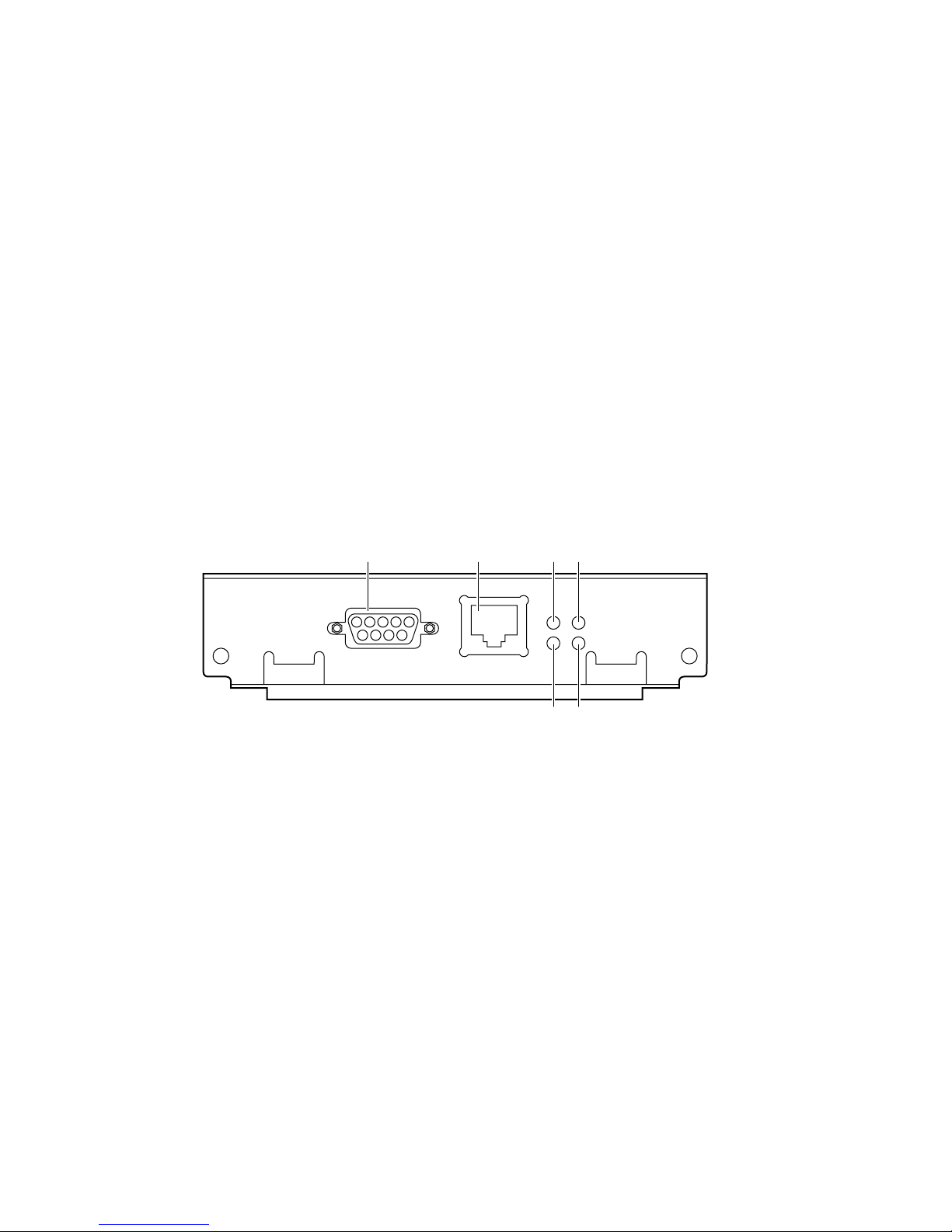
Token Ring connections and indicators
The PhaserShare Token Ring card has the following connections and indicators on the rear
panel:
Shielded Twisted Pair (STP; IBM Type 1) connector (DB-9).
Note
The STP port on the PhaserShare Token Ring card
supports cable lengths up to 150 meters (492 feet) from
the interface to the MAU (Medium Access Unit),
including lobe and patch cables.
Unshielded Twisted Pair (UTP; IBM Type 3) connector (RJ-45).
Ring speed indicator (yellow); on indicates 16 Mbps, off indicates 4 Mbps.
TX indicator (yellow); blinks while the interface is transmitting.
Connection indicator (green); on indicates that the card is asserting its ring insertion
control signal.
RX indicator (green); blinks while the interface is receiving.
1234
PhaserShare
Series B
Token Ring Card
TM
STP
UTP
Mbs
INS
16
56
TX
RX
9789-06
PhaserShare Networking Manual 3
Page 9
1.
2.
Token Ring
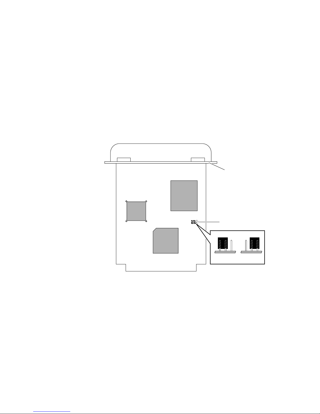
Ring speed jumper
The Token Ring card is equipped with a single three-pin jumper to set the ring speed.
There are two settings: 4 Mbps and 16 Mbps.
Note
If you received your printer with the Token Ring card already installed, you must
turn off the printer and remove the card before you change the jumper setting.
The following illustration shows a top view of the card and the location of the jumper.
Rear panel
Jumper
1
2
16 Mbps 4 Mbps
9789-03
4 PhaserShare Networking Manual
Page 10

1.
2.
3.
Token Ring
Setting Frame Routing from the front panel
(Phaser 750)
You can set the Token Ring Frame Routing from the printer’s front panel. When you have
the Frame Routing set, you may want to set other Token Ring parameters. See Setting
Token Ring parameters on page 7. See the table Token Ring parameters on page 6 for a list
of Token Ring parameters.
The choices are Transparent (no source routing) or Source Route (use source routing).
Press Menu; the front panel displays Menu Maps.
Press ----> or <---- until the front panel displays Configuration. Press Menu.
Press ----> or <---- until the front panel displays Network Settings. Press Menu.
Access the Frame Routing menu:
Press Menu until the front panel displays Token Ring.
Press Menu; the front panel displays the first of two Frame Routing choices.
Select the desired Frame Routing: Transparent or Source Route:
4.
a.
b.
5.
a.
b.
6.
Press ----> until the Frame Routing choice you want is displayed.
Press OK to enter your choice into the printer; the front panel briefly displays
Selected , then returns to the Token Ring display.
Return the printer to normal operation:
a. Press Exit until the front panel displays Network Settings.
b. Press Exit again.
PhaserShare Networking Manual 5
Page 11

Token Ring
Token Ring parameters
Parameter Description Choices
Network
Address
Speed Reports the ring speed set by the
Early Token
Release
Adapter Status Reports the Token Ring card status.
Route Cache Size The number of entries in the source
Route Cache
Timeout
Broadcast For broadcasting to all network nodes.
Unknown Route Used when the printer is searching for
Token Ring Address (by default, this
is a bit-swapped version of the
printer’s Printer ID, and it is a unique
address on the network). You can
supply a Locally Administered
Address.
jumper on the card.
The printer releases the token at the
end of the last byte transmitted (not
applicable at 4 Mbps).
The report is in two parts, separated
by a comma:
Adapter status, Details
Adapter status reports the condition
of the Token Ring card. Details
reports additional information.
route table.
The time in seconds that an entry
remains in the source route table
before being updated.
Changes the default frame type for
source route broadcasts. Broadcast is
ignored if Frame Routing is set to
Transparent.
Note: Some protocols (such as IP)
always use all routes, so they are not
affected by this parameter.
a route to a specific network node.
Changes the default frame type for
source route broadcasts. Unknown
Route is ignored if Frame Routing is
set to Transparent.
Note: Some protocols (such as IP)
always use all routes, so they are not
affected by this parameter.
Any valid Token Ring address
between 40.xx.xx.xx.xx.xx and
7F.xx.xx.xx.xx.xx.
4 Mbps or 16 Mbps.
Enabled (default) or Disabled
Adapter status:
Adapter Initializing. Card is starting
up.
Adapter Open. Card is connected to
the network.
Adapter Closed. Card is not
connected to the network.
Adapter Fault. Card is defective.
Details:
Ring OK. Ready for network
communication.
Fault. Internal error; the card is
defective.
Cable Disconnected. Cable is not
connected to the card.
Ring Error. Network problem.
Removed by network management.
The network administrator has
disabled the connection.
10 to 300.
5 to 65535.
Single Route. The printer uses
single-route broadcasts for most
source-route broadcasts.
All Routes. The printer uses
all-routes broadcasts for all
broadcasts.
Single Route. The printer uses
single-route broadcasts for most
source-route broadcasts.
All Routes. The printer uses
all-routes broadcasts for all
broadcasts.
6 PhaserShare Networking Manual
Page 12

Token Ring
Setting Token Ring parameters
■ On UNIX systems, you can use the script config-TokenRing, provided with the
printer’s network utilities software. See Using the config-TokenRing script on page 8.
■ On PCs, you can edit the PostScript utility file TOKNCFG.PS and send it to the
printer. See the README file in the UTILS directory on the printer’s CD-ROM for
details.
■ On a Macintosh, you can edit the PostScript utility file Configure Token Ring and
send it to the printer. See the ReadMe file in the Network Utilities folder on the
printer’s CD-ROM for details.
■ Windows users on NetWare networks can use the PhaserShare Administrator. See
Using the PhaserShare Administrator to configure Token Ring on page 7.
■ With a TCP/IP connection and a World Wide Web browser, you can use PhaserLink
Printer Management Software. See Using PhaserLink Printer Management Software
to configure Token Ring on page 8.
Whichever method you use, you must reset the printer to make the changes take effect.
For more information about resetting the printer, see Resetting the Printer on page 41.
Using the PhaserShare Administrator to configure Token Ring
1. In the PhaserShare Administrator Main window, select the desired printer from the
Printer List.
2. Click Configure Printer; this displays the Configure Printer dialog box.
3. In the Configure Printer dialog box, click the Token Ring tab.
4. In the Token Ring tab, set the Token Ring parameters as desired.
5. Click OK.
6. You are prompted to reset the printer. You must reset the printer before the changes take
effect. For more information about resetting the printer, see Resetting the Printer on
page 41.
PhaserShare Networking Manual 7
Page 13

Token Ring
Using PhaserLink Printer Management Software to configure
Token Ring
Once a TCP/IP connection to the printer has been established and the printer’s IP address
is set, you can visit the printer’s Status page from your web browser by entering the
printer’s URL (Uniform Resource Locator), just as you would to visit any web site. The
printer’s URL is:
http://printer’s-IP-address/
where printer’s-IP-address is the IP address or DNS name you set during TCP/IP
configuration.
Example using IP addess: http://192.1.1.1/
Example using DNS name: http://Tektronix_Marketing/
1. Connect to the printer via PhaserLink (as described in the preceding paragraphs).
2. On the left side of the page, click Settings.
3. In the INTERFACES group, click PhaserShare Token Ring Card.
4. Enter the Token Ring parameters in the fields on the page.
5. Click Apply to save your changes.
6. You must reset the printer before the changes take effect. For more information, see
Resetting the Printer on page 41.
For more information on PhaserLink, see your printer’s networking setup guide.
Using the config-TokenRing script
The UNIX shell script config-TokenRing is provided with the printer’s network utilities
software. The script creates a PostScript file containing the Token Ring parameters. Set
the Token Ring parameters by sending the PostScript file to the printer.
Before performing this procedure, you must install the script on your host computer. If
you have not already installed the file, see Extracting files from unix.tar on page 25. Your
host spooling system must also be configured; see TCP/IP Host Configuration (UNIX) on
page 25.
1. Connect the printer to the network. ARP (Address Resolution Protocol) requires that
the printer be connected on the same physical network segment as the host. You will
be using the arp command later in this procedure.
2. Log in.
3. Run the script config-TokenRing:
a. Change (cd) to the bin subdirectory in the directory where you placed your
printer’s network utilities.
b. Type the name of the script, redirecting the output to a file. Type:
config-TokenRing > filename
4. When prompted by the script, enter the Token Ring parameters.
8 PhaserShare Networking Manual
Page 14

Token Ring
5. When the script is finished, log in as root.
6. Make an entry into the host’s ARP (Address Resolution Protocol) table defining the
printer’s Printer Name/Token Ring address pair. In general, this requires a command
corresponding to one of the following syntax examples:
arp -s printer-name Token-Ring-address (for BSD systems)
or
arp -s ether printer-nam e Token-Ring-address (for System V)
See the documentation for your host system for specifics of this command.
7. Turn on the printer.
8. Use the host spooling system (for example, lpr or lp) to send the file you created in Step
3b to the printer; this stores the Token Ring information in the printer’s internal memory,
where it is retained over a reset or power cycle.
9. You must reset the printer before the changes take effect. For more information, see
Resetting the Printer on page 41.
PhaserShare Networking Manual 9
Page 15

Setting IP addressing: PostScript utility file (UNIX only)
Setting IP addressing: PostScript utility
file (UNIX only)
Use the config-IP script to create a PostScript file that sets the printer’s IP addressing
parameters. The config-IP script is provided with your printer’s network utilities software.
■ The output of the script is PostScript code, which you must send to the printer.
When you run the script, redirect the output to a file. Then send the file to the
printer.
■ The script prompts you to provide certain information. For information about these
prompts, see the next table, IP addressing parameters.
The advantage of this method is that each printer has a permanent setup stored in memory
and is not dependent on a boot server for boot information. The disadvantage is that you
must configure each printer individually.
Before performing this procedure, install the files from your printer’s network utilities
software on to your host computer. If you have not already installed the files, see
Extracting files from unix.tar on page 25.
The IP parameters are listed in the following table. For the procedure, see the next topic,
Running the config-IP script.
IP addressing parameters
Parameter Description
Use BOOTP/DHCP Yes/no. Specifies whether the printer should get its IP address from a
IP address Printer’s address on a network. Format is x.x.x.x, where x represents
Network mask Needed in networks that use sub-netting. If you are not using
Broadcast address Address the printer uses to send broadcast packets. Format is x.x.x.x,
Default gateway (router) Address the printer uses to communicate with devices not on the
BOOTP or DHCP response at power-up (default is yes). Answer
for a printer-based configuration; this prevents BOOTP or DHCP
packets from appearing on the network when the printer is turned on
or reset.
a decimal number from 0 - 255. Must be a valid IP address and not
0.0.0.0, 255.0.0.0, any address starting with 127, or any address
ending with 255.
sub-netting, leave this blank; the printer will choose an appropriate
mask. Format is x.x.x.x, where x represents a decimal number from 0
- 255.
where x represents a decimal number from 0 - 255. If you are unsure,
leave this blank; the printer chooses an appropriate address.
same network segment. Format is x.x.x.x, where x represents a
decimal number from 0 - 255.
no
10 PhaserShare Networking Manual
Page 16

Setting IP addressing: PostScript utility file (UNIX only)
Running the config-IP script
1. Connect the printer to a network. ARP (Address Resolution Protocol) requires that
the printer be connected on the same physical network segment as the host.
2. Run the script config-IP:
a. In the directory where you placed your printer’s network utilities, change (cd) to
the bin subdirectory.
b. Type the name of the script, redirecting the output to a file. Type:
config-IP > filename
3. Enter the information when prompted by the script.
Note
The script accepts IP addresses that have empty fields (for example,
123..40.10). The script does not detect this error. Double-check the IP
addresses you enter.
4. Log in as root.
5. Make an entry into the host’s ARP table defining the printer’s IP/hardware address
pair. In general, this requires a command corresponding to one of the following
examples:
arp -s printer-IP-address hardware-address (for BSD systems)
or
arp -s ether printer-IP-address hardware-address (for System V)
See your host system documentation for specifics of this command.
Note
The hardware address in the arp command example is the printer’s
Ethernet Address for PhaserShare Ethernet interfaces or the Token Ring
Address for PhaserShare Token Ring cards.
6. Turn on the printer.
7. Execute the ping command from the host:
ping printer-IP-address
8. Use the host spooling system (for example, lpr or lp) to send to the printer the file you
created in Step 2b. This stores the IP addressing information in the printer’s internal
memory, where it is retained over a reset or power cycle. (For more information on
setting up queues, see TCP/IP Host Configuration (UNIX) on page 25.)
9. Reset the printer.
PhaserShare Networking Manual 11
Page 17

Windows NT (non-Intel computers)
Windows NT (non-Intel computers)
These procedures are valid for Windows NT version 3.x and 4.x. For information about
driver installation for later versions of Windows NT, contact Tektronix technical support
or visit the Tektronix web site:
www.tek.com/Color_Printers/support/
Setting the printer’s IP address
There are three ways to set the printer’s IP address:
■ Use the printer’s front panel. For more information, see your printer’s networking
setup guide.
■ Use DHCP. For more information, see your printer’s networking setup guide.
■ Download a PostScript utility file. For more information, see the README file on the
printer’s CD-ROM. The README file is in the UTILS directory.
Adding the Windows NT 4.0 driver on a Windows
NT 4.0 server or workstation
The Windows NT 4.0 PostScript driver is a PPD-based driver. Follow these instructions to
add or update the Tektronix Phaser PPD for use with Windows NT 4.0. Adding this
support gives your printer access to Tektronix page sizes, tray selection, TekColor color
corrections, and resident fonts.
This update procedure provides printer page-size information for Windows NT
applications. These instructions assume a basic familiarity with Windows NT operation
and terminology. For additional information about Windows NT, refer to your Microsoft
Windows NT documentation.
Note
You may need the Windows NT 4.0 CD-ROM or your printer’s software CD-ROM
to complete this procedure.
12 PhaserShare Networking Manual
Page 18

Windows NT (non-Intel computers)
Add the printer
1. Log in as Administrator or a user with administrator privileges.
2. Click Start, Settings, and Printers.
3. In the Printers dialog box, double-click Add Printer.
■ If you intend to do your printer management from this computer, click My
Computer. The rest of this procedure applies when you click My Computer.
■ If you intend to do your printer management from another computer, click
Network Print Server. In this case, you need only enter the printer’s name in the
Printer field and click OK. The rest of this procedure does not apply.
4. Click Next.
5. If the printer is connected directly to the computer, select the port the printer is
connected to:
a. LPTx is for a parallel-printer connection.
b. COM is for a serial-connected printer.
6. If the printer is connected to a network, click Add Port. Tektronix printers support two
types of network ports, LPR and AppleTalk. The next topic covers LPR ports; for
information on AppleTalk ports, see Creating an AppleTalk port on page 14.
Creating an LPR port
1. To connect via TCP/IP, double-click LPR Port in the Printer Ports dialog box. If LPR
Port is not listed in this box, the Microsoft TCP/IP Printing Service must be installed
on the NT machine:
a. Click Start, Settings, Control Panel, and Network.
b. Click Services, then click Add.
c. Select Microsoft TCP/IP Printing, then click OK and install this service. The
original Windows NT distribution CD-ROM is needed during installation.
Note
The TCP/IP protocol must also be installed on the server. Click the Protocol
tab to verify if it is installed. See your Windows NT documentation for
details. Reboot Windows NT after installing TCP/IP.
2. In the Add LPR compatible printer dialog box, enter the printer's IP address or DNS
name in the box labeled Name or address of server providing lpd. In the box marked
Name of printer or print queue on that server, enter PS or AUTO in uppercase. Click
OK.
3. When returned to the Printer Ports box, click Close.
4. At the Add Printer Wizard dialog box, click the box next to this new port; a check mark is
added. Click Next.
PhaserShare Networking Manual 13
Page 19

Windows NT (non-Intel computers)
Creating an AppleTalk port
1. In the Printer Port dialog box, double-click AppleTalk Printing Devices.
2. In the Available AppleTalk Printing Devices dialog box, select the zone where the
printer resides. If no zone name appears, double-click the zone icon.
3. Windows NT searches for all AppleTalk devices in that zone and displays a list;
double-click your printer.
4. Windows NT prompts you to capture the printer; click No. (Capturing the printer causes
it to disappear from the Chooser.)
5. After adding the printer port, click the box next to the new port to select it; click Next.
Install the driver
1. In the Add Printer Wizard dialog box, click Have Disk to add a new Tektronix driver.
2. Type the path name to the driver files. This can be A:\ if the files are on a diskette. If
these files were downloaded from an on-line service, type the path name where they
were saved. Click OK.
3. Select the printer model and click Next.
4. If prompted that a driver is already installed for this printer, select Replace existing
driver. Click Next.
Name the printer and set up sharing
1. Type the printer's name; this can be any name you want. If the Windows-based
applications are to use this printer as the default printer, click the appropriate box.
Click Next.
2. If this printer is to be shared on the network, click Shared and click all applicable
platforms that may be printing to this printer. If desired, enter a Share Name for the
printer. If the printer is a local printer only, click Not shared. Click Next.
Windows NT creates the printer
1. If you want Windows NT to print a test page after installing the printer driver, click
Yes (recommended). If you do not want the Windows NT test page, click No. When
finished, click Finish.
2. At this point, Windows NT is ready to create the printer. You may need the original
Windows NT distribution CD-ROM or your printer’s software CD-ROM to complete this
step. Once the CD-ROM is installed, type the drive letter or path name to the files
requested. On the Windows NT CD-ROM, the files are usually in the I386 directory for
Intel-based Windows NT servers. Click OK.
3. If you chose to have a test page printed in Step 1, check to see if it printed. If the test page
printed, click OK.
14 PhaserShare Networking Manual
Page 20

Windows NT (non-Intel computers)
Adding the Windows NT 4.0 driver on a
Windows NT 3.51 server
Note
For proper installation, use the latest Windows NT 3.51 drivers and
Windows NT 4.0 drivers, available from the Tektronix web site
www.tek.com/Color_Printers/support/
The following procedure describes how to set up the Windows NT 3.51 server to
automatically load a Windows NT 4.0 driver on a Windows NT 4.0 client.
Note
You must have Administrator access on the Windows NT 3.51 server.
Add the printer
1. From a Windows NT 4.0 client, click the right-mouse button on Network
Neighborhood. Select Find Computer.
2. Type the name of the Windows NT 3.51 server. Press Enter.
3. Double-click the Windows NT 3.51 server icon.
4. Double-click the Windows NT 3.51 server's Printers folder.
5. In the Windows NT 3.51 server's Printers folder, double-click Add Printer. (If you do
not have an Add Printer icon, then you are not logged on with an account that has
Administrator access on the Windows NT 3.51 server.) The first Add Printer Wizard
dialog box should say Remote print server <3.51 server name>.
6. Select the port where the printer is connected.
Note
You cannot create a port on the Windows 3.51 server from the Windows 4.0
client; create the port on the Windows 3.51 server. After the port is created,
you can select that port from the Windows 4.0 client.
Install the driver
1. In the Add Printer Wizard dialog box, click Have Disk to add a new Tektronix driver.
2. Type the path name to the driver files. This can be A:\ if the files are on a diskette. If
these files were downloaded from an on-line service, type the path name where they
were saved. Click OK.
3. Select the printer model and click Next.
PhaserShare Networking Manual 15
Page 21

Windows NT (non-Intel computers)
Enter the printer’s name and set up sharing
1. Type the printer's name; this can be any name you want. Click Next.
2. If this printer is to be shared on the network, click Shared and highlight all applicable
platforms that may be connecting to this server (Windows NT 4.0 x86 should be one). If
desired, enter a Share Name for the printer.
Windows NT creates the printer
1. If you want Windows NT to print a test page after installing the printer driver, click
Yes (recommended). If you do not want the Windows NT test page, click No. When
finished, click Finish.
2. When prompted for the Windows NT 3.51 CD-ROM, insert it into your computer’s
CD-ROM drive and click OK.
3. Type the path name to the driver.
Note
For proper installation, you must use the latest Windows NT 3.51 drivers
and Windows NT 4.0 drivers, which are available from the Tektronix web
site:
www.tek.com/Color_Printers/support/software.html
The printer should now exist on the Windows NT 3.51 server and have Windows NT 4.0
drivers available. Now any Windows 4.0 client can use that shared printer, and the driver
is installed automatically.
Adding a Windows NT 3.x driver
This update procedure provides printer page size information for Windows NT
applications. However, TekColor color corrections and other PostScript Level 2 features
are not supported by the Windows NT driver. Refer to your printer’s user documentation
for instructions on other ways of selecting color corrections. Refer to your Microsoft
Windows NT documentation for details on features in the Windows NT driver.
These instructions assume a basic familiarity with Windows NT operation and
terminology. For additional information about Windows NT, refer to your Microsoft
Windows NT documentation.
1. Start your system with Windows NT.
2. From the Main window, double-click the Print Manager icon.
3. Install the Tektronix printer. From the Printer menu, select Create Printer; the Create
Printer dialog box appears.
4. Under Driver, scroll to the end of the list and select Other; the Install Driver dialog box
appears.
16 PhaserShare Networking Manual
Page 22

Windows NT (non-Intel computers)
5. When prompted, do one of the following.
■ If you are using the printer’s CD-ROM: Type the CD-ROM drive location. Click
OK; the Select Driver dialog box appears.
■ If you are using the printer’s software for Windows diskette: Type the diskette
drive location. Click OK; the Select Driver dialog box appears.
6. Under Printer Driver, choose your printer from the list, then click OK.
Note
If you are using older drivers, you get a series of Noncritical Errors stating
that Windows NT is unable to open the PSCRIPT.DLL file and the
PSCRIPT.DRV files. Click Ignore or update your driver.
7. Under Print to, scroll to the end of the list and select Other; the Printer port dialog box
appears. Tektronix printers support two types of network ports in Windows NT: LPR
and AppleTalk. The next topic covers LPR ports; for information on creating an
AppleTalk port, see Creating an AppleTalk port on page 18.
Creating an LPR port
1. In the Printer Port dialog box, click the LPR port. If the LPR port is not listed in the
Printer Port dialog box, the Microsoft TCP/IP Printing Service needs to be added to
the Windows NT machine:
a. In the Control Panel, double-click Network; the Network Settings dialog box
appears.
b. In Network Settings, click Add Software; the Add Network Software dialog box
appears.
c. In the Add Network Software dialog box, click the drop-down menu for
Network Software. In the list, select TCP/IP Protocol and Related Components,
then click Continue; the TCP/IP Installation dialog box appears.
d. In the TCP/IP Installation dialog box, select TCP/IP Network Printing Support.
(Consult your Windows NT documentation for information on other TCP/IP
options.)
e. Click Continue to install this service. The original Windows NT distribution
diskettes are needed during installation. To apply these changes, restart
Windows NT.
2. In the Add LPR compatible printer dialog box, enter your printer’s IP address in the
field named Name or address of server providing lpd. In the field named Name of
printer or print queue on that server, enter PS or AUTO in UPPERCASE letters.
PhaserShare Networking Manual 17
Page 23

Windows NT (non-Intel computers)
Creating an AppleTalk port
1. In the Printer Port dialog box, double-click the AppleTalk Printing Devices port. If
the AppleTalk Printing Devices port is not listed in the Printer Port dialog box, the
Microsoft Services for Macintosh needs to be added to the Windows NT machine:
a. In Control Panel, double-click Network; the Network Settings dialog box
appears.
b. In the Network Settings dialog box, click Add Software; the Add Network
Software dialog box appears.
c. In the Add Network Software dialog box, click the drop down menu for Network
Software. In the list, select Services for Macintosh, then click OK to install the
service. The original Windows NT distribution diskettes are needed during
installation. To apply these changes, restart Windows NT.
2. In the Available AppleTalk Printing Devices dialog box, select the zone where the
printer resides. If no zone name appears, double-click the zone icon.
3. Windows NT searches for all AppleTalk devices in that zone and displays a list;
double-click your printer.
4. Windows NT prompts you to capture the printer; click No. (Capturing the printer causes
it to disappear from the Chooser.)
Set up sharing
If this printer is to be shared on the network, perform the following steps:
1. In the Create Printer dialog box, check the option Share this printer on the network.
2. Enter any name you want for the Share Name.
18 PhaserShare Networking Manual
Page 24

Windows NT (non-Intel computers)
Windows NT network communication
Basic concepts of TCP/IP printing
In Windows NT, printing via TCP/IP is accomplished using the LPR (Line Printer Request)
protocol. Because LPR was developed for UNIX systems, comparing Windows NT and
UNIX implementations may be helpful.
The LPR protocol is a host-to-host protocol, rather than a host-to-printer protocol. When
printing via LPR, the computer sending the print job assumes that it is sending the job to
another computer, or print server, which sends the job to the printer. In UNIX
terminology, the print server is called a remote host. The print server can have several
printers connected to it. The way to differentiate between different printers when
spooling to the print server is to print to a specific remote queue.
The following table summarizes these concepts of TCP/IP printing and the terminology
used in UNIX and Windows NT environments.
Concept Description UNIX term NT term
Print server An IP address or a DNS name
that is mapped to this address.
This is how your computer
knows where to send the print
job.
Print queue For Tektronix printers, this is PS
(PostScript) or AUTO
(AutoSelect).
Remote host Name or
Remote printer
queue name
address of host
providing LPD
Name of
printer on that
machine
Your Tektronix printer emulates a print server. Tektronix printers are accessed by giving
an NT host a remote host name that will point to the printer. This is true only if the print
job is spooled directly to the printer via its internal network interface, and not through an
external third-party print server. If the print job is spooled through an external third-party
print server, the remote host name is the TCP/IP address of the print server and the remote
queue name is the name of the queue for that print server.
PhaserShare Networking Manual 19
Page 25

Windows NT (non-Intel computers)
Windows NT network troubleshooting
Error messages in Print Manager
When there is a problem printing from Windows NT, often print jobs stay in Print Manager
with ambiguous messages like Printer Error or Permission denied. If the printer is
connected via TCP/IP, there is probably a problem with the way LPR was set up.
Begin troubleshooting by opening the Event Viewer in the Administrative Tools program
group. When it opens, click Log, scroll down, and select Application. Look at any of the
error messages that say LPR Print Monitor. Double-clicking the error message tells you
more information about the error. The following topics deal with specific errors reported
in the Event Viewer.
Printer PS on host IP-address is rejecting your request
At the MS-DOS command prompt in Windows NT, type the ping command in the
following format:
ping IP-address
For example:
ping 192.1.1.2
■ If the printer does not reply or the request times out, either the printer does not have
an IP address, or the NT host cannot find the printer.
■ If the printer does not have an address, assign one as described in your printer’s
networking setup guide.
■ If the printer has an IP Address, your printer could have a faulty network
connection or a defective network card.
■ If the printer does respond, disconnect the printer from the network and send the
ping command again.
■ If you get a response this time, there is a duplicate IP address on the network.
Make sure that all devices on the network have a unique IP address.
■ If you do not get a response this time, the printer's IP address is valid, but LPR
may be disabled on the printer. Print a Configuration Page and look under LPR.
For instructions on how to print a Configuration Page and enable protocols, see
your printer’s networking setup guide.
20 PhaserShare Networking Manual
Page 26

Windows NT (non-Intel computers)
Printer printer-name on host IP-address is rejecting your request
The remote queue name is not correctly set. Refer to Step 2 in the appropriate procedure:
■ Windows NT 4.0 driver on Windows NT 4.0 server. See Creating an LPR port on
page 13.
■ Windows NT 3.x driver. See Creating an LPR port on page 17.
Printer PS on host IP-address is unreachable
or
The LPR print monitor failed to open a temporary file while
spooling output for port IP-address:PS
With this problem, you can print all PostScript jobs when logged into the NT Server as
administrator, but users cannot print. Users cannot print because they lack the
permissions to spool to the system file areas.
This problem is frequently encountered after applying Service Pack 2, 3, or 4 to a
Windows NT 3.51 print server installed on an Windows NT File System (NTFS) partition.
Windows for Workgroups, Windows 95, and other clients will no longer be able to print to
shared LPR printers (print queues on Windows NT which are using LPR to reach their
destination).
Service Pack updates change the permissions of the SPOOL and PRINTERS sub-directories
to be read-only (write-protected). Also, an administrator could easily do this (for security
reasons) without a Service Pack Update.
To fix this problem in Windows NT 4.0:
1. Log in as administrator.
2. Double-click My Computer.
3. Open the folder C:\Winnt\system32.
4. Set permissions on the spool folder:
a. Click the right mouse button on the spool folder.
b. In the pull-down menu, click the left mouse button on Sharing; this displays the
Printer Properties dialog box.
c. Click Security.
d. Click Permissions; this displays the Directory Permissions dialog box.
e. In the Directory Permissions dialog box, click Everyone. From the Type of
Access pull-down list, select Full Control.
f. To close the Directory Permissions dialog box, click OK.
g. To close the Printer Properties dialog box, click OK.
PhaserShare Networking Manual 21
Page 27

Windows NT (non-Intel computers)
5. Set permissions on the Printers folder:
a. In the C:\Winnt\system32 folder, open the spool folder.
b. Click the right mouse button on the Printers folder.
c. In the pull-down menu, click the left mouse button on Sharing; this displays the
spoolProperties dialog box.
d. Click Security.
e. Click Permissions; this displays the Directory Permissions dialog box.
f. In the Directory Permissions dialog box, click Everyone. From the Type of
Access pull-down list, select Full Control.
g. To close the Directory Permissions dialog box, click OK.
h. To close the spoolProperties dialog box, click OK.
To fix this problem in Windows NT 3.1:
1. Log in as administrator.
2. In the Main group, double-click File Manager.
3. Open the folder C:\WINNT35\system32.
4. Set permissions on the spool folder:
a. Click the spool folder.
b. From the Security menu, select Permissions; this displays the Directory
Permissions dialog box.
c. In the Directory Permissions dialog box, click Everyone. From the Type of
Access pull-down list select Full Control.
d. To return to File Manager, click OK.
5. Set permissions on the Printers folder:
a. In the C:\WINNT35\system32 folder, open the spool folder.
b. Click the Printers folder.
c. From the Security menu, select Permissions; this displays the Directory
Permissions dialog box.
d. In the Directory Permissions dialog box, click Everyone. From the Type of
Access pull-down list, select Full Control.
e. To return to File Manager, click OK.
22 PhaserShare Networking Manual
Page 28

Windows NT (non-Intel computers)
Printing from the command line via lpr
To send a PostScript file to the printer using lpr, type the following lpr command in at the
MS-DOS command prompt in Windows NT:
lpr -S IP-address -P PS filename
For example:
lpr -S 134.62.36.161 -P PS FONTS.PS
■ If you get the following message, your printer is spooling to the wrong IP address, LPR
is disabled on the printing device, or LPR on the printing device is denying access:
Error: print server did not accept request.
Job aborted.
■ If you get the following message, the printer has TCP/IP disabled or your printer is
spooling to an invalid IP address:
Error: print server unreachable or specified
printer does not exist.
Print a Configuration Page and make sure that TCP/IP is still
enabled. For instructions on how to print a Configuration Page
and enable protocols, see your printer‘s networking setup guide.
Check to see if your printer is spooling to a correct IP address.
Note
When using the lpr command at a DOS command
prompt when the Name of the print queue is not PS,
this message is displayed: Error: print server did not
accept request. Job aborted.
Checking the IP address of the Windows NT server
If you have tried the techniques described in this troubleshooting topic and
communication is still not happening, check the IP address of the Windows NT server. If
it is in a different class (possibly even a different network number in the same class), it can
prevent communication from taking place.
PhaserShare Networking Manual 23
Page 29

Novell NetWare (DOS)
Novell NetWare (DOS)
The printer’s CD-ROM contains a DOS application, NWSET, that can be used for
configuration in DOS environments. For information on how to use NWSET, see the
README file in the NETWARE directory on the printer’s CD-ROM and network utilities
diskettes.
■ NWSET (Tektronix). Use this application to configure the printer with NetWare 3.x
and 4.x. For more information on NWSET, see the README file in the NETWARE
directory of the printer’s or CD-ROM.
■ NWCONFIG.PS (Tektronix utility file). In DOS environments and other
non-Windows environments, you can use this to configure the printer for NetWare 4.x
networks. The PostScript code contained in the file NWCONFIG.PS is also available
in a Macintosh file called Configure NetWare. For more information on
NWCONFIG.PS, see the README file in the UTILS directory of the printer’s or
CD-ROM. For more information on Configure NetWare, see the ReadMe file in the
Network Utilities directory of the printer’s or CD-ROM.
■ PCONSOLE (Novell). Use this utility to manage existing queues with NetWare 3.x
and 4.x (both Bindery and NDS modes).
24 PhaserShare Networking Manual
Page 30

TCP/IP Host Configuration (UNIX)
TCP/IP Host Configuration (UNIX)
Extracting files from unix.tar
The file unix.tar contains all shell scripts and other files needed for network configuration
in UNIX environments. The file is in UNIX tar format. The file is included with your
printer’s networking software.
Listing the contents of unix.tar
Type this command:
tar tvf /directory-name/unix.tar
Where directory-name is the mount point or the directory that contains the file. For
example:
tar tvf /mnt/unix.tar
Extracting the files
1. Change (cd) to the directory on your workstation where you want the files to reside.
2. Type this command:
tar xvf /directory-name/unix.tar
Where directory-name is the mount point or the directory that contains the file. For
example:
tar xvf /mnt/unix.tar
Adding the printer to the host table
Add the printer’s name to the host table and assign an IP address to the printer’s name.
Depending on your host system, you may do this one of three ways:
■ Use NIS (Name Information Server, formerly Yellow Pages).
■ Use DNS (Domain Name Server).
■ Edit a file (for example, /etc/hosts). For an example, see Example installation for a
typical BSD UNIX system on page 27.
PhaserShare Networking Manual 25
Page 31

TCP/IP Host Configuration (UNIX)
Assigning a print queue to the printer
■ For BSD systems, edit the /etc/printcap file and add a spool directory (for example, to
/usr/spool/lpd).
■ For System V hosts, configure the queue as a remote BSD print queue (support for
TCP/IP LPR is required). Specific instructions for the following System V hosts are
provided in this manual:
■ Sun Solaris on page 30.
■ SGI IRIX 5.3 and 6.x on page 32.
■ IBM AIX 3.x and 4.x on page 33.
■ Hewlett-Packard HP-UX 9.x and 10.x on page 35.
Note
Some UNIX hosts report an error when you configure a print queue that is not
currently on the network; ignore this message.
Assigning print queues with PhaserPrint for UNIX
For UNIX environments, Tektronix offers PhaserPrint for UNIX software, which provides
fast raster printing and a graphical user interface with push-button control of printer
features. For more information on PhaserPrint software, see your printer’s networking
setup guide.
If you want to print using PhaserPrint for UNIX software, you must use PhaserPrint
software to configure your host. Refer to the PhaserPrint for UNIX user manual or the
instructions provided with the PhaserPrint for UNIX CD-ROM for configuration
information. A PDF version of the manual is available from the Tektronix ftp site:
ftp.tek.com/cpid/UNIX/phaserprint2.1/demo/MANUALS
Required remote printer queue names
The printer’s internal LPR queue uses the BSD protocol; its known queues are listed in the
following table. These are the only remote queue names that the printer recognizes. If you
use another name, the printer automatically defaults to AUTO.
Queue name Language
PS PostScript
PCL PCL (Printer Control Language)
AUTO Automatic Language Selection (the printer automatically senses
the language of the print job and processes it accordingly)
26 PhaserShare Networking Manual
Page 32

TCP/IP Host Configuration (UNIX)
Using PostScript utility files to control printer features from queues
As you set up a spool queue for the printer, you can use the PostScript utility files
provided with your printer’s software to control printer features (for example, selecting
upper or lower paper trays, or selecting print quality modes). See your printer’s user
documentation for more information on these utility files.
UNIX model files
The printer’s CD-ROM contains UNIX model files. These files allow you to access printer
features from the UNIX command line by using the -o printing option. On the printer’s
CD-ROM, the file model.tar contains the installer for the model files and model files for
Sun Solaris, Hewlett-Packard, and IBM AIX workstations.
Example installation for a typical BSD UNIX system
The following procedure is an example spooler configuration that will work for many
BSD systems, including SunOS 4.x and 5.x (Solaris 1.x and 2.x) and Digital UNIX.
Modify the /etc/hosts file to identify the printer to the workstation and modify the
/etc/printcap file to describe the printer to the workstation:
1. Log on to your system as root.
2. Make a backup copy of the /etc/hosts file.
Note
You need superuser privileges to edit this file.
3. Edit /etc/hosts and add a line that defines the printer's IP address and its name. The IP
address you enter here for the printer must be the same address you specified as the
printer's IP address when it was configured. The name is the name by which your
workstation identifies the printer. (You will enter this same remote name in your
/etc/printcap file in the next step.)
Example
192.1.1.2 Phaser850
In this example, 192.1.1.2 is the printer’s IP address and Phaser850 is the
printer’s remote name.
4. Make a backup copy of the /etc/printcap file.
PhaserShare Networking Manual 27
Page 33

TCP/IP Host Configuration (UNIX)
5. Edit /etc/printcap and add an entry for your printer. Refer to the following example and
the table Descriptions of printcap parameters on page 29 to create your entry.
Sample printcap file
# Printer: Tektronix Phaser850
# Print queue name: colorprinter
# Remote machine name: Phaser850
# Remote printer queue name: PS
# Spool directory: /usr/spool/lpd/colorprinter
colorprinter:\
:lp=:\
:rm=Phaser850:\
:rp=PS:\
:mx#0:\
:lf=/usr/spool/lpd/ERRORLOG:\
:sd=/usr/spool/lpd/colorprinter:
#
6. Set up spool directories. After you have edited the /etc/hosts and /etc/printcap files, create
and set permissions for the spool directory you specified.
Example
cd /usr/spool/lpd
mkdir colorprinter
chown daemon colorprinter
chgrp daemon colorprinter
chmod 770 colorprinter
Refer to your UNIX documentation for the correct command syntax for your
workstation.
28 PhaserShare Networking Manual
Page 34

TCP/IP Host Configuration (UNIX)
Descriptions of
printcap
parameters
Parameter Description
lp Name of the device to open; this parameter must be left empty or set to
/dev/null.
rm Remote machine name. This is the name by which the workstation identifies
the printer; it must match the name in the /etc/hosts file.
rp Remote printer queue name. This is the queue name that the printer
recognizes. It must be one of the following:
■ PS for PostScript
■ PCL for Printer Control Language
■ AUTO for Automatic Language Selection (the printer automatically senses
the language of the print job and processes it accordingly)
If you specify any other remote printer queue name, the printer defaults to
AUTO.
Your printer model may not support all languages listed here. See your
printer’s user documentation for information on the supported languages.
With some printers, PCL must be authorized with an authorization code
before it can be used. If you use PCL for the remote printer queue name,
make sure that PCL has been authorized in the printer. See your printer’s
user documentation for more information on authorization codes and PCL.
mx Maximum file size. Set this parameter to 0 for unlimited file size; this allows
the print command to handle large PostScript or image files.
lf Name of the log file where print command error messages are collected.
Some systems have a log file for each print queue. Refer to your
workstation’s documentation for more information.
sd Spool directory on your host. Make a separate spool directory for each
queue.
PhaserShare Networking Manual 29
Page 35

TCP/IP Host Configuration (UNIX)
Configuration procedures for common System V
UNIX hosts
Sun Solaris
For Solaris version 2.6 and later, go to Adding an LPD queue in Solaris on page 31. For
Solaris 2.5x and older, use the sol_apps.tar provided with your printer’s networking
software to avoid a Solaris communication problem. The sol_apps.tar file is also available
from the Tektronix ftp site:
ftp.tek.com/cpid/UNIX/sun/sol_apps.tar
This file redirects the print jobs to the printer's AppSocket port (port 9100) instead of the
LPD port (port 515).
Note
If you do not want to redirect the print jobs to the printer's AppSocket port, see
Adding an LPD queue in Solaris on page 31.
1. Untar the sol_apps.tar file by typing this command:
tar -xvf phaser.sun5
The following files are extracted into the indicated directories:
asprint.sun5 to /usr/bin
tektcp.sun5 to /usr/spool/lp/model
2. Edit the file /etc/hosts to create an entry for the printer.
Note
The network name and the queue name for your printer must be identical
for the model file to work.
3. Execute the following commands:
lpadmin -p queuename -v /dev/null -i /usr/spool/lp/model/tektcp.sun5 -I postscript
enable queuename
accept queuename
where queuename is the name entered for the printer in the /etc/hosts file.
The print queue is now enabled.
30 PhaserShare Networking Manual
Page 36

TCP/IP Host Configuration (UNIX)
Adding an LPD queue in Solaris
Add the printer to the host table. This is done by either editing the local host table
/etc/hosts (if not running yp or NIS), or updating the NIS data base on the NIS (yp) server.
Here is an example of how to add a PostScript queue named phaser printing to a printer
named tektronix while in the Bourne shell.
/bin/sh
lpsystem -t bsd tektronix
lpadmin -p phaser -s tektronix!PS -I postscript
The queue name can be anything you want. The printer name should be the same name
used in the host table.
The !PS names the remote printer queue name. There are four valid remote printer names:
PS, HPGL, PCL, and AUTO.
Use the following commands to enable the new queue:
lpshut /usr/lib/lpsched
enable phaser
accept phaser
If Solaris 2.2/2.3 print jobs get stuck in the queue
1. Change directory (cd) to this location:
/usr/spool/lp/temp/workstation-name
2. To remove any jobs, type:
rm
3. Change directory (cd) to this location:
/usr/spool/lp/requests/workstation-name
4. To remove any jobs, type:
rm
5. Type:
kill -pid
where pid is the process ID number /usr/lib/lpsched.
6. To restart lpsched, type:
/usr/lib/lpsched
7. Remove any jobs that have not printed from the Print Tool.
PhaserShare Networking Manual 31
Page 37

TCP/IP Host Configuration (UNIX)
SGI IRIX 5.3 and 6.x
Modify the /etc/hosts file to identify the printer to the workstation:
Note
You need superuser privileges to edit this file.
1. Log onto your system as root.
2. Make a backup copy of the /etc/hosts file.
3. Edit /etc/hosts and add a line that defines the printer's IP address and its name. The IP
address you enter here for the printer must be the same address you specified as the
printer's IP address when it was configured. The name is the name by which your
workstation identifies the printer.
IRIX 5.3 and IRIX 6.x with Impressario Client
The following procedure describes how to use the SGI Printer Manager program to
configure a workstation running IRIX 5.3 and IRIX 6.x with Impressario Client to support a
color PostScript printer.
1. From the Toolchest, click System/Printer Manager, or type printers at the command
line.
2. Click Printer, then select Add from the pull-down menu.
3. Fill in the fields (refer to the following table). Click OK.
Field name Description
New Printer Name Name of the print queue (this can be anything).
Connection Type Select Network.
Remote Host Name The name that you entered in your /etc/hosts file
Remote Printer Queue Name Queue name that the printer recognizes:
as the remote machine name.
■ PS for PostScript
■ PCL for text
■ HPGL for HP7475A
■ AUTO for automatic selection.
32 PhaserShare Networking Manual
Page 38

TCP/IP Host Configuration (UNIX)
IRIX 6.x with Impressario Server
The following procedure describes how to use the SGI Printer Manager program to
configure a workstation running IRIX 6.x with Impressario Server to support a color
PostScript printer.
1. From the Toolchest, click System/Printer Manager, or type printers at the command
line.
2. Click Printer and select Add from the pull-down menu.
3. Fill in the fields (refer to the following table). Click OK.
Field name Description
New Printer Name Name of the print queue (this can be anything).
Printer Connected To Select Local Host.
Location Code Optional; may contain information describing
Location Description Optional; may contain information describing
Printer Type Select one of the Generic Color PostScript
Printer is Attached to Select Network.
Printer's Name (or IP Address) The name that you entered in your /etc/hosts file
Printer is Attached to Network With Network card Installed in printer.
the location of the printer.
the location of the printer.
entries.
as the remote machine name.
IBM AIX 3.x and 4.x
Modify the /etc/hosts file to identify the printer to the workstation:
1. Log onto your system as root.
2. Make a backup copy of the /etc/hosts file.
Note
You need superuser privileges to edit this file.
3. Edit /etc/hosts and add a line that defines the printer’s IP address and its name. The IP
address you enter here for the printer must be the same address you specified as the
printer's IP address when it was configured. The name is the name by which your
workstation identifies the printer.
PhaserShare Networking Manual 33
Page 39

TCP/IP Host Configuration (UNIX)
AIX 3.x
The following procedure describes how to use the AIX System Management program
(SMIT) to configure a workstation running AIX 3.x to support a color PostScript printer.
1. Log in as root on your workstation.
2. From the command line, type smit.
3. Select Devices.
4. Select Printer/Plotter.
5. Select Manage Remote Printer Subsystem.
6. Select Client Services.
7. Select Remote Printer Queues.
8. Select Add a Remote Queue.
9. Fill in the fields (refer to the following table). To process the information, press Enter.
Make sure that SMIT finishes with an OK in the upper left corner. To return to the first
Printer/Plotter Devices menu, press F3.
Field name Description
NAME of queue to add Name of the print queue (this can be anything).
DESTINATION HOST for remote
jobs
Name of QUEUE on remote
printer
NAME of device to add Any name.
The name that you entered in your /etc/hosts file
as the remote machine name.
The queue name that the printer recognizes:
■ PS for PostScript
■ PCL for text
■ HPGL for HP7475A
■ AUTO for automatic selection.
AIX 4.x
The following procedure describes how to use the AIX System Management program
(SMIT) to configure a workstation running AIX 4.x to support a color PostScript printer.
1. Log in as root on your workstation.
2. From the command line, type: smit.
3. Select Print Spooling.
4. Select Add a Print Queue.
34 PhaserShare Networking Manual
Page 40

TCP/IP Host Configuration (UNIX)
5. Fill in the fields (refer to the following table). To process the information, press Enter.
Make sure that SMIT finishes with an OK in the upper-left corner. To return to the first
Printer/Plotter Devices menu, press F3.
Field name Description
Attachment Type Select remote.
Type of Remote Printing Select Local filtering before sending to
Remote Printer Type Select Other, then generic.
Name of NEW print queues to add Use the down-arrow key to move down to
HOSTNAME of remote server The name that you entered in your
Name of QUEUE on remote server Queue name that the printer recognizes:
TYPE of print spooler on remote
server
Send PASS-THROUGH FLAG to
queue on remote server?
print server.
PostScript, then enter the print queue name
on the right side. This can be anything.
/etc/hosts file as the remote machine name.
■ PS for PostScript
■ PCL for text
■ HPGL for HP7475A
■ AUTO for automatic selection.
Press F4 and select BSD.
Select F4 and select no.
Hewlett-Packard HP-UX 9.x and 10.x
1. Log in as root on your workstation.
2. Make a backup copy of the /etc/hosts file.
Note
You need superuser privileges to edit this file.
3. Edit /etc/hosts and add a line that defines the printer's IP address and its remote machine
name.
The IP address you enter here for the printer must be the same address you
specified as the Tektronix printer IP address when you configured the printer.
For example:
192.1.1.2 tekphaser
In this example, 192.1.1.2 is the printer's IP address and tekphaser is the printer's
remote system name.
4. Use the HP System Administrator Manager program (SAM) to configure an HP
workstation. From the command line, type: sam.
PhaserShare Networking Manual 35
Page 41

TCP/IP Host Configuration (UNIX)
5. Perform the appropriate step for your HP-UX version:
■ Version 9.x. Highlight Printers and Plotters from the menu. Press Return or
click Open.
■ Version 10.x. Double-click the Printers and Plotters icon.
6. Perform the appropriate step for your HP-UX version:
■ Version 9.x. Highlight Printers/Plotters from the menu. Press Return or click
Open.
■ Version 10.x. Again, double-click the Printers and Plotters icon.
7. From the Actions menu, select Add Remote Printer/Plotter.
8. Fill in the fields. For example entries and descriptions, see next table, Fields. Access
SAM's help utility for additional information about these fields.
9. To save your changes, click OK at the bottom of the window.
10. When you are asked about sending a test file to the printer, type no. (It is recommended
that you do not let SAM send a test file because it may not be compatible with your
printer.)
11. Exit SAM:
a. From the File menu, select Exit.
b. Click Exit SAM.
Fields
Field name Example entry Description
Printer Name phaser360PS The name you use to access the printer.
Remote System name tekphaser The name that you entered in your
Remote Printer Queue
PS Queue name that the printer recognizes:
Name
Remote cancel model rcmodel -
Remote status model rsmodel -
Printer class (version 9.x) - Optional
Remote printer is on a
- Check the box for a BSD system.
BSD system?
You can use any name you want.
/etc/hosts file as the remote
machine name.
■ PS for PostScript
■ PCL for text
■ HPGL for HP7475A
■ AUTO for automatic selection.
36 PhaserShare Networking Manual
Page 42

TCP/IP Host Configuration (UNIX)
Troubleshooting
Testing the network connection
Execute the ping command from the host. For example, type:
ping printer-name
If the ping test to the printer-name fails, try issuing the ping command again, specifying
the printer’s IP address explicitly; type:
ping printer-IP-address
If the ping test succeeds using the printer’s IP address, but fails using the printer’s name,
check the NIS database, DNS, or /etc/hosts file to make sure that you are using the correct
name for the printer. If the ping test fails using the printer’s IP address, check the cabling
and any gateways to make sure that the printer has a working connection.
Make sure that the printer’s IP address and network mask are consistent with the IP
address and network mask of your local subnet.
PhaserShare Networking Manual 37
Page 43

TCP/IP Configuration (OS/2 Warp/LAN Server)
TCP/IP Configuration (OS/2 Warp/LAN
Server)
The PhaserShare TCP/IP interface is compatible with these environments:
■ OS/2 Warp with TCP/IP V2.0 for OS/2
■ LAN Server 3.0 or later with the TCP/IP Application Kit.
Before you begin, connect the printer to the network.
Setting the printer’s IP addressing parameters
For information on setting the printer’s IP addressing parameters, see your printer’s
networking setup guide and Setting IP addressing: PostScript utility file (UNIX only) on
page 10.
IBM TCP/IP Version 2.0 for OS/2 includes BOOTP support. Refer to your TCP/IP
documentation for installing and configuring BOOTP on a PC.
Note
In the OS/2 Warp environment, the OS/2 boot server and the printer must be on
the same Token Ring.
Edit the hosts file to create an entry that identifies the printer’s IP address and the printer
object name (to be assigned in the next topic). The hosts file is in C:\TCPIP\ETC.
Creating an LPR queue in OS/2 Warp Connect
(direct LPR connection to the printer)
OS/2 Warp Connect allows you to print directly to Tektronix printers via LPR (no server).
Note
It is important that LPRPORTD.EXE and LPD.EXE be running in the background.
You can set these to run automatically from the Autostart tab of the TCP/IP
Configuration dialog box.
1. Create a Printer Object. To do this, use the right mouse button to drag the Printer
template from the Templates folder to the desktop; this displays the Create a Printer
dialog box.
2. In the Create Printer dialog box, enter the name of the printer.
38 PhaserShare Networking Manual
Page 44

TCP/IP Configuration (OS/2 Warp/LAN Server)
3. If the driver is already installed, select the appropriate driver; if the driver is not
installed, you must install it:
a. Click Install new printer driver; this displays the Install new printer driver
dialog box.
b. In the Printer Driver Selection section, select Other OS/2 printer driver, then
specify the path to the driver. For example:
d:\os2drv
c. Click Refresh, then select the new driver from the list. Click Install and follow
the on-screen prompts.
4. Click the right mouse button on an available Pipe port (0 through 7) and select Settings
from the menu; the Settings dialog box is displayed. If ports are not selectable or are
unavailable, follow these steps:
a. Select Install Ports from Settings and enter C:\TCPIP\DLL where appropriate.
You will only have to do this if no printers were specified when TCP/IP was
installed.
b. This is where the ports that were not available can be selected: Lpt1-3, Com 1-4,
and Pipe 0-7.
c. Once ports are installed, select a Pipe, such as Pipe 1, then double-click this port.
5. In the Print Destination section, make the following entries:
■ LPD server. The printer’s IP address.
■ LPD printer. The printer’s name. The printer’s name should be either PS or
AUTO in uppercase letters. It is recommended that you leave everything else
blank.
To return to the Create Printer dialog box, click OK; then click Create.
6. Set the printer as your default printer:
a. Click the right mouse button on the printer object.
b. Click Set default, then select the new printer object.
OS/2 client-to-server setup
1. Create a network printer object:use the right mouse button to drag the Network
Printer template from the Templates folder; the Access another network printer
dialog box is displayed.
2. In the Access another network printer dialog box, make the following selections from
the list boxes:
■ Network. Network protocol.
■ Server. Name of the server for the queue.
■ Resource. Name of the queue.
3. Click OK; this creates a network printer object.
4. Click the right mouse button on the network printer icon and select Settings from the
menu; this displays the Settings dialog box.
PhaserShare Networking Manual 39
Page 45

TCP/IP Configuration (OS/2 Warp/LAN Server)
5. In the Settings dialog box, select the Printer driver tab. If the driver is already installed,
select the appropriate driver; if the driver is not installed, you must install it:
a. Click the right mouse button on any driver and select Install from the menu.
b. In the Printer Driver Selection section, select Other OS/2 printer driver, then
specify the path to the driver.
c. Click Refresh, then select the new driver from the list. Click Install.
Warp Server 4.0/Warp Connect
Warp Server is replacing OS/2 LanServer and also allows printing to Tektronix printers
via LPR.
1. Use the procedure under Creating an LPR queue in OS/2 Warp Connect (direct LPR
connection to the printer) on page 38.
2. Make the new printer available to network clients; see your OS/2 server documentation
for details.
40 PhaserShare Networking Manual
Page 46

Resetting the Printer
Resetting the Printer
Several of the network configuration procedures require you to reset the printer. There are
several ways to reset the printer:
■ Turn the printer off, then back on again.
■ With a TCP/IP connection and a World Wide Web browser, you can use PhaserLink
Printer Management Software; see Resetting the printer: PhaserLink Printer
Management Software on page 41.
■ PC and UNIX users can send the PostScript file RESET.PS from the printer’s utilities
software.
■ Macintosh users can reset the printer using the Apple Printer Utility. See Resetting
the printer using the Apple Printer Utility on page 41.
Resetting the printer by any of these methods restores the printer to its power-on
conditions (not its factory default conditions). The power-on conditions include any
custom changes made to the printer that are stored in the printer’s non-volatile memory
and are therefore persistent across printer power cycles. For example, the printer’s name
is a power-on condition that is not altered by resetting the printer.
Resetting the printer: PhaserLink Printer
Management Software
1. Enter the printer’s URL into a web browser. The printer’s URL is:
http://printer’s-IP-address/
where printer’s-IP-address is the IP address or DNS name you set during TCP/IP
configuration.
Example using IP addess: http://192.1.1.1/
Example using DNS name: http://Tektronix_Marketing/
2. On the left side of the page, click Settings.
3. In the Setup group, click Reset Printer.
For more information on PhaserLink Printer Management Software, see your printer’s
networking setup guide.
Resetting the printer using the Apple Printer Utility
Macintosh users can reset the printer using the Apple Printer Utility.
1. Locate the Apple Printer Utility, which is included with your printer’s network
utilities software.
2. Double-click the Apple Printer Utility icon; the Printer Selector window is displayed.
3. Select the zone (if applicable) and the printer. Click Open Printer; a dialog box is
displayed containing Printer Information and Printer Preferences.
4. From the Utilities menu, select Restart Printer.
PhaserShare Networking Manual 41
Page 47

FTP Interface
FTP Interface
Your printer’s FTP interface is a standard FTP server. Using FTP, you can send a job to the
printer, where it is printed (not stored). No password is required. You can save a
PostScript file from an application and send the file to a remote printer over a network or
the Internet using an FTP program.
The printer’s FTP directory is PRINTER:1, and any files sent there are automatically
passed to the printer.
The printer’s FTP parameters can be changed using PhaserLink Printer Management
Software. For more information on PhaserLink software, see your printer’s networking
setup guide.
Supported FTP commands
Request Description
ABOR Abort previous command.
GET Retrieve the Job Accounting Log file (jobacct.dat) from the
HELP Give help information.
MODE Specify data transfer mode.
NOOP Do nothing.
PASS Specify password.
PASV Get the server’s IP address and port number.
PORT Specify data connection port.
PUT Send a file to the printer.
PWD Print the current working directory.
QUIT Terminate session
STAT Report current status.
STOR Store a file.
STRU Specify a data transfer structure.
printer.
Note: With the PhaserShare FTP interface, the only transfer
mode is Stream.
Note: With the PhaserShare FTP interface, optional arguments
to this command are ignored.
Note: With the PhaserShare FTP interface, only File and
Record structures are allowed; the default is File.
SYST Specify operating system of server.
TYPE Specify data transfer type.
Note: With the PhaserShare FTP interface, only ASCII
Non-printing and Image types are allowed; the default is ASCII
Non-printing.
USER Specify user name.
42 PhaserShare Networking Manual
Page 48

Usage Profile Report fields
Usage Profile Report fields
Use the tables in this topic to interpret the data in the printer’s Usage Profile Reports. For
more information on setting up Usage Profile, see your printer’s networking setup guide.
■ For information on job reports, see the next topic, Job Report fields.
■ For information on full reports, see Full Report fields on page 44.
■ For information on the logs contained in the full reports, see Logs on page 51.
Job Report fields
Field Description
Printer Name The printer's name as it appears on the Configuration Page.
Job ID Job identification number assigned by the printer starting from the last
Finished at Date and time when the job was finished.
Duration (mins) How many minutes the job took to print; rounded to the nearest 0.1
Media Class Type of media used for the job (for example: Paper, Transparency).
Media Size Size of media used for the job (for example: Letter, Legal).
Unique Pages The number of pages printed, not including multiple copies of pages.
Copies The number of copies specified for the job.
Total pages The number of unique pages times the number of copies.
Coverage (%) The amount of ink placed on the page(s), expressed as a percentage of a
Consumable Use (%) The amount of ink used, expressed as a percentage of a full ink stick.
Pixels Printed The number of pixels of each color used. Values are given for Black,
power-up. If known for a given job, these identifications are also
provided: Filename, Job Name, User Name, and Host Name; if not
known, -- is reported. Certain jobs never have Filename, Job Name, User
Name, and Host Name available; for these jobs, only the Job ID is shown,
without the hyphens (--). These jobs include scanner jobs, internal pages,
and other jobs that job accounting does not log.
minute.
fully-covered page. Values are given for Black, Yellow, Magenta, and
Cyan, rounded to the nearest 0.1%.
Values are given for Black, Yellow, Magenta, and Cyan, calculated to 6
decimal places.
Yellow, Magenta, and Cyan, rounded to the nearest K (1024).
PhaserShare Networking Manual 43
Page 49

Usage Profile Report fields
Full Report fields
This table includes fields reported by the Phaser 750 and Phaser 850 printers. Not all
fields are reported by both printers. Printer-specific fields are noted in the table.
Field number Field name Description
1 Date of Report The date and time that the report was generated.
2 Activation Date The date and time that the printer was first turned on.
3 Printer IDs Serial Number, Ethernet Address, IP Address, Check Code.
4 Printer Name The printer's name as specified via the front panel or
5 Printer Type The printer model and the class (laser or solid ink).
6 Adobe Firmware Adobe PostScript version number.
7 Tektronix
Firmware
8 Installed RAM
(MBs)
9 Installed Trays -
incl. Manual
(Phaser 850)
Installed Trays incl.
Multi-purpose
(Phaser 750)
10 Accessories Installed accessories (such as duplexer, scanner, IDE disk,
101 Report Intervals Page and time intervals specified in the PhaserLink Usage
The Check Code validates the message. The Check Code is
included only in emailed reports without labels. The
message ID in the email header identifies the message. With
the message ID and the Check Code, you can verify the
legitimacy of the message and avoid duplicates.
PhaserLink.
Tektronix version numbers for the engine, PostScript,
network, and OS code regions.
Megabytes of RAM installed in the printer.
Number of paper trays in the printer.
SCSI disk).
Profile Setup page.
111 Total Pages &
Sheets
112 Total Pixels
Printed (1K)
113 Average Coverage
(%)
114 Coverage - Last
1000 Pages (%)
121 Paper vs.
Transparency
(pages)
44 PhaserShare Networking Manual
Counts of sheets (pieces of paper) printed and pages (sides
of a sheet) printed.
The total number of pixels printed for each color. Values are
given in K (1024) for Black, Yellow, Magenta, and Cyan,
rounded to the nearest K.
For all pages, the average coverage per page for each color.
For the last 1000 pages (approximately), the average
coverage per page for each color. The actual number of
pages varies between 800 and 1200 due to memory
constraints.
Count of pages printed on paper, transparency, and other
media types.
Page 50

Field number Field name Description
Usage Profile Report fields
122 Pixels
Printed-Paper (1K)
123 Coverage-Paper
(%)
124 Pixels Printed -
Transparency (1K)
125 Coverage -
Transparency (%)
131 Color vs. Black &
White (pages)
132 Pixels Printed -
Black & White (1K)
133 Coverage - Black &
White (%)
134 Pixels Printed -
Color (1K)
135 Coverage - Color
(%)
The number of pixels printed on paper for each color.
Values are given in K (1024) for Black, Yellow, Magenta,
and Cyan, rounded to the nearest K.
For all paper pages printed, the average coverage per page
for each color.
The number of pixels printed on transparencies for each
color. Values are given in K (1024) for Black, Yellow,
Magenta, and Cyan, rounded to the nearest K.
For all transparency pages printed, the average coverage per
page for each color.
Count of pages printed as color, black & white, and blank.
(Note that when the Color Correction mode is set to Fast
Color, all pages are printed in color, thus this line will
record them as such, even ones that appear black & white.)
The number of pixels printed on black and white pages.
Values are given in K (1024) rounded to the nearest K.
For pages printed in black and white, the average coverage
per page.
The number of pixels printed on color pages (pages which
are not black and white). Values are given in K (1024) for
Black, Yellow, Magenta, and Cyan, rounded to the
nearest K.
For pages not printed in just black, the average coverage per
page for each color.
141 1-Sided vs.
142
(Phaser 750)
143 Manual Feed
144 Cassette Tray
151 Print Quality
152 Color Correction
161 Sets Printed
162 Jobs By Document
2-Sided (sheets)
Output Order
(sheets)
Media (sheets)
Media (sheets)
(pages)
(pages)
(pages)
Length
A set of value pairs in the format Simplex : number of
sheets,Duplex : number of sheets. For example,
Simplex:5,Duplex3 indicates that 5 single-sided sheets were
printed and 3 double-sided sheets were printed.
A set of value pairs in the format Face Down : number of
sheets,Face Up : number of sheets. For example, Face
Down:5,Face Up:3 indicates that 5 single-sided sheets were
printed and 3 double-sided sheets were printed.
A distribution of sheets for all possible media size and type
combinations from the Multi-Purpose Tray/Manual Feed, as
much as the user has identified it.
A distribution of sheets for all possible media size and type
combinations from the cassettes.
A distribution of pages for all print qualities.
A distribution of pages for all color correction modes. The
Non-PostScript category increments for any pages from a
non-PostScript job (such as a PCL job).
A count of the pages which were in the first set vs. those
which were in subsequent sets. Example: for a 5-page,
3-copy job, there are 15 total pages: 5 are first-set-pages, 10
are subsequent-set-pages.
A distribution of jobs based on the length of the document.
A set of number pairs in the format unique-page-count range
: number of jobs. For example, 2-4:3 indicates that there
were 3 jobs that consisted of 2 , 3, or 4 unique pages.
PhaserShare Networking Manual 45
Page 51

Usage Profile Report fields
Field number Field name Description
163 Jobs By Number of
Sets
164 Pages By
Document Length
165 Pages By Number
of Sets
171 Job Source A set of value pairs in the format job-source : number of
172 Job Language A set of value pairs in the format job-language : number of
173 Jobs Collated A set of value pairs in the format No : number of jobs,Yes :
A distribution of jobs based on how many copies of the
document were printed. A set of number pairs in the format
copy-count range : number of jobs. For example, 2-4:3
indicates that there were 3 jobs that consisted of 2 , 3, or 4
copies.
A distribution of the number of pages in a job. Example: for
a 5-page, 3-copy job, there are 15 total pages: since this is a
5-page job, the total pages (15) would be added to the group
of jobs of the size 5 through 9 pages (5-9).
A distribution of how many copies were printed for each
job. Example: for a 5-page, 3-copy job, there are 15 total
pages: since this is a 3-page job, the total pages (15) would
be added to the group of jobs of the size 2 through 4 copies
(2-4).
jobs. For example, EtherTalk:3 indicates that there were 3
jobs printed over EtherTalk. Notes: * non-printing as well as
printing jobs are counted on this line. Thus, the total
number of jobs in Job Source will usually be higher than in
other lines which tally jobs. * the source internal indicates
pages like the startup page, the configuration page, and
others stored in the printer.
jobs. For example, PostScript:3 indicates that there were 3
PostScript jobs printed.
number of jobs. For example, No:5,Yes:3 indicates that 5
non-collated jobs were printed and 3 collated jobs were
printed.
174 Time Per Job
(mins)
175 Total Jobs The total number of jobs that were printed, grouped into
176 Cancelled Jobs The number of jobs that were cancelled.
181 Days Printed The number of calendar days that the printer was turned on.
182 Pages Per Day A distribution of the number of pages printed for each day
183 Power On Count The number of times the power has been switched on.
184 Time On
Distribution
(hours)
185 Days Since
Activation
A distribution of how long each job took to print. A set of
number pairs in the format minutes-range : number of jobs.
For example, 2-4:3 indicates that there were 3 jobs that took
2 , 3, or 4 minutes to print.
printing and non-printing (control) jobs.
For example, if the printer was turned on for any amount of
time during a day, that day is counted.
the printer was on, showing how much activity the printer
had. A set of number pairs in the format page-count range :
number of days. For example, 2-4:3 indicates that there
were 3 days in which 2 , 3, or 4 pages were printed.
A distribution of the time the printer has been powered on.
For example: 10-23:5 indicates that there were 5 periods of
on-time lasting between 10 and 23 hours.
The number of calendar days since the Activation Date
(report line 2). Days Since Activation remains zero until an
Activation Date is established.
46 PhaserShare Networking Manual
Page 52

Field number Field name Description
Usage Profile Report fields
186 Hours Since Last
187 Total Time On
191 Total Warmup
192 Total Offline Time
193 Total Energy Star
194 Energy Star Time
201
(Phaser 850)
202
(Phaser 850)
203
(Phaser 850)
204
(Phaser 850)
Power On
(hours)
Time (hours)
(hours)
Time (hours)
Distribution
(mins)
JetStack Standby
Time (hours)
JetStack Standby
Time Distribution
(mins)
Standby Time
(hours)
Standby Time
Distribution
(mins)
Time the printer has been on since just the last time it was
switched on.
Total time the printer has been on, in hours.
Total time the printer has been in the warmup state, in
hours.
Total time the printer has been unavailable for printing, in
hours.
Total time the printer has been in Energy Star mode, in
hours.
A distribution of the time the printer has spent in Energy
Star mode. For example: 15-29:5 indicates that there were 5
periods of Energy Star lasting between 15 and 29 minutes.
Total time the printer has been in JetStack Standby mode, in
hours.
A distribution of the time the printer has spent in JetStack
Standby mode. For example: 15-29:5 indicates that there
were 5 periods of JetStack Standby lasting between 15 and
29 minutes.
Total time the printer has been in standby mode.
A distribution of the time the printer has been in standby
mode. For example: 15-29:5 indicates that there were 5
periods of on-time lasting between 15 and 29 minutes.
211
(Phaser 750)
212
(Phaser 750)
213
(Phaser 750)
214
(Phaser 750)
215
(Phaser 750)
216
(Phaser 750)
217 Waste Toner
221
(Phaser 850)
222
(Phaser 850)
223
(Phaser 850)
231 Doors Open For each access door, the number of times it has been
Toner Status For each toner supply, the status will be shown as OK, Low,
Fuser Remaining
(%)
Imaging Unit
Remaining (%)
Transfer Kit
Remaining (%)
Fuser Roll
Remaining (%)
Main Charge Grid
Remaining (%)
Status (%)
Maintenance Kit
Installation Date
Maintenance Kit
Remaining (%)
Maintenance Kit
Remaining (pages)
Replace, or Not Installed (as on the Supplies Page).
The percentage of life remaining in the fuser unit.
The percentage of life remaining in the imaging unit.
The percentage of life remaining in the transfer kit unit.
The percentage of life remaining in the fuser roll unit.
The percentage of life remaining in the main charge grid
unit.
The percentage of life used for the waste toner bin.
Date the last maintenance kit was installed.
The percentage of life remaining for the maintenance kit.
The remaining life of the maintenance kit expressed as the
number of pages that can still be printed.
opened.
PhaserShare Networking Manual 47
Page 53

Usage Profile Report fields
Field number Field name Description
232 Supplies Replaced A distribution of the conditions at which each consumable
233 Paper Out For each tray, the number of times it has been emptied (by
234 Button Presses The number of times any of the front panel buttons has been
235 Feature A distribution of how many times the user has accessed
241
(Phaser 750)
242
(Phaser 750)
251 System Reset
252 System Reset Log Log of the last 5 system reset addresses. (Zero indicates no
Temperature (°C) A distribution of hourly temperature readings. For example:
Humidity (%) A distribution of hourly humidity readings. For example:
Count
has been replaced, i.e. whether it was low or empty at the
time of replacement.
the printer using media or by the user pulling out the tray;
in either case, the paper is out).
pressed.
front panel menu settings or printed internal help pages.
<=10:2 indicates that the engine temperature was less than
or equal to 10 degrees Celsius for 2 hours. The temperature
is normally read at the top of the hour. However, if the
printer was off, and then is turned on in a new hour, the
temperature will be read immediately.
16-35:43 indicates that the engine humidity was between 16
and 35 percent for 43 hours. The humidity is normally read
at the top of the hour. However, if the printer was off, and
then is turned on in a new hour, the humidity will be read
immediately.
Number of times the system has been reset by some internal
condition.
event.)
253 System Reset
Page#
254 System Reset Date
Log
261 Engine Error
Count
262 Engine Error Log Log of the last 10 engine error codes. See Logs on page 51.
263 Engine Error Page# Corresponding page numbers at which the last 10 engine
264 Engine Error Date
Log
271 PostScript Error
Count
272 PostScript Error
Log
273 PostScript Error
Page#
274 PostScript Error
Date Log
Corresponding page numbers at which the last 5 system
resets occurred.
Corresponding dates at which the last 5 system resets
occurred. In email reports, dates are expressed as the
number of seconds elapsed since January 1, 1970.
Number of times an engine error has occurred.
errors occurred.
Corresponding dates at which the last 10 engine errors
occurred. In email reports, dates are expressed as the
number of seconds elapsed since January 1, 1970.
Number of times a PostScript error has occurred.
Log of the last 5 PostScript error codes but only if the error
handler is enabled via the front panel. See Logs on page 51.
Corresponding page numbers at which the last 5 PostScript
errors occurred.
Corresponding dates at which the last 5 PostScript errors
occurred. In email reports, dates are expressed as the
number of seconds elapsed since January 1, 1970.
48 PhaserShare Networking Manual
Page 54

Field number Field name Description
Usage Profile Report fields
281
(Phaser 850)
282
(Phaser 850)
283
(Phaser 850)
284
(Phaser 850)
285
(Phaser 850)
286
(Phaser 850)
291 Last Jam Location Log of the last 5 jam locations. Zero indicates no jam. In
292 Last Jam Media
293 Last Jam Media Log of the last 5 jam media. Zero indicates no jam. In email
PrintHead Clean
Count
PrintHead Clean
Source
PrintHead Clean
Page#
PrintHead Clean
Date Log
PrintHead
Installation Page#
PrintHead
Installation Date
Log
Tray
Number of times a print head clean has occurred.
Indicates whether each print head cleaning was done by the
user (Manual) or at pre-determined intervals by the printer
(Automatic). See Logs on page 51.
Corresponding page numbers at which the last 5 printhead
cleanings occurred.
Corresponding dates at which the last 5 printhead cleanings
occurred. In email reports, dates are expressed as the
number of seconds elapsed since January 1, 1970.
Page numbers at which the last 5 printhead installations
occurred.
Corresponding dates at which the last 5 printhead
installations occurred. In email reports, dates are expressed
as the number of seconds elapsed since January 1, 1970.
email reports, jam locations are represented by numerical
codes (see Logs).
Log of the last 5 jam trays. Zero indicates no jam. In email
reports, jam trays are represented by numerical codes (see
Logs).
reports, jam media are represented by numerical codes (see
Logs).
294 Last Jam Page# Corresponding page numbers at which the last 5 jams
295 Last Jam Date Log Corresponding dates at which the last 5 jams occurred. In
296
(Phaser 850)
301 Jam A (Upper
302 Jam B
303 Jam C (Exit Cover) A distribution of jams for all possible media size and type
304 Jam D (Front
305 Jam E (Exit Cover) A distribution of jams for all possible media size and type
306
(Phaser 750)
Last Jam Transfix
Speed
Tray)
(Middle/Lower
Trays)
Cover)
Jam Duplex Unit A distribution of jams for all possible media size and type
occurred.
email reports, dates are expressed as the number of seconds
elapsed since January 1, 1970.
Log of the speed of the media for the last 5 jams, in inches
per second. See Logs on page 51.
A distribution of jams for all media size and type
combinations through the upper tray, as much as the user
has identified it via the front panel.
A distribution of jams for all media size and type
combinations through the middle and lower trays, as much
as the user has identified it via the front panel.
combinations as much as the user has identified it via the
front panel.
A distribution of jams for all possible media size and type
combinations, as much as the user has identified it via the
front panel.
combinations, as much as the user has identified it via the
front panel.
combinations, as much as the user has identified it via the
front panel.
PhaserShare Networking Manual 49
Page 55

Usage Profile Report fields
Field number Field name Description
307 Jam Manual Feed A distribution of jams for all possible media size and type
308
(Phaser 750)
Jam Wrong Media A distribution of jams for all possible media size and type
combinations, as much as the user has identified it via the
front panel.
combinations through the Multi-purpose Tray/Manual
Feed, as much as the user has identified it via the front
panel.
50 PhaserShare Networking Manual
Page 56

Usage Profile Report fields
Logs
Several lines in the report are logs rather than counters, for example, the PostScript Error
Log. Each time a PostScript error occurs (and the user has enabled PostScript Error
Information), the PostScript error is recorded as a numerical code along with the page
number on which the error occurred (a value of 0 indicates no error). On each successive
error, the log is shifted to the left, with the oldest one being removed from the left end, and
the new one being added to the right end.
Some logs are composed of two lines in the full report:
■ Engine Error Log: Line 262 is for the code and Line 263 is for the corresponding page
number.
■ PostScript Error Log: Line 272 is for the code and Line 273 is for the corresponding
page number.
The Last Jam Log is composed of three lines in the full report: Line 291 for the location,
Line 292 for the corresponding tray, and Line 293 for the corresponding media type.
This topic describes the following logs:
■ Postscript Error Log on page 52
■ Engine Error Log - Phaser 850 on page 53
■ Print Head Clean Source Log - Phaser 850 (Full Report Line 282) on page 53
■ Last Jam Location Log - Phaser 850 (Full Report Line 291) on page 53
■ Last Jam Media Tray Log - Phaser 850 (Full Report Line 292) on page 53
■ Last Jam Media Log - Phaser 850 (Full Report Line 293) on page 54
■ Last Jam Transfix Speed Log - Phaser 850 (Full Report Line 296) on page 54
■ Last Jam Location Log - Phaser 750 (Full Report Line 291) on page 54
■ Last Jam Media Tray Log - Phaser 750 (Full Report Line 292) on page 54
■ Last Jam Media Log - Phaser 750 (Full Report Line 293) on page 55
PhaserShare Networking Manual 51
Page 57

Usage Profile Report fields
Postscript Error Log
Code Description
1 unregistered
2 invalidaccess
3 typecheck
4 invalidrestore
5 dictfull
6 handleerror
7 invalidexit
8 ioerror
9 limitcheck
10 interrupt
11 configurationerror
12 dictstackoverflow
13 invalidfont
14 invalidfileaccess
15 syntaxerror
16 timeout
17 undefinedfilename
18 execstackoverflow
19 unmatchedmark
20 undefinedresult
21 stackoverflow
22 VMerror
23 phandleerror
24 dictstackunderflow
25 undefined
26 rangecheck
27 nocurrentpoint
28 stackunderflow
29 undefinedresource
30 <No Match>
52 PhaserShare Networking Manual
Page 58

Usage Profile Report fields
Engine Error Log - Phaser 850
Code Description
xx,xxx.4x Device fault
xx,xxx.6x Software error
22,xxx.xx Media jam
Print Head Clean Source Log - Phaser 850 (Full Report Line 282)
Code Description
1 Automatic
2 Manual
Last Jam Location Log - Phaser 850 (Full Report Line 291)
Code Description
1 Jam A (Upper Tray)
2 Jam B (Middle/Lower Trays)
3 Jam C (Exit Cover)
4 Jam D (Front Cover)
5 Jam E (Exit Tray)
6 Jam Manual Feed
Last Jam Media Tray Log - Phaser 850 (Full Report Line 292)
Location Code Description
1 Upper Tray
2 Middle Tray
3 Lower Tray
4 Manual Tray
5 Duplex Tray
PhaserShare Networking Manual 53
Page 59

Usage Profile Report fields
Last Jam Media Log - Phaser 850 (Full Report Line 293)
Location Description
Jam A 1 = Paper Letter
2 = Paper A4
3 = Transparency Letter
4 = Transparency A4
Jam B 1 = Paper Letter
2 = Paper A4
Jam C, D, E, and Manual
Feed
1 = Paper Letter
2 = Paper A4
3 = Transparency Letter
4 = Transparency A4
5 = Other (Envelopes)
Last Jam Transfix Speed Log - Phaser 850 (Full Report Line 296)
Code Description
1 5 IPS
2 10 IPS
3 20 IPS
4 25 IPS
Last Jam Location Log - Phaser 750 (Full Report Line 291)
Code Description
1 Jam A (Upper Tray)
2 Jam B (Middle/Lower Trays)
3 Jam C (Fuser)
4 Jam D (Flip)
5 Jam E (Exit)
6 Jam F (Duplex)
7 Jam Multi-Purpose Tray
8 Jam Wrong Media
Last Jam Media Tray Log - Phaser 750 (Full Report Line 292)
Location Code Description
1 Upper Tray
2 Middle Tray
3 Lower Tray
4 Multi-Purpose Tray
54 PhaserShare Networking Manual
Page 60

Usage Profile Report fields
Last Jam Media Log - Phaser 750 (Full Report Line 293)
Code Description
Jam A (Upper Tray) 1 = Upper-Paper-Letter
2 = Upper-Paper-A4
3 = Upper-Paper-Legal
4 = Upper-Transparency-Letter
5 = Upper-Transparency-A4
6 = Upper-Transparency-Legal
Jam B (Middle/Lower Trays) 1 = Middle-Paper-Letter
2 = Middle-Paper-A4
3 = Middle-Paper-Legal
4 = Middle-Transparency-Letter
5 = Middle-Transparency-A4
6 = Middle-Transparency-Legal
7 = Lower-Paper-Letter
8 = Lower-Paper-A4
9 = Lower-Paper-Legal
10 = Lower-Transparency-Letter
11 = Lower-Transparency-A4
12 = Lower-Transparency-Legal
Jam C, D, E, F, Multi-Purpose
Tray, and Wrong Media
1 = Paper-Letter
2 = Paper-A4
3 = Paper-Legal
4 = Transparency-Letter
5 = Transparency-A4
6 = Coated-Letter
7 = Coated-A4
8 = Coated-Legal
9 = Card-Letter
10 = Card-A4
11 = Card-Legal
12 = Env-#10
13 = Label-Letter
14 = Label-A4
15 = Fabric Transfer-Letter
16 = Fabric Transfer-A4
17 = Photo-Letter
18 = Photo-A4
19 = 2nd Side-Letter
20 = 2nd Side-A4
21 = 2nd Side-Legal
PhaserShare Networking Manual 55
Page 61

Index
Index
A
Adapter Status 6
Apple Printer Utility
to reset the printer 41
ARP (Address Resolution Protocol)
with config-IP script 11
with config-TokenRing script 8
B
Broadcast 6
C
config-IP 11
config-TokenRing 8
Configure NetWare 24
D
DNS
UNIX host 25
E
Early Token Release 6
etc/hosts file 27
etc/printcap file 28
F
Frame Routing (Phaser 750) 5
front panel
setting Token Ring Frame Routing
(Phaser 750) 5
FTP 42
H
hosts file 27
M
model files 27
N
Network Address 6
NIS 25
NWCONFIG.PS 24
O
OS/2 Warp 38
P
PCONSOLE 24
PhaserLink Printer Management Software
resetting the printer 41
setting up Token Ring 8
ping 37
print queue (UNIX) 26
printcap file 28
Q
queue names (UNIX remote printer) 26
queues
UNIX 26
UNIX remote printer queue names 26
Windows NT 3.x driver 17
Windows NT 4.0 driver on a
Windows NT 4.0 server or
workstation 13
R
remote printer queue names 26
resetting the printer 41
Route Cache Size 6
Route Cache Timeout 6
I
IP addressing parameters
setting using a PostScript utility file
(UNIX) 10
56 PhaserShare Networking Manual
S
Speed 6
Page 62

T
TCP/IP
extracting files from unix.tar 25
host configuration 25
OS/2 Warp 38
troubleshooting 37
Windows NT concepts 19
Windows NT procedures 12
Token Ring
cables 2
troubleshooting
TCP/IP 37
U
UNIX model files 27
Unknown Route 6
Usage Profile Report fields 43
W
Windows NT 12
network communication 19
network troubleshooting 20
Windows NT 3.x driver 16
Windows NT 4.0 driver on a Windows
NT 3.51 server 15
Windows NT 4.0 driver on a Windows
NT 4.0 server or workstation 12
Index
PhaserShare Networking Manual 57
Page 63

Printed on recycled paper
®
 Loading...