

Page 1

Instruction Manual
YT-1 / YT-1S
Chart Recorder
070-6270-04
NOTE: This manual is intended for YT-1/YT-1S
Chart Recorders serial numbers B030500 and
higher, or units that have been upgraded to that
level (to identify upgrade, see page 8-5 and note
frame cutout next to print head). For instruments
with serial numbers B030499 and lower that have
not been upgraded, please contact your local
Tektronix Customer Service Representative for
information regarding module exchange service.
First Printing: Oct. 1998
Page 2

Copyright E Tektronix, Inc. 1998. All rights reserved.
Tektronix products are covered by U.S. and foreign patents, issued and
pending. Information in this publication supercedes that in all
previously published material. Specifications and price change
privileges reserved.
Printed in the U.S.A.
Tektronix, Inc., P.O. Box 1000, Wilsonville, OR 97070–1000
TEKTRONIX, TEK, and YT-1 / YT-1S are registered trademarks of
Tektronix, Inc.
Page 3

WARRANTY
Tektronix warrants that this product will be free from defects in materials and
workmanship for a period of one (1) year from the date of shipment. If any such
product proves defective during this warranty period, Tektronix, at its option,
either will repair the defective product without charge for parts and labor, or will
provide a replacement in exchange for the defective product.
In order to obtain service under this warranty , Customer must notify Tektronix of
the defect before the expiration of the warranty period and make suitable
arrangements for the performance of service. Customer shall be responsible for
packaging and shipping the defective product to the service center designated by
T ektronix, with shipping charges prepaid. T ektronix shall pay for the return of the
product to Customer if the shipment is to a location within the country in which
the T ektronix service center is located. Customer shall be responsible for paying
all shipping charges, duties, taxes, and any other charges for products returned to
any other locations.
This warranty shall not apply to any defect, failure, or damage caused by improper
use or improper or inadequate maintenance and care. Tektronix shall not be
obligated to furnish service under this warranty a) to repair damage resulting from
attempts by personnel other than Tektronix representatives to install, repair, or
service the product; b) to repair damage resulting from improper use or
connection to incompatible equipment; or c) to service a product that has been
modified or integrated with other products when the effect of such modification or
integration increases the time or difficulty of servicing the product.
THIS WARRANTY IS GIVEN BY TEKTRONIX WITH RESPECT TO
THIS PRODUCT IN LIEU OF ANY OTHER WARRANTIES,
EXPRESSED OR IMPLIED. TEKTRONIX AND ITS VENDORS
DISCLAIM ANY IMPLIED WARRANTIES OF MERCHANTABILITY
OR FITNESS FOR A PARTICULAR PURPOSE. TEKTRONIX’
RESPONSIBILITY TO REPAIR OR REPLACE DEFECTIVE
PRODUCTS IS THE SOLE AND EXCLUSIVE REMEDY PROVIDED
TO THE CUSTOMER FOR BREACH OF THIS WARRANTY.
TEKTRONIX AND ITS VENDORS WILL NOT BE LIABLE FOR ANY
INDIRECT, SPECIAL, INCIDENTAL, OR CONSEQUENTIAL
DAMAGES IRRESPECTIVE OF WHETHER TEKTRONIX OR THE
VENDOR HAS ADVANCE NOTICE OF THE POSSIBILITY OF SUCH
DAMAGES.
Page 4

Page 5

Table of Contents
General Safety Summary
Operator Safety Summary vii. . . . . . . . . . . . . . . . . . . . . . . . . . . . . . . . . .
Service Safety Summary viii. . . . . . . . . . . . . . . . . . . . . . . . . . . . . . . . . . .
Installation and Repacking
Unpacking and Initial Inspection ix. . . . . . . . . . . . . . . . . . . . . . . . . . . . .
Power Source and Power Requirements ix. . . . . . . . . . . . . . . . . . . . . . .
Repacking for Shipment ix. . . . . . . . . . . . . . . . . . . . . . . . . . . . . . . . . . . .
Operating Instructions
Instructions for Use 1-1. . . . . . . . . . . . . . . . . . . . . . . . . . . . . . . . . . . . . . .
Paper Replacement 1-1. . . . . . . . . . . . . . . . . . . . . . . . . . . . . . . . . . . . . . . .
General Information and Specifications
Product Description 2-1. . . . . . . . . . . . . . . . . . . . . . . . . . . . . . . . . . . . . . .
Standards, Documents, and References Used 2-1. . . . . . . . . . . . . . . . . . .
Characteristics and Specifications 2-1. . . . . . . . . . . . . . . . . . . . . . . . . . . .
Operator Performance Checks
Head Alignment Chart Diagnostic and Chart Quality 3-1. . . . . . . . . . . . .
Accessories and Options
Standard and Optional Accessories 4-1. . . . . . . . . . . . . . . . . . . . . . . . . . .
Options 4-1. . . . . . . . . . . . . . . . . . . . . . . . . . . . . . . . . . . . . . . . . . . . . . . . .
Theory of Operations
Introduction 5-1. . . . . . . . . . . . . . . . . . . . . . . . . . . . . . . . . . . . . . . . . . . . .
Circuit Description 5-2. . . . . . . . . . . . . . . . . . . . . . . . . . . . . . . . . . . . . . . .
Individual Write Command Operation 5-3. . . . . . . . . . . . . . . . . . . . . . . . .
Individual Read Command Operation 5-5. . . . . . . . . . . . . . . . . . . . . . . . .
Protocol 5-5. . . . . . . . . . . . . . . . . . . . . . . . . . . . . . . . . . . . . . . . . . . . . . . .
Interface Information 5-6. . . . . . . . . . . . . . . . . . . . . . . . . . . . . . . . . . . . . .
Calibration
LCD Chart Diagnostic 6-1. . . . . . . . . . . . . . . . . . . . . . . . . . . . . . . . . . . . .
Performance Check 6-3. . . . . . . . . . . . . . . . . . . . . . . . . . . . . . . . . . . . . . .
YT-1 / YT-1S Chart Recorder
v
Page 6

Table of Contents
Maintenance
Required Tools 7-1. . . . . . . . . . . . . . . . . . . . . . . . . . . . . . . . . . . . . . . . . . .
Preventive Maintenance 7-1. . . . . . . . . . . . . . . . . . . . . . . . . . . . . . . . . . . .
Part Removal/Replacement 7-3. . . . . . . . . . . . . . . . . . . . . . . . . . . . . . . . .
Troubleshooting 7-5. . . . . . . . . . . . . . . . . . . . . . . . . . . . . . . . . . . . . . . . . .
Mechanical 7-8. . . . . . . . . . . . . . . . . . . . . . . . . . . . . . . . . . . . . . . . . . . . . .
Electrical 7-9. . . . . . . . . . . . . . . . . . . . . . . . . . . . . . . . . . . . . . . . . . . . . . .
Shipping Instructions 7-13. . . . . . . . . . . . . . . . . . . . . . . . . . . . . . . . . . . . . .
Replaceable Parts
Parts Ordering Information 8-1. . . . . . . . . . . . . . . . . . . . . . . . . . . . . . . . .
Electrical Replaceable Parts 8-3. . . . . . . . . . . . . . . . . . . . . . . . . . . . . . . . .
Mechanical Replaceable Parts 8-4. . . . . . . . . . . . . . . . . . . . . . . . . . . . . . .
Exploded View Diagram 8-5. . . . . . . . . . . . . . . . . . . . . . . . . . . . . . . . . . .
vi
YT-1 / YT-1S Chart Recorder
Page 7

General Safety Summary
CAUTION. Do not operate this pr oduct without paper installed, or, if
operating when the paper runs out, shut the power off immediately .
Printing without paper might burn out the printhead.
Operator Safety Summary
Power Sources
This product is intended to operate from a power source supplied by
the parent instrument. Do not attempt to power this module by any
other means.
Grounding the Instrument
This product is grounded through the parent instrument. A protective
ground connection is essential for safe operation.
Danger Arising From Loss of Ground
Upon loss of the protective-ground connection, all accessible
conductive parts (including knobs and controls that appear to be
insulating) can render an electric shock.
Refer to connector changes to qualified service personnel.
Do Not Operate in Explosive Atmospheres
To avoid explosion, do not operate this product in an explosive
atmosphere unless it has been specifically certified for such
operation.
YT-1 / YT-1S Chart Recorder
vii
Page 8

General Safety Summary
Do Not Remove Covers or Panels
To avoid personal injury, do not remove the product covers or panels.
Do not operate the product without the covers and panels properly
installed.
Service Safety Summary
CAUTION. For qualified service personnel only. Refer also to the
preceding Operator Safety Summary.
Do Not Service Alone
Do not perform internal service adjustment of this product unless
another person capable of rendering first aid and resuscitation is
present.
Use Care When Servicing With Power On
Dangerous voltages exist at several points in this product. To avoid
personal injury, do not touch exposed connections and components
while power is on.
Disconnect power before removing protective panels, soldering, or
replacing components.
viii
YT-1 / YT-1S Chart Recorder
Page 9

Installation and Repacking
Unpacking and Initial Inspection
Before unpacking the YT-1/YT -1S from its shipping container or
carton, inspect for signs of external damage. If the carton is
damaged, notify the carrier . The shipping carton contains the basic
instrument and its standard accessories. Refer to the replaceable parts
list for a complete listing.
If the contents of the shipping container are incomplete, if there is
mechanical damage or defect, or if the instrument does not meet
operational check requirements, contact your local Tektronix Field
Office or representative. If the shipping container is damaged, notify
the carrier as well as Tektronix.
The instrument was inspected both mechanically and electrically
before shipment. It should be free of mechanical damage and meet or
exceed all electrical specifications. Procedures to check operational
performance are in the parent instruction service manual. Procedures
to check electrical and mechanical specifications are in the
Calibration section of this manual.
Power Source and Power Requirements
The YT-1/YT-1S is intended to be operated from the parent
instrument’s power supply. A protective ground connection by way
of proper installation in the parent instrument is essential for safe
operation.
Further information on the YT-1/YT-1S power requirements can be
found in the Operator Safety Summary and in the Operator section.
Repacking for Shipment
If the YT-1/YT-1S is to be shipped to a Tektronix Service Center for
service or repair, attach a tag showing the name and address of the
owner, name of the individual at your firm that can be contacted,
complete serial number , and a description of the service required. If
YT-1 / YT-1S Chart Recorder
ix
Page 10

Installation and Repacking
the original packaging is unfit for use or is not available, repackage
the instrument per the instructions near the end of the Maintenance
section in this manual.
x
YT-1 / YT-1S Chart Recorder
Page 11

Operating Instructions
Page 12

Page 13
Operating Instructions
Instructions for Use
Making permanent records with the 1500-Series is easy with the
Tektronix YT-1/YT1-1S Digital Chart Recorder.
CAUTION. Do not operate this pr oduct without paper installed, or, if
operating when the paper runs out, shut the power off immediately .
Printing without paper might burn out the printhead.
1. Make sure the desired waveform (or waveforms) is displayed on
the LCD.
2. Slide back the protective cover on the recorder. Push PRINT on
the front panel of the chart recorder.
3. When the chart recorder has finished, tear off the paper
recording, pulling the paper to the left. You may prefer to close
the door prior to tearing off the chart to facilitate a cleaner tear.
Making chart recordings with the YT-1/YT1-1S will reduce the
charge of the battery pack (if so equipped) in the parent instrument.
Read the appropriate battery information in the parent instrument
Operator section.
Paper Replacement
1. Turn the knurled knob on the front panel of the chart recorder
counter-clockwise until it loosens. Pull the unit from the parent
instrument. Set the YT-1/YT1-1S with the front panel to the right.
2. With your thumbs, push the frame surrounding the motor pulley.
Push until the motor assembly latch locks the motor assembly to
the side frame. This loosens the tension in the paper path,
allowing any remaining paper to be removed.
3. Remove the paper retaining knob. Remove any paper and the
empty paper core.
YT-1 / YT-1S Chart Recorder
1–1
Page 14

Operating Instructions
4. Following the diagram on the top of the recorder, place a fresh
roll of paper in the recorder so the paper unwinds off the right
side of the roll into the paper path (looking down on the recorder,
the paper unrolls clockwise). Tearing the end of the paper roll on
a slant will facilitate placing the paper in the slot.
5. Assure that the paper drops down into the paper path without
binding, and the paper protrudes through the slot in the front of
the instrument. Release the keeper from the frame, and the paper
drive mechanism will return to the operating position.
1–2
YT-1 / YT-1S Chart Recorder
Page 15

General Information and
Specifications
Page 16

Page 17

General Information and Specifications
Product Description
The Tektronix YT-1/YT-1S Chart Recorder is an optional accessory
for a parent instrument (e.g., the 1500B/C-series Metallic Time
Domain Reflectometers). It is designed to plug into the instrument in
the option port.
The YT-1/YT-1S has a water resistant door that covers the record
paper slot.
A chart recording is a permanent record. It can be of great service in
fault interpretation (e.g., a chart recording of a fault can be compared
to that of an acceptable test).
Standards, Documents, and References Used
Terminology used in this manual is in accordance with industry
practice. Abbreviations are in accordance with ANSI Y1.1-1972,
with exceptions and additions explained in parentheses in the test.
Graphic symbology is based on ANSI Y32.2-1975. Logic symbology
is based on ANSI Y32.14-1973 and manufacturer’s data books or
sheets. A copy of ANSI standards may be obtained from the Institute
of Electrical and Electronic Engineers, 345 47th Street, New York,
NY 10017.
Characteristics and Specifications
The tables on the following pages list the electrica characteristics
and features that apply to the Tektronix YT-1/YT -1S Chart Recorder
when it is installed in a Tektronix 1500B/C-series TDR instrument
and after a 20 minute warm-up.
The Performance Requirement column describes the limits of the
characteristic and Supplemental Information column describes
features and typical values or information that might be helpful.
YT-1 / YT-1S Chart Recorder
2–1
Page 18
General Information and Specifications
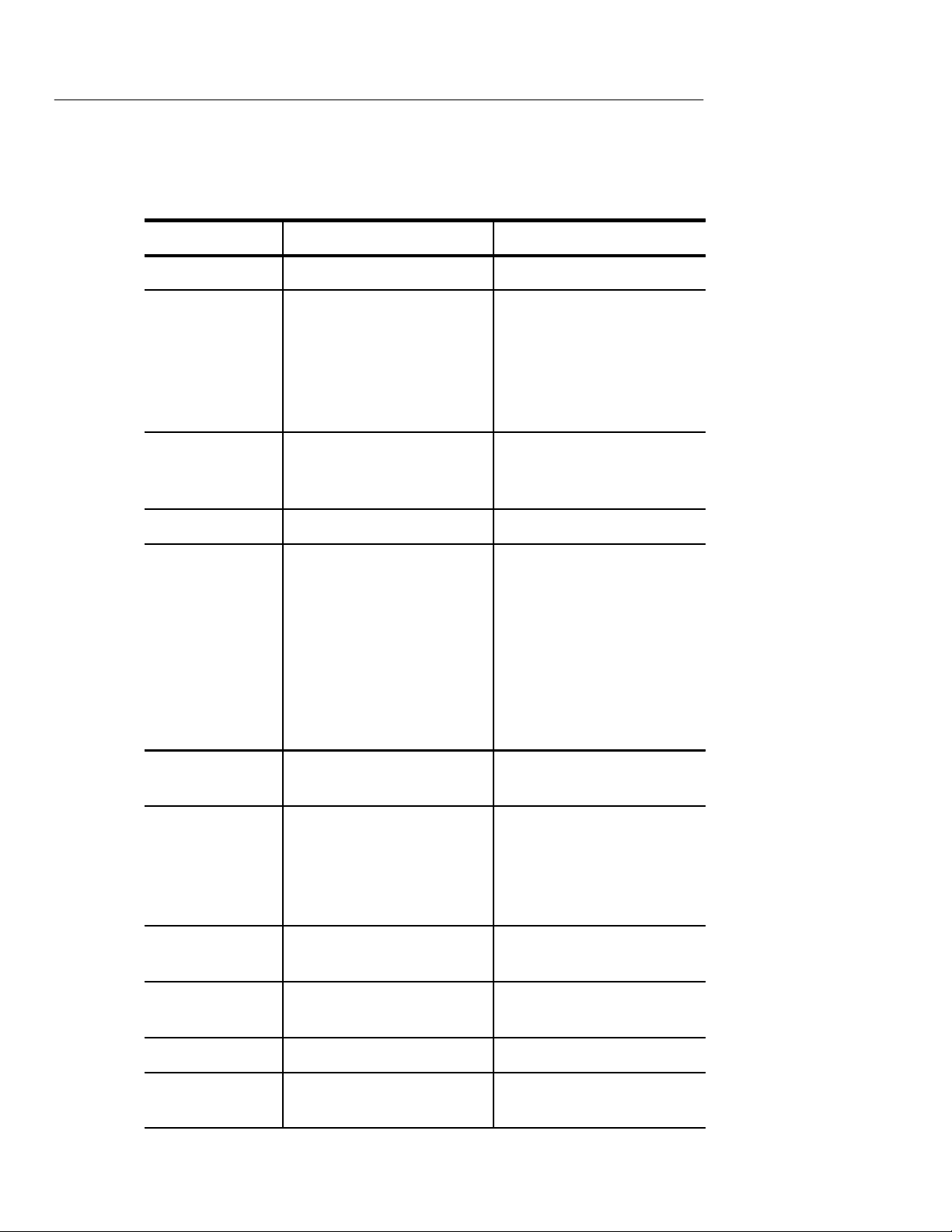
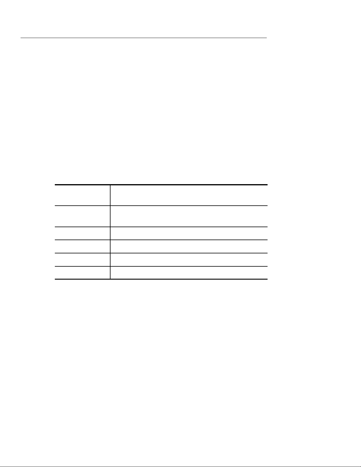
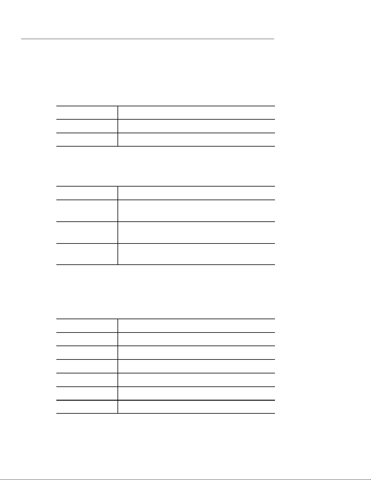
Printing Specifications
Characteristic Performance Required Supplemental Infor.
Writing method Direct thermal
Chart paper Roll type, 50mm. Outside
dia. 50mm max. Accept
15mm spindle. Thermal
coating facing inside roll.
Will allow recorder to meet
print density spec.
End-of-roll warning
Print color Black
Print density Solid black print pattern
Shall be marked by a red
line beginning 5 ft. from the
end of the roll.
shall measure at 1.1D on
Kodak Gray Scale.
Example: See Tektronix
part number in Accessories
section.
Pattern created by printing
40 element blocks three
times each until a 360 bit
wide by at least 200 bit long
(45mm by 25mm min.)
image is formed. Density
measurement made with an
appropriate Densitometer.
Patten print at 25°C ± 5°C.
2–2
Background density
Print drop-outs No more than 1% of the
Print element
width
Addressable print
elements
Print field width 48mm
Alignment of print
field
Less than 0.2 D when
stored at 70°C for 24 hours.
elements to be printed shall
fail to print. Adjacent failures shall number three or
less.
0.125mm
384 (48 8-bit bytes)
Entire print field must lie on
paper.
YT-1 / YT-1S Chart Recorder
Page 19
General Information and Specifications
Characteristic Supplemental Infor.Performance Required
Orthogonality of
print field
Paper movement
per ADVANCE
command
Record length 10.87 to 12.76 inches Algo-
Print time Typical 20 seconds Algo-
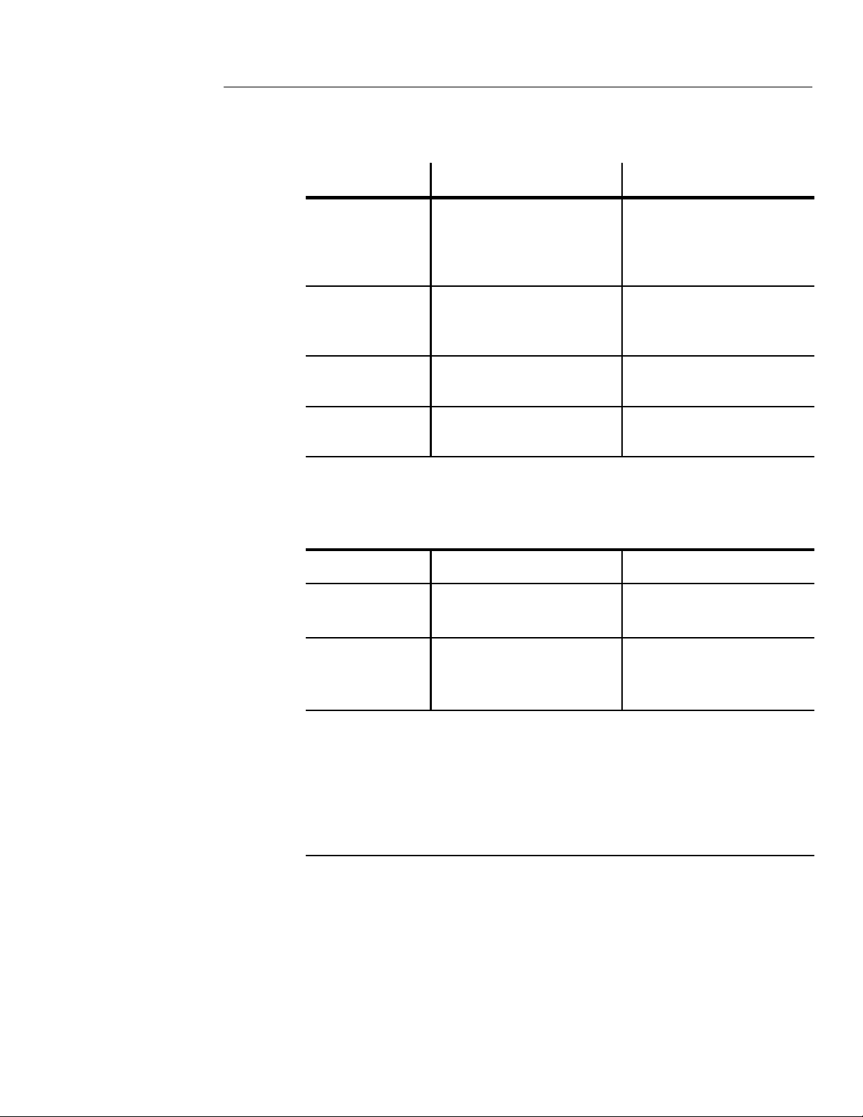
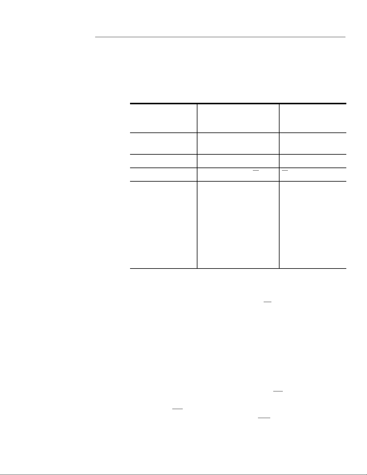
Power Specifications
A line printed across the
paper shall be perpendicular to the edge of the paper
within 1.0 degrees.
0.125mm, ± 0.01mm
rithm dependent
rithm dependent.
Characteristic Performance Required Supplemental Infor.
+5 Volts +5V ± 5%, 500mW max Power is applied to recorder
only while it is operating.
+16 Volts +16 Volts ± 10%. Average
Power = 12W max. Peak
current not to exceed 1.7A.
Mechanical Characteristics: YT-1/YT-1S plugs into the parent
instrument Option Port.
YT-1 / YT-1S Chart Recorder
2–3
Page 20

General Information and Specifications
Environmental Specifications: Apply when chart recorder is properly
installed in a 1500B/C-series TDR Option Port.
Temperature:
Operating
Non-operating
Humidity:
Operating
Non-operating
Altitude
Operating
Non-operating
Vibration 5 to 15Hz, 0.7g
Shock 30g, 11ms 1/2 sine wave-
–10°C to +55°C
–62°C to +85°C
0 to 100% RH, excluding
condensing
0 to 100% RH, including
condensation
To 15,000 ft above sea level
To 40,000 ft above sea level
MIL-T-28800C
15 to 25Hz, 1.3g
25 to 55Hz, 3.0g
form three shocks in each
direction on each axis.
Prolonged exposure to
temperatures above 70°C
might cause thermal paper
to darken.
Shock or vibration greater
than1g may cause temporary trace discontinuity.
Salt atmosphere 48 hours, 20% solution. Per
MIL-T-28800C.
Electromagnetic
compatibility
Electrostatic discharge
Water resistance Splash-proof and drip-proof
When operated in host
instrument, unit meets the
following requirements of
MIL-STD-461A: CE02,
CE04, CS02, CS06, RE02,
RE02.1, RS03, RS03.1.
3kV to 20kV, Tekronix standard 062–2862–XX
2–4
YT-1 / YT-1S Chart Recorder
Page 21

Operator Performance Checks
Page 22

Page 23
Operator Performance Checks
The following checks will confirm if the YT-1/YT-1S is operating
according to specification. They are found in the Chart Diagnostics
Menu in the Diagnostics Menu of the parent instrument.
Head Alignment Chart Diagnostic
This test gives the chart recorder a rapid feed test as well as a test for
print dropouts, feed spacing, and alignment of the head. If the
YT-1/YT-1S is not operating properly, symptoms may include pixel
drop-out, washed-out print, ‘‘titled’’ chart, chart off the page, or
improper or erratic speed.
Chart Quality
1. Access the Head Alignment chart in the Chart Diagnostics menu
located under the Diagnostics Menu of the parent instrument.
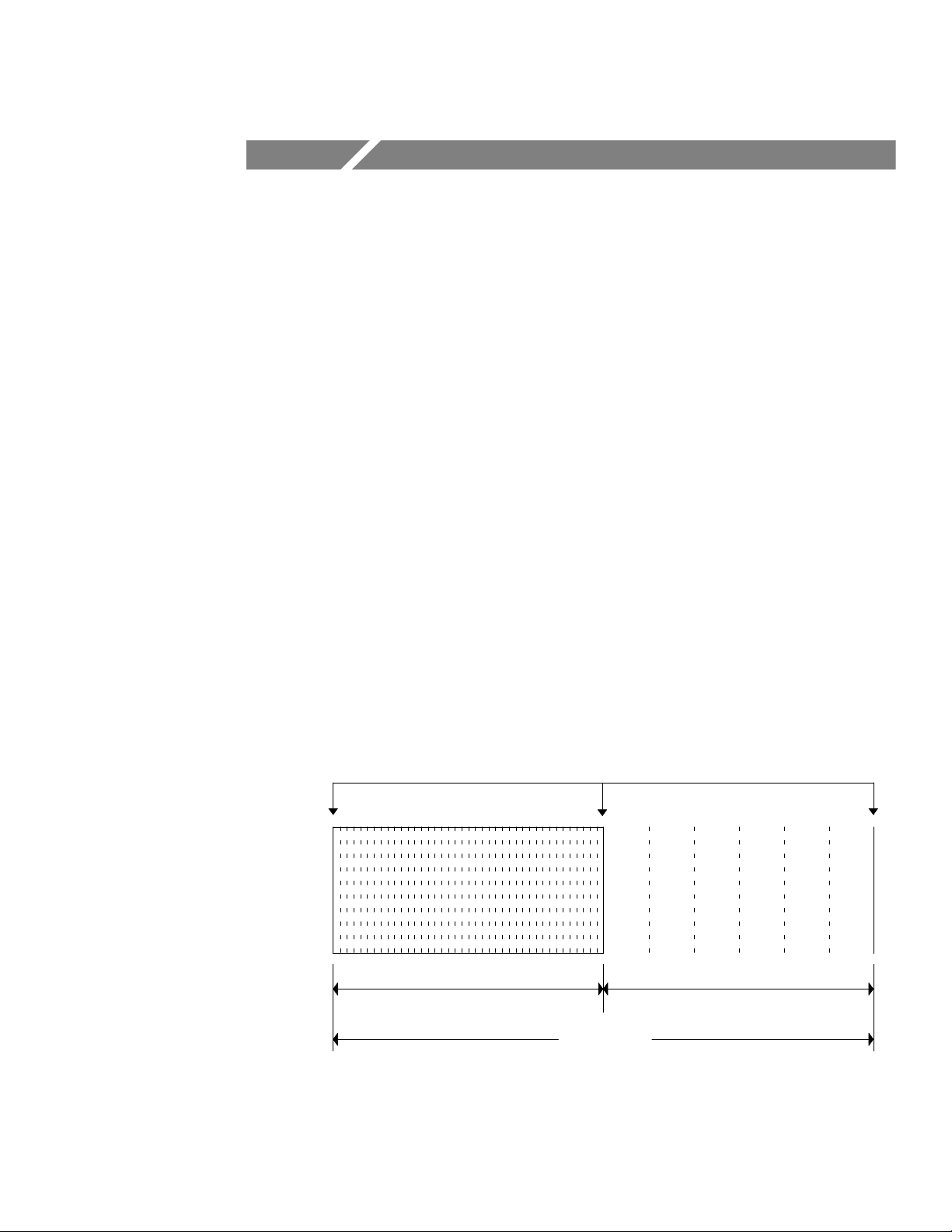
2. Press MENU. The diagnostic chart that is printed should look like
the figure below and must meet the following criteria:
SOLID LINES
Equally Spaced Wide LinesEqually Spaced Narrow Lines
6 Inches 6 Inches
12 INCHES
a. The total chart from first printed line to last printed line
must measure between 10.87 to 12.76 inches.
YT-1 / YT-1S Chart Recorder
3–1
Page 24

Operator Performance Checks
b. There must be between 5.43 to 6.38 inches of narrow
spaced lines on the chart.
c. There must be between 5.43 to 6.38 inches of wide spaced
lines on the chart.
d. Fold the paper in half at the last narrow line. The two
halves of the chart should be equal in length.
e. The entire diagnostic should be printed within the
boundaries of the paper .
f. All vertical lines should be perpendicular relative to the
top and bottom of the chart within 1°.
g. The three solid vertical lines on the chart must be
complete with no missing dots.
h. All lines on the chart must be legible with no fading,
smearing, or irregularities in print blackness.
If your test chart does not meet the above criteria, send your chart
recorder and include the test chart.
3–2
YT-1 / YT-1S Chart Recorder
Page 25

Accessories and Options
Page 26

Page 27
Accessories and Options
Standard Accessories
Accessory Tektronix Part Number
Chart paper, single roll 006–7647–00
Optional Accessories
Accessory Tektronix Part Number
Chart paper, 25–roll quantity 006–7677–00
Chart paper, 100–roll quantity 006–7681–00
Options
There are no options for the YT-1/YT-1S Chart Recorder
YT-1 / YT-1S Chart Recorder
4–1
Page 28

Accessories and Options
4–2
YT-1 / YT-1S Chart Recorder
Page 29

W ARNING
The following servicing instructions are for use only by
qualified personnel. To avoid injury, do not perform any
servicing other than that stated in the operating instructions
unless you are qualified to do so. Refer to all safety
summaries before performing any service.
Page 30

Page 31

Theory of Operations
Page 32

Page 33

Theory of Operations
Introduction
The YT-1/YT-1S Chart Recorder is to be used with a parent
instrument, such as the 1502B/C or 1503B/C Time Domain
Reflectometer. This manual contains information on the YT-1/YT -1S
only. For related information on the parent instrument, see Option
Port Interface in the Circuit Description section of respective service
manual.
The YT-1/YT-1S consists of a drive motor assembly, a thermal
printhead, and an electronic circuit board.
More information can be found in the Specification section of this
manual. A block diagram of the Option Port can be found in the
parent manual in the Circuit Description section. See the following
figure for the block diagram of the YT-1/YT-1S Chart Recorder.
Controller Board
To
Option
Port
J1
6
Power
and
Ground
6
8
1
Interrupt
Switch
Address
and
Control
Data
Motor Assembly
Motor
Control
1
3
Decode
and
Control
1
Data
Latch
4
Status
3
2
1
1
Serial Word
Load
1
Power and
2
Ground
J3
4
1
7
J2
Drive Motor
Control
Printhead
Thermal Print
Assembly
Thermal
Printhead
YT-1 / YT-1S Chart Recorder
5–1
Page 34

Theory of Operations
Circuit Description
BitĆMap (Data Matrix) Operation
Bit-Map Description
Bit–map operation permits the host to control the 384 individual bits
(48 bytes) that make up the recorder print field. This allows any
combination of dots to be printed including alpha-numerical
characters and graphics. All print data should be sent in the form of
bytes (1 byte = 8 bits). The state of the dots printed is controlled by
the state of the data bits sent by the host to the recorder. A ‘‘0’’ will
turn an element off and a ‘‘1’’ will turn an element on when a row is
printed. The bit-mapping is done on rows of the page. There are 8
rows per millimeter and 48 bytes per row. The resolution is thus
1/8mm across the page.
Bit-Map Operation
The recorder uses a thermal printhead with 384 individual elements
(48 bytes). The bytes of digital data are shifted through the printhead
from left to right. As the new bytes of data are shifted in by the host,
the old bytes remaining from the previous line of print data are
shifted out one by one. To replace all the old data bytes with new
ones the host must completely refill the printhead each time a new
line is to be printed. If the host does not completely refill the
printhead with a new line of data before printing, the remaining old
data will be printed out with the new data. The new data will also be
shifted to the left of its proper print field.
The host should never attempt to turn on more than 25% of the dots
in the print field at one time. If the host’s desired pattern requires the
energizing of more that 25% of the dots on a single line, the solution
is to divide the pattern into smaller parts. These smaller parts can
then be loaded and printed one at a time until the complete pattern is
printed. The host can then move on to the next line of print data by
advancing the paper . Bits will be turned on as shown:
5–2
YT-1 / YT-1S Chart Recorder
Page 35
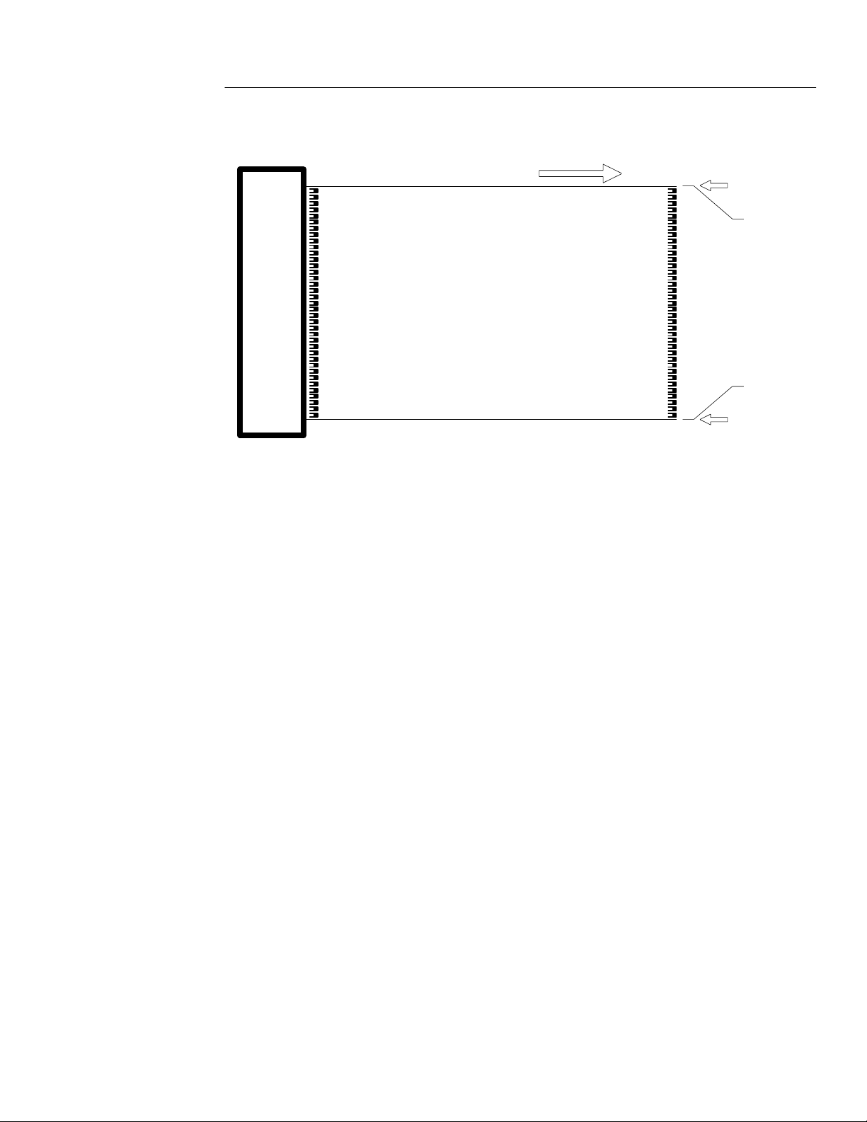
Theory of Operations
Direction of Paper Travel
Thermal Paper
Thermal
Printhead
Printed side of paper
Individual Write Command Operation
Load a Byte of Print Data
BYTE 1 on
this side
48 bytes wide
Host usable print field
BYTE 48 on
this side
When this write command operation is used the recorder will take
the data byte (8 bits) that the host has placed on the data bus and
shift it out to the recorder printhead. This command should only be
used when the recorder is ready to accept data (i.e. the Accept Data
status line D5 = 1). Use of this command will cause the Accept Data
status line to be disabled (D5 = 0). This status line will not be
re-enabled until the recorder is ready to accept another data byte. No
byte should be sent until this line goes high again (D5 = 1).
Latch a Line of Print Data
This write command operation should precede the print command.
When the host has completely finished loading the printhead with
data this command is used to latch that data into the printhead so that
it can be printed. This command should only be used when the
recorder is not printing or shifting data (i.e., both Print Ready and
Accept Data status lines are high D6 = 1, D5 = 1). Sending this
command while either of these status line is disabled could cause
faulty data to be printed out.
YT-1 / YT-1S Chart Recorder
5–3
Page 36

Theory of Operations
Print a Line of Data
This write operation causes the line of print data that the host has
loaded and latched into the printhead to be printed. This command
should only be used when the recorder is ready to print (i.e., the Print
Ready status line D6 = 1). This host should never attempt to turn on
more that 25% of the dots in the print field at one time. If the host’s
desired pattern requires the energizing of more than 25% of the dots
on a single line, the solution is to divide the pattern into smaller
parts. These smaller parts can then be loaded and printed one at a
time until the complete pattern is printed. The host can then move on
to the next line to print data by advancing the paper.
Advance Paper One Line
This write command operation causes the recorder to advance the
paper one line (1/8mm). This command can be used after printing to
move to the next print line or can be used without having printed to
create a blank line or print leader. This command should only be
used when the recorder is ready to advance (i.e., the Advance Ready
status line D4 = 1). Sending this command while the status line is
disabled will disrupt the recorder’s stepper motor and cause erratic
motor action to result.
5–4
Print a Line and Advance Paper One Line
This write command operation combines the print and advance
commands previously discussed. Upon receiving this command the
recorder will print the current line of print data and advance the
paper to the next line. This command should only be used when the
recorder is not printing or advancing the paper (i.e., both Print Ready
and Advance Ready status lines are high D6 = 1, D4 = 1). Sending
this command before the recorder is ready could cause printing errors
or erratic motor action.
Reset Recorder to Quiescent State
This write command resets the recorder to a quiescent state waiting
for the host to send a command. After reset the host should still
check the status lines before sending a command to insure the
recorder is ready.
YT-1 / YT-1S Chart Recorder
Page 37

Individual Read Command Operation
Read Recorder Identify Code
This read command operation allows the host to identify the recorder
and insure that it is properly inserted into the host unit. The recorder
has an identify code of (01H).
Read Recorder Status Codes
This read command operation allows the host to insure that the
recorder is ready to accept the desired command. The host must
always wait until the recorder is ready before sending a command.
By checking the corresponding status line or lines the host can
determine recorder readiness. There are status lines for Ready to
Print (D6), Ready to Advance (D4), Ready to Accept Data (D5), and
Recorder Fault (D7). Only send commands when the recorder is
ready.
Theory of Operations
Protocol
Introduction
This protocol is designed for the Tektronix YT-1/YT -1S bit map only
thermal dot matrix recorder.
The Tektronix YT-1/YT -1S chart recorder produces a hard copy
record on thermally activated paper of data provided through a
parallel digital interface. The bit map (dot matrix) data is provided
one byte at a time (1 byte = 8 bits) line by line (1 print line = 48
bits). This allows any combination of dots to be printed including
alpha-numeric characters and graphics. Each dot corresponds to one
element of a thermal printhead with a resolution of 200 dots per inch
(8 dots per mm). Printing is achieved by energizing the individual
elements of the printhead.
YT-1 / YT-1S Chart Recorder
5–5
Page 38
Theory of Operations
Interface Information
The YT-1/YT-1S chart recorder communicates to the host system via
the host’ s address and data bus. The interface includes four address
lines, eight data lines, one interrupt line, and three control lines. All
interface lines are 74HC compatible.
Inputs and Outputs
The following signal descriptions apply to the host-to-recorder
interface. Refer to the following table for pin designations (see
Interface Pin Structure).
A0 – A3 (INPUT): Address lines from the host for the read and write
operations to the recorder (all lines active high).
D0 – D7 (INPUT): Bidirectional data lines for the read and write operations
to the recorder (all lines active high).
(INPUT): Recorder select line from the host (active low).
(INPUT): Data read line from the host (active low).
(INPUT): Data write line from the host (active low).
(OUTPUT): Interrupt request line from the recorder (active low).
Interface Pin Structure
The interface pin structure table along with the associated waveforms
are in the Maintenance section of this manual. A 25-pin male D-shell
connector is used on the recorder . Information about the operation of
these pins is available under Option Port Interface in the Circuit
Description section of the 1502B and 1503B Service manuals.
5–6
YT-1 / YT-1S Chart Recorder
Page 39
Theory of Operations
Interface Characteristics
Characteristic Performance Required Supplemental Info
Connector 25-pin male D-shell (Holm-
berg HYM25A28AP or
equiv.)
Protocol As defined under heading:
Protocol
Logic Interface 74HC CMAS or equiv.
Print Initiation Ground Closure on IR IR = Pin 7
Command
Execution Times Print
Command
2.5ms typical. Measure from
time command sent to time
BUSY flag clears.
Advance
Load Data Byte
Latch Printhead Data
4ms typical
< 5µs typical
< 5µs typical
General Interrupt Operations
The recorder generates an interrupt request (IR
) each time the record
push button is depressed. This signal is active low. This signal does
not disable communication between the host and the recorder, thus
allowing read and write operations to continue even though an
interrupt request has been received.
General Command Operations
All commands are sent from the host to the recorder over the address
interface bus (A0 - A3). All commands are accompanied by a low
strobe of the recorder select line from the host (RS
). All read
commands are accompanied by a low strobe of the data read line
from the host (RD
strobe at the date write line from the host (WR
). All write commands are accompanied by a low
).
YT-1 / YT-1S Chart Recorder
5–7
Page 40
Theory of Operations
Read Command Operations
The recorder has the following read command operations:
Address 0H Identify code for recorder (Recorder = 01H)
Address 1H Status codes for recorder
Address 2H – FH Not used by recorder
The status code bits are formatted as follows:
D0 – D3 Not used by recorder
D4 Indicates recorder ready to accept advance command;
0 = Recorder not ready
D6 1 Indicates recorder ready to accept print command;
0 = Recorder not ready
D7 0 Indicates recorder fault exists;
1 = No fault exists
Write Command Operations
The recorder has the following write command operations:
Address 0H Reset recorder to quiescent state
Address 1H Advance paper one line with no printing
Address 2H Load a byte of print data (8 bits)
Address 3H Latch a line of print data
Address 4H Print a line and advance the paper one line
Address 5H Print a line with no advance of paper
5–8
Address 6H – FH Not used by recorder
YT-1 / YT-1S Chart Recorder
Page 41

Calibration
Page 42

Page 43

Calibration
The YT-1/YT-1S Chart Recorder has no electrical adjustments, and
few mechanical adjustments. Since the mechanical adjustments are
done at the factory, they are not included in the Calibration section.
The mechanical adjustments can be found in the Maintenance
section. The Performance Check will determine whether or not the
instrument is operating according to published specifications.
The YT-1/YT-1S Chart Recorder Performance Check is accomplished via a diagnostic test on the parent instrument (1500B/C-series)
LCD Chart Diagnostic
Technically this is not a diagnostic, but for assistance in troubleshooting, temporary adjust of the printing characteristics, and a
back-up for the PRINT push button.
For information on the troubleshooting aspects of LCD Chart, see the
Maintenance section of this manual.
The printing characteristics of the YT-1/YT-1S are designed to
provide chart recordings in environmental extremes under varying
conditions. If it does become necessary to change the chart
characteristics, it is possible from the front panel of the 1500B/C-series instrument.
The thermal printhead of the YT-1/YT-1S has 384 print elements.
Because of power economy, not all of the elements are turned on at
the same time. When printing, only 40 elements (or dots) of the
printhead are activated at a time. Forty dots equals a segment. If it is
intended to make the dots darker, elements can be turned on more
than once, analogous to a ‘‘double-strike’’ on a mechanical printer.
1. Using MENU and POSITION, access LCD chart in the Chart
Diagnostics menu.
YT-1 / YT-1S Chart Recorder
6–1
Page 44

Calibration
2. When adjusted, the left Vp knob will adjust the number of dots
the YT-1/YT-1S will print per segment, ranging from 13 to 41.
The effect of this adjustment is subtle.
3. When adjusted, the right Vp knob will adjust the number of prints
or ‘‘strikes’’ per segment. This adjustment is quite dramatic,
resulting in a much darker or lighter chart, and a corresponding
change in printer speed.
0.00 ft
auto
O
O
O
ac
F
F
F
F
F
F
When the parent instrument POWER is turned on, the printing
characteristics will default to 40 elements per segment and one print
per segment.
6–2
YT-1 / YT-1S Chart Recorder
Page 45

Calibration
This diagnostic also takes the place of the PRINT push button. If the
button should become defective, simply run the LCD chart
diagnostic and current screen will be printed.
Paper Skew
If the paper tends to run up to the top or down to the bottom of the
paper exit slot of the recorder, the paper skew may need adjustment.
Symptoms include information printed off the top or bottom of the
page and paper jamming.
Occasionally the paper may skew after the paper has been replaced.
This is due to improper setting of the paper in the feed path. This
will usually clear itself after a couple of charts. If it does not, the
paper still skews after a minimum of two charts, the paper guide
would be adjusted.
If the YT-1/YT-1S did not pass the Head Alignment Chart diagnostic,
refer to the Maintenance section of this manual.
Performance Check
The following checks will confirm if the YT-1/YT-1S is operating
according to specification. They are found under ‘‘Chart Diagnostics
Menu’’ in the ‘‘Diagnostics Menu’’.
Head Alignment Chart Diagnostic
This test gives the chart recorder a rapid feed test as well as a test for
print dropouts, feed spacing, and alignment of the head. If the
YT-1/YT-1S is not operating properly, symptoms may include pixel
drop-out, washed-out print, ‘‘tilted’’ chart, chart off the page, or
improper or erratic speed.
Chart Quality
1. Access Head Alignment chart in the Chart Diagnostics menu
located under Diagnostics Menu of the parent instrument.
2. Press MENU. The diagnostic chart that is printed must meet these
criteria:
YT-1 / YT-1S Chart Recorder
6–3
Page 46

Calibration
a. The total chart from first printed line to last printed line
must measure between 10.87 to 12.76 inches.
b. There must be between 5.43 to 6.38 inches of narrow
spaced lines on the chart.
c. There must be between 5.43 to 6.38 inches of wide spaced
lines on the chart.
d. Fold the paper in half at the last narrow line. The two
halves of the chart should be equal in length.
e. The entire diagnostic should be printed within the
boundaries of the paper .
f. All vertical lines should be perpendicular relative to the
top and bottom of the chart within 1 degree.
g. The three solid vertical lines on the chart must be
complete with no missing dots.
h. All lines on the chart must be legible with no fading,
smearing, or irregularities in print blackness.
SOLID LINES
Equally Spaced Wide LinesEqually Spaced Narrow Lines
6 Inches 6 Inches
12 INCHES
6–4
YT-1 / YT-1S Chart Recorder
Page 47

Maintenance
Page 48

Page 49
Maintenance
This section contains information of preventive and corrective
maintenance, troubleshooting, and shipping instructions.
CAUTION. We recommend that service be performed at an authorized
Tektronix Service Center, or by a technician skilled in digital
sampling techniques. The cir cuit board has SMT devices that require
special equipment to replace. If found defective, we recommend that
the ECB be replaced as an entire unit. We have included a majorparts/connectors locator as an aid to assist in troubleshooting.
Required Tools
This is a list of common tools needed to accomplish the maintenance
procedures that follow.
Oscilloscope (Tektronix 5440 or equivalent)
Option Port extension cable (174–0950–00)
3/8 inch hex nutdriver
1/2 inch hex nutdriver
0.050 hex wrench
Phillips head screwdriver
Straight blade screwdriver
Long-nosed pliers
Cotton swabs
Preventive Maintenance
Preventive maintenance includes cleaning and visual inspection. A
convenient time to perform preventive maintenance is during the
periodic performance check/calibration procedure. If the instrument
has been subjected to extreme environments or harsh handling, more
frequent preventive maintenance may be necessary.
YT-1 / YT-1S Chart Recorder
7–1
Page 50

Maintenance
Cleaning
CAUTION. Do not use chemical cleaning agents that contain benzene,
toluene, xylene, acetone, etc., because of possible damage to plastics
in the instrument.
The outside chassis and front panel should be cleaned gently with a
damp cloth.
The interior of the YT-1/YT-1S is protected from dirt and dust as
long as it is installed in the option port and the print door is closed.
However, if interior cleaning is necessary, blow off accumulated dust
with low-pressure air, and remove remaining dirt with a soft brush,
cotton swab or pipe cleaner moistened with isopropyl alcohol. The
paper must be removed before cleaning with alcohol.
The thermal printhead can be cleaned with a soft cotton swab dipped
in a little alcohol. Latch the motor assembly out of the way, remove
the paper, and carefully clean the printhead by swabbing the surface.
Any of the surfaces that are in the paper path should also be cleaned.
Lubrication
No lubrication is necessary. It is recommended, however, that the
YT-1/YT-1S be cleaned on a regular basis.
Visual Inspection
Obvious defects such as broken connectors, damaged board, frayed
cables, improperly seated components and heat-damaged components should be corrected first before attempting further troubleshooting. Heat damage usually indicates a deeper problem
somewhere in the circuitry, and should be traced and corrected
immediately.
We do not recommend electrical checks of individual components
because defective components will become evident during
instrument operation.
7–2
YT-1 / YT-1S Chart Recorder
Page 51
Re-calibration
After maintenance has been performed, the instrument should be
checked per procedures explained in the Calibration section of this
manual.
Parts Removal/Replacement
The YT-1/YT-1S can be disassembled by following these directions
in order. It can be assembled by reversing the order.
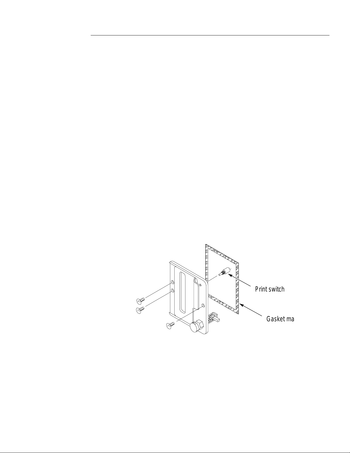
Front Panel Plate
1. Remove the three mounting screws (one on the right side of the
panel and two on the left) which secure the front panel to the
frame.
Maintenance
2. Remove the Print switch from the upper right corner of the front
panel (use care to not pull the wires loose from this switch).
Print switch
Gasket material
3. Inspect gasket material and replace if necessary (use Dow
Corning 3140 or equivalent to coat mating surface of gasket).
Paper Retaining Mandrel
4. Remove the two mounting screws on the right side panel that
attach the paper retaining mandrel assembly.
YT-1 / YT-1S Chart Recorder
7–3
Page 52

Maintenance
5. Remove the mandrel from the recorder .
Chart Drive Motor Assembly
6. Remove the two compression springs between the forward
support strut and motor drive assembly.
Drive
Motor
Springs
Compression
7. Remove the two mounting screws that hold the motor drive
assembly to the right side panel. They are located near the middle
of the right side panel.
7–4
YT-1 / YT-1S Chart Recorder
Page 53

Maintenance
8. With a long-nosed plier or screwdriver, remove the wire harness
connector from the ECB socket. Avoid scratching the printhead.
9. Remove the motor assembly through the top of the case.
Thermal Printhead
10.Remove the four mounting screws that attach the thermal
printhead to the left side panel.
Printhead
11. Carefully disconnect the thermal printhead from the ECB. Use an
IC puller or a long-nosed plier.
Controller Board
12.Remove three ECB mounting screws, washers and standoffs.
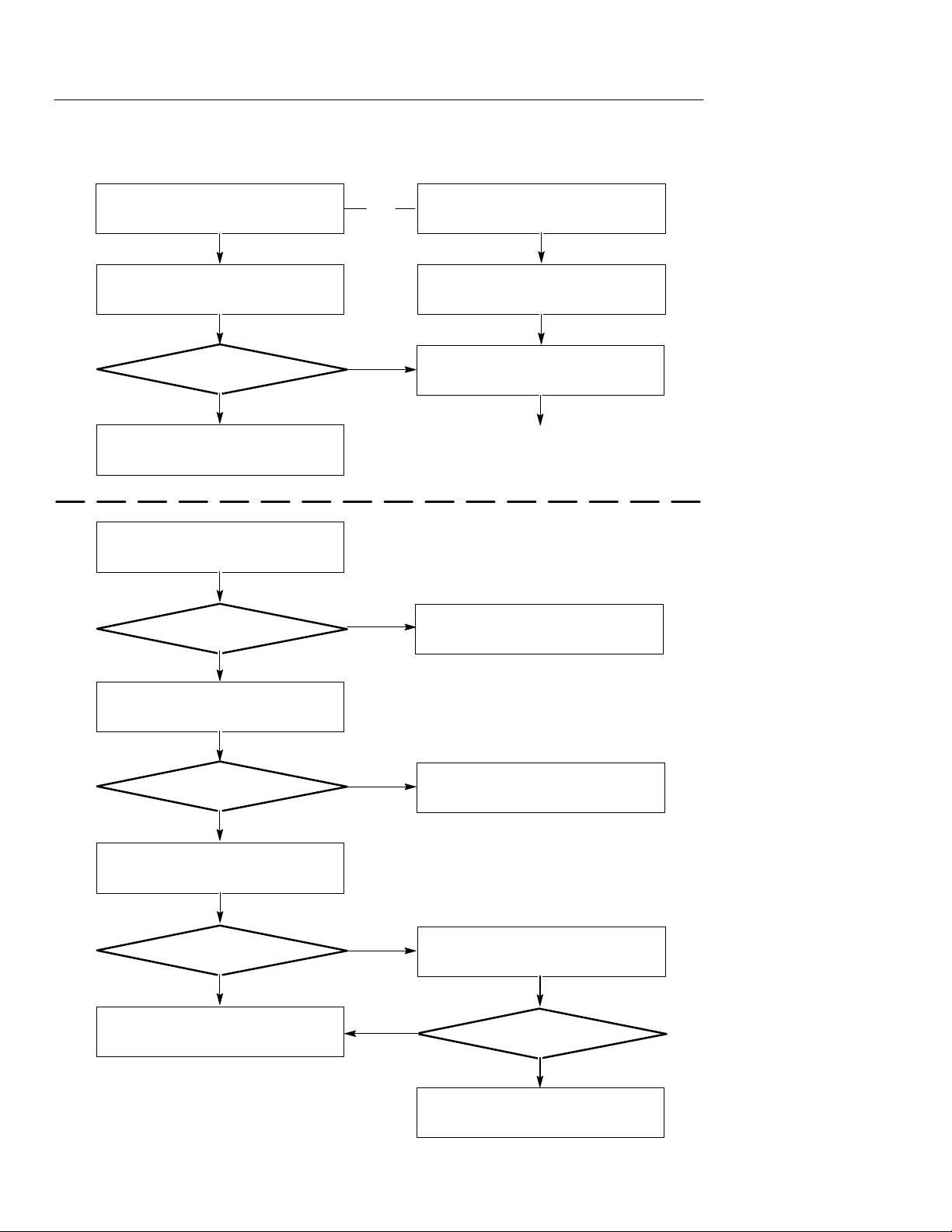
T roubleshooting
Troubleshooting Flow Charts
The following charts are provided to aid you in troubleshooting
electrical and mechanical problems with the YT-1/YT-1S. Additional
information follows the flow charts.
Nut
Spacer
ECB
Case
Back
Case
Bottom
YT-1 / YT-1S Chart Recorder
7–5
Page 54
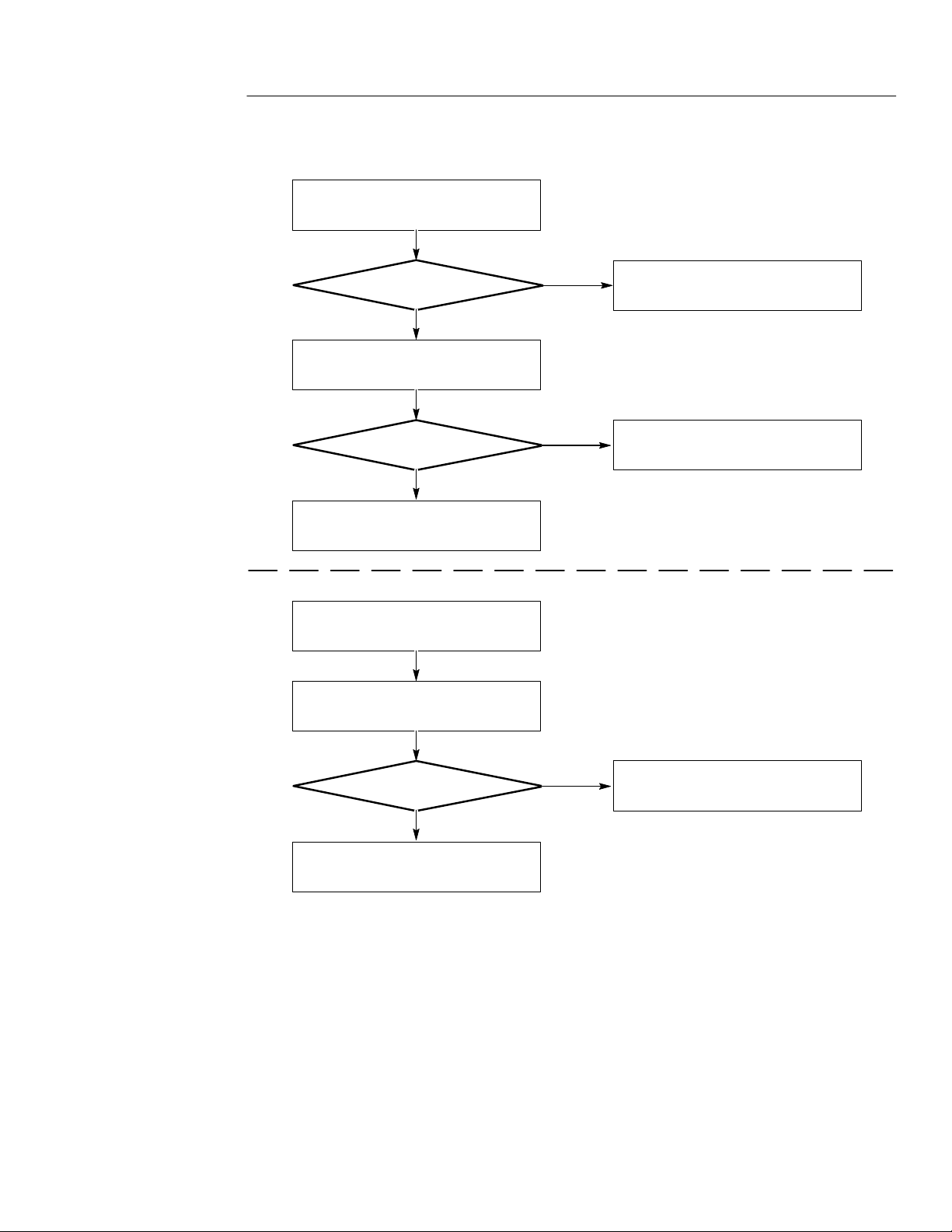
Maintenance
Paper skews up or down when printer is
operated
Run recorder at least four times to allow
the paper to realign
Is it correct now ?
NO
See the paper skew adjustment in
the maintenance section
Instrument shuts down when PRINT
button is pressed
Is unit running off of
battery?
OR
YES
YES
Print is not square with the paper
See the orthogonality adjustment in
the maintenance section
Unit functions
Be sure the battery is charged or
use AC power
NO
Unplug J2
Unit still shuts down when
PRINT is pressed
YES
Plug J2 back in and unplug J3
Unit still shuts down when
PRINT is pressed
YES
Run recorder at least four times to allow
the paper to realign
NO
NO
YES
Replace the print head assembly
Measure resistance between P3.1 & P3.2
and between P3.3 & P3.4
Is resistance approx 10 ohms
NO
Replace the motor assembly
7–6
YT-1 / YT-1S Chart Recorder
Page 55
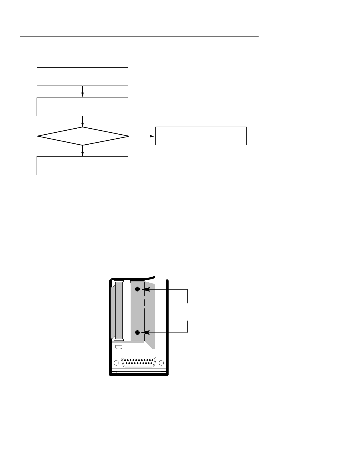
Motor advances but there is no print
Maintenance
Is the paper installed
correctly ?
YES
Check voltages and waveforms on
J2 on the ECB
Are they correct ?
YES
Replace the printhead assembly
The paper will not advance
Measure resistance between P3.1 & P3.2
and between P3.3 & P3.4
NO
Install the paper correctly
NO
Replace the ECB assembly
Is the resistance approx
10 ohms?
NO
Replace the motor assembly
YT-1 / YT-1S Chart Recorder
YES
Replace the ECB assembly
7–7
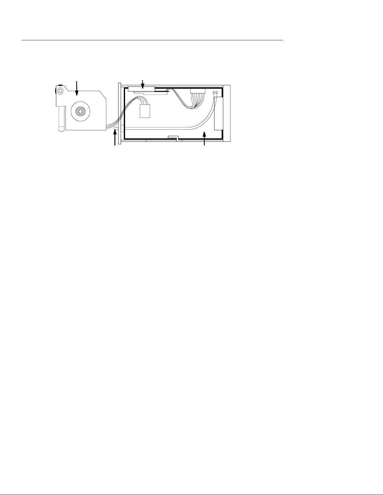
Page 56
Maintenance
Data garbled on the paper
Check voltages and waveforms on
Replace the printhead assembly
Mechanical
Paper Skew Adjustments
1. To adjust the paper guide, first remove the back panel, then the
paper and the paper retaining mandrel (see Part Removal/Replacement in this section).
J2 on the ECB
Are they correct ?
YES
NO
Replace the ECB assembly
7–8
Skew
Adjustment
2. The two screws holding the paper guide onto the motor assembly
must be loosened slightly (not too much!). Position the paper
guide as follows:
YT-1 / YT-1S Chart Recorder
Page 57

3. Paper Skews Downward
a. Move the top of the paper guide slightly away from the
printhead side of the instrument.
b. Tighten the two paper guide screws and replace the paper
retaining mandrel and the paper .
c. Run a minimum of two Print Head Alignment chart
diagnostics and check for proper paper tracking.
4. Paper Skews Upward
a. Move the top of the paper guide slightly closer from the
printhead side of the instrument.
b. Tighten the two paper guide screws and replace the paper
retaining mandrel and the paper .
Maintenance
If necessary, repeat the above procedure to fine tune the skew.
Electrical
ECB Inputs and Outputs
Accessing Connectors
To access J2 and J3, remove the ECB from the recorder. Disassemble
the chart recorder . Reconnect all wiring. Attach the Option Port
extension cable to the parent instrument’ s Option Port. Connect one
end of the cable to J2010 on the parent instrument Main Board and
the other end to J1 on the YT-1/YT-1S ECB.
c. Run a minimum of two Print Head Alignment chart
diagnostics and check for proper paper tracking.
YT-1 / YT-1S Chart Recorder
7–9
Page 58
Maintenance
Motor
Printhead
J2
J3
J1
Chart Recorder CCASwitch
The illustration above shows the connector locations in the
YT-1/YT-1S. Each connector and the signals that should be found on
them are described in the following paragraphs and tables.
J1 on ECB – Data and Voltage Input
The Option Port Diagnostic creates a repeating pattern of signals at
the option port connector to allow service technicians to verify that
all signals are present and working correctly. This test does not
generate any output to the LCD display.
There are two ways to terminate this diagnostic: hold down the
MENU button until the Option Port menu reappears, or momentarily
pull the line low.
The purpose of the diagnostic is to exercise the data and control lines
at the option port by creating a repeating pattern of signals that can
be easily observed with an oscilloscope. The pattern on all data lines
is the same and the pattern on the four address lines is also the same.
Although the exact patterns on the read, write and enable lines vary,
the repetition interval is the same for all patterns (about 15
microseconds). The active low trigger line (pin14 on the 25-pin ‘‘D’’
connector) is unused in the diagnostic. The function of the line can
be tested by momentarily grounding it to exit the diagnostic and
return to the Option Port menu.
7–10
YT-1 / YT-1S Chart Recorder
Page 59

Pin In/Out Designation Function (Status)
25
In/Out D2 Data Line 2 (active high)
24 In/Out D3 Data Line 3 (active high)
23 In/Out D4 Data Line 4 (active high)
22 In/Out D5 Data Line 5 (active high)
21 In/Out D6 Data Line 6 (active high)
20 In/Out D7 Data Line 7 (active high)
19 Input A0 Address Line 0 (active high)
18 Input A1 Address Line 1 (active high)
17 Input A2 Address Line 2 (active high)
16 Input A3 Address Line 3 (active high)
Maintenance
15 –––– Reserved Reserved for host
14 –––– Reserved Reserved for host
13 Input +16 V +16 VDC Power (motor/print)
12 Input +16 V +16 VDC Power (motor/print)
11 –––– 16 V Return 16 VDC Return (Power GND)
10 –––– 16 V Return 16 VDC Return (Power GND)
9 Input +5 V +5 VDC Power (Logic)
8 –––– 5 V Return 5 VDC Return (logic GND)
7 Output IR INTERRUPT REQUEST (active low)
6 Not used
YT-1 / YT-1S Chart Recorder
7–11
Page 60

Maintenance
J2 on ECB – Thermal Printhead Output
Pin In/Out Designation Function (Status)
5
Input RS RECORDER SELECT (active low)
4 Input RD DATA READ (active low)
3 Input WR DATA WRITE (active low)
2 In/Out D0 Data Line 0 (active high)
1 In/Out D1 Data Line 1 (active high)
J2, Pin No. Data Present
1 +5 VDC ± 0.5 V
2 +16 VDC ± 1.5 V
3 +16 VDC ± 1.5 V
4 +5 VDC ± 0.5 V
5 Ground
6 Ground
7 5 V 500Hz Square Wave
8 5 V 500Hz Square Wave
9 5 V Data Stream
10 5 V Data Stream
11 5 V Data Stream
12 No connection
13 +5 VDC ± 0.5 V
14 +5 VDC ± 0.5 V
7–12
YT-1 / YT-1S Chart Recorder
Page 61

J3 on ECB – Motor Drive Connector
J3, Pin No. Data Present
1 16 V Data Stream
2 16 V Data Stream
3 16 V Data Stream
4 16 V Data Stream
Shipping Instructions
If possible, reuse the original packaging materials. If this is not
possible, use a carton with inside dimensions of no less than six
inches for cushioning materials, or obtain a shipping carton from an
authorized Tektronix Service Center.
Maintenance
Shipping Carton Test Strength
Gross Weight (lb) Carton Test Strength (lb)
0 – 10 200
10 – 30 275
30 – 120 375
120 – 140 500
140 – 160 600
1. Surround the instrument with polyethylene sheeting to protect the
finish of the instrument.
2. Cushion the instrument on all sides by tightly packing dunnage or
urethane foam between carton and instrument, allowing three
inches on all sides.
3. Seal carton with shipping tape or industrial stapler .
YT-1 / YT-1S Chart Recorder
7–13
Page 62

Maintenance
7–14
YT-1 / YT-1S Chart Recorder
Page 63

Replaceable Parts
Page 64

Page 65

Replaceable Parts List
This section contains a list or replaceable modules in the
YT-1/YT-1S. Use this list to identify and order replacement parts.
Parts Ordering Information
Replacement parts information is available from your Tektronix
Service Center or representative. Parts can be ordered through your
local Tektronix field office.
Changes to Tektronix instruments are sometimes made to accommodate improved components as they become available, and to provide
benefit of the latest circuit improvements developed by our
engineers.
When ordering parts, include the following information:
H Part number
H Instrument type or model number
H Instrument serial number
H Instrument modification number (if applicable)
Module Replacement
The YT-1/YT-1S is serviced by replacing defective modules. There
are three options you should consider:
Module Exchange
In some cases you may exchange the defective module for a
re-manufactured module. Re-manufactured modules cost significantly less than new modules, and meet the same factory specifications.
For more information about the module exchange program, call
1-800-832-3814.
YT-1 / YT-1S Chart Recorder
8–1
Page 66

Replaceable Parts
Module Repair
You may ship the defective module to Tektronix for repair. We will
repair and return the same module to you.
New Modules
New modules can be purchased like other replacement parts.
Using the Replaceable Parts List
The tabular information in the parts list is arranged for easy use.
The parts list is indented to indicate item relationships. The
following is an example of the indentation system used in the Name
and Description column:
Assembly and/or component
. Detail part of assembly or component
.. Parts of detail part
Abbreviations conform to American Nation Standards Institute
(ANSI) standard.
Tektronix Part Number
Use the part number when ordering a replacement part from
Tektronix.
Serial/Model No.
These columns show the serial numbers of the first and last
instruments in which a part was used. No entry in these columns
indicates that the part is used in all instruments.
Name and Description
In the parts list, an item name is separated from its description by a
color (:). Because of space limitations, an item name by be
8–2
YT-1 / YT-1S Chart Recorder
Page 67

Replaceable Parts
incomplete. For more name identification, refer to the U.S. Federal
Cataloging Handbook H6–1.
Mfr. Code and Mfg. Part Number
These columns list the code number of the manufacturer of the part,
and the manufacturer’s part number for the part. Refer to the Cross
Index, Mfg. Code Number to Manufacturer for names and addresses
of manufacturers.
CROSS INDEX – MFR. CODE NUMBER TO MANUFACTURER
Mfr. Code Manufacturer Address City, State, Zip Code
54318 ASTRO-MED INC 600 EAST GREENWICH AVE WEST WARWICK RI 02983–5446
80009 TEKTRONIX 14150 SC KARL BRAUN DR BEAVERTON OR 97007–0001
REPLACEABLE ELECTRICAL ASSEMBLIES
Fig
Tektronix
No.
Part No.
A1 118–7614–02 CIRCUIT BD ASSY:CONTROLLER W/ HARNESS 54318 32001–001
A2 118–7616–01 PRINTHEAD ASSY:THERMAL 54318 30995–014
Serial No.
Effective Dscont
Name & Description Mfg.
Code
Mfr. Part
No.
YT-1 / YT-1S Chart Recorder
8–3
Page 68

Replaceable Parts
REPLACEABLE MECHANICAL ASSEMBLIES
Fig
Tektronix
No.
Part No.
1 118–7613–01 MOTOR:CHART DRIVE ASSY 54318 31310–000
2 118–8357–00 MANDREL PAPER:W/HARDWARE 54318 22976–010
3 118–7617–00 . KNOB:PAPER RETAINING 54318 12676–001
4 118–7623–00 PANEL,REAR:W/PINS 54318 22354–002
5 118–7622–03 FRAME,CASE: 54318 31268–20X
6 118–7633–00 (3) SPACER:NYLON 54318 10831–000
7 –––– –––– CKT BD ASSY:SEE A1 REPL
8 118–7620–00 WIRING HARNESS:PUSHBUTTON,RECORD 54318 12629–000
Serial No.
Effective Dscont
Name & Description Mfg.
Code
Mfr. Part No.
9 118–7621–01 PANEL,FRONT:W/LATCH YT-1 ONLY 54318 22764–000
200–3498–00 DOOR ASSY:YT -1S ONLY 54318 31927–000
10 118–7628–00 . LATCH,DOOR:YT-1/YT-1S 54318 22766–000
11 118–7624–02 . GASKET:YT-1/YT-1S 54318 22769–000
12 –––– –––– THERMAL PRINTHEAD ASSY:SEE A2 REPL
13 174–3241–00 CABLE ASSY:CHAR T RECORDER PRINT 54318 22745–952
14 118–7619–00 SPRING:COMPRESSION 54318 10475–001
15 118–7631–00 BLOCK:SPRING SUPPORT 54318 12541–001
16 214–4728–00 BELT,TIMING:1/8 INCH WIDE 54318 22110–048
8–4
YT-1 / YT-1S Chart Recorder
Page 69
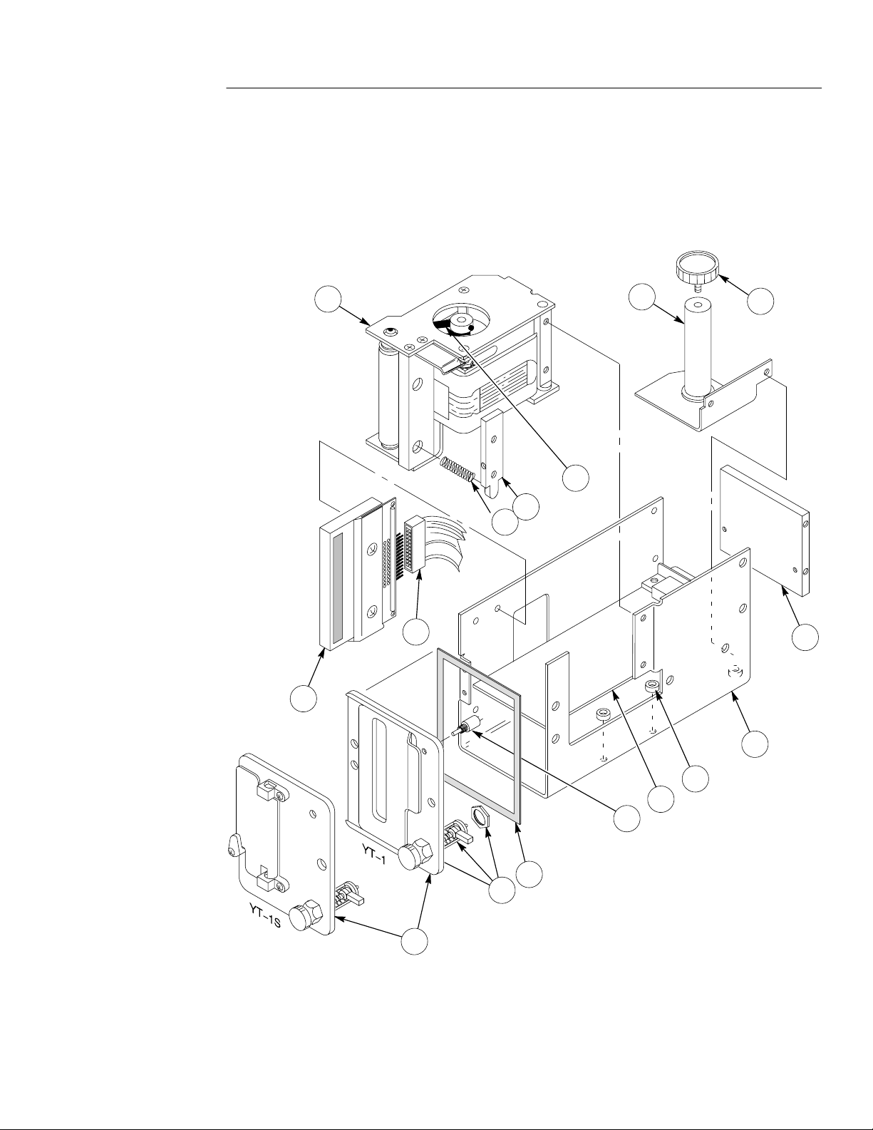
Replaceable Parts
A2
12
1
16
15
14
13
2
3
4
9
YT-1 / YT-1S Chart Recorder
10
11
5
6
7
8
A1
8–5
Page 70

Replaceable Parts
8–6
YT-1 / YT-1S Chart Recorder
Page 71

Page 72

 Loading...