

Page 1
Y-l
bnART
RE
INSTRUCTION
ORDER
MANUAL
Page 2
---
COMMITTED
TO
EXCELLENCE
Tektronix, Inc.
P.O.
Box
500
Beaverton,
OR
970TI
PLEASE CHECK
FOR
CHANGE
INFORMATION AT THE REAR
OF
THIS MANUAL.
Y-T
CHART
RECORDER
INSTRUCTION MANUAL
First Printing
Revised
OCT
NOV
1987
1984
Page 3
Copyright
O
1984, 1985, 1986,
and
1987
Tektronix, Inc. All
rights reserved. Contents of this publication .may not be repro-
duced in any form without the written permission of Tektronix,
Inc.
Products of Tektronix, Inc. and its subsidiaries are covered by
U.S.
and foreign patents andtor pending patents.
TEKTRONIX, TEK. and
are registered trademarks of
Tektronix, Inc. TELEQUIPMENT is a registered trademark of
U.K.
Tektronix.
Limited.
Printed in U.S.A. Specification and price change privileges are
reserved.
Page 4
REV
DEC
1986
TABLE
List of
Safety Summary
Section 1 INTRODUCTION AND SPECIFICATION
Section
Installation
Stylus Alignment
Chart Paper Alignment
Record
Evaluation
Battery Operating Time
Installing Chart Recorder Paper
illustrations
2
OPERATING INSTRUCTIONS
..........................................................................................
................................................................................................
..........................................................................................
..............................................................................
..........................................
................................................................................
OF CONTENTS
.
.......................................................................
..........................................
.........................................................
................................
............................
Page
iv
v
2-1
2-1
2-1
2-1
2-2
2-2
2-2
Page 5
Y-T
Chart Recorder
TABLE
3
Section
Motor Voltage Control
Heater Vottage Regulator
Pen Drive Amplifier
Speed Sensing 3-2
Section 4 CALIBRATION
Calibration for
Calibration for
CIRCUIT DESCRIPTION
1500
Stylus Temperature and Gain Adjustment
Chart Recorder Checks
Motor Speed Control Adjustment
OF
Stylus Temperature and Gain Adjustment
Motor Speed Adjustment
Chart Recorder Checks 4-8
Linearity Checks
OF
CONTENTS
(cont)
......................................................................
...................................................................
.........................................................................
...................................................................................
TDR Series
........................................................
......................................
..................................................................
....................................................
TDR Series
...........................................................
......................................
...............................................................
..................................................................
..........................................................................
Page
3-1
3-1
3-2
4-1
4-2
4-3
4-6
4-7
4-7
4-8
4-9
REV DEC
1986
Page 6
LE
OF CONTENTS
5
Section
Chart Recorder Repair
Changing the Stylus
Replacing the Rubber Rollers
Repacking for Shipment
Section 6 OPTIONS
Section
Section
Y-T
Section 9 REPLACEABLE MECHANICAL PARTS
Section
MAINTENANCE
.......................................................................
...........................................................................
............................................................
.....................................................................
7
REPLACEABLE ELECTRICAL PARTS
8
DIAGRAMS
Chart Recorder Schematic
10
ACCESSORIES
..........................................................
(cont)
Page
5-1
5-1
5-3
5-5
8-4
Y-T
Chart
Recorder
REV DEC 1986
iii
Page 7
Y-T
Chart
Recorder
TABLE OF ILLUSTRATIONS
Title
Tektronix Y-T Chart Recorder
Chart Recorder Controls
Stylus Position Adjusted
Chart Recorder Motor
Motor Speed Control
Verifying Peak-to-Peak Signals
Aligning Chart Paper
Location of Chart Recorder Components
Correct Alignment of Stylus Assembly Connecting Wire
Y-T Chart Recorder Circuit Board
Motor Speed Control Circuit Board
Modified Circuit Board
Y-T Chart Recorder Exploded View
Accessories 9-13
.................................................................................
.................................................................
..................................................................
...................................................................
.................................................................
.....................................................
..............................................................
..............................................................
..................................................
....................................
.............
...............................................
..............................................
............................................
Page
2-3
4-4
4-4
4-5
4-5
4-9
4-10
5-2
5-4
8-6
8-7
8-8
9-12
REV
JUN
1987
Page 8
Y-T
Chart
Recorder
ERATOR
The general safety information in this part of the sum-
mary is for both operating and servicing personnel. which could result in personal injury or loss of life.
Specific warnings and cautions will be found throughout
the manual where they apply, but may not appear in this
summary.
TERMS
In This
CAUTION
which could result in damage to the equipment or other
Property.
REV
Manual
statements identify conditions or practices
DEC
1986
SAF
WARNING
As
Marked
CAUTION
ately accessible as one reads the marking, or a hazard
to property including the equipment itself.
DANGER
accessible as one reads the marking.
statements identify conditions or practices
on
Equipment
indicates a personal injury hazard not irnrnedi-
indicates a personal injury hazard immediately
Page 9
Y-T
Chart Recorder
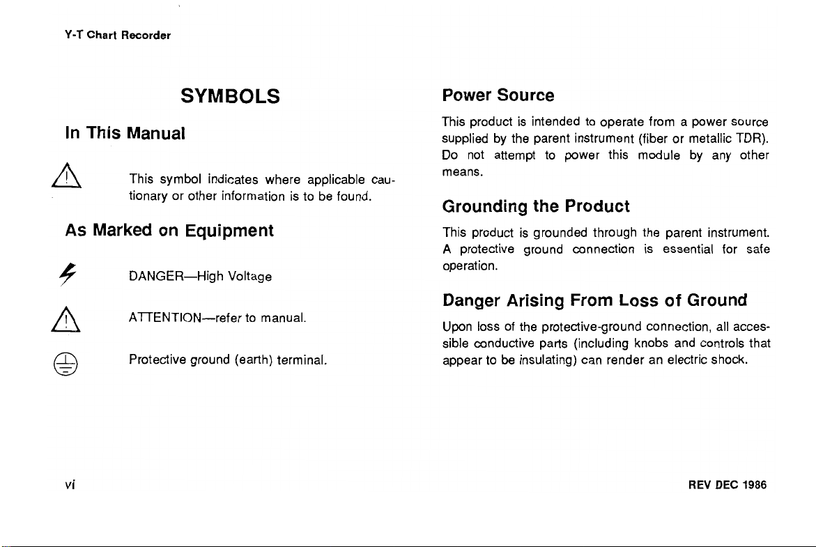
SYMBOLS
In
This
Manual
This symbol indicates where applicable cau-
tionary or other information is to be found.
As
Marked on Equipment
b
@
DANGER-High Voltage
AlTENTION-refer to manual.
Protective ground (earth) terminal.
Power Source
This product is intended to operate from a power source
supplied by the parent instrument (fiber or metallic TDR).
Do not attempt to power this module by any other
means.
Grounding the Product
This product is grounded through the parent instrument.
A
protective ground connection is essential for safe
operation.
Danger Arising From Loss
Upon loss of the protective-ground connection, all acces-
sible conductive parts (including knobs and controls that
appear to
be
insulating) can render an electric shock.
of
Ground
REV DEC
1986
Page 10
Y-T
Chart
Recorder
Do Not Operate in Explosive
Atmospheres
To avoid explosion, do not operate this product in an
it
explosive atmosphere unless
certified for such operation.
has been specifically
Do Not Service Alone
Do not perform internal service or adjustment of this pro-
duct unless another person capable of rendering first aid
and resuscitation is present.
REV
DEC
1986
Use Care When Servicing With Power
On
Dangerous voltages exist at several points in this pro-
duct. To avoid personal injury, do not touch exposed
connections and components while power is on.
Disconnect power before removing protective panels,
soldering, or replacing components.
Do Not Remove Covers or Panels
To avoid personal injury, do not remove the product cov-
ers or panels. Do not operate the product without the
covers and panels properly installed.
vii
Page 11
INTRODUCTION AND SPECIFICATION
INTRODUCTION
The Tektronix
sory for the Tektronix Metallic and Optical Fiber Time
Domain Reflectometers.
place of the Blank Module or the
The chart recorder uses a heated stylus, and
heat sensitive chart paper to reproduce the
A
chart recording is a permanent record. It can be of
great service in fault interpretation (e.g., a chart record-
ing of a faulty twisted pair can
good twisted pair).
REV
DEC
1986
Y-T
Chart Recorder is an optional acces-
It
plugs into the instrument in
XY1
Output Module.
CRT
be
compared to that of a
4
cm wide
display.
SPECIFICATION
Table
1-1
lists the electrical characteristics and features
that apply to the Tektronix Y-T Chart Recorder when it is
installed in the Tektronix
TDR Series instruments after a
The Performance Requirement column describes the lim-
its of the characteristic and the Supplemental Information
column describes features and typical values or informa-
tion that may be helpful.
1500
TDR Series or the OF
20
minute warm-up.
Page 12
Y-T
Introduction and Specification
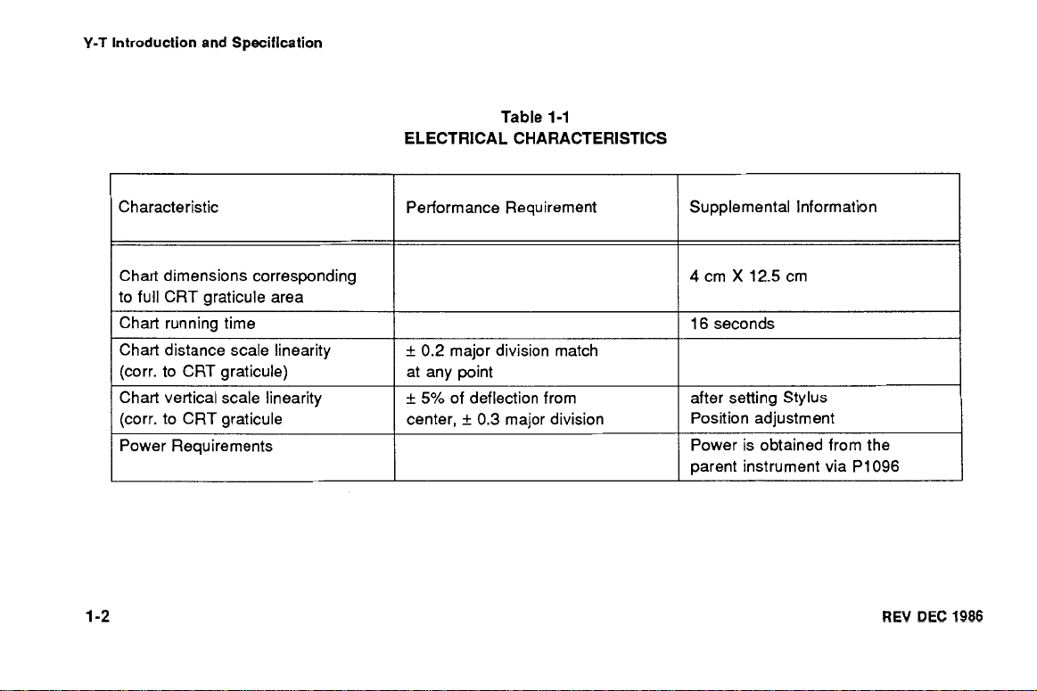
Table
1-1
ELECTRICAL CHARACTERISTICS
Characteristic Performance Requirement
Chart dimensions corresponding
to full CRT graticule area
Chart running time
Chart distance scale linearity
(corr. to CRT graticule)
Chart vertical scale linearity
(corr. to CRT graticule
Power Requirements
+
0.2 major division match
at any point
+
5%
of deflection from
+
0.3
center,
major division
Supplemental Information
16 seconds
after setting Stylus
Position adjustment
Power is obtained from the
parent instrument via P1096
REV
DEC
1986
Page 13
OPERATING INSTRUCTIONS
CAUTION
D
Turn the parent instrument's power switch
removing or installing the
Y-T
Chart Recorder.
Installation
The Tekronix Y-T Chart Recorder can be installed in the
instrument's plug-in module compartment. The LOCK
knob secures the chart recorder in the instrument.
Stylus Alignment
When the parent instrument's RECORD switch is
pressed, power is applied to the recorder stylus.
position of the stylus can then be aligned by adjusting
the STYLUS POSITION screw. Align the stylus to
correspond with the position of the CRT trace.
REV
DEC
1986
OFF
prior to
The
Chart Paper Alignment
To align the chart horizontally, pull the paper until a dark
line on the paper is aligned with the red reference line
visible through a sprocket hole.
Record
When the RECORD switch is pressed, then released, a
chart recording starts. The chart recording circuitry
automatically shuts off when the recording is completed.
Extra graph paper is run out to allow removal of the
recording. When removing the recording, tear paper
upward.
Page 14
Y-T
Operating Instructions
Evaluation
In evaluating a graph, the distance between two dark
horizontal lines corresponds to one vertical division of
the CRT display. The distance between two dark vertical
lines corresponds to one major horizontal division of the
CRT display.
Battery Operating Time
The chart recorder can make up to 20 graphs on a full
charge of the batteries; the instrument will still operate
for a minimum of 5 hours. After 20 graphs have been
made, the time that the instrument can be operated
without recharging the batteries will be reduced by
approximately three minutes per recording.
(1
500
Series)
Installing Chart Recorder Paper
Approximately 60 graphs can be made with one roll of
chart recorder paper for the 1500 TDR Series, or approx-
imately 120 for the OF
TDR
Series.
NOTE
Chart paper for the
is different. Check the Mechanical Parts List, Acces-
sories, section of this manual for the proper chart paper
part numbers.
Turn LOCK knob counter-clockwise and pull chart
recorder from the instrument.
Push in on the bottom edges of the bezel and lift
upward.
Remove empty spool from recorder by pulling it
upward.
Place new roll of graph paper in top of recorder
and push into place between the spring-loaded
paper holders. Be sure the grid of the paper faces
up (see Figure
1500
2-1).
TDR
and
OF
TDR
REV
instruments
DEC
1986
Page 15

Fig.
2-1.
Y-T
Chart
-pp
Recorder.
Y-T
Operating Instructions
Pull the paper over the rollers and down the front
of the recorder. Lower the bezel until it latches
into place.
Align the graph paper so that one of the dark lines
on the paper is lined
up
with the red reference line
visible through a sprocket hole. This sets the
graph paper
so
that a recording will start at one of
the dark lines corresponding to the edge of the
CRT graticule.
Place the chart recorder back into the instrument,
then turn the
LOCK
knob clockwise to lock.
REV
DEC
1986
Page 16
This section describes the Chart Recorder circuitry using
the circuit diagrams at the back of this manual. The
Chart Recorder contains three basic circuits: the motor
voltage control, heater voltage regulator, and a pen drive
amplifier.
Motor-Voltage Control
When pin 4 of P1096 is switched to 0
Q1015 is turned on and acts as a switch, which applies
12 volts to the Motor Speed Control.
Motor current and torque load are sensed by R2026 and
U2035A, providing a signal to U20358, where it is com-
pared with
circuit U20356 and transistors Q1039 and Q1 024 form
voltage-controlled current source for the drive motor.
REV
DEC
a
reference voltage set by R1015. Integrated
1986
V,
transistor
Heater-Voltage Regulator
This circuit provides 3 A at 1.0 V to the stylus heating
a
element. The circuit is
Transistor Q2023 acts as a series switch that supplies
current to energy storage device L1029. Transistors
Q4021 and Q3023 form the sensing amplifier whose sig-
nal is amplified by Q3028, (23027, Q3026, and Q4027 in
order to switch Q2023. Diode CR2031 shunts the
current that flows through L1029 when Q2023 is turned
off. Resistor R4017 is used to set the output voltage at
1
V.
The 1 V switching supply is controlled by the stylus
heat control line (pin 12), which is grounded when stylus
heat is required.
a
series-switching regulator type.
Page 17
Y-T
Circuit Description
Pen-Drive Amplifier
The pen-drive amplifier consists of operational amplifier
U3034
Q4033.
adjustment,
chart paper. Gain of the amplifier is controlled by
R2033,
amplifier circuit provides amplification to either positive or
negative going inputs. The
-8
trolled by the chart recorder power switches in the parent
instrument.
Diodes
drive amplifier from high reverse voltages which may
occur on the
Thermistor
motor non-linearity.
and power amplifiers
STYLUS
POSITION, an external screwdriver
R2034,
is used to center the stylus on the
Q4030, (24032, Q3033,
an internal screwdriver adjustment. The power
+5
V
and
-5 V (+8
V
for
1500
Series) to the power amplifiers are con-
CR4030
and
5
5
RT1039
CR4031
V
(5
and
are used to protect the pen
8 V 1500
R1037
Series) power bus.
compensate for pen
V
and
and
Speed Sensing
A speed-sensing circuit consists of
tosensitive transistor
Q0182
is activated by the passing of each sprocket hole.
The on-off rate of
Q0182.
Q01 82
is an indication of the paper
motor speed. This activation rate is used to synchronize
the display sweep speed with the proper paper motor
speed.
DS0282,
and pho-
As the paper travels,
REV
DEC 1986
Page 18
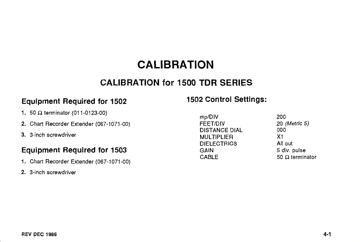
CALIBRATION
for
1500
TDR
SERIES
Equipment Required for 1502
l.
50 R terminator (01 1-0123-00)
2.
Chart Recorder Extender (067-1 071 -00)
3.
3-inch screwdriver
Equipment Required for 1503
1.
Chart Recorder Extender (067-1 071 -00)
2.
3-inch screwdriver
REV
DEC
1986
1502 Control Settings:
rnp1DIV 200
FEETtD
DISTANCE DIAL 000
MULTIPLIER
DIELECTRICS All out
GAIN
CABLE
IV 20 (Metric
X
1
5
div. pulse
R
terminator
50
5)
Page 19
Y-T
Calibration
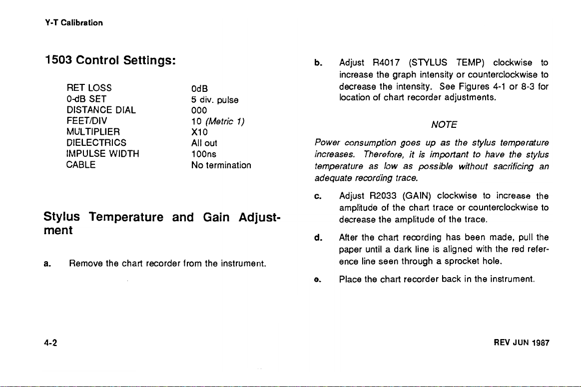
1503
Control Settings:
RET LOSS
OdB SET
DISTANCE DIAL
FEET/DIV
MULTIPLIER
DIELECTRICS
IMPULSE WIDTH
CABLE
Od
B
5
div. pulse
000
l0
(Metric
X1 0
All out
l
OOns
No termination
l)
Stylus Temperature and Gain Adjust-
ment
a.
Remove the chart recorder from the instrument.
b.
Adjust R4017 (STYLUS TEMP) clockwise to
increase the graph intensity or counterclockwise to
decrease the intensity. See Figures 4-1 or
location of chart recorder adjustments.
8-3
for
NOTE
Power consumption goes up as the stylus temperature
increases. Therefore, it is important to have the stylus
temperature as low as possible without sacrificing an
adequate remrding trace.
c.
Adjust R2033 (GAIN) clockwise to increase the
amplitude of the chart trace or counterclockwise to
decrease the amplitude of the trace.
After the chart recording has been made, pull the
d.
paper until a dark line is aligned with the red refer-
ence line seen through a sprocket hole.
Place the chart recorder back in the instrument.
e.
REV
JUN
1987
Page 20
Y-T
Calibration
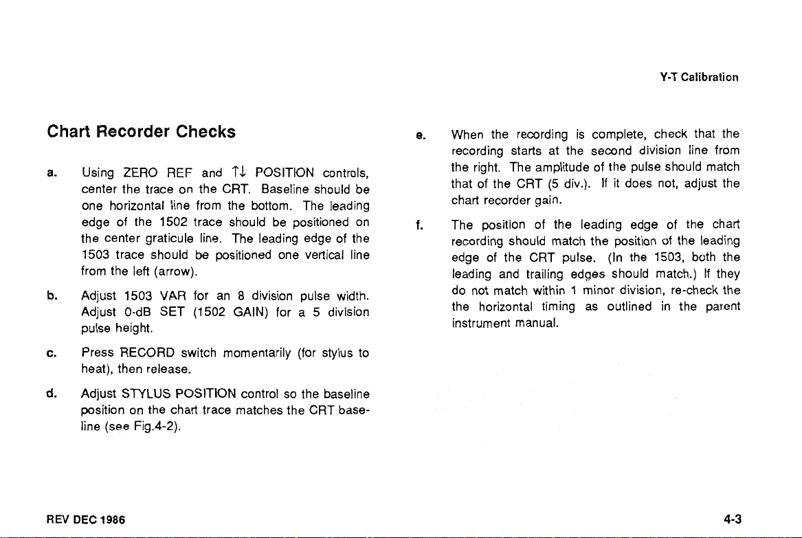
Chart Recorder Checks
Using
ZERO
center the trace on the CRT. Baseline should be
one horizontal line from the bottom. The !eading
edge of the 1502 trace should be positioned on
the center graticule line. The leading edge of the
1503 trace should
from the lefi (arrow).
Adjust 1503 VAR for an
Adjust 0-dB SET (1502 GAIN) for a
pulse height.
Press RECORD switch momentarily (for stylus to
heat), then release.
Adjust STYLUS POSITION control so the baseline
position on the chart trace matches the CRT base-
line (see
REV
DEC
1986
REF and POSITION controls,
be
positioned one vertical line
8
division pulse width.
Fig.4-2).
5
division
e.
When the recording is complete, check that the
recording starts at the second division line from
the right. The amplitude of the pulse should match
that of the CRT (5 div.). If it does not, adjust the
chart recorder gain.
The position of the leading edge of the chart
recording should match the position
of
edge of the CRT pulse. (In the 1503, both the
leading and trailing edges should match.)
1
do not match within
minor division, re-check the
the horizontal timing as outlined in the parent
instrilment manual.
the leading
If
they
Page 21
Calibration
Y-T
-
l
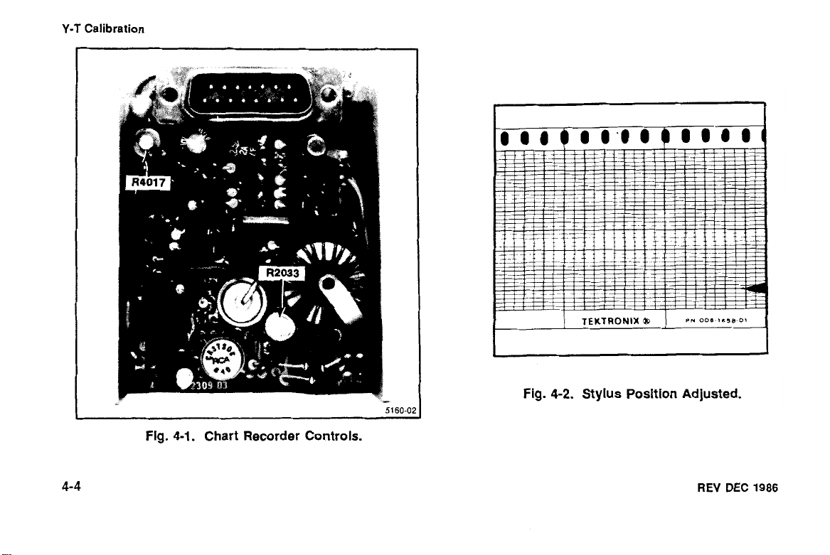
Fig.
4-1. Chart Recorder Controls.
5160-C
Fig.
4-2.
Stylus Position Adjusted.
REV
DEC
1986
Page 22
Y-T
Calibration
I
REV
DEC
1986
Micro
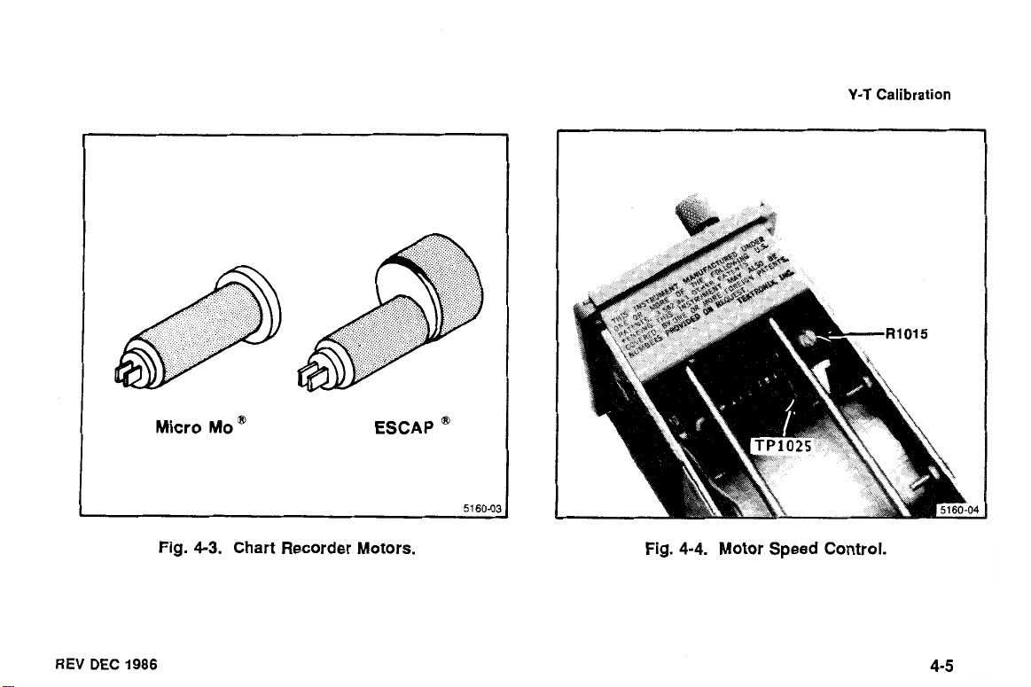
Fig.
4-3.
MO
@
Chart Recorder Motors.
ESCAP
@
51
60-03
Fig.
4-4. Motor Speed Control.
Page 23

Y-T
Calibration
Motor Speed Adjustment
To make the motor speed adjustment determine
which motor has been used in your instrument
(see Figure
Attach a voltmeter probe to P1025 on the Motor
Speed Control board (see Figure 4-4).
With the Chart Recorder on the Chart Recorder
Extender (067-1 071-00) push the RECORD button
and, while the chart is running, adjust R1015 for
1.55
Remove the Chart Recorder Extender and replace
the Chart Recorder in the plug-in module compart-
ment.
4-3).
V
(MicroMo motor) or 1.79 V (ESCAP motor).
REV
DEC
1986
Page 24
Y-T
Calibration
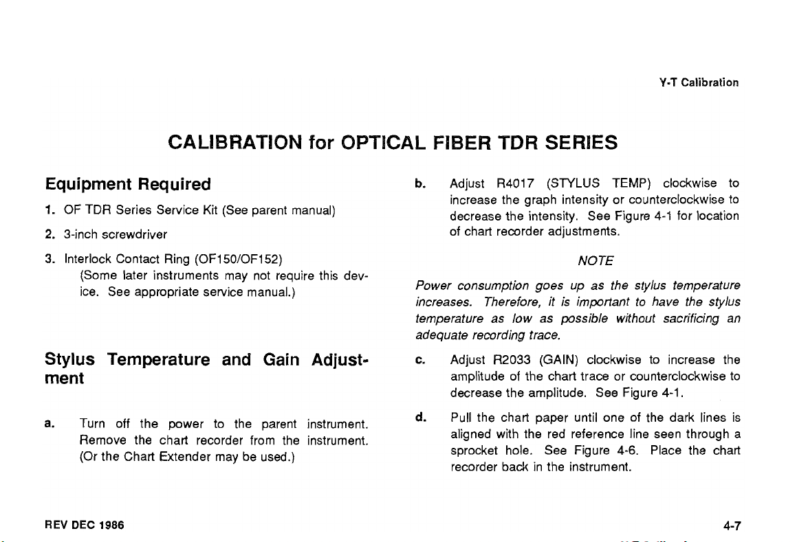
ATION
Equipment Required
1.
OF TDR Series Service Kit (See parent manual)
2.
3-inch screwdriver
3.
Interlock Contact Ring (OF150/OF152)
(Some later instruments may not require this dev-
ice. See appropriate service manual.)
Stylus
merit
a.
REV
Temperature and
Turn off the power to the parent instrument.
Remove the chart recorder from the instrument.
(Or the Chart Extender may be used.)
DEC 1986
Gain
for
OPTl
Adjust-
ER
TDR
b.
Adjust ~4017 (STYLUS TEMP) clockwise to
increase the graph intensity or counterclockwise to
decrease the intensity. See Figure
of chart recorder adjustments.
Power consumption goes up as the stylus temperature
increases. Therefore, it is important to have the stylus
temperature as low as possible without sacrificing an
adequate recording trace.
c.
Adjust R2033 (GAIN) clockwise to increase the
amplitude of the chart trace or counterclockwise to
decrease the amplitude. See Figure
d.
Pull the chart paper until one of the dark lines is
aligned with the red reference line seen through
sprocket hole. See Figure
recorder
back
SE
NOTE
4-6.
in the instrument.
4-1
for location
4-1.
Place the chart
a
Page 25

Y-T
Calibration
Motor Speed Adjustment
To make the motor speed adjustment, determine
which motor has been used in your instrument
(see Figure 4-3).
Attach a voltmeter probe to P1025 on the Motor
Speed control board (see Figure 4-4).
With the chart recorder connected to the Chart
Recorder Extender, push the RECORD switch and
monitor the voltage. Adjust R1015 for 1.55
(Micromotor) or 1.79 V (ESCAP).
Remove the Chart Recorder Extender, and plug in
the Chart Recorder.
V
Chart Recorder Checks
a.
On the OF150 and OF152, install an Interlock
Contact Ring. (Not necessary on OF151, or later
models of the OF150 and OF152).
Put the instrument in the Calibration Aid Mode.
b.
Set the DISTIDIV on the OF151lOF152 to 10
C.
(OF150 to
d.
Use the POSITION control to set the straight
line on the CRT to the center graticule line.
Push and release the RECORD switch.
e.
While the chart is running, adjust the STYLUS
f.
POSITION on the chart recorder so the line being
drawn is on the center graticule line of the chart.
2).
The LCD readout should be 9.
REV DEC
1986
Page 26
Y-T
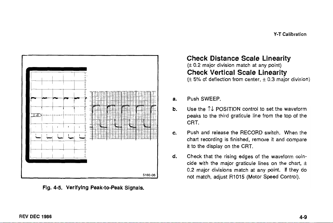
Calibration
Check Distance Scale Linearity
(+
0.2
major division match at any point)
Check Vertical Scale Linearity
(+
5O/0
of deflection from center,
Push SWEEP.
+
0.3
major division)
1
REV
DEC
Fig.
1986
4-5.
Verifying
Peak-to-Peak
Signals.
5160-06
Use the
peaks to the third graticule line from the top of the
CRT.
Push and release the RECORD switch. Wher; the
chart recording is finished, remove it and compare
it to the display on the CRT.
Check that the rising edges of the waveform coin-
cide with the major graticule lines on the chart,
0.2
not match, adjust
'?L
POSITION control to set the waveform
major divisions match at any point.
R1015
(Motor Speed Control).
If
they do
+
Page 27

Y-T
Calibration
e.
Check that the peak-to-peak signal on the
display coincides with the major graticule lines on
the chart,
cule line,
they do not match, adjust R2033 (GAIN).
f.
Remove the Chart Recorder Extender, and plug in
the Chart Recorder.
i
5% of deflection from the center grati-
f
0.3 major division (see Figure 4-5).
CRT
If
I
Alignment indi
(red line)
Fig.
Major Graticule Line
4-6.
Aligning
Chart Paper.
REV DEC
1986
Page 28

MAINTENANCE
Chart Recorder Repair
Except for the stylus and the rubber rollers, the chart
recorder is virtually maintenance free. Instructions for
replacing the stylus and the rubber rollers are given in
the following procedures. If replacement of other
mechanical parts should be necessary, refer to the
exploded views which are located in the mechanical
parts list section.
Changing the Stylus
1.
Disconnect P4012 from the circuit board (see Fig-
ure 5-1 a).
2.
Remove the two screws from the rear of the cover
and carefully remove the cover (see Figure 5-1
REV
DEC
1986
b).
Disconnect P1 01 3 from the circuit board.
3.
4.
Using a 0.05-inch allen wrench, loosen the set
screw and lift the assembly off the motor shaft.
Remove the holding screw from the stylus assem-
5.
bly.
6.
Separate the stylus and the holder.
Install a new stylus (Tek Part No. 11 9-0365-00).
7.
Loop the stylus wires around the motor shaft as
8.
shown in Figure 5-2. Connect P4012 and P1013.
Page 29
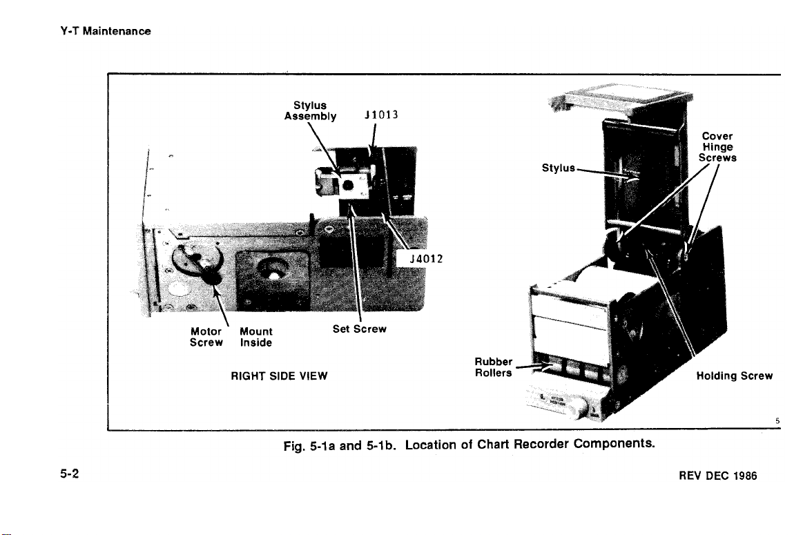
Y-T
Maintenance
Stylus
Assembly
\
Motor Mount Set screw
Screw Inside
RIGHT SIDE VIEW
J1013
Rubber
Rollers
Screw
5
Fig.
5-la and 5-1
b.
Location of
Chart
Recorder Components.
REV
DEC
1986
Page 30
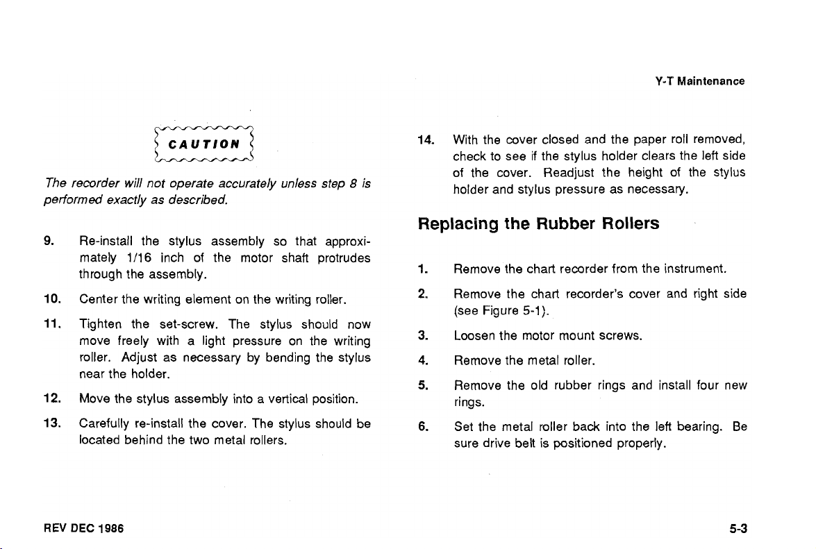
CAUTION
m
The recorder
performed exactly as described.
will
not operate accurately unless step 8 is
Y-T
14.
With the cover closed and the paper roll removed,
check to see if the stylus holder clears the left side
of the cover. Readjust the height of the stylus
holder and stylus pressure as necessary.
Maintenance
Re-install the stylus assembly so that approxi-
mately
through the assembly.
Center the writing element on the writing roller.
Tighten the set-screw. The stylus should now
move freely with a light pressure on the writing
roller. Adjust as necessary by bending the stylus
near the holder.
Move the stylus assembly into a vertical position.
Carefully re-install the cover. The stylus should be
located behind the two metal rollers.
REV
DEC
1986
1/16
inch of the motor shaft protrudes
Replacing
1.
Remove the chart recorder from the instrument.
2.
Remove the chart recorder's cover and right side
(see Figure
3.
Loosen the motor mount screws.
4.
Remove the metal roller.
5.
Remove the old rubber rings and install four new
rings.
6.
Set the metal roller back into the left bearing. Be
sure drive belt is positioned properly.
the
Rubber Rollers
5-1
).
Page 31
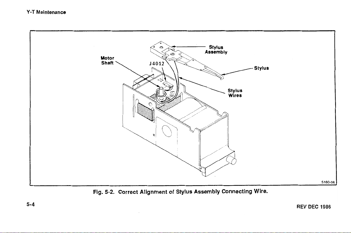
Y-T
Maintenance
Motor
Shaft
Stylus
5160
(
5-4
Fig.
5-2.
Correct Alignment of Stylus Assembly Connecting Wire.
REV
DEC
1986
Page 32

7.
Replace the right side.
8.
Move the motor slightly to take up slack in the belt
and tighten the motor mount screws.
CAUTION
Do not overtighten the drive belt.
9.
Position the motor
clear of the paper roll and drive roller.
LC
network (circuit board
A2)
Y-T
Maintenance
Save and re-use the package in which your instrument
was shipped. If the original packaging is unfit for use, or
not available, repackage the instrument as follows:
Obtain a carton of corrugated cardboard having
1.
inside dimensions of no less than six inches more
than the instrument dimensions; this will allow for
cushioning. Refer to the following table for carton
test strength requirements.
SHIPPING CARTON TEST STRENGTH
Gross
Weight
(Ib)
I
Carton
Test Strength
(Ib)
I
REPACKING
If the Tektronix instrument is to be shipped to a Tektronix
Service Center for service or repair, attach a tag show-
ing: owner (with address) and the name of an individual
at your firm that can be contacted, complete instrument
serial number and description of the service required.
REV DEC
1986
FOR
SHIPMENT
2.
Surround the instrument with polyethylene sheet-
ing to protect the finish of the instrument.
Page 33

Y-T
Maintenance
Cushion the instrument on all sides by tightly pack-
3.
ing dunnage or urethane foam between carton and
instrument, allowing three inches on all sides.
4. Seal carton with shipping tape or industrial stapler.
REV
DEC
1986
Page 34

OPTIONS
No options are planned for the Tektronix
REV
DEC
9986
Y-T
Chart Recorder
at
this time.
Page 35

REPLACEABLE ELECTRICAL PARTS
PARTS ORDERING INFORMATION
Replacement parts are available from or through your
local Tektronix, Inc., Field Office or representative.
Changes to Tektronix instruments are sometimes made to
accomodate improved components as they become avail-
able and to provide the benefit of the latest circuit
improvements developed in our engineering department.
It is therefore important, when ordering parts, to include
the following information in your order: part number,
instrument type or number, serial number, and
modification number, if applicable.
If a part you have ordered has been replaced with
or improved part, your local Tektronix Field Office or
representative will contact you concerning any change in
REV
JUN
1987
a
new
part number.
Change information, if any, is incorporated on each
when the change occurs.
List
of
Assemblies
A
list of assemblies can
Replaceable Electrical Parts list. The assemblies are
listed in numerical order. When the complete component
number
bly in which the par! is located.
of
a part is known, this list will identify the assem-
be
found at the beginning of the
page
Page 36

Replaceable
Electrical
Parts
-
YT-
CHART RECORDER
Cross 1ndex:Mfr. Code Number
The Mfr. Code Number to Manufacturer index for the
Electrical Parts List is located immediately following this
introduction. The Cross Index provides codes, names,
and addresses of manufacturers of components listed in
the Replaceable Electrical Parts List.
to
Manufacturer
Abbreviations
Abbreviations conform to American National Standard
Y1
.l.
Component Number
(Column One of the Electrical
Parts List)
A numbering method has been used to identify assem-
blies, subassemblies, and parts. Examples of this
numbering method and typical expansions are illustrated
below.
Example a.
Component number
Assembly Circuit
number number
1234
Read: Resistor
Example
Read: Resistor
Only the circuit number will appear on the diagrams and
circuit board illustrations. Each diagram and circuit board
illustration is clearly marked with the assembly number.
Assembly numbers are also marked on the mechanical
b.
of assembly
Component number
Assembly Subassembly Circuit
number number number
1234
of subassy 2 of Assy
23
23
REV
JUN
1987
Page 37

Replaceable
Electrical
Parts
-
Yf-
CHART
RECORDER
exploded views located in the Replaceable Mechanical
Parts list. The component number is obtained by adding
the assembly number prefix to the circuit number.
The parts list is divided and arranged by assemblies in
numerical sequence (e.g., assembly
subassemblies and parts, precedes
subassemblies and parts).
Chassis-mounted parts have no assembly number prefix
and are listed at
Parts list.
Tektronix Part No.
This indicates the part number to
a
replacement part from Tektronix.
REV
JUN
1987
the
end
of
(Column Two)
the Replaceable Electrical
be
Al,
with its
A2,
with its
used when ordering
SerialIModel No.
Column three indicates the serial number of the first
instrument in which the part was used. Column four indi-
cates the serial number of the last instrument in which the
part was used. No entries indicates that the part is used
in all instruments.
Name
In the Replaceable Electrical Parts list, the Item
separated from the description by a colon
space limitations, the ltem Name may sometimes appear
incomplete. For further ltem Name identification, the
Federal Cataloging Handbook
possible.
and Description
(Columns Three and Four)
(Column Five)
(:).
Because of
H6-1
can be utilized where
Name
US.
is
Page 38

Replaceable Electrical Parts
Mfr.
Code (Column
This indicates the code number of the actual manufac-
turer of the part. (The Mfr. Code Cross Index begins on
the following page.)
Mfr.
Part
Number (Column Seven)
This column lists the manufacturer's part number.
Six)
-
YT-
CHART RECORDER
REV
JUN
1987
Page 39

M fr.
Code
Manufacturer
CROSS INDEX
Replaceable Electrical Parts
-
MFR. CODE NUMBER TO MANUFACTURER
Address
City,
-
State,
YT-
CHART RECORDER
Zip
REV
UNITED CHEMICON INC
NEC ELECTRON INC
MURATA ERIE NORTH AMERICAN INC
ALLEN-BRADEY COMPANY
TEXAS INSTRUMENTS, INC
RCA CORPORATION
GENERAL ELECTRIC COMPANY
AVX CERAMICS
MOTOROLA INC
UNION CARBIDE CORP
ITT SEMICONDUCTORS DIVISION
AMETEK INCIRODAN DIV
BOURNS INCtTRIMPOT PRODUCTS DIV.
PORTESCAP, US
SPRAGUE ELECTRIC CO.
LITELFUSE, INC.
TEKTRONIX. INC.
JUN 1987
1128
LEXINGTON AVE
252
HUMBOLDT COURT
1148
FRANKLIN RD SE
1201
2ND STREET SOUTH
13500
N CENTRAL EXPRESSWAY
ROUTE
202
W GENESEE ST
19th
AVE SOUTH P 0
E MCWWELL RD., P.O. BOX
5005
1
1901
MADISON AVE
2905
BLUE STAR ST.
1200
COLUMBIA AVE.
730
FIFTH AVENUE
87
MARSHALL ST.
800
E. NORTHWEST HWY
P.O. BOX
500
BOX
867
20923
ROCHESTER, NY
SUNNYVALE, CA
MARIElTA, GA
MILWAUKEE, WI
DALLAS, TX
SOMERVILLE, NY
AUBURN, NY
MYRTLE BEACH, SC
PHOENIX, AZ
CLEVELAND.
WEST PALM BEACH, FL
ANAHEIM, CA
RIVERSIDE, CA
NEW YORK, NY
NORTH ADAMS,
DES PLAINES. IL
BEAVERTON OR
30067
72265
13021
85036
OH
92806
92507
14606
94086
53204
08876
44101
10019
MA
60016
97077
29577
01247
Page 40

Replaceable
Electrical
Parts - YT- CHART RECORDER
A1 - CHART RECORDER
Ckt.No. Part No.
Eff.
Dscont Name & Description
CKT BOARD ASSY: CHART RECORDER
(
MFD BEFORE 5/24/87)
CKT BOARD ASSY:CHART RECORDER
(
MFD 5/24/87 - 6/1/87)
CKT BOARD ASSY:CHART RECORDER
(
MFD AFTER 6/1/87)
SEMICOND DVC:S1.35V,O.lA
SEMICOND DVC:S1,20V,5A
SEMICOND DVC:S1,30V,150rnA
SEMICOND DVC:S1,55V,200rnA
SEMICOND DVC:S1,55V,200rnA
Code Number
SRI 55E103MAA
SR215E104MAA
T3688686M006ASC8
SM25VB-470
T368A 105M050AZ
56XBB501AE
FUSE,CARTRIDGE:2A,125\1,5
SEC
REV
JUN
1987
Page 41

A1
-
CHART RECORDER
Ckt.No.
Part
No.
(cont)
Replaceable Electrical
Eff.
Dscont Name & Description Code Number
(SEE 1-62 RMPL)
(SEE 1-62 RMPL)
(SEE 1-62 RMPL)
(SEE 1-62 RMPL)
(SEE 1-62 RMPL)
(SEE 1-62 RMPL)
XSTR:SI,PNP 0471 3
(
MFD
BEFORE JUNE 1,1987)
XSTR:SI,PNP 0471 3
(
MFD
AFTER JUNE 1,1987)
XSTR:SI.PNP 01295
XSTR:SI,NPN 03508
XSTR:SI,PNP 03508
XSTR:SI,NPN 04713
Parts - YT- CHART RECORDER
REV
JUN
1987
Page 42

Replaceable Electrical Parts - YT- CHART RECORDER
A1 - CHART RECORDER
Ckt.No. Part No.
(cont)
Eff.
Dscont Name & Description
XSTR:SI,NPN
XSTR:SI,PNP
XSTR:SI,NPN,SEL FROM MJE521
Code Number
REV JUN
1987
Page 43

Replaceable Electrical Parts
-
YT-
CHART
RECORDER
REV
A1 - CHART RECORDER
Ckt.No.
JUN
1987
Part
No.
Eff.
(cont)
Dscont
Name
8
Description
Code
Number
CB6235
CB6235
CB1035
3329
P-L58-2a7
SPSN 0485503U
CB2435
Page 44

Replaceable Electrical Parts
A1
-
CHART RECORDER
Ckt.No.
Part
-
YT-
CHART RECORDER
(cont)
No.
Eff.
Dscont
Name & Description
Code Number
REV JUN
1987
Page 45

Replaceable Electrical
Parts
-
YT- CHART RECORDER
REV
A1 - CHART RECORDER
JUN
Ckt.No.
1987
Part
No.
(cont)
Eff.
Dscont
Name
&
Description
Code
Number
Page 46

Replaceable Electrical Parts - YT- CHART RECORDER
A2
-
MOTOR
Ckt.No. Part No.
SPEED
CONTROL
Eff.
Dscont Name 8 Description Code Number
CKT BD ASSY:MOTOR SPEED CONTROL
CAP.,FXD,CER DI:0.022p F,20%,50V
CAP.,FXD.CER DI:O.lp F,+80-20%,50V
SEMICOND DVC:FE,S1,25VslmA
(SEE 1-60 RMPL)
XSTR:SI,NPN
XSTR:SI,NPN
RES.,VAR,NONWW:2OK OHM,10%,0.5W
RES.,FXD,CMPSN:62K OHM,5%.0.125W
RES.,FXD,CMPSN:130K OHM,5%,0.125W
RES.,FXD,CMPSN:SlK OHM,5%,0.125W
RES.,FXD,CMPSN:100K OHM,5%,0.125W
RES.,FXD,CMPSN:6.2 OHM,5%,0.25W
REV
JUN
1987
Page 47

Replaceable Electrical Parts
-
YT-
CHART
RECORDER
REV JUN
A2 - MOTOR
Ckt.No.
1987
SPEED
Part
No.
CONTROL
Eff.
(cont)
Dscont Name & Description
(SEE
1-60
RMPL)
Code
Number
Page 48

Replaceable Electrical Parts - YT- CHART RECORDER
CHASSIS PARTS AND WlRE ASSEMBLIES
Ckt.No.
DS0282 150-1040-04 LED:RED,690nm,40mA MAX WILEADS & HLDR (1 50X) 80009 150-1040-01
Part
No.
Eff.
Dscont
Name & Description
-
CHASSIS MOUNTED PARTS
Code
Number
-
00182 151-0313-01 XSTR:NPN,SI FPT-106 W/HOLDER,WIRE
-
W1
001
WlRE ASSEMBLIES
198-2796-01 WIRE SET ELEC:670-1742-06 80009 198-2796-01
-
& CONN 80009 151 -031 3-01
REV
JUN
1987
Page 49

DIAGRAMS
AND
CIRCUIT
BOARD
ILLUSTRATIONS
Symbols
Graphic symbols and class designation letters are based
on ANSl Standard Y32.2-1975.
Logic symbology is based on ANSl Y32.12-1973 in terms
of positive logic. Logic symbols depict the logic function
performed and may differ from the manufacturer's data.
The overline on a signal name indicates that the signal
performs its intended function when it is in low state.
Abbreviations are based on ANSl Y1
Other ANSl standards that are used in the preparation of
diagrams by Tektronix, Inc. are:
Y14.15- 1966 Drafting Practices
Y14.2
-
REV
1973
DEC 1986
Line Conventions and Lettering
.l
-1
972.
-
Y10.5
1968 Letter Symbols for Quantities
Used in Electrical Science and
Electrical Engineering
American National Standards Institute
1430 Broadway
New York, New York 1001
8
Component Values
Electrical components shown on the diagrams are in the
following units unless noted otherwise:
Capacitors
Resistors
-
Values one or greater are in pico-
farads
(p
F).
Values less than one
are in microfarads
-
Ohms
(R
).
(p
F).
Page 50

Diagrams
Assembly Numbers
Each assembly in the instrument is assigned an assem-
bly number (e.g.,
on the circuit board outline on the diagram, in the title for
circuit board component location illustrations, and in the
lookup table for the schematic and corresponding com-
ponent locator illustration. The Replaceable Electrical
Parts list is arranged by assemblies in numerical
sequence. The components are listed alphabetically and
numerically by component number.
-
Y-T
Chart Recorder
--
The
information
below may appear in this manual
and
special symbols
and Grid Coordinates
A13).
The assembly number appears
--
The schematic diagram and circuit board component
A
location illustration have grids.
grid coordinates is provided for ease of locating the com-
ponent. Only the components illustrated on the facing
diagram are listed in the lookup table. When more than
one schematic diagram is used to illustrate circuitry on a
circuit board, the circuit board illustration may only
appear opposite the first diagram on which it is illus-
trated. The lookup table will list the diagram number of
other diagrams on which the circuitry of that circuit board
appears.
lookup table with the
REV
DEC
1986
Page 51

COMPONENT NUMBER EXAMPLE
REV
DEC
1986
-
t5Vi
ASSEMBLY CIRCUIT No
<h
FUNCTIONAL NAME
W0450A4
ERROR
AMPLIF'ER
C
,-P O("a
'h
'C')
FRONT PANEL
DENOTES A
PANEL CONTROL,
CONNECTOR, OR
INDICATOR
Page 52

PLUG
SPEED
STYLUS
t5V
IN
5ENS-
HEAT
-
-
(FROM
0
01
BE)
'Q
+5Y
-5V
GNO-
GND-
PAPER
)POOL
-
*+BY.
-8V
CHART-
FOR
1500
5ERIE5
--
CHART RECORDER
l
FROM
P1036-L
=
tozO
,CUbRT
PAPER
a
4
Page 53

Diagrams
-
Y-T
Chart
Recorder
REV
DEC
1986
ASSEMBLY
CIRCUIT SCHEM BOARD
NUMBER LOCATION LOCATION
C2034
84
c2
A1
CIRCUIT SCHEM BOARD
NUMBER LOCATION LOCATION
01
5 C1 A1
Q1
CIRCUIT SCHEM BOARD
NUMBER LOCATION LOCATIOI
R2034 D5 C2
Page 54

Diagrams
-
Y-T
Chart Recorder
5
J4037BACK
J4036 BACK
1
Fig.
8-1.
BACK.
Y-T
Chart Recorder Circuit Board.
5160-10
REV DEC
1986
Page 55

Diagrams
-
Y-T
Chart Recorder
REV
DEC
1986
CIRCUIT SCHEM BOARD
NUMBER
C201 9
C3026
CR2031 D1 C2
Q1 024 F1 B1
Q1039 F
R1015 El A1
LOCATION LOCATION
E2 A2
D1 B3
1
Fig.
B1
8-2.
ASSEMBLY
CIRCUIT SCHEM BOARD
NUMBER LOCATION
R201 4 E
R201 5
R201
6
R2024 El D2
R2025
R2026
R2029
R2035 E2 A3
A
B
A2
LOCATION
l
E
l
D1 A2
El B2
E2 B2
El B2
A2
A2
C
CIRCUIT SCHEM BOARD
NUMBER
R3015 E
R301 9
R3025 E2 B3
TPI 025 D2 B1
U2035A E2 C2
U20358 El C2
Motor Speed Control Circuit Board.
LOCATION LOCATION
l
E2 A3
A3
Page 56

Diagrams
-
Y-T
Chart
Recorder
IRCUIT BOARD
UMBER LOCATION
:IRCUlT BOARD
IUMBER LOCATDN
:IRCUIT BOARD
UMBER LCCATIOh
R2m5
R2m6
W017 83
W018 B3
R3018 B3
R3010 B3
R3021
R3022
R3023 82
R3024
R3025
R3026 B2
R3027 B2
R3028 83
R3030
R3031
R3034
R4017 A2
R4023 C3
R4025 B2
R4027 B2
R4033 C3
Fig.
82
D2
W
c3
W
C3
W
W
c3
8-3.
Modified Chart Recorder Board.
REV
JUN
1987
Page 57

EPLACEABLE
ME
PARTS ORDERING INFORMATION
Replacement parts are available from or through your
local Tektronix, Inc. Field Office or representative.
Changes to Tektronix instruments are sometimes made
to accomodate improved components as the become
available and to give you the benefit of the latest circuit
improvements developed in our engineering department.
It is, therefore, important, when ordering parts, to include
the following information in your order: Part number,
instrument type or number, serial number, and
modification number (if applicable).
REV
DEC
1986
ANlCAL
If
a part you have ordered has been replaced with a new
or improved part, your local Tektronix, Inc. Field Office
representative will contact you concerning any change in
part number.
Change information, if any, is incorporated on each
when the change occurs.
PAR
or
page
SPECIAL NOTES AND SYMBOLS
X000
OOX
Part first added at this serial number
Part removed after this serial number
Page 58

Replaceable Mechanical Parts
-
Y-T
Chart
Recorder
INDENTATION SYSTEM
This mechanical parts list is indented to indicate item
relationships. The following is an example of the inden-
tation system used in the description column:
&
Name
Assembly andlor Component
Attaching parts for this Assembly or Component
.
Detail Part of Assy or Component
.
Attaching parts for Detail Part
.
.
Parts of Detail Part
.
.
Attaching parts for Parts of Detail Part
Attaching Parts always appear in the same indentation
as the item it mounts, while the detail parts are indented
to the right. Indented items are part of, and included
Description
___*___
---*---
with, the next higher indentation. The separation
-
-
symbol indicates the end of attaching parts.
Attaching parts must be purchased separately,
unless otherwise specified.
-
- - * -
FIGURE AND INDEX NUMBERS
Items in this section are referenced by figure and index
numbers to the illustrations showing that part.
ITEM NAME
In this parts list, an ltem Name is separated from the
(:).
description by a colon
an ltem Name may sometimes appear as incomplete.
For further Item Name identification, the
Cataloging Handbook,
ble.
Because of space limitations,
U.S.
H6-1,
can be utilized where possi-
REV
Federal
DEC
1986
Page 59

If
ACTR
ADPTR
ALEN
AL
ASSEM
ASSY
ATTEN
AWG
BD
BRKT
BRS
BRZ
BSHG
CAB
CAP
CE R
CHAS
CKT
COMP
CONN
CVR
CPLG
CRT
DEG
DWR
INCH
NUMBER SIZE
ACNATOR
ADAPTER
ALGNMENT
ALUMINUM
ASSEMBLED
ASSEMBLY
ATTENUATOR
AMERICAN WlRE GUAGE
BOARD
BRACKET
BRASS
BRONZE
BUSHING
CABINET
CAPACITOR
CERAMIC
CHASSIS
CIRCUIT
COMPOSlTlON
CONNECTOR
COVER
COUPLING
CATHODE RAY TUBE
DEGREE
DRAWER
ELECTRN
ELEC
ELCTLT
ELEM
EPL
EQPT
EXT
FIL
FLEX
FLH
FLTR
FR
FSTNR
FT
FXD
GSKT
HDL
W
H
HEXHD
HEXSOC
HLCPS
HLEXT
HV
IC
ID
IDENT IDENTIFICATION
IMPLR IMPELLER
ELECTRON
ELECTRICAL
ELECTROLYTIC
ELEMENT
ELECTRICAL PARTS LIST
EQUIPMENT
EXTERNAL
FILLISTER HEAD
FLEXIBLE
FLAT HEAD
FILTER
or
FRAME
FASTENER
FOOT
FIXED
GASKET
HANDLE
HEXAGON
HEXAGONAL HEAD
HEXAGONAL SOCKET
HELICAL COMPRESSION
HELICAL EXTENSION
HIGH VOLTAGE
INTEGRATED CIRCUIT
INSIDE DIAMETER
FRONT
ABBREVIATIONS
IN INCH
INCAND
INSUL
INTL
LPHLDR
MCH
MECH
NIP
NONWW
ORD BY DESCR
OD
OVH
PHBRZ
PL
PLSTC
PN
PNH
PWR
RCPT
RE•˜
RGD
RLF
RTNR
SCH
SCOPE
SCR
SE
Replaceable Mechanical Parts - Y-T
SCT
INCANDESCENT
INSULATOR
INTERNAL
LAMP HOLDER
MACHINE
MECHANICAL
NIPPLE
NOT WlRE WOUND
ORDER BY DESCRIPTION
OUTSIDE DIAMETER
OVAL HEAD
PHOSPHOR BRONZE
or
PLATE
PLAIN
PLASTIC
PART NUMBER
PAN HEAD
POWER
RECEPTACLE
RESISTOR
RIGID
RELIEF
RETAINER
SOCKET HEAD
OSCILLOSCOPE
SCREW
SINGLE END
SEMICOND
SHLD
SHLDR
SKT
•˜L
SLVG
SPR
SQ
SST
STL
SW
T
TERM
THD
THK
TNSN
TPG
TRH
v
VA R
W1
WSHR
W
XFMR
XSTR
Chart
Recorder
SECTION
SEMICONDUCTOR
SHIELD
SHOULDERED
SOCKET
SLIDE
SLEEVING
SPRING
.SQUARE
STAINLESS STEEL
STEEL
SWITCH
TUBE
TERMINAL
THREAD
THICK
TENSION
TAPPING
TRUSS HEAD
VOLTAGE
VARIABLE
WITH
WASHER
WlRE WOUND
TRANSFORMER
TRANSISTOR
REV
DEC
1986
Page 60

Replaceable Mechanical Parts
-
Y-T
Chart Recorder
Mfr.
Code Manufacturer
NORTHWEST FASTENER SALES
LEWlS SCREW CO
PLASTOCK, INC.
AMP. INC.
MITE CORPORATION
FREEWAY CORPORATION
GRAPHIC CONTROLS CORP.
BERG ELECTRONICS. INC.
USM CORP., PARKER-KALON FASTENER DIV.
PORTESCAP
STANDARD PRESSED STEEL CO.
ALLEN MFG. CO.
ITT CANNON ELECTRIC
FISCHER SPECIAL MFG. CO.
HOLQKROME CO.
WALDES, KOHINOOR, INC.
WROUGHT WASHER MFG. CO.
TEKTRONIX, INC.
CROSS INDEX-MFR. CODE NUMBER
U
S
TO
MANUFACTURER
Address
7923 SW CIRRUS DRIVE
41 14 SOUTH PEORIA
380 CHESTNUT ST
P.0.BOX
446 BLAKE STREET
9301 ALLEN DRIVE
YOUK EXPRESSWAY
730 FIFTH AVENUE
BENSON EAST
P.O. DRAWER 570
666 E. DYER RD.
446 MORGAN STREET
31 BROOK ST. WEST
47-16 AUSTEL PLACE
2100 S.
P.O. BOX 500
3608
0
BAY ST.
City, State,
BEAVERTON, OR 97005
CHICAGO, IL 60609
NORWOOD,
HARRISBURG, PA 171
NEW HAVEN, CT 06515
CLEVELAND,
NEW CUMBERLAND, PA 17070
CAMPBELLSVILLE,
NEW YORK. NY 10019
JENKINTOWN, PA 19046
HARTFORD, CT 061 01
SANTA ANA, CA 92702
CINCINNATI, OH 45206
HARTFORD, CT 061 10
LONG ISLAND, NY 11 101
MILWAUKIE, WI 53207
BEAVERTON, OR 97077
Zip
NJ
OH
07648
44125
KY
05
42718
REV
DEC
1986
Page 61

Mfr.
Code
Manufacturer
Replaceable Mechanical Parts - Y-T
CROSS INDEX-MFR. CODE NUMBER TO MANUFACTURER
Address
City,
State,
Chart Recorder
Zip
REV DEC
83259 PARKER SEAL CO-OSSEAL, 10567 JEFFERSON BLVD
83309
83385 CENTRAL SCREW CO. 2530 CRESCENT DRIVE
86928 SEASTROM
95987 WECKESSER CO., INC.
ELECTRICAL SPECIALIN CO 21 3 E HARRIS AVE
MFG.
CO., INC. 701 SONORA AVENUE
4444
WEST IRVING PARK RD. CHICAGO, IL 60641
1986
CULVER CITY, CA 90231
SOUTH SAN FRANCISCO, CA 94080
BROADVIEW, IL 60153
GLENDALE, CA 91
201
Page 62

Replaceable Mechanical
Parts
-
Y-T
Chart Recorder
Fig.&
Index Tektronix SeriaVModel No.
No.
Part.No.
Eff.
Dscont.
Qty.
Name & Description
CHART RECORDER:OF15X ONLY
PLATE,BACKING:CHART PAPER
(ATTACHING PARTS)
SCREW,MACHINE:2-56 X ,250 FLH STL
---
---
BUSHING,SLEEVE:O.I31 ID X 0.125 L
.
KNOB:THUMBSCREW,CLEAR,O.I
. .
SETSCREW:4-40 X 0.125,STL,BLK,OXD
WASHER,FLAT:0.13 ID
FRAME SECTION,CABINET:LOWER FROM
(ATTACHING PARTS)
SCREW,TPG,TF:4-40 X 0.25 FLH STL
--F
---
RING,RETAINING:TYPE EXT.0.125 ID SFT
PIN,STR,THD:0.125 DIA X 6.417 L,AL
SHAFT,EXTENSION:0.125
CPLG,SHAFT,RGD:0.128 ID X 0.312 OD,AL
BEZEL ASSEMBLY:GENERAL PURPOSE
(ATTACHING PARTS)
NUT,SLEEVE:4-40 X 0.312,HEX,BRS
SCREW,MACHINE:4-40 X 0.25 FLH STL
X
0.375 OD.0.01 THK,NYLON
OD
X 4.44 L,AL
2 X 0.37
Mfr. Mfr.Part
Code Number
ORD BY DESCR
358-0378-00
366-0650-00
ORD BY DESCR
ORD BY DESCR
426-0852-01
ORD BY DESCR
220-0629-00
ORD BY DESCR
REV
JAN
1987
Page 63
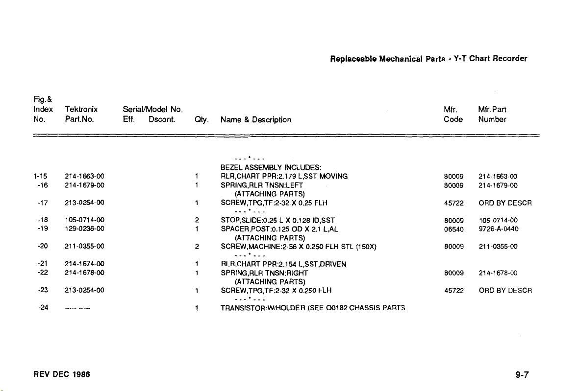
Fig.&
Index Tektronix SerialIModel No.
Eff.
No. PartNo.
Dscont.
Qty.
Name & Description
-_-*__-
BEZEL ASSEMBLY INCLUDES:
RLR,CHART PPR:2.179 L,SST MOVING
SPRING,RLR TNSN:LEFT
(ATTACHING PARTS)
SCREW,Tffi,TF:2-32
-__'___
STOP,SLIDE:O.25
SPACER,POST:O.I25 OD
(ATTACHING PARTS)
SCREW,MACHINE:2-56
--_*___
RLR,CHART PPR:2.154 L,SST,DRIVEN
SPRING,RLR TNSN:RIGHT
(ATTACHING PARTS)
SCREW,TPG,TF:2-32
---*___
TRANSIST0R:WlHOLDER (SEE
L
X
Replaceable Mechanical Parts
X
0.25 FLH
0.128 ID.SST
X
2.1 L,AL
X
0.250 FLH STL (150X)
X
0.250 FLH
Q01
82 CHASSIS PARTS
-
Y-T
Chart
Recorder
Mfr.
Mfr.Part
Code Number
BY
ORD
ORD BY DESCR
DESCR
REV
DEC
1986
Page 64

Replaceable Mechanical Parts
-
Y-T
Chart Recorder
Fig.&
Index Tektronix SeriallModel No.
No.
Part.No. Eff. Dscont.
Qty.
Name & Description
(ATTACHING PARTS)
SCREW,TPG,TF:2-32 X 0.250 FLH
___*___
HINGE HALF:STYLUS,MOVING UPPER
(ATTACHING PARTS)
NUT,PLAIN HEX:4-40 X 0.188,BRS CDPL
SCREW,MACHINE:4-40 X 0.250.PNH,STL CD PL
PIN.HINGE:0.75 L X 0.125 OD SST
___*___
HINGE HALF:SlYLUS,STATIONARY
(ATTACHING PARTS)
SCREW,MACHINE:4-40 X O.Z50,PNH,STL CD PL
___*___
HINGE HALF:STYLUS,MOVING LOWER
SPRING,PIN HINGE
STYLUS:CHT RCDR:W/W
(ATACHING PARTS)
SCR,ASSEM WSHR:6-32 X 0.438.DBL SEMS (OF15X)
TERMINAL LUG:0.146 ID
Mfr. Mfr.Part
Code Number
ORD BY DESCR
21 4-1 682-00
12161-50
ORD BY DESCR
21 4-1 749-00
21 4-1 681 -00
ORD BY DESCR
214-1682-01
21 4-1 680-00
11 9-0365-00
21 1-0602-00
5442-7
REV DEC
1986
Page 65

Fig.&
Index Tektronix SerialIModel No.
No.
Part.No.
Eff.
Dscont.
Qty.
Name & Description
Replaceable
Mechanical
Parts
Mfr.
Code
-
Y-T
Chart
Mfr.Part
Number
Recorder
REV
DEC
1986
SCRASSEM WSHR:6-32 X 0.312,DBL SEMS (150X)
___*___
STYLUS MOTOR WMIRES
(SEE B0295 CHASSIS PARTS)
HOLDER,PAPER:CHART ROLL
(AlTACHING PARTS)
SCREW,MACHINE:2-56 X 0.375 FLH
___*___
LED ASSY (SEE DS0282, CHASSIS PARTS)
(ATTACHING PARTS)
SCREW,TPG,TF:Z-32 X 0.25 FLH STL
CLAMP,LOOP:0.093 ID,NYLON
NUT,PLAIN HEX:2-56 X 0.188 BRS
WASHER,LOCK:SPLTT,O.02 THK,STL CD PL
WASHER,FLAT:0.093
-__*__-
FRONT SECTION,CHART:RIGHT
(ATTACHING PARTS)
SCREW,MACHINE:2-56 X 0.250 FLH STL
___*_._
BELT,POZ DRIVE:44 TOOTH,3.59 L X0.125 W
ID
CU BE
X 0.281 OD
ORD BY DESCR
352-0296-00
ORD BY DESCR
ORD BY DESCR
3132-2
12157-50
ORD BY DESCR
ORD BY DESCR
426-0838-01
BY
DESCR
ORD
44MX18-40DP
Page 66

Replaceable Mechanical Parts
-
Y-T
Chart Recorder
Fig.&
Index Tektronix SetiaVModel No.
No.
Part.No.
Eff.
Dscont
Qty.
Name & Desaiption
SPROCKET,WHEEL20 TOOTH.NYLON
BRACKET.CMPNT:MOTORAL
(ATTACHING PARTS)
SCRJCXZZM WSHR:4-40 X 0.312 DOUBLE SEMS
___*___
MOTOR.DC: (SEE -1, CHASSIS PARTS)
(ATTACHING PARTS)
SCREW,MACHINE:l-72
___.___
CKT BOARD ASSY:MOTOR SPEED
.TERMINAL.PIN:0.365 L X 0.025
(ATTACHING PARTS)
NUT,PLAIN HEX2-56
SCR,ASS€M WSHR2-56
_--*__.
CKT BOARD ASSYCHART RECORDER (SEE A1 REPL)
.TERMINAL.PIN:0.365 L X 0.025
.CONNECTOR,RCPT ELECEKT
.RES,VAR: (SEE A1
(ATTACHING PARTS)
NUT.PLAIN HEX:.25-32 X 0.312 BRS
X
0.1 25,FLH STL
X
0.188 BRS
X
0250 DOUBLE SEMS
R2034
REPL)
COHTROL
PH
BR2 GOLD
PH
BR2 GOLD
BD
MT.15 CONTACT
(SEE
A2
REPL)
Mfr.
Code
Mfr.Part
Number
ORD
BY
ORD
BY
12157-50
ORD
BY
REV
DEC
DESCR
DESCR
DESCR
1986
Page 67

Fig.
&
index Tektronix SerialIModel No.
Eff.
No. Part.No.
Dscont.
Qty.
Name & Description
Replaceable Mechanical Parts
Mfr. Mfr. Part
Code Number
-
Y-T
Chart Recorder
REV
DEC
1986
WASHER,FLAT:0.25 ID X 0.02 THK,STL
WASHER,FLAT:0.265 ID X 0.01 THK,TEFLON
___*_-_
CLAMP LOOP:0.3 DIA,PLASTIC
SOCKET,PIN TERM:U/W 0.019 DIA PINS
SPACER,POST:2.024 L,W12-56 THD EA END,AL
(ATTACHING PARTS)
SCREW,MACHINE:2-56 X 0.250
___.___
RLR,CHART PPR:0.250 DIA X 2.154 L
RLR,CHART PPR:0.125 DIA X 2.154 L
SPROCKET WHEEL:W/B?ISHING
RLR,CHART PPR:DRIVE CORE
PACKIFiG,PREFMD:0.549 ID
BUSHING,PLASTIC:0.730 DIA X 0.080 Wl.260 DIA
FRONT SECTION,CHART:LEFT
X
0.103 XSECT
ORD
BY
21 0-0992-00
343-0089-00
2-330808-7
ORD
21 4-1662-00
21 4-1 664-00
401 -0186.02
21 4-1 675-01
21 13En45D
426-0837-02
DESCR
129-0327-00
BY
DESCR
Page 68

Replaceable Mechanical
Parts
-
Y-T
Chart Recorder
REV DEC
1986
Page 69

Replaceable Mechanical Parts
-
Y-T
Chart Recorder
FIGURE
Y-T
CHART PAPER
9-2
9-1
3
Page 70

Replaceable
Mechanical Parts
Fig.&
Index Tektronix SeriaVModel No. Mfr. Mfr.Part
No. Part.No.
-
Y-T
Chart Recorder
Eff.
Dscont.
Qty.
Name & Description Code
Number
1 PAPER,RCDG,CHART:GRAY
(150X ONLY)
1 PAPE R,RCDG,CHART:GRAY 17405 ORD BY DESCR
(OF15X ONLY)
80009
006-1658-01
Page 71

ACCESSORIES
Standard Accessories
1 Instruction Manual (070-51 60-00)
1 Roll of Chart Paper (006-361 8-00)
(OF TDR Series only)
1
Roll
of
Chart Paper (006-1 658-01
(1 500 TDR Series only)
REV
DEC 1986
Optional Accessories
Chart Paper, 25-Roll Pack
(OF TDR Series only)
)
Chart Paper, 100-Roll Pack
(OF TDR Series only)
Chart Paper, 100-Roll Pack (006-1 658-02)
(1500 Series only)
(006-361 8-01)
(006-361 8-02)
 Loading...