

Page 1

xx
WVR6020, WVR7020, WVR7120,
WVR6100 Opt. MB, WVR7000 Opt. MB, and
WVR7100 Opt. MB Waveform Rasterizers, and
ZZZ
WVRRFP Remote Front Panel
Service Manual
*P077223500*
077-2235-00
Page 2

Page 3

xx
WVR6020, WVR7020, WVR7120,
WVR6100 Opt. MB, WVR7000 Opt. MB, and
WVR7100 Opt. M B Waveform Rasterizers, and
ZZZ
WVRRFP Remote Front Panel
Service Manual
Revision A
www.tektronix.com
077-2235-00
Page 4

Copyright © Tektronix. All rights reserved. Licensed software products are owned by Tektronix or its subsidiaries
or suppliers, and are protected by national copyright laws and international treaty provisions.
Tektronix products are covered by U.S. and foreign patents, issued and pending. Information in this publication
supersedes that in all previously published material. Specifications and price change privileges reserved.
TEKTRONIX and TEK are registered trademarks of Tektronix, Inc.
Contacting Tektronix
Tektronix, Inc.
14200 SW Karl Braun Drive
P.O. B o x 5 0 0
Beaverto
USA
For product information, sales, service, and technical support:
n, OR 97077
In North America, call 1-800-833-9200.
Worl dwid e, vis it www.tektronix.com to find contacts in your area.
Page 5

Warranty
Tektronix warrants that this p roduct will be free from defects in materials and workmanship for a period of one (1)
year from the date of shipment. If any such product proves defective during this warranty period, Tektronix, at its
option, either will repair the defective product without charge for parts and labor, or will provide a replacement
in exchange for the defective product. Parts, modules and replacement products used by Tektronix for warranty
work may be n
the property of Tektronix.
ew or reconditioned to like new performance. All replaced parts, modules and products become
In order to o
the warranty period and make suitable arrangements for the performance of service. Customer shall be responsible
for packaging and shipping the defective product to the service center designated by Tektronix, with shipping
charges prepaid. Tektronix shall pay for the return of the product to Customer if the shipment is to a location within
the country in which the Tektronix service center is located. Customer shall be responsible for paying all shipping
charges, duties, taxes, and any other charges for products returned to any other locations.
This warranty shall not apply to any defect, failure or damage caused by improper use or improper or inadequate
maintenance and care. Tektronix shall not be obligated to furnish service under this warranty a) to repair damage
result
b) to repair damage resulting from improper use or connection to incompatible equipment; c) to repair any damage
or malfunction caused by the use of non-Tektronix supplies; or d) to service a product that has been modified or
integrated with other products when the effect of such modification or integration increases the time or difficulty
of servicing the product.
THIS WARRANTY IS GIVEN BY TEKTRONIX WITH RESPECT TO THE PRODUCT IN LIEU OF ANY
OTHER WARRANTIES, EXPRESS OR IMPLIED. TEKTRONIX AND ITS VENDORS DISCLAIM ANY
IMPLIED WARRANTIES OF MERCHANTABILITY OR FITNESS FOR A PARTICULAR PURPOSE.
TRONIX’ RESPONSIBILITY TO REPAIR OR REPLACE DEFECTIVE PRODUCTS IS THE SOLE
TEK
AND EXCLUSIVE REMEDY PROVIDED TO THE CUSTOMER FOR BREACH OF THIS WARRANTY.
TEKTRONIX AND ITS VENDORS WILL NOT BE LIABLE FOR A NY INDIRECT, SPECIAL, INCIDENTAL,
OR CONSEQUENTIAL DAMAGES IRRESPECTIVE OF WHETHER TEKTRONIX OR THE VENDOR HAS
ADVANCE NOTICE O F THE POSSIBILITY OF SUCH DAMAGES.
[W2 – 15AUG04]
btain service under this warranty, Customer must notify Tektronix of the defect before the expiration of
ing from attempts by personnel other than Tektronix representatives to install, repair or service the product;
Page 6

Page 7

Table of Contents
General Safety Summary .......................................................................................... v
Service Safety Summary.................... ................................ ................................ ..... vii
Preface.............................................................................................................. ix
Manual Conventions...................................... ................................ .................... ix
Related Manuals ........ .................................. ................................ .................... ix
Introduction
Introduction ....................................................................................................... 1-1
Service Strategy..... .................................. ................................ ....................... 1-1
Specifications................................ ................................ ................................. 1-1
Performance Verification................. ................................ .................................. . 1-1
Options and Accessories .................................................................................... 1-1
Configurations................................................................................................ 1-1
Hardware Installation............................. .................................. ......................... 1-2
Product Upgrade ............................................................................................. 1-2
Operating Information....................................................................................... 1-2
Theory of Operation
Theory of Operation. ................................ ................................ ............................. 2-1
Serial Digital Input ......... .................................. ................................ ............... 2-2
Composite Input ............................................................................................. 2-2
Reference Input .............................................................................................. 2-2
Digital Waveform Processing Engine .......................... ................................ ........... 2-2
Rasterizing Engine........................................................................................... 2-4
Recursion and Picture Processing Engine................................................................. 2-4
Control Processor ............................................................................................ 2-4
Front Panel ...... ................................ ................................ ............................. 2-5
LTC........................... ................................ .................................. ............... 2-5
Audio Option Board ................ ................................ ................................ ......... 2-5
Audio Processing ..... ................................ ................................ ....................... 2-6
Audio Inputs..................... .................................. ................................ ........... 2-6
Audio Outputs................................................................................................ 2-6
Option EYE/PHY............................................................................................ 2-6
Fault LED and
Power Supply and Distribution........................................................................... 2-10
Fan Block Diagram....................................... ................................ . 2-8
WVR6020, WVR7020, and WVR7120 Waveform Rasterizers Service Manual i
Page 8

Table of Contents
Adjustment Procedures
Adjustments....................................................................................................... 3-1
Maintenance
General Mai
Preventing ESD .............................................................................................. 4-1
Inspection and Cleaning.................................... .................................. ............... 4-2
Troubleshooting... ................................ ................................ ........................... 4-5
Detailed Troubleshooting Procedures ................................................................... 4-11
Repackaging Instructions ...................................................................................... 4-27
Packagi
Shipping to the Service Center.... ................................ .................................. ..... 4-27
ntenance............ ................................ .................................. ............... 4-1
ng.................. .................................. ................................ ............... 4-27
Replaceable Mechanical Parts
Replaceable Parts ................ ................................ ................................ ................. 5-1
Ordering Information ................................................................................. 5-1
Parts
Using the Replaceable Parts Lists.......................................................................... 5-2
ii WVR6020, WVR7020, and WVR7120 Waveform Rasterizers Service Manual
Page 9

List of Figures
Figure 2-1: WVR7020, WVR7120, and WVR6020 Waveform Rasterizers block diagram ............. 2-3
Figure 2-2: High-level fault and fan block diagram .......................................................... 2-9
Figure 4-1: Main board indicator LED, connector, and test point locations.. ........................... 4-23
Figure 4-2:
Figure 4-3: Options AD and DDE Audio board back side indicator LED and test point locations ... 4-25
Figure 4-4: Front panel board indicator LED locations (viewed from back side)....................... 4-26
Figure 5-1: Replaceable parts, circuit boards and chassis ................................................... 5-5
Figure 5-2: WVR6020, WVR7020, and WVR7120 replaceable cables, connectors, and other mechanical
parts ........................................................................................................... 5-7
Figure 5
WVR6020 ............... ................................ ................................ ..................... 5-9
Figure 5-4: Option EYE/PHY and Audio Options boards and connectors .............................. 5-11
Figure 5-5: Audio board component-side components, Options AD and DDE .... ..................... 5-13
Figure 5-6: Audio board back-side components, Options AD and DDE.......... ....................... 5-15
Figure 5-7: WVRRFP................. ................................ .................................. ....... 5-17
re 5-8: Analog audio breakout cable assembly ........................................................ 5-18
Figu
Options AD and DDE Audio board, component side ........................................ 4-24
-3: Main board replaceable components and connectors, WVR7020, WVR7120, and
WVR6020, WVR7020, and WVR7120 Waveform Rasterizers Service Manual iii
Page 10

Table of Contents
List of Tables
Table i: Related documentation .................................................................................. ix
Table 2-1: S
Table 4-1: External inspection check list . .................................. ................................ ... 4-3
Table 4-2: Internal inspection check list ....................................................................... 4-3
Table 4-3: Required test equipment ... ................................ .................................. ....... 4-6
Table 4-4: Symptoms and causes............................................................................... 4-7
Table 4-5: Circuits that can assert faults .............................. .................................. ..... 4-12
Table 4-6
Table 4-7: Analog supplies........... ................................ ................................ ......... 4-15
Table 4-8: Audio secondary supplies......................................................................... 4-15
upported audio options ............................................................................ 2-5
: Digital secondary supplies ............................. ................................ ........... 4-15
iv WVR6020, WVR7020, and WVR7120 Waveform Rasterizers Service Manual
Page 11

General Safety Summary
General Safet
To Avoid Fire or Personal
Injury
ySummary
Review the fo
this product or any products connected to it.
To avoid pot
Only qualified personnel should perform service procedures.
While using this product, you may need to a ccess other parts of a larger system.
Read the safety sections of the other component manuals for warnings and
cautions r
Use Proper Power Cord. Use only the power cord specified for this product and
certified for the country of use.
Connect and Disconnect Properly. Do not connect or disconnect probes or test
leads while they are connected to a voltage source.
Ground the Product. This product is grounded through the grounding conductor
of the power cord. To avoid electric shock, the grounding conductor must be
connected to earth ground. Before making connections to the input or output
terminals of the product, ensure that the product is properly grounded.
llowing safety precautions to avoid injury and prevent damage to
ential hazards, use this product only as specified.
elated to operating the system.
Observe All Terminal Ratings. To avoi d fire or shock hazard, observe all ratings
and markings on the product. Consult the product manual for further ratings
ormation before making connections to the product.
inf
Do not apply a potential to any terminal, including the common terminal, that
eeds the maximum rating of that terminal.
exc
Power Disconnect. The power cord disconnects the product from the power source.
not block the power cord; it must remain accessible to the user at all times.
Do
Do Not Operate Without Covers. Do not operate this product with covers or panels
emoved.
r
Do Not Operate With Suspected Failures. If you suspect that there is d amage to this
product, have it inspected by qualified servic e personnel.
Avoid Exposed Circuitry. Do not touch exposed connections and components
when power is present.
Replace Batteries Properly. Replace batteries only with the specified type and
rating.
Recharge Batteries Properly. Recharge batteries for the recommended charge
cycle only.
Use Proper Fuse. Use only the fuse type and rating specified for this product.
WVR6020, WVR7020, and WVR7120 Waveform Rasterizers Service Manual v
Page 12
General Safety Summary
TermsinthisManual
Symbols and Terms on the
Product
Wear Eye Protec
laser radiation exists.
Do Not Operate
Do Not Operate in an Explosive Atmosphere.
Keep Product Surfaces Clean and Dry.
Provide Pro
details on installing the product so it has proper ventilation.
These terms may appear in this manual:
WARNING.
in injury or loss of life.
CAUTIO
damage to this product or other property.
These
N. Caution statements identify conditions or practices that could result in
terms may appear on the product:
DANGER indicates an injury hazard immediately accessible as you read
the m
tion. Wear eye protection if exposure to high-intensity rays or
in Wet/Damp Conditions.
per Ventilation. Refer to the manual’s installation instructions for
Warning statements identify conditions or practices that could result
arking.
WARNING indicates an injury hazard not immediately access ible as you
d the marking.
rea
CAUTION indicates a hazard to property including the product.
The following symbol(s) may appear on the product:
vi WVR6020, WVR7020, and WVR7120 Waveform Rasterizers Service Manual
Page 13

Service Safety Summary
Service Safet
y Summary
Only qualifie
Safety Summary and the General Safety Summary before performing any service
procedures.
Do Not Service Alone. Do not perform internal service or adjustments of this
product unless another person capable of rendering first aid and resuscitation is
present.
Disconnect Power. To avoid electric shock, switch off the instrument power, then
disconnect the power cord from the mains power.
UseCareWhenServicingWithPowerOn. Dangerousvoltagesorcurrentsmay
exist in
disconnect test leads before removing protective panels, soldering, or replacing
components.
To avoid electric shock, do not touch exposed connections.
d personnel should perform service procedures. Read this Service
this product. Disconnect power, remove battery (if applicable), and
WVR6020, WVR7020, and WVR7120 Waveform Rasterizers Service Manual vii
Page 14

Service Safety Summary
viii WVR6020, WVR7020, and WVR7120 Waveform Rasterizers Service Manual
Page 15

Preface
This manual supports servicing to the module level of the WVR6020, WVR7020,
and WVR7120 Waveform Rasterizers, which rasterize video signals for XGA
display. The
post-production environments.
rasterizer finds use as a monitor for broadcasting, production, and
Manual Conventions
This manual
level. The manual is divided into the following sections:
Introduct
product installation information.
Theory of
Maintenance tells you how to troubleshoot the product to the module level
and how t
Replaceable Parts illustrates the replaceable modules and mechanical parts
and pro
The fo
The terms "rasterizer" and "instrument" are is used interchangeably to refer to
the W
Where information is model-specific to either the WVR6020, WVR7020, or
WVR
explains how to troubleshoot and service the rasterizer to the module
ion provides a general product description and tells where to find
Operation provides descriptions of the rasterizer modules.
o handle the modules.
vides replacement part numbers.
llowing terms and conventions are used throughout this manual:
VR6020, WVR7020, and WVR7120 Waveform Rasterizers.
7120 model, it is indicated as such.(See page 1-1, Configurations.)
Related Manuals
is manual assumes you have access to the following manuals when servicing
Th
this product. These manuals ship with the product and are also downloadable
from the Tektronix Web site.
Table i: Related documentation
Item Purpose Location
WVR6020, WVR7020, WVR7120,
WVR6020 Opt. MB, WVR7020 Opt.
MB, and WVR7120 Opt. MB Waveform
Rasterizers Quick Start User Manual
WVR6020, WVR7020, and WVR7120
Online Help
WVR6020, WVR7020, and WVR7120 Waveform Rasterizers Service Manual ix
Installation and high-level operational
overview
In depth operation and UI help
Page 16

Preface
Table i: Related documentation (cont.)
Item Purpose Location
WVR6020, WVR7020, WVR7120,
WVR6020 Opt. MB, WVR7020
Opt. MB, and WVR7120 Opt. MB
Waveform Rasterizer Specifications and
Performance Verification
WVR & WFM Series M aster Information
Base
Procedure for checking performance and
list of specifications
Programmers command reference for
controlling the waveform rasterizer
x WVR6020, WVR7020, and WVR7120 Waveform Rasterizers Service Manual
Page 17

Introduction
Page 18

Page 19

Introduction
The WVR6020, WVR7020, and WVR7120 Waveform Rasterizers rasterize serial
digital video and composite video signals (depending on installed options) for an
XGA display, providing a new standard of display quality and flexibility.
Service Str
ategy
The Waveform Rasterizer will be repaired to the module level at selected
Tektronix service centers. Repair includes functional verifi cation of the product.
Specifications
The specifications for this product are found on the WVR6020, WVR7020, and
WVR7120 D
Tektronix Web site. (See p age ix, Related Manuals.)
Performance Verification
The Performance Verification procedure for this product is found in the WVR6020,
WVR7020, and WVR7120 Documents CD that ships with the product and is
published on the Tektronix Web site. (See page ix, Related Manuals.)
Options and Accessories
The lists of options and accessories for this product are found in the WVR6020,
WVR7020, WVR7120, WVR6020 Opt. MB, WVR7020 Opt. MB, and WVR7120
Opt. MB Waveform Rasterizers Quick Start User Manual that ships with the
pro
ocuments CD that ships with the product and is published on the
duct. (See page ix, Related Manuals.)
Configurations
e base WVR6020 instrument monitors SD inputs, and can be ordered with
WVR6020
WVR7020
WVR6020, WVR7020, and WVR7120 Waveform Rasterizers Service Manual 1–1
Th
options CPS to add monitoring of analog composite inputs, options AD or
DDE for multiple-channel audio, and options EYE or PHY for physical-layer
measurements.
The base WVR7020 instrument monitors SD inputs, and can be ordered with
option HD to add monitoring of HD inputs, option CPS to add monitoring of
analog composite inputs, or option AD for multiple-channel audio.
Page 20

Introduction
WVR7120
WVRRFP
Hardware Installation
Product
Upgrade
ThebaseWVR712
option HD to add monitoring of HD inputs, CPS to add monitoring of analog
composite inputs, options AD or DDE for multiple-channel audio, and options
EYE or PHY for physical-layer measurements.
A Remote Front Panel, WVRRFP, is available as a companion product. When
connected, both front panels are fully operational.
This product is to be rack mounted. For installation instructions, refer to the
WVR6020, WVR7020, WVR7120, WVR6020 Opt. MB, WVR7020 Opt. MB, and
WVR7120 Opt. MB Waveform Rasterizers Quick Start User Manual.
Hardware and software upgra des are avalable for all pr oducts, either as a field
upgrade kit or as a free software download from the Tektronix.com Web site. The
WVR602
WVR7120 Opt. MB Waveform Rasterizers Quick Start User Manual includes
instructions for updating product firmware.
0, WVR7020, WVR7120, WVR6020 Opt. MB, WVR7020 Opt. MB, and
0 instrument monitors SD inputs, and can be ordered with
Operating Information
Power-On Procedure
Power-Down Procedure
For basic operating instructions, refer to the WVR6020, WVR7020, WVR7120,
WVR6020 Opt. MB, WVR7020 Opt. MB, and WVR7120 Opt. MB Waveform
Rasterizers Quick Start User Manual that shipped with this product, and for more
detailed reference information, refer to the instrument Online h elp (Push the
LP button to display online help on the rasterizer screen.)
HE
This product has no power switch; to power it up, plug it in to a line voltage source.
1. Wait for the system to complete its power-on self-tests.
Unplug the instrument.
1–2 WVR6020, WVR7020, and WVR7120 Waveform Rasterizers Service Manual
Page 21

Theory of Operation
Page 22

Page 23

Theory of Operation
The base WVR6020 instrument monitors SD inputs, and can be ordered with
options CPS to add monitoring of analog composite inputs, options AD or
DDE for multi
measurements.
ple-channel audio, and options EYE o r PHY for physical-layer
The base WVR
option HD to add monitoring of HD inputs, option CPS to add monitoring of
analog composite inputs, or option AD for multiple-channel audio.
The base WVR7120 instrument monitors SD inputs, and can be ordered with
option HD to add monitoring of HD inputs, CPS to add monitoring of analog
composite inputs, options AD or DDE for multiple-channel audio, and options
EYE or PHY for physical-layer measurements.
All models use an external XGA monitor for the display. This section covers the
full capability, so some portions may not apply to a model with fewer features.
This theory of operation is mainly based on the High-level block diagram. (See
Figure 2-1.). When necessary, other block diagrams may also be referenced. The
upper portion of the block diagram covers functions on the main board. The
section covers those of the audio board. The primary functions on the
lower
main board are:
1. Seri
2. Composite input
3. Reference Input
4. Digital Waveform Processing E ngine
al Digital Input
7020 instrument monitors SD inputs, and can be ordered with
5. Rasterizing Engine
6. Recursion and Picture processing Engine
ontrol Processor and it’s associated peripherals
7.C
8. Front Panel
9. LTC dec o der
The primary functions on the audio board are:
1. Processing
2. Inputs
3. Outputs
There are also miscellaneous circuits such as the fans and their thermal control
system, and the "Fault" bus. These are covered in the High-level fault and fan
block diagram.(See Figure 2-2.)
WVR6020, WVR7020, and WVR7120 Waveform Rasterizers Service Manual 2–1
Page 24

Theory of Operation
Serial Digital Input
Composite
Input
Power Distribu
this section.
The serial digital signal inputs are passive loop-throughs, so they must be
terminated to operate properly. Each input is applied t o a cable equalizer and then
to a serial-to-parallel conversion circuit. The output of these sections are parallel
data and a word clock.
The Composite inputs are also passive loop-throughs. If unterminated, the
signal appears twice as large as it should. The two sets of inputs go through a
2-to-1 m
After the clamp, the signal is filtered and then applied to an A-to-D converter
to generate a 12-bit parallel signal. There is also a sync separator to generate
timing information and a picture decoder. The output of the picture decoder is
very similar to the parallel data from the serial digital input. The separated sync
passes on to the waveform processing (WFM) FPGAs, where it processed in
gital domain.
the di
tion is not shown in the block diagram but is covered at the end of
ultiplexer; then the selected signal is clamped if selected by the user.
Reference Input
eference input is a passive loopthrough similar to that of the Composite
The R
inputs. The buffered signal is clamped and then digitized to generate a 10-bit
stream. A simple sync separator generates timing information, which is sent to
the waveform processing FPGAs. As on the composite inputs, the separated
sync from the reference passes on to the WFM FPGAs, where it is processed
in the digital domain.
Digital Waveform Processing Engine
The parallel data streams from all three video inputs are applied to the waveform
rocessing FPGA. This block up-samples, interpolates, demodulates and
p
otherwise processes the data to generate the signals needs to create the displays.
2–2 WVR6020, WVR7020, and WVR7120 Waveform Rasterizers Service Manual
Page 25

Theory of Operation
Figure 2-1: WVR7020, WVR7120, and WVR6020 Waveform Rasterizers block diagram
WVR6020, WVR7020, and WVR7120 Waveform Rasterizers Service Manual 2–3
Page 26

Theory of Operation
Rasterizing Engine
The Rasterizer engine resides in the waveform processing FPGAs. This block
builds up the variable intensity images in the fast static RAM. For each pixel of the
display, the Rasterizer Engine increments the intensity of that pixel every time the
waveform hits its coordinates. As a result, the waveform areas hit more frequently
display mor
memory chip and read out of the other. The functions swap on the next frame.
e brightly. For any given frame, the intensity map is built up in one
Recursion and Picture Processing Engine
The output of the rasterizer feeds the picture and recursive processing engine in
the display (DSY) FPGA. This engine adds the previous frame to the present
frame to reduce flicker and improve brightness. It also converts the picture and
waveform signals from the input rate of 50 or 59.94 Hz to 60 Hz frame rate to
work with the XGA monitor. The picture and waveform data combine with the
cs and audio bar information from the control processor, and then output to
graphi
the XGA DAC to drive the external monitor. Note that the parallel data from the
serial digital input and the parallel stream from the composite decoder connect
directly to this FPGA to provide the picture functionality, bypassing the waveform
processing engine.
rol Processor
Cont
The control processor is in charge of all the operational m odes in the instrument. It
draws the audio bars, communicates with the front panel through RS232 signaling,
controls most other internal d evices though either the parallel or the I2C bus.
and
A few parts communicate through other bus types like JTAG or SPI. Audio data is
input to the control processor via the 8 bit HPI bus.
The control processor interfaces to the Ethernet through a dual rate switch. This
allows the network connection to run at 10 or 100 MB/s.
2–4 WVR6020, WVR7020, and WVR7120 Waveform Rasterizers Service Manual
Page 27

Front Panel
LTC
Theory of Operation
The front panel contains a small processor that communicates to the control
processor through RS232 signaling. Power, ground, fault and a programming
signals allow the front panel processor flash code to be updated.
LTC signals are routed to the decoder chip. The control processor reads the time
values from the decoder chip. If selected by the user, the decoded time values can
be display
LTC inputs come from the remote connector. The LTC signal is also applied to
an A/D con
LTC waveform display.
NOTE. The FPGA’s decode VITC signals digitally.
ed on the XGA monitor and used to time stamp alarm log entries.
verter and then input to the waveform processing FPGA to create the
Audio O
ption Board
The audio option (if installed) resides on the upper "mezzanine" board.
Therearetwoaudiooptions:
Option AD adds support for Analog audio and Digital audio monitoring
Option DDE adds support for Dolby E decode, Dolby Digital (AC-3) decode,
and Analog/Digital audio monitoring
Table 2-1: Supported audio options
To add this option
to a previously
purchased
instrument WVR6020 WVR7020 WVR7120
AD WVR6UP-AD WVR70UP-AD WVR7UP-AD
DDE WVR6UP-DDE not supported WVR7UP-DDE
Order this kit
WVR6020, WVR7020, and WVR7120 Waveform Rasterizers Service Manual 2–5
Page 28

Theory of Operation
Audio Processing
Audio Inputs
The audio options use an FPGA to route the audio input into two DSP chips whose
main function is to calculate the peak values for the selected meter ballistics
(response characteristics).
The audio data has two paths to the display. On one path, peak values are sent to
the control processor which then plots the bar displays. On the second path, raw
data samples are sent to the waveform processing engine which interpolates and
plots them
to generate the lissajous display.
Audio Outputs
There are
are accepted at rates up to 192 kHz. All input data rates are resampled at 192 kHz
before processing by the DSPs.
Analog inputs are digitized at 48 kHz and then go through the same path as the
AES inputs.
The embedded audio path starts at the DSY FPGA. First the a udio samples are
extracted from the serial digital video data using a 12.288 MHz oscillator and sent
to the audio board. At the audio board, the streams are multiplexed into the AES
decoders and then follow the same path as the AES data. The user can choose to
have the de-embedded audio output on the AES B port.
There are two audio outputs, analog and AES. Both outputs always follow the
sou
come from any input. The selected signal output from the FPGA, is converted
from digital to analog and then sent as a balanced output to the rear panel Dsub
connector.
The AES outputs are available with any input. They can serve as an active
loop-through if the input is AES, a de-embedder if the input is embedded, or an
A/D converter if the input is analog.
three basic audio input paths: AES, analog, and embedded. AES inputs
rce that is currently selected for the audio bar display. The analog outputs can
Option EYE/PHY
Options EYE and PHY provide the following features:
Eye pattern display
Jitter waveform display
Jitter readout
2–6 WVR6020, WVR7020, and WVR7120 Waveform Rasterizers Service Manual
1
Page 29

Jitter Meter
Cable Loss readout
Approx Cable readout
Source Level readout
Theory of Operation
Eye Amplitude readout
Eye Risetime readout
Eye Fallti
me readout
Eye Rise-Fall (difference) readout
1
Requires Option PHY.
1
1
1
1
Options EYE and PHY support both HD and SD SDI signals, limited by the
capability of the instrument they are installed in:
WVR6020: Not applicable; EYE and PHY options are not supported.
WVR7020: Not applicable; EYE and PHY options are not supported.
WVR7120: HD only.
WVR71
20 Option SD: Both HD and SD.
The hardware to support these features is contained on the Eye board, which is
alled on standoffs over the left front quadrant of the Main board.
inst
The Eye board receives an input signal through two coaxial cables. These coaxial
es bring the input signal from the Loopthrough board. Output data and control
cabl
I/O pass through a 60-pin connector (J6) to the Main board. Most of the power
required is provided by a two-conductor cable directly from the main power
supply (+5 V) to J3 on the Eye board. A small amount of additional power is
supplied through J6, from the Main board.
eration. The selected SDI input signal is sampled by a wideband track-and-hold
Op
circuit, and then digitized. The same signal is also applied to a cable equalizer and
clock recovery circuit. The recovered clock is divided by 10 for SD (by 20 for
HD), filtered to form a sine wave, and then digitized. Both the SDI input and the
recovered clock sine wave are sampled by the same asynchronous clock, and then
both are passed to the main board for processing by FPGAs. These arrays produce
the Eye Display, Jitter Display, Jitter Readout, and Jitter Thermometer. The Eye
Display data is further processed to derive the Eye Amplitude, Eye Rise Time,
and Eye Fall Time measurements, which are shown in the SDI Status Display.
The selected SDI input signal also drives the Cable Meter circuit, which measures
signal energy at two frequencies. These me asurements are read by the CPU on the
Main board, which calculates Cable Loss, Approximate Cable Length, and Source
Level for display in the SDI Status screen.
WVR6020, WVR7020, and WVR7120 Waveform Rasterizers Service Manual 2–7
Page 30

Theory of Operation
Fault LED and Fan Block Diagram
The Fan control and the bus that drives the front-panel "Fault" LED, the
High-level fault and fan block diagram.(See Figure 2-2 on page 2-9.)
The fan circuit senses the temperature to set the fan speed. Each fa n has a
tachometer output to indicate fan speed so the circuit can run the fans at low
speed without stalling. The slower of the two fans controls a power supply that
provides the voltage for both fans. If a fan is not turning, the circuit senses the
stall and a
can be entered in the diagnostic log.
sserts the fault line and a line to the control processor so the event
The front
instrument. The concept is to provide fault information independent of the control
processor, since it may not always be working. If any circuit detects a fault, it
pulls the fault line low. This line is what is called a "wire-OR." Circuits are also
expected to assert a local LED when asserting the fault line. Because of this local
LED, a technician should be able to look inside the box and see a red LED near the
site of
For details about the circuits that can assert the fault light and t heir associated
local
panel "Fault" LED is driven by a line accessible by most of the
the fault. Faults are usually also sent independently to the control processor.
LEDs. (See page 4-5, Troubleshooting.)
2–8 WVR6020, WVR7020, and WVR7120 Waveform Rasterizers Service Manual
Page 31

Theory of Operation
Figure 2-2: High-level fault and fan block diagram
WVR6020, WVR7020, and WVR7120 Waveform Rasterizers Service Manual 2–9
Page 32

Theory of Operation
Power Supply a
nd Distribution
The power supply has a universal AC input that enables it to accommodate
100 VAC to 264 VAC without any user range switching. The output is 5 V DC.
Circuits con
point of usage.
Fuses on the
in the troubleshooting section for locations of these fuses.
The second
section. The location of the supply test points is shown in Maintenance section.
vert this output to any other supply voltage that they require at the
Primary supply 5 V output protect the main board. See the diagrams
ary supplies and their tolerances are specified in the troubleshooting
2–10 WVR6020, WVR7020, and WVR7120 Waveform Rasterizers Service Manual
Page 33

Adjustment Procedures
Page 34

Page 35

Adjustments
The waveform rasterizer does not normally require any adjustments. The
adjustments which can be made should only be made while performing a
Performance Verification. Refer to the following procedures in the WVR6020,
WVR7020, WVR7120, Specifications and Performance Verification Technical
Reference m
instrument) for the adjustments:
anual (on the Product Documentation CD that shipped with this
Composite
Composite Analog Frequency Response (Option CPS only),
Composite Analog Input DC Offset Restore Off (Option CPS only)
Analog Audio Level Meter Accuracy Over Frequency (Options AD and DDE
only)
HD Cable Meter (WVR7120 Option EYE or PHY only)
HD Jitter Noise Floor (WVR7120 Option EYE or PHY only)
Eye Gain (WVR7120 Option EYE or PHY only)
SD Cab
Analog Vertical Measurement Accuracy (Option CPS only),
le Meter (WVR7120 Options EYE and PHY)
WVR6020, WVR7020, and WVR7120 Waveform Rasterizers Service Manual 3–1
Page 36

Adjustments
3–2 WVR6020, WVR7020, and WVR7120 Waveform Rasterizers Service Manual
Page 37

Maintenance
Page 38

Page 39

General Maintenance
This section contains the information needed to perform periodic and corrective
maintenance on the waveform rasterizer. The following subsections are included:
Preventing ESD — General information on preventing damage by electrostatic
discharge.
Inspection and Cleaning — Information and procedures for inspecting and
cleaning the waveform rasterizer.
Troubleshooting — Information for isolating and troubleshooting failed
modules. Included are instructions for operating the waveform rasterizer
diagnost
the internal diagnostic routines to speed fault isolation to a module.
ic routines and troubleshooting trees. Most of the trees make use of
Preventing ESD
Repacka
for service.
Before servicing this product, read the Safety Summary and Introduction at the
front of the manual and the ESD information below.
CAUTION. Static discharge can damage any semiconductor component in the
waveform rasterizer.
When performing any service that requires internal access to the waveform
rasterizer, adhere to the following precautions to avoid damaging internal modules
and their components due to electrostatic discharge (ESD).
1. Minimize handling of static-sensitive circuit boards and components.
2. Transport and store static-sensitive modules in their static protected containers
or on a metal rail. Label any package that contains static-sensitive boards.
3. Discharge the static voltage from your body by wearing a grounded antistatic
wrist strap while handling these modules. Do service of static-sensitive
modules only at a static-free work station.
ging Instructions — Information on returning a waveform rasterizer
4. Nothing capable of generating or holding a static charge should be allowed
on the work station surface.
5. Handle circuit boards by the edges when possible.
6. Do not slide the circuit boards over any surface.
7. Avoid handling circuit boards in areas that have a floor or work-surface
covering capable of generating a static charge.
WVR6020, WVR7020, and WVR7120 Waveform Rasterizers Service Manual 4–1
Page 40

General Maintenance
Inspection an
General Care
Module Handling
d Cleaning
Inspection and Cleaning describes how to inspect for dirt and damage. It also
describes how to clean the exterior and interior of the waveform rasterizer.
Inspection a
maintenance, when done regularly, may prevent waveform rasterizer malfunction
and enhance its reliability.
Preventive maintenance consists of visually inspecting and cleaning the waveform
rasterizer and using general care when operating it.
How often maintenance should be performed depends on the severity of the
environment in which the waveform rasterizer is used. A proper time to perform
preventive maintenance is just before any waveform rasterizer adjustment.
The cabinet helps keep dust out of the waveform rasterizer and should normally
be in place when operating the waveform rasterizer.
When h
boards, support the board on two sides to avoid flexing of the board material.
Flexing can cause breaks in the solder joints of SMDs.
nd cleaning are done as preventive maintenance. Preventive
andling modules comprising circuit boards, especially larger circuit
erior Cleaning
Int
Exterior Cleaning
WARNING. Before performing any procedure that follows, power down the
instrument and disconnect it from line voltage.
Use a dry, low-velocity stream of air to clean the interior of the chassis. Use a
soft-bristle, non-static-producing brush for cleaning around components. If you
must use a liquid for minor interior cleaning, use a 75% isopropyl alcohol solution
d rinse with deionized water.
an
Clean the exterior surfaces of the chassis with a dry lint-free cloth or a soft-bristle
brush. If any dirt remains, use a cloth or swab dipped in a 75% isopropyl alcohol
solution. Use a swab to clean narrow spaces around controls and connectors.
Do not us e abrasive compounds on any part of the chassis that may damage the
chassis.
CAUTION. Avoid the use of chemical cleaning agents that might damage the
plastics used in the waveform rasterizer. Use only deionized water when cleaning
the front-panel buttons. Use a 75% isopropyl alcohol solution as a cleaner and
rinse with deionized water. Before using any other type of cleaner, consult your
Tektronix Service Center or representative.
4–2 WVR6020, WVR7020, and WVR7120 Waveform Rasterizers Service Manual
Page 41

General Maintenance
Inspection — Ex
terior. Inspect the outside of the waveform rasterizer for damage,
wear, and missing parts, using the following table as a guide. Immediately repair
defects that could cause personal injury or lead to further damage to the waveform
rasterizer.
Table 4-1: External inspection check list
Item Inspect for Repair action
Cabinet, front panel, and
cover
Front-panel knobs Missing, damaged, or loose
Connectors
Rackmount slides
Accessories
Cracks, scratches,
deformations, damaged
hardware
knobs
Broken shells, cracked
insulation, and deformed
contacts. Dirt in connectors
Correct operation Repair or replace defective
Missing items or parts of
items, bent pins, broken or
frayed cables, and damaged
connectors
Repair or replace defective
module
Repair or replace missing or
defective knobs
Repair or replace defective
modules. Clear or wash out
dirt
module
Repair or replace damaged
or missing items, frayed
cables, and defective
modules
Inspection — Interior. To access the inside of the waveform rasterizer fo
r
inspection and cleaning, you will need to remove the top cover.
Inspect the internal portions of the waveform rasterizer for damage and wear, using
the following table as a guide. Defects found should be repaired immediately.
If any circuit board is repaired or replaced, check the following table to see if it is
necessary t
o adjust the waveform rasterizer.
CAUTION. To prevent damage from electrical arcing, ensure that circuit boards
and components are dry before applying power to the waveform rasterizer.
Table 4-2: Internal inspection check list
Item Inspect for Repair action
Circuit boards
Resistors Burned, cracked, broken,
Solder connections Cold solder or rosin joints.
Loose, broken, or corroded
solder connections.
Burned circuit boards.
Burned, broken, or cracked
circuit-run plating.
blistered condition.
Remove and replace
damaged circuit board.
Remove and replace
damaged circuit board.
Resolder joint and clean
with isopropyl alcohol.
WVR6020, WVR7020, and WVR7120 Waveform Rasterizers Service Manual 4–3
Page 42

General Maintenance
Table 4-2: Internal inspection check list (cont.)
Item Inspect for Repair action
Capacitors
Wiring and cables Loose plugs or connectors.
Chassis Dents, deformations, and
Damaged or leaking cases.
Corroded solder on leads or
terminals.
Burned, broken, or frayed
wiring.
damaged hardware.
Remove and replace
damaged circuit board.
Firmly seat connectors.
Repair or replace modules
with defective wires or
cables.
Straighten, repair, or replace
defective hardware.
Cleaning Procedure — Interior. To clean the waveform rasterizer interior, perform
the foll
owing steps:
1. Blow off dust with dry, low-pressure, deionized air (approximately 9 psi).
2. Remove any remaining dust with a lint-free cloth dampened in isopropyl
alcohol (75% solution) and rinse with warm deionized water. (A cotton-tipped
cator is useful for cleaning in narrow spaces and on circuit boards.)
appli
NOTE. If, after doing the above steps, a module is clean upon inspection, skip the
remaining steps.
3. If steps 1 and 2 do not remove all the dust or dirt, the waveform rasterizer
may be spray washed using a solution of 75% isopropyl alcohol by doing
steps 4 through 6.
4. Gain access to the parts to be cleaned by removing easily accessible shields
and panels.
5. Spray wash dirty parts with the isopropyl alcohol and wait 60 seconds for the
majority of the alcohol to evaporate.
6. Dry all parts with low-pressure, deionized air.
Lubrication. There is no periodic lubrication required for the waveform rasteriz er.
4–4 WVR6020, WVR7020, and WVR7120 Waveform Rasterizers Service Manual
Page 43

Troubleshooting
General Maintenance
The procedures in this section will help you trace the root cause of a problem back
to one of the replaceable parts. In general, this is a board-level replacement but
there are a few components on some boards that are replaceable.
WAR NI NG . Before performing this or any other procedure in this manual, read the
General Saf
this manual.
To prevent possible injury to service personnel or damage to electrical
components, please read Preventing ESD.(See page 4-1, Preventing ESD.)
ety Summary and Service Safety Summary found at the beginning of
Getting Started
This procedure consists of two main sections; the first section contains the
Symptoms and Causes
To properly test a waveform rasterizer you must have a known good XGA monitor
and appropriate signal sources. Depending on what portion of the instrument you
are testing, this might include Composite Video, Serial Digital Video, Analog
Audio, or Digital Audio. In some cases, you may also need receivers or an
loscope to check outputs.
oscil
WVR6020, WVR7020, and WVR7120 Waveform Rasterizers Service Manual 4–5
Page 44

General Maintenance
Table 4-3: Requ
Test equipmen
XGA Monitor Computer moni
SDI serial digital video test generator with
embedded audio and composite signal
source
ired test equipment
t
Requirements Example
x60Hzscanrate
NTSC Black Tektronix TG2000 with BG1 and additional
1080i 59.94 HD signals required for
WVR7020 and
100% color b
10-bit sha
SDI Matrix
Signal
100% sweep
HD signal with adjustable SDI amplitude
required for WVR7120
1080i 59.94 analog tri-level sync required
for W VR7120
525/270 SD signals required for
WVR702
for W VR6020:
0 and WVR7120 Option SD, and
tor capable of 1024 x 768
WVR7120:
ars
llow ra mp
Split Field P athological
modules indicated below.
HDVG1 module for TG2000 (Embedded
audio neede
DDE)
HDST1 module for TG2000
AWVG1 module for TG2000
DVG1 with option S1 module for TG2000
(Embed
options AD or DDE)
d for audio options AD or
ded audio needed for audio
100% color bars
10-bit shallow ramp
SDI Matrix Pathological Signal
100% sweep
Adjustable SDI amplitude
Composite signals required for Option
CPS: NTSC SMPTE bars
Precision calibration signals for Option
CPS
S Audio Signal Generator
AE
Analog Audio Signal Generator Rohde & Schwarz UPL06, Tektronix
Voltmeter Fluke 87 or equivalent
Oscilloscope
48 kHz, 24 bit word length signals
ideo trigger capability
V
AVG1 module for TG2000
Tektronix part number
067-0465-00 module for TG2000
hde & Schwarz UPL06, Tektronix
Ro
AM700 and AM70.
AM700 and AM70.
Tektronix TDS3000B Series
4–6 WVR6020, WVR7020, and WVR7120 Waveform Rasterizers Service Manual
Page 45

General Maintenance
Table 4-4: Symp
Symptom Possible sources or recommended detailed troubleshooting procedure to follow
No LEDs lit and XGA output not working Perform general checks
Fault Light on after 15 s ec boot up Check error status page for more information
Inconsist
Fails any of these Power On Self Tests
(POST):
Timecode Decoder
Cmpst Decoder
Composi
DSP FPGA
Display FPGA
Diagnostic log shows Fail on any of
these
ADV_DIAG_LSS
ent or partial hardware failures
te DAC
Advanced Diagnostics:
toms and causes
Perform primary power supply checks
Perform seco
Replace main circuit board
Check diagnostic log for more information
Perform fau
Perform pr
Perform secondary power supply checks
Replace main circuit board
Review messages in diagnostic log
Perform primary power supply checks
Perform s
Replace the main board
Review messages in diagnostic log. If the waveform rasterizer also fails other tests as
then suspect main board and perform the primary and secondary power supply tests.
well,
If only this test fails, then perform Isolating Advanced Diagnostic Lissajous Errors
procedure to isolate the problem to main or audio board.
ndary power supply checks
lt LED problem isolation
imary power supply checks
econdary power supply checks
WVR6020, WVR7020, and WVR7120 Waveform Rasterizers Service Manual 4–7
Page 46

General Maintenance
Table 4-4: Symptoms and causes (cont.)
Symptom Possible sources or recommended detailed troubleshooting procedure to follow
Failures while running the advanced
diagnostics:
PLD Data Bus
PLD A ddress Bus
Power Supply
Raster Data Bus Output
Raster Data Bus Input
Raster Data Bus Input
Display Data Bus
Display Address Bus
DSP1 Data Bus
DSP1 Address Bus
Perform secondary power supply checks
Replace the main board
DSP2 Data Bus
DSP2 Address Bus
DSP1 QDR1
DSP1 QDR2
DSP2 QDR1
DSP2 QDR2
Display SDRAM Data Bus
Display SDRAM Address Bus
DSP1 SDRAM Data Bus
DSP1 SDRAM Address Bus
DSP2 SDRAM Data Bus
DSP2 SDRAM Address Bus
4–8 WVR6020, WVR7020, and WVR7120 Waveform Rasterizers Service Manual
Page 47

General Maintenance
Table 4-4: Symptoms and causes (cont.)
Symptom Possible sources or recommended detailed troubleshooting procedure to follow
Failures while running the advanced
diagnostics (Cont.):
Display → DSP1 Bus Output
Display → DSP1 Bus Input
DSP1 → Display Bus Output
DSP1 → Display Bus Input
Display → DSP2 Bus Output
Display → DSP2 Bus Input
DSP2 → Display Bus Output
DSP2 → Display Bus Input
DSP1 → DSP2 Bus Output
DSP1 → DSP2 Bus Input
Perform secondary power supply checks
Replace the main board
DSP2 → DSP1 Bus Output
DSP2 → DSP1 Bus Input
Failures while running the advanced
diagnostics (Cont.):
Eye Power A2D
Eye Cable A2D
Eye O ption
Failures while running the Audio PLL
Frequency Check:
Lissajous Bus
DSP1 Data Bus
Display Composite Controls
DSP1 Composite Tests
DSP2 Composite Tests
Note: Only tests pertinent to installed
options are reported.
Log Message:
Fail AUDIO_DSP_HEARTBEAT
Replace the eye board
Replace the main board
If the audio function works OK, but this message still appears occasionally, then upgrade
the software to the current version, clear the log, and bench test to see if the problem
persists. If it does, then search for an intermittent problem in the audio board, cables,
or main board.
WVR6020, WVR7020, and WVR7120 Waveform Rasterizers Service Manual 4–9
Page 48

General Maintenance
Table 4-4: Symptoms and causes (cont.)
Symptom Possible sources or recommended detailed troubleshooting procedure to follow
Functional Test Failures
PVD Test Failures
In case of failure on either Functional or the Performance tests, the board at fault is
generally obvious. Before replacing a board:
1. Perform the primary and secondary power supply checks.
2. Run the advanced diagnostics and check the diagnostic log for help in isolating
the fault.
If this does not isolate the problem, then replace the main board if the test is in one of
the following areas:
SDI
Composite
Ref
LTC
XGA output
Color Palette
Unknown Problems
Often an instrument will come into
service with vague or intermittent
symptoms. In cases like these, the
following set of tests may help find the
problem or the marginal condition.
Remote I/O
Ethernet
If the problem is in the audio board, perform these tests:
3. Isolating Advanced Diagnostic Lissajous errors.
4. Audio POST Failure.
1. Check the diagnostic log. This log records a variety of problems and will enable you to
see messages for an error that may not be currently happening.
2. Check the power supplies b y performing the Primary and Secondary Supply checks. A
marginal supply can lead to intermittent operation if it is near the acceptable threshold.
This includes the main supply and the secondary supplies on each board
3. Check the error log. This may give clues about how the unit was operating when
the user saw problems.
4. Run the functional test. This will exercise a majority of the functions in the unit and
includes the advanced diagnostics. Some parts of the test may not be necessary for
all problem areas.
5. If the unit has an audio board, remove it and re-check any problem areas in the video
performance. The audio board can place too much of a load on the supplies if they are
marginal. If the performance changes with the audio board removed, then you should
perform the primary and secondary power supply checks and look for an excess load
on one of the supplies.
4–10 WVR6020, WVR7020, and WVR7120 Waveform Rasterizers Service Manual
Page 49

Detailed Troubleshooting Procedures
The following tests should be run as indicated in the Symptom and Causes
table above. The procedures check for specific problems or will help you
isolate a problem to a board. You can run them at any time for informational
purposes but if you do not run the procedures in the correct context, then the final
recommenda
List of detailed troubleshooting procedures:
General Checks
Fault LED Problem Isolation
Primary Power Supply Checks
Secondary Power Supplies Checks
tion identifying a root cause might be suspect.
General Maintenance
General Checks
Fault LED Problem
Isolation
Front Pa
Isolating Audio Problems
Isolating Advanced Diagnostic Lissajous Errors.
Check that the power cord is installed.
1. Check that the XGA monitor cable is connected on both ends and that the
screws are holding it securely.
2. Check that all internal cables are correctly connected and seated.
3. Che
The waveform rasterizer has a red FAULT LED on the front panel. This indicator
lights up when specific types of problems occur in the instrument. The FAULT
D is different from the error icon on the XGA display, which indicates a
LE
problem with the signals. It is normal for the FAULT LED to be lit for 10 to
15 seconds during boot up.
The fault system is simple and does not require the processor be running to
indicate faults. However, the fault s ystem does not cover everything and does not
give full details about the nature of the fault. Note that some problems that are
covered by the FAULT LED are also reported to the diagnostic log.
nel Troubleshooting
ck for any discolored or burned components.
If the instrument runs sufficiently to access the CONFIG menu, then check the
diagnostic log for messages about the cause of the fault. Skip directly to that
portion of this section if such information is available.
WVR6020, WVR7020, and WVR7120 Waveform Rasterizers Service Manual 4–11
Page 50

General Maintenance
All subsystems
that assert the FAULT LED also assert a local, red LED to indicate
the area that generated the fault. Thus, whenever the instrument fault line is
asserted, you need only remove the top cover and look for the red LEDs inside to
find the location of the fault. The following table lists the circuits that can assert
faults and identifies the LEDs associated with the circuit. (See Figure 4-2 on
page 4-24.) There are also duplicates of the instrument FAULT LED and the audio
fault LED on
the main board (DS940 and DS840.) (See Figure 4-1 on page 4-23.)
Table 4-5: Circuits that can assert faults
Circuit area Local LED
Fans
Audio
Front Panel
CPU DS680
DS170, DS270
DS590 on main
DS252 (between preset 1, 2) on Front Panel
board
Fan Failures. One possible source of an asserted FAULT LED is a fan failure.
If the right-side fan fails, then LED DS170 will be lit.
If the left-side fan fails, the LED DS270 will be lit.
The f an failure is sensed through tachometer feedback, thus a fault will be
asserted if the fan is not connected, stalled, or if the tachometer feedback line is
not working correctly.
If one fan fails, the control circuit will increase the voltage and the other fan will
be driven at full speed.
If neither fan is spinning, then check fuse F70 and the dedicated switching supply
that drives them.
If both fans are spinning, but one is showing a fault, swap the fans. If the problem
moves with the fan, then replace the defective fan. If the fault does not track the
swap, then there is a problem on the main board.
The normal voltage to drive the fans (pin 1) varies from about 6 V to 13.5 V in
response to temperature and fan speed.
DSP. The following conditions can assert the FAULT LED from the DSP
circuitry:
Over temperature 2.5 V supply
Over temperature 3.3 V suppl
y
If any of these are in fault condition, the front-panel FAULT light will be lit and
the local, red LED DS550 will be lit. Over temperature faults are reported in the
diagnostic log - so you can look there to see if the DSP is asserting the line and
which supply is the root cause.
4–12 WVR6020, WVR7020, and WVR7120 Waveform Rasterizers Service Manual
Page 51

General Maintenance
If the system is
V supplies. If these are good, then check the temperature of the regulators U50
and U60. If they are hot to touch, then they are overloaded or defective; replace
the main board.
Additionally, there are LEDs, DS260, DS261, and DS262, on the "Power Good"
lines from each of the DSP secondary supplies. If the supply has fallen out of
regulation, then the Power Good LED will not be lit.
Audio. The
for the FPGA. The LED for DSP0, DS0310, blinks at 1 Hz and the LED for
DSP1, DS420, blinks at 0.5 Hz. The LED for the FPGA, DS0820, is dim if the
FPGA is not programmed and bright if it is programmed. If any of the LEDs are
continuously off, replace the audio board.
The POST does the following:
Reads all of the AES decoder internal registers and verifies that what is read
is correct
Tests the D/A control interface
Performs an active-bit test on the A/D output clocks
Check
calibrated
not running, then check the voltage on the 2.5 V and 3.3
board has one watch-dog LED for each processor and one LED
s the serial EEPROM to see which of the analog inputs have been
s the Audio DSP/FPGA interface
Test
The AES encoder internal registers are read and verified
The DSP interface between the Dolby E and Dolby Digital decoders is tested
The main CPU asserts the fault line if the DSP heartbeat fails. This condition
will be shown in the diagnostic log.
ront Panel. The front panel local fault LED is DS252 (behind the PRESETS
F
buttons near the top of board ). The LED that shows through the panel is DS890.
If the Front panel asserts the Fault line, then replace the front panel board.
The front-panel processor asserts the fault indicator for about 1 second during
reset. If it does not finish initializing and running internal diagnostics, then
the fault LED remains lit. If the front-panel processor detects a fault in the
diagnostics, then it leaves the fault asserted after it finishes.
The internal tests are:
RAM Test - Entire RAM is tested. If this test fails, the ROM Test is skipped.
ROM Test - The front-panel processor calculates the checksum of the
program stored in flash and compares it with the stored checksum.
WVR6020, WVR7020, and WVR7120 Waveform Rasterizers Service Manual 4–13
Page 52

General Maintenance
Primary Power Supply
Tests
CPU. The CPU fau
is a duplicate of the FAULT LED, and DS590, which is a duplicate of the audio
fault light.
The CPU can detect that the fault line is asserted. I f the user has configured the
alarm section to monitor hardware faults, then alarms will be generated and / or
logged as set by the user. Since the CPU has access to many of the individual error
flags, some of these are displayed on the diagnostic log.
The CPU can also assert the fault line for some failures during initialization and
power on self test (POST).
If the CPU is asserting the fault line, then replace the main board.
This section describes methods for verifying the proper operation of the waveform
rasterizer primary power supply.
WARNING. Some parts of this test require removing the insulating safety shield.
To avoid personal injury, be careful not to contact the circuitry while the shield is
removed. Be sure to replace the shield as soon as possible to prevent injury.
The main power supply accepts 100 to 264 VAC and outputs 5 VDC. The output
voltage at the supply must be between 4.9 and 5.3 V for correct operation. On the
board, the common 5 V supply must be between 4.80 and 5.25 V.
main
lt LED is DS680. The CPU section also has DS591, which
Secondary Power Supply
Tests
If the voltage at the output of the supply is not correct, check the input voltage. If
nput voltage is in the correct range, then replace the power supply.
the i
If the supply output voltage is zero, then check the input circuit. The voltage
uld be the same at the line cord, at the input to the power supply, and on both
sho
ends of the fuse on the input to the supply. If the input voltage is correct while
the output is not, replace the supply. If the input voltage is not correct replace the
element in the chain that is not passing the AC input.
If the power supply output is correct, also check the fuses F40, F50, F51 and F160
in the 5 V system near the main board power connector J581. All should have 5
V on both sides. If not, replace the fuse. (See Figure 4-1.)
There are multiple secondary supplies that are derived from the main 5 V supply.
Be sure all fuses are good (as noted in Primary Power Supply Tests)before
checking the secondary supplies.
First, check the digital secondary supplies as shown in the following table. Each
supply has an LED and a test point. If any supplies are out of range, replace the
mainboard. (SeeFigure4-1.)
4–14 WVR6020, WVR7020, and WVR7120 Waveform Rasterizers Service Manual
Page 53

General Maintenance
Table 4-6: D igi
Nominal (+V) Allowed range (+V) Measure at
1.5 1.4 to 1.6 TP430
1.8 1.7 to 1.9 T P20
2.5 2.4 to 2.6 TP432
2.6 2.6 to 2.8 T P19
3.3 3.3 to 3.55 TP530
5.0 4.75 to 5.25 TP531
tal secondary supplies
After you have checked the Digital Secondary Supplies, check the Analog
supplies as shown in the following table. These have LEDs and test points . If any
voltages are out of tolerance, replace the main board. (See Figure 4-1.)
Table 4-7
Nominal ( V) Allowed range (V) Measure at
–5
+5 "good" +4.75 to 5.25 TP383
: Analog supplies
–5.2 to –
4.8
TP171
Check the Audio supplies on the Audio board as shown in the following table,
(if an A
udio board is installed). The test points are available, with the board
installed, at the location specified. Check fuse F870 if there are no audio supply
voltages. (See Figure 4-3 on page 4-25.)
Table 4-8: Audio secondary supplies
Supply name Range
+1.26 V 1.20 to 1.32
+1.5 V 1.425 to 1.575
+1.8 V 1.71 to 1.89
+3.3 V 3.1 to 3.6
+5 VA 4.8 to 5.2
+5 V 4.8 to 5.2
–5 V –4.5 to –5.5
+15 V 14 to 15.5
–15 V –14 to –15.5
WVR6020, WVR7020, and WVR7120 Waveform Rasterizers Service Manual 4–15
Page 54

General Maintenance
Front Panel
Troubleshooting
If the instrume
not work, follow this procedure:
1. Do the LEDs tur
V fuse, F130, on the main board and check the cable from the main board to
the front panel. If there is power to the front panel and the LEDs do not turn
on at power up, then replace the front panel board.
2. After power up, do most of the LEDs turn on and stay on? If not, proceed
to next step. Otherwise probe J390, pin 6 and pin 7 on the main board. Pin
6 should be TTL high (about 3.3 V) and pin 7 should be low (RS232 level,
about –7 V). If not, suspect the main board. Otherwise probe pin 6 and 7 o f
J670 on th
the front panel, otherwise replace the cable.
3. When you
the main board flash? These LEDs monitor the transmit and receive lines on
the main board side of the RS232 transceiver. If they flash,thengotostep5.
4. If DS291 is not flashing, then check pin 3 of J390 on the main board. When
you press a key, you should see pulses about a 15 V high and 100 to 300 µs
long. If not, suspect the front panel board.
5. If pin 3 of J390 is toggling and DS291 is not, then the RS232 receiver on the
main board is not working. Replace the main board.
nt has a reasonable display on the screen, but the front panel does
n on for 2 to 3 seconds at power up? If not, check the 5
e front panel board. If they are high and low, respectively, suspect
press buttons on the front panel, do LEDs DS291 and DS292 on
6. If both DS291 and DS292 are flashing, then check pin 5 on main board
connector J390. When a front panel button is pressed, the front panel sends a
message to the main board via pin 3. The CPU on the main board responds
via pin 5 and this instructs the front panel to change which LEDs on the
ont panel are illuminated. Pin 5 should have a burst of pulses with about
fr
15 V signal swing and a basic pulse width of about 100 µs. If there is no
response from the CPU on pin 5 of main board connector J390, then the
RS232 transmitter is bad; replace the main board.
7. If both the DS291 and DS292 LEDs are flashing and the signals at the main
board connector are also good but the operation of the front panel is not
correct, check the cable between the two boards. This can be done by probing
pin 5 on J670 of the front panel board. As in step 5, it should have a burst of
pulses about 15 V high and 100 µs long after a button press. If the signal is
bad, suspect the cable. If the signal is good, replace the front panel board.
8. If some buttons work, but others do not, then the front panel or the elastomeric
key pads are bad. Disassemble the front panel assembly and use a small piece
of wire or foil to emulate the carbon pad on the switch mat. If this registers
as a switch closure then replace the elastomeric key pad. Otherwise replace
the front panel board.
9. If some front panel button LEDs work and others do not, then the problem
must be in the front panel board. These LEDs have the anodes connected to
+5 V and the cathodes connected to a resistor driven by a logic gate. Probe
4–16 WVR6020, WVR7020, and WVR7120 Waveform Rasterizers Service Manual
Page 55

General Maintenance
AudioPOSTFailure
the voltage on t
front panel board.
10. The FAULT LED s
also be lit if either fan is stopped. If it is not lit at power up or when a fan is
stopped, then check the voltage on the LED. The cathode connects to a 332
ohm resistor tied to ground and the anode connects to the output of a logic
gate. If the voltage looks correct, then replace the LED, otherwise replace
the front panel board.
11. If the buttons and LEDs work but knobs do not work, then replace the front
panel.
12. If the buttons and LEDs work but the beeper does not sound, then replace
the front panel board.
13. Check fuse F970 if the remote front panel is not functioning.
It is sometimes difficult to isolate the root cause of audio problems. Most audio
problems are due to faults on the audio board, but the audio board communicates
with the main board, so in some cases the problem may be there as well. This
test isolates an audio POST failure to either the audio board, main board, or the
between.
cable
he LED. If the LED is bad replace it, otherwise replace the
hould be lit at power up for about 10 seconds. It should
Not all errors are repor ted by the power up diagnostics; therefore, if you are
cting a loss in audio functionality, check the diagnostic log for any reported
dete
audio errors. If any errors are found, perform the following procedure to narrow
the problem to either the audio board or the main board.
WVR6020, WVR7020, and WVR7120 Waveform Rasterizers Service Manual 4–17
Page 56

General Maintenance
1. Prepare a test o
a. Horizontal Scale 5.00 μs/div
b. Vertical Scale 2 .00 V/div
2. If the diagnostic log contains an entry that reads Fail Audio DSP Self Test
fpga,do the following substeps:
a. Check the FPGA programmed indicator (DS0820 on the audio board). If
this LED is off, skip to next step; otherwise probe pin 34 of connector
J750 of the main board during the boot sequence. If the signal on the pin
toggles, r
audio board. If the signal toggles on pin 34, replace the cable; otherwise,
replace the audio board.
b. Probe pin 33 of J750 on the main board during the boot sequence. If the
signal does not exhibit a low-to-high transition, replace the main board. If
the signal does transition, check pin 33 of J200 on the audio board. If the
signal does not toggle on pin 33, replace the cable.
c. Probe pins 31 and 32 of connector J750 during the boot sequence. If the
signal on either of these pins does not toggle, replace the m ain board. If
both signals do toggle, probe pins 31 and 32 on the audio board. If the
signa
scilloscope with the following settings:
eplace the m ain board; otherwise, probe pin 34 of J200 on the
l does not toggle on either pin, suspect the cable.
d. Probe pin 30 of J200 on the audio board during the boot sequence. If the
al does not exhibit a low-to-high transition, replace the audio board.
sign
If the signal does transition, check pin 30 of connector J750 on the main
board. If the signal on pin 30 does not toggle, s uspect the cable; if the
signal on pin 30 does toggle, suspect the audio board.
e. If all signals in a through d are correct replace the audio board.
4–18 WVR6020, WVR7020, and WVR7120 Waveform Rasterizers Service Manual
Page 57

General Maintenance
3. If the Diagnost
perform the following procedure:
a. Check to see if the audio board is recognized by the main board by
pressing CONFIG and selecting Utilities > View HW/SW Version.
b. If there is an audio option listed, suspect the audio board; otherwise,
proceed to next step.
c. Probe pins 3 through 14 on the main board connector J750, and verify
that the signals on all pins are toggling. If any signals are not toggling,
replace the main board. If they all are toggling, check them again on the
audio board J200. If any of the signals do not toggle on the audio board,
replace the cable.
d. Probe pins 15 and 18 on connector J750 during boot-up and verify that the
signals toggle. If they are not toggling, suspect the main board. If they are
toggling, check them again on the audio board J200. If either of the signals
on pins 15 and 18 do not toggle on the audio board, replace the cable.
e. Probe pin 25 on the audio board connector J200 during the boot sequence.
If the signal does not toggle, replace the audio board; otherwise, check it
again on the main board at connector J750. If the signal on pin 25 does
not toggle on the main board, then replace the cable; otherwise, replace
the main board.
ic Log screen reports the failure Audio DSP Self Test—dsp0,
f. If all of these steps pass, replace the audio board.
4. If the Diagnostics Log reports the failure Audio DSP Self Test—dsp1,
perform the following procedure:
Check to see if surround display is functioning correctly by doing the
following.
a. Push the factory button, and then push and hold the display select #4
button.
b. In the audio pop-up menu, select Aux Display>Surround Display.
c. Also in the pop-up menu, select Audio Input> AES A.
d. Hook up an AES test tone generator to the AES A1-2 input.
5. If there is nothing displayed on the surround display, proceed to next step;
otherwise, replace the audio board.
6. Probe pins 3 through 14 on the main board connector J750, and verify that the
signals on all the pins are toggling. If any of the signals on pins 3 through 14
do not toggle, replace the main board. If they all do toggle, check them again
on the audio board J200. If any of the signals on the pins do not toggle on
the audio board, replace the cable.
7. Probe pins 15 and 20 on connector J750 during the boot sequence, and verify
that the signals on the pins toggle. If they do not toggle, suspect the main
WVR6020, WVR7020, and WVR7120 Waveform Rasterizers Service Manual 4–19
Page 58

General Maintenance
Isolating Advanced
Diagnostic Lissajous
Errors
board. If the si
If any of the signals on the pins do not toggle on the audio board, replace
the cable.
8. Probe pin 27 on the audio board connector J200. If the signal on the pin does
not toggle, replace the audio board; otherwise, check it again on the main
board connector J750. If the signal on pin 27 does not toggle on the main
board, then replace the cable; otherwise, replace the main board.
9. If all of these steps pass, replace the audio board.
The advanced diagnostics test the lissajous data path between the audio and main
boards. A failure in this data path can be due to problem on either board. Perform
the following tests to isolate the problem to one board or the other.
If the advanced diagnostics detect an error in the Lissajous circuitry, then they
will display a failure in the following categories:
Lissajous Frequency : should be 61.44 MHz ±0.1 Mhz
Lissajous Bus V2 : pass/fail
gnals do toggle, check them again on the audio board J200.
4–20 WVR6020, WVR7020, and WVR7120 Waveform Rasterizers Service Manual
Page 59

General Maintenance
1. If there are any
failures, prepare a test oscilloscope with the following settings:
a. Vertical Scale 2.00 V/div
b. Horizontal Scale 200 ns/div
2. If there is Lissajous Frequency failure, perform the following substeps:
a. Put the oscilloscope probe on pin 62 of connector J200 on the audio
board. Verify the signal is ~3 V
and is a continuous 50% duty-cycle
p-p
squarewave.
b. If the signal at J940 is not as just described in the previous step, the audio
board most likely has a failure; otherwise, proceed to next step.
c. With the oscilloscope probe, verify the signal at J750 pin 62 of the main
board is as described in step a. If it not as described, suspect the cable; if
it is as described, replace the main board.
3. IfthereisaLissajousBusV2failure,perform the following substeps:
a. Put the scope probe on connector J200 pin 61 of the audio board and
verify the signal is ~3 V
and toggles low at regular intervals.
p-p
b. If the signal on pin 61 looks OK, put the scope probe on pin 63. Pin 63 is
the data line and the signal will have a somewhat random lookdepending
on the audio source. Just verify that the signal is toggling and is ~3 V
p-p
.
Option EYE/PHY
roubleshooting
T
c. If either signal looks bad at J200 the audio board most likely has a failure,
otherwise continue to next step. With the scope probe, check the signal at
61 of J750 on the main board. Verify the signal is ~3 V
pin
and toggles
p-p
low at regular intervals.
the signal on pin 61 looks OK, put the scope probe on pin 63. Pin 63 is
d. If
the data line and the signal will have a somewhat random lookdepending
on the audio source. Verify that the signal is toggling and is ~3 V
p-p
.
e. If either signal is bad, suspect the cable; otherwise replace the main board.
The EYE/PHY functions depend on the Loopthrough, EYE, and Main boards,
and the interconnections between them.
NOTE. Options EYE and PHY are available only for the WVR7120 instrument.
WVR6020, WVR7020, and WVR7120 Waveform Rasterizers Service Manual 4–21
Page 60

General Maintenance
Major Operatio
Check that J6, the 60-pin connector between the Eye and Main boards, is
correctly mated and secure.
Check that the power supply cable is securely plugged into J3, the 2-pin
connector on the Eye board.
Check that the coaxial cables from the Loopthrough board to the Eye board
are securely connected and not crossed.
Eye Pattern or Jitter Waveform Display Problems. Jitter waveform display is
only available with Option PHY. The Eye Pattern and Jitter Waveform displays
are formed from data sampled from the input signal and the recovered clock
sine wave. Eye display bandwidth, rise and fall time, and transient response
aberrations depend on both the Eye and the Loopthrough boards.
When the same signal is applied to both channels, a problem that appears on one
channel but not the other indicates a faulty Loopthrough board. If the problem
s on both channels, then suspect a faulty Eye board. It is p ossible, though,
appear
that both channels of the Loopthrough board contain the same fault.
Cable Loss, Approx Cable, and Source Level Readout Problems. These
measurements are made by a "cable meter" circuit. This circuit is located on
the EYE board, but is largely independent from the Eye and Jitter display and
urement functions. If other EYE/PHY functions operate correctly, then a
meas
"cable meter" circuit problem is indicated.
nal or Diagnostic Failure.
Jitter Readout and Jitter Meter Problems. These measurements are derived from
sampled recovered clock sine wave data. Operation is unlikely to fail if the basic
Eye pattern display works correctly. Measurement accuracy is not adjustable, but
tter noise floor depends on adjustment of Eye HD CDR calibration items.
ji
Eye Amplitude, Eye Risetime, Eye Falltime, and Eye Rise-Fall (difference) Readout
Problems. These readouts are only available with Option PHY. These readouts
are derived from the Eye pattern display. Measurement accuracy depends on the
Eye Gain calibration items, and on front-end bandwidth and transient response,
which are not adjustable. Operation is unlikely to fail if the basic Eye pattern
display works correctly.
It is normal for these measurements to stop or become intermittent if there is
excessive waveform noise, aberrations, jitter, or cable loss.
4–22 WVR6020, WVR7020, and WVR7120 Waveform Rasterizers Service Manual
Page 61

General Maintenance
Figure 4-1: Main board indicator LED, connector, and test point locations
WVR6020, WVR7020, and WVR7120 Waveform Rasterizers Service Manual 4–23
Page 62
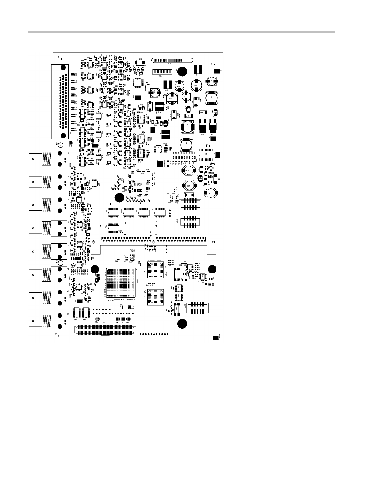
General Maintenance
Figure 4-2: Options AD and D DE Audio board, component side
4–24 WVR6020, WVR7020, and WVR7120 Waveform Rasterizers Service Manual
Page 63

General Maintenance
Figure 4 -3: Options AD and DDE Audio board back side indicator LED and test point locations
WVR6020, WVR7020, and WVR7120 Waveform Rasterizers Service Manual 4–25
Page 64

General Maintenance
Figure 4-4: F
ront panel board indicator LED locations (viewed from back side)
4–26 WVR6020, WVR7020, and WVR7120 Waveform Rasterizers Service Manual
Page 65

Repackaging Instructions
This section contains the information needed to repackage the waveform rasterizer
for shipment or storage.
Packaging
When repacking the instrument for shipment, use the original packaging. If
the packagi
representative to obtain new packaging. Refer to Contacting Tektronix, following
the copyright statement, for the mailing address, the email address, and phone
number.
Seal the shipping carton with an industrial stapler or strapping tape.
Shipping to the Service Center
ng is unavailable or unfit for use, contact your local Tektronix
Repackaging Instructions
Contact the Service Center to get an RMA (Return Material Authorization)
number, and any return or shipping information you may need.
If the instrument is being shipped to a Tektronix Service Center, enclose the
following information:
The RMA number.
The owner’s address.
and phone number of a contact person.
Name
Type and serial number of the instrument.
Reason for returning.
A complete description of the service required.
Mark the address of the Tektronix Service Center and the return address on the
shipping carton in two prominent locations.
WVR6020, WVR7020, and WVR7120 Waveform Rasterizers Service Manual 4–27
Page 66

Repackaging Instructions
4–28 WVR6020, WVR7020, and WVR7120 Waveform Rasterizers Service Manual
Page 67

Replaceable Mechanical Parts
Page 68

Page 69

Replaceable Parts
This section contains a list of the replaceable modules and replaceable parts for
the WVR6020, WVR7020, and WVR7120 Waveform Rasterizers. Use this list
to identify and order replacement parts. Note that not all parts listed in this
section are present on every model. The parts present will depend on the model
and options
Parts Ordering Information
installed.
Module Servicing
Replaceme
representative.
Changes t
components as they become available and to give you the benefit of the latest
improvements. Therefore, when ordering parts, it is important to include the
following information in your order:
Part number
Instrument type or model number
Instr
Instrument modification number, if applicable
If you order a part that has been replaced with a different or improved part, your
local Tektronix field office or representative will contact you concerning any
chan
Modules can be serviced by selecting one of the following three options. Contact
your local Tektronix service center or representative for repair assistance.
Module Exchange. In some cases you may exchange your module for a
remanufactured module. These modules cost significantly less than new modules
and meet the same factory specifications. For more information about the module
exchange program, call 1-800-833-9200. Outside North America, contact a
Tektronix sales office or distributor; see the Tektronix Web site for a list of offices:
www.tektronix.com.
nt parts are available through your local Tektronix field office or
o Tektronix products are sometimes made to accommodate improved
ument serial number
ge in part number.
Module Repair and Return. You may ship your module to us for repair, after
which we will return it to you.
New Modules. You may purchase replacement modules in the same way as other
replacement parts.
WVR6020, WVR7020, and WVR7120 Waveform Rasterizers Service Manual 5–1
Page 70

Replaceable Parts
Using the Replaceable Parts Lists
Use this list to identify and order replacement parts. The following table describes
each column in the parts list.
Column Column name Description
1
2Tektronixp
3and4
5
6
Figure & index number Items in this section are referenced by figure and index numbers to the
art number
Serial numb
Qty This indicates the quantity of parts used.
Name & des
er
cription
exploded view illustrations that follow.
Use this part number when ordering replacement parts from Tektronix.
Column thre
Column four indicates the serial number at which the part was discontinued.
No entry indicates the part is good for all serial numbers.
An item na
space limitations, an item name may sometimes appear as incomplete. Use
the U.S. Federal Catalog handbook H6-1 for further item name identification.
me is separated from the description by a colon (:). Because of
e indicates the serial number at which the part was first effective.
Abbreviations
Abbreviations conform to American National Standard ANSI Y1.1-1972.
5–2 WVR6020, WVR7020, and WVR7120 Waveform Rasterizers Service Manual
Page 71

Replaceable Parts
Fig. & index
number
5-1
-1 211-0734-00 16
-2 200-4873-00 1
-3
-4 146-0116-00 1
-5
-6 131-5450-00
-7
-8 131-4131-00 1
-9 211-0410-00 2
-10 119-7086-00 1
-11 351-
-12 212-0158-00 8
-13 351-0751-01 1
-14 211-0721-00 4
-15 119
-16 311-2570-00 3
-17 210-1039-00 6
-18 671-5382-01 1
19
-
-20 260-2774-01 1
-21 354-0025-00 1
-22 213-0216-00 1
-23 367-0530-00 2
Tektronix part
number
671-6282-00 1
671-6249-00 1
671-6043-02 1
671-6100-02 1
131-4046-00
214-3903-00
0104-03
-6801-00
66-0816-01
3
Serial no.
effective
Serial no.
discont’d Qty Name & descript
CIRCUIT BOARDS AND CHASSIS
SCREW,MACHINE; 6-32 X 0.25O,FLH100,STL,CDPL,T-10 TORX DR
COVER; TOP,ST
CIRCUIT BD ASSY; DUAL MAIN NO
COMPOSITE,3
CKT BD SUBASSY; DUAL MAIN WITH COMPOSITE, 389378900,
WIRED,UNTE
CIRCUIT BD ASSY; MAIN,NO COMPOSITE,389-3789-00 WIRED,TESTED
(WVR6020 ON
CIRCUIT BD ASSY; MAIN WITH COMPOSITE,389-3789-00 WIRED,TESTED
(WVR6020 O
BATTERY, DRY; 3.0V,850MAH,LITHIUM,0.57X1 INCHES;CR4250SE,SAFETY
CONTROLL
-
-
6* SCREW,J
1
1
3
CONN,DSUB; PCB/PNL,FEMALE,RTANG,15 POS,0.318 MLG X 0.125
TAIL,4-4
CONN,DSUB; PCB,HIGH DENSITY;FEMALE,RTANG,15 POS,0.078
CTR,0.3
GOLD,SAFETY CONTROLLED
THD, X 0.312 THD EXT 4-40
CONN,P
CONTROLLED
SCR,AS
FILTER,EMI; AC LINE CONNECTOR/INPUT
R;6.0A,120-250VAC,DC-400 HZ,2.2 NF CY,100 NF CX,IEC
FILTE
INPUT,FAST-ON/SOLDER LUG OUTPUT,CHASSIS MOUNT,SAFETY
CONTROLLED;FN9222-6/06
SL SECT,DWR EXT; 12.625 L,W/O HARDWARE SAFETY CONTROLLED
W,MACHINE; 8-32 X 0.375,PNH,STL,CDPL,T-20 TORX DR
SCRE
TRK,SL OUT SECT; STATIONARY & INTERMEDIATE SAFETY
TROLLED
CON
SCREW,MACHINE; 6-32 X 0.375,PNH,STL,CDPL,T-15 TORX DR
POWER SUPPLY; 110W,AC-DC,5VDC 22A OUT,90-264VAC 47-63HZ
IN,PFC,75% EFF,OPEN FRAME,6.5 X 3 X 1.26 IN,UL,CSA,VDE,SAFETY
NTROLLED
CO
ENCODER; DIGITAL CONTACTING ENCODER; PCB MOUNT, .354 DIA
LE,1.0 L X .25 DIA SHAFT, NO DETENTS, 36 COUNTS PER TURN.
HO
ECW1J-B32-SEO/058
ASHER,LOCK; 0.521 ID,INT,0.025 THK,SST
W
CIRCUIT BD ASSY; FRONT PANEL,TESTED,389-3257-00 WIRED
KNOB; SILVER GRAY, 0.420OD, 0.520H, PC/ABS BAYBLEND FR110,FRONT
PAN EL
SWITCH,KEYPAD; ELASTOMERIC,FRONT PANEL,PUSHBUTTON
RING,RETAINING; EXTERNAL,U/O 0.187 DIA SFT
THUMBSCREW; 10-32 X 0.85,0.375 OD HD,SST W/SLOT
HANDLE,BOW; AL,1.0 X 1.25,STAIN FINISH,SAFETY CONTROLLED
ion
ANDARD INSTRUMENT,0.050 AL,SAFETY CONTROLLED
89-3789-00 WIRED,TESTED (WVR7020, WVR7120 O NLY)
STED (WVR7020, WVR7120 ONLY)
LY)
NLY)
ED
0 THD INSERTS,BD RETENTION
50 MLG X 0.125 TAIL,4-40 THD INSERT,BD RETENTION,30
ACK; 4-40 X 0.312 LONG,0.188 H HEX HEAD STAND OFF,4-40 INT
LUG,ELEC; MALE W/LOCKING ADPTR,EXT MTG,SAFETY
SEM WSHR; 4-40 X 0.437,PNH,STL,CDPL,T-10 TORX DR
WVR6020, WVR7020, and WVR7120 Waveform Rasterizers Service Manual 5–3
Page 72

Replaceable Parts
Fig. & index
number
-24
-25 101-0160-01 1
-26 441-2295-0
-27 210-0457-00
-28 150-5009-00 1
-29 211-0410-00 6
-30 150-0277
-31 441-236
-32 211 -072
-33 337-4309-00 1
-34 211-1161-00 8
-35 119-70
-36 407-5
-37 671-9935-01 1
-38 131-m057-00 1
-39 131-
-40 374-
1
Quantity varies with instrument and audio option.
Tektronix part
number
335-1835-00 1
335-1836-00 1
335-1837-00 1
335-1838-00 1
335-1839-00 1
335-1840-00 1
0
-00
2-00
2-00
36-00
010-00
3925-00
4371-00
Serial no.
effective
Serial no.
discont’d Qty Name & descript
ion
MARKER,IDENT, FRONT PANEL ID W/O COMPOSITE, W/EYE, WVR7120
MARKER,IDENT, FRONT PANEL ID W/ COMPOSITE, W/EYE,WVR7120
MARKER,IDENT
MARKER,IDENT, FRONT PANEL ID W/ COMPOSITE, W/EYE,WVR7020
MARKER,IDENT, FRONT PANEL ID W/O COMPOSITE, WVR6020
MARKER,IDE
TRIM RING; FRONT,19.000 X 1.718 X 0.345,PC/ABS
1
7
1
46
1
15
2
1
1
1
CHASSIS,FRONT; 0.050 AL,SAFETY CONTROLLED
NUT,PL,AS
DIODE,OPTO; LED;HI-EFFIC RED,626NM,3.4MCD AT
10MA;HLMP
SCR,ASSEM WSHR; 4-40 X 0.437,PNH,STL,CDPL,T-10 TORX DR
LT EMITTING DIODE; GREEN, 570 NM, 1206, REVERSE MOUNT;
APTD3216MGCK-01
CHASSIS,MAIN; STANDARD
INSTRUMENT,0.050 AL,W/HARDWARE,SAFETY CONTROLLED
SCREW,MACHINE; 6-32 X 0.250,PNH,STL,CDPL,T-15 TORX DR
SHIELD
SCREW,MACHINE; 4-40 X 1.500,PAN HEAD,T-10 TORX,ZINC PL
FAN ASSEMBLY; DC,12V;0.105A,8.6 CFM,30DBA,3 LEAD, TACH OUTPUT,
WITH CONN & HOUSING,SAFETY CONTROLLED
BRACKET ASSY,FAN; 0.050 AL,SAFETY CONTROLLED
CIRCU
CONN,RF:PCB,FEMALE,BNC,75OHM,EDGE LAUNCH TYPE
CONN,DSUB; PCB,FEMALE,RTANG,9 POS,0.112 CTR,0.318 MLG X 0.125
TAIL,4-40 THD INSERT,BD RETENTION,30 GOLD
SHIELD; POWER SUPPLY BOTTOM, 0.030 POLYCARBONATE, SAFETY
CONTROLLED
, FRONT PANEL ID W/O COMPOSITE, W/EYE,WVR7020
NT, FRONT PANEL ID WITH COMPOSITE, WVR6020
SEM WA; 6-32 X 0.312,STL CD PL,W/LOCKWASHER
-6305-021, YOKE LEAD BEND, 12MM T&R
; POWER SUPPLY,0.020 POLYCARBONATE,SAFETY CONTROLLED
IT BD ASSY; LOOP THROUGH,,389-3568-00,WIRED
5–4 WVR6020, WVR7020, and WVR7120 Waveform Rasterizers Service Manual
Page 73

Replaceable Parts
Figure 5-1: Replaceable parts, circuit boards and chassis
WVR6020, WVR7020, and WVR7120 Waveform Rasterizers Service Manual 5–5
Page 74

Replaceable Parts
Fig. &
index
number
5-2
-1 174-5224-00 1
-2 174-4769-00 1
-3 260-5012-00 1
-4 134-0246-00 12
-5
-6 210-1039-00 10
-7
-8 119-5067-00 4
-9 131-7257-00 1
-10 260-5015-00 1
-11 131-3572-00 1
-12 260-5000-00 1
-13 150-1022-00 1
-14 1
-15 131-6187-00 1
-16 131-7244-00 2
-17 131-5457-00 3
-18 174-4771-00 1
-19 200-4800-00 1
-20 210-0457-00
-21 211-0410-00
1
Quantity varies with instrument m odel.
Tektronix part
number
131-7270-00 10
220-0497-00 10
Serial no.
effective
Serial no.
discont’d Qty Name & description
CABLES, CONNECTORS, ETC.
CA ASSY,SP; PWR,BR;10.250 L;18 AWG;CONN HDR 1 X 8 AND CONN
HDR 1 X12 AND 1X2;PWR SUPPLY TO MAIN BD AND EYE BDS
CA ASSY,SP; HV,BR,15.00 L & 4.00 L;CONN EACH END;LINE FILTER
TO PWR SUPPLY,SAFETY CONTROLLED
SWITCH,DIP; SPST,SLIDE,DIP,4 POSITION,GOLD OVER NICKEL,0.4VA
@ 20VDC,0.05 HALF PITCH;TD04H0SK1,SMD
1
PLUG,HOLE COVER; BUTTON PLUG,;0.578 HEAD DIA X 0.406
THK,ACCOM 0.5 DIA HOLE,0.015-0.125 THK PNL,NYLON,BLACK
1
CONN,RF PLUG; BNC,PCB,PNL MNT,FEMALE,RTANG,75 OHM, 0.510
H X 0.169 TAIL,LOW PROFILE ZINC DIE CAST HOUSING
1
WASHER,LOCK; 0.521 ID,INT,0.025 THK,SST
1
NUT,PLAIN,HEX; 0.5-28 X 0.562 HEX,BRS CD PL
FILTER,RFI; EMI, COMMON MODE CHOKE COIL; 2LINES, 200 0HM
IMP, 20- 300MHZ, 50V, 0.5A; 8 PIN SMD; ZJYS51R5-4P
CONN,JACK; PCB/PNL,RJ45,CAT5,W/LEDS YELLOW &
GREEN,FEMALE,RTANG,8 POS,0.1 CTR,0.528 H X 0.138 TAIL,10/100
BASE TX AND RX MAGNETICS MODULE,SAFETY CONTROLLED
SWITCH,PUSH; SPST,TACT;50MA,50V,MOMENTARY,SILVER
CONTACTS;KSC221G,GULLWING SMD,T&R
CONN,HDR:; PCB,;MALE,STR,2 X 7,0.1 CTR,0.385 H X 0.120
TAIL,SHRD/4 SIDES,CTR PLZ,30 GOLD,0.150 END DIM;,,
SWITCH,SLIDE; SPST;DIP8 POSITION,GOLD OVER
NICkEL,3A,2PF,SEALED;90HBW08S
DISPLAY,OPTO; ,LED;RED,660NM,7SEG,0.3 INCH DISPLAY,125UCD
PER SEGMENT AT10MA,COMMON ANODE,LEFT HAND
DECIMAL;MAN72A
FUSE; UL/IEC127, F3.15A H, 250VAC (5 x 20 m m)
CONN,HDR PWR; PCB,MALE,STR,1 X 8,0.156 CTR,0.450 MLG X 0.125
TAIL,PLZ WALL,TIN,SAFETY CONTROLLED
CONN,HDR; SMD,MALE,STR,2 X 5,0.100 CTR,0.350 H,0.165
MLG,SHRD/4 SIDES,MIL PLZ,30 GOLD,SAFETY CONTROLLED (ONE
ON MAIN BOARD, ONE ON FRONT PANEL)
CONN,HDR; PCB,;MALE,STR,1 X 3,0.10 CTR,0.535 H X 0.130
TAIL,SHRD/4 SIDES,CTR PLZ,LATCHING,BD RETENTION,30 GOLD,
CA ASSY,SP; IDC,RIBBON,10.00 L,DOUBLE ENDED,FEMALE,2 X 5
POS;F/P BD TO MAIN BD,SAFETY CONTROLLED
COVER,MINI; 2X FEX-440,SAFETY CONTROLLED
NUT,PL,ASSEM WA; 6-32 X 0.312,STL CD PL,W/LOCKWASHER
SCR,ASSEM WSHR; 4-40 X 0.437,PNH,STL,CDPL,T-10 TORX DR
5–6 WVR6020, WVR7020, and WVR7120 Waveform Rasterizers Service Manual
Page 75

Replaceable Parts
Figure 5-2: WVR6020, WVR7020, and WVR7120 replaceable cables, connectors, and other mechanical parts
WVR6020, WVR7020, and WVR7120 Waveform Rasterizers Service Manual 5–7
Page 76

Replaceable Parts
Fig. &
index
number
5-3
-1 119-5067-00 4
-2 131-7257-00 1
-3 260-5015-00 1
-4 131-5457-00 3
-5
-6 146-0116-00 1
-7
-8 159-5010-00 2
-9 159-5022-00 3
-10 131-7244-00 3
-11 159-5003-00 1
-12 159-5008-00 2
Tektronix part
number
150-5037-00 1
260-5000-00 1
Serial no.
effective
Serial no.
discont’d Qty Name & description
MAIN BOARD
FILTER,RFI; EMI,COMMON MODE CHOKE COIL;2LINES,200 0HM
IMP,20- 300MHZ,50V,0.5A;8 PIN SMD;ZJYS51R5-4P
CONN,JACK; PCB/PNL,RJ45,CAT5,W/LEDS YELLOW &
GREEN,FEMALE,RTANG,8 POS,0.1 CTR,0.528 H X 0.138 TAIL,10/100
BASE TX AND RX MAGNETICS MODULE,SAFETY CONTROLLED
SWITCH,PUSH; SPST,TACT;50MA,50V,MOMENTARY,SILVER
CONTACTS;KSC221G,GULLWING SMD,T&R
CONN,HDR; PCB,MALE,STR,1 X 3,0.10 CTR,0.535 H X 0.130
TAIL,SHRD/4 SIDES,CTR PLZ,LATCHING,BD RETENTION,30 GOLD,
SAFETY CONTROLLED
DIODE,OPTO; LED;GREEN,571NM,4.0 TO 9.0 MCD AT 20MA,155 DEG
VIEW ANGLE,TINTED,DIFFUSED;HSMG-C170,SMD,0805,8MM T&R
BATTERY,DRY; 3.0V,850MAH,LITHIUM,0.57 X1.0;CR4250SE,SAFETY
CONTROLLED
SWITCH,SLIDE; SPST;DIP8 POSITION,GOLD OVER
NICKEL,3A,2PF,SEALED;90HBW08S,44MM T&R
FUSE,SMD; 7A,125V,FAST BLOW,0.1 X 0.1X 0.24;UL REG,CSA
CERT,SAFETY CONTROLLED
FUSE; 5.0A,125V;FAST BLOW,0.1 X 0.1 X 0.24,UL REG,CSA
CERT;451005,SAFETY CONTROLLED
CONN,HDR; SMD,MALE,STR,2 X 5,0.100 CTR,0.350 H,0.165
MLG,SHRD/4 SIDES,MIL PLZ,30 GOLD,SAFETY CONTROLLED
FUSE,THRM,CHIP; SELF RESETTING FUSE,1.1A HOLD,2.2A TRIP AT
20 DEG C,30V MAX,SAFETY CONTROLLED (MAIN)
FUSE,THRM,CHIP; SELF RESETTING FUSE,1.5A HOLD,3.0A TRIP AT
20 DEG C,30V MAX,SAFETY CONTROLLED (MAIN)
5–8 WVR6020, WVR7020, and WVR7120 Waveform Rasterizers Service Manual
Page 77

Replaceable Parts
Figure 5-3: Main board replaceable components and connectors, WVR7020, WVR7120, and WVR6020
WVR6020, WVR7020, and WVR7120 Waveform Rasterizers Service Manual 5–9
Page 78

Replaceable Parts
Fig. &
index
number
5-4
-1 671-9938-02 1
-2 131-7270-00 8
-3 220-0497-00 8
-4 210-1039-00 8
-5
-6 131-7575-00 1
-7
-8 664-6099-00 1
-8 664-9936-00 1
-9 174-5301-00 2
-10 119-7167-00 1
-11 129-1570-00 3
-12 131-7430-00 1
-13 214-3903-00 2
not shown 174-4281-00 2
not shown 200-4800-00 1
not shown 174-4586-00 1
Tektronix part
number
174-4973-00 1
129-0208-00
Serial no.
effective
Serial no.
discont’d Qty Name & description
OPTIONS EYE/PHY AND AUDIO - BOARDS AND CONNECTORS
CIRCUIT BD ASSY; DIGITAL ANALOG AUDIO,
389-3575-00 WIRED,TESTED WVR6020 & WVR7120 AUDIO
OPTIONS ONLY.
CONN,RF,PLUG; BNC,PCB,PNL MNT,FEMALE,RTANG,75 OHM, 0.510
H X 0.169 TAIL,LOW PROFILE ZINC DIE CAST HOUSING
NUT,PLAIN,HEX; 0.5-28 X 0.562 HEX,BRS CD PL
WASHER,LOCK; 0.521 ID,INT,0.025 THK,SST
WVR6020 & WVR7120 OPTIONS AD & DDE ONLY. CABLE ASSY; 80
POS. CABLE WITH TWO 2X40 CONNECTORS
CONN,HDR; SMD,SYS50;MALE,STR,2 X 40,0.05 X 0.1
CTR,0.480H,SHRD/4,CTR PLZ,LATCHING,30 GOLD,SAFETY
CONTROLLED
5
SPACER,POST; 0.312 L,6-32 STUD,BRS,ELECTROLESS NICKEL,0.25
HEX (OPTIONS EYE AND PHY ONLY)
CIRCUIT BD.SUB ASSY; SD, EYE BOARD,FUNCTIONAL BD.TEST
LEVEL 389-3569-00, WIRED (WVR6020, OPTIONS EYE AND PHY
ONLY )
CIRCUIT BD.SUB ASSY; HD/SD EYE BOARD,FUNCT BD.TEST LEVEL,
389-3569-00 WIRED (WVR7120, OPTIONS EYE AND PHY ONLY)
CABLE ASSY ELEC: RF,50 OHM COAX, SMA/PLUG/ST (OPTIONS EYE
AND PHY ONLY)
WVR6020 & WVR7120 OPTION DDE ONLY. CIRCUIT BD ASSY; CAT552
DOLBY E/DIGITAL DECODER MODULE; 72 PIN SIMM; SAFETY
CONTROLLED
POST,SPACER; 1.385 X 0.250 X 0.375 DEEP
WVR6020 & WVR7120 OPTIONS AD & DDE ONLY.. CONN,DSUB; SLDR
CUP,MALE,STR,62 POS,0.100 CTR,30 GOLD
SCREW,JACK; 4-40 X 0.312 LONG,0.188 H HEX HEAD STAND OFF,4-40
INT THD, X 0.312 THD EXT 4-40
CA ASSY.SP; FLAT RIBBON,IDC,30 AWG,6.100L,40
POS,-DUBLIN,SAFETY CONTROLLED
COVER,MINI; 2X FEX-440,SAFETY CONTROLLED
CA ASSY; RIBBON,2.0 L,DOUBLE ENDED,IDC,FEMALE,2 X 20,0.050
CTR,PLZ
5–10 WVR6020, WVR7020, and WVR7120 Waveform Rasterizers Service Manual
Page 79

Replaceable Parts
Figure 5-4: Option EYE/PHY and Audio Options boards and connectors
WVR6020, WVR7020, and WVR7120 Waveform Rasterizers Service Manual 5–11
Page 80

Replaceable Parts
Fig. &
index
number
5-5
-1 276-5012-00
-2 131-7272-00 1
-3 136-1435-00 1
-4 131-7575-00 1
*
Count vari
Tektronix part
number
es with option
Serial no.
effective
Serial no.
discont’d Qty Name & description
AUDIO BOARD - FRONT
* PB-FREE;EMI SUPPRESSION; FERRITE BEAD;120 OHMS@100MHZ,
IMAX=200MA, DCR<0.2 OHM;BLM11A121SPT, 0603, 7 INCH T&R
CONN, DSUB; PCB/PNL, FEMALE, 62 POS, RTANG, 0.100 CTR, 0.495
H X 0.125 TAIL, 30 GOLD, 4-40 THD INSERTS, BOARD RETENTION,
HIGH DENSITY CONN
SOCKET, SIMM; PCB, FEMALE, RTANG, 1 X 72, 0.05 CTR, 0.448 H X
0.11 TAIL, LEFT POLARIZED, 30 GOLD
CONN, HDR; SMD, SYS50;MALE, STR, 2 X 40, 0.05 X 0.1 CTR, 0.480H,
SHRD/4, CTR PLZ, LATCHING, 30 GOLD, SAFETY CONTROLLED
5–12 WVR6020, WVR7020, and WVR7120 Waveform Rasterizers Service Manual
Page 81

Replaceable Parts
Figure 5-5: Audio board component-side components, Options AD and DDE
WVR6020, WVR7020, and WVR7120 Waveform Rasterizers Service Manual 5–13
Page 82

Replaceable Parts
Fig. &
index
number
5-6
-1 276-5012-00 20
Tektronix part
number
Serial no.
effective
Serial no.
discont’d Qty Name & description
AUDIO BOARD - BACK
PB-FREE; EMI SUPPRESSION; FERRITE BEAD;120 OHMS@100MHZ,
IMAX=200MA, DCR<0.2 OHM;BLM11A121SPT, 0603, 7 INCH T&R
5–14 WVR6020, WVR7020, and WVR7120 Waveform Rasterizers Service Manual
Page 83

Replaceable Parts
Figure 5-6: Audio board back-side components, Options AD and DDE
WVR6020, WVR7020, and WVR7120 Waveform Rasterizers Service Manual 5–15
Page 84

Replaceable Parts
Fig. &
index
number
5-7
-1 200-4874-00 1
-2 131-3295-00 1
-3
-4 214-3903-00
-5
-6 441-2295-00 1
-7
Tektronix part
number
389-3574-00 1
671-9937-00 1
211-0721-00
441-2361-00 1
Serial no.
effective
Serial no.
discont’d Qty Name & description
WVRRFP
COVER; TOP TO REMOTE FRONT PANEL,0.050 AL,SAFETY
CONTROLLED
CONN,RCPT,ELEC; HEADER,2 X 25,0.1 SPACING
CIRCUIT BOARD; FRONT PANEL REGULATOR,SAFETY CONTROLLED
CIRCUIT BD ASSY; FRONT PANEL
REGULATOR,389-3574-00 WIRED,TESTED
-
-
SCREW,JACK; 4-40 X 0.312 LONG,0.188 H HEX HEAD STAND OFF,4-40
INT THD, X 0.312 THD EXT 4-40
SCREW,MACHINE; 6-32 X 0.375,PNH,STL,CDPL,T-15 TORX DR
CHASSIS,FRONT; REMOTE FRONT PANEL,0.050 AL
CHASSIS,MAIN; REMOTE FRONT
PANEL,,0.050 AL,W/HARDWARE,SAFETY CONTROLLED
5–16 WVR6020, WVR7020, and WVR7120 Waveform Rasterizers Service Manual
Page 85

Replaceable Parts
Figure 5-7: WVRRFP
WVR6020, WVR7020, and WVR7120 Waveform Rasterizers Service Manual 5–17
Page 86

Replaceable Parts
Fig. &
index
number
5-8
-1 012-1688-00 1
-2 200-4804-00 1
-3 131-0422-00 1
Tektronix part
number
Serial no.
effective
Serial no.
discont’d Qty Name & description
ANALOG AUDIO BREAKOUT CABLE - OPTIONAL ACCESSORY
WVR7020, WVR7120 AND WVR6020 WITH OPTIONS AD AND DDE
ONLY. CABLE ASSEMBLY; ANALOG/AUDIO BREAKOUT
COVER; SHIELD,ELEC CONN,37 POS DSUB,ZINC
CONN,DSUB; SLDR CUP/PNL,;MALE,STR,37 POS,0.112 CTR,0.186 H X
0.126 TAIL,0.125 DIA THRU MTG
Figure 5-8: Analog audio breakout cable assembly
5–18 WVR6020, WVR7020, and WVR7120 Waveform Rasterizers Service Manual
Page 87

Replaceable Parts
Fig. & index
number
Tektronix part
number
071-2231-xx 1
071-2232-xx 1
071-2233-xx 1
071-2238-x
063-4056-xx 1
See Description
x
Serial no.
effective
Serial no.
discont’d Qty Name & descript
ion
STANDARD ACCESSORIES
MANUAL, TECH;QUICK START USER MANUAL, ENGLISH,
WVR6020/WVR7020/WVR7120 (OPTION L0 ONLY)
MANUAL, TECH;QUICK START USER MANUAL, JAPANESE,
WVR6020/WVR7020/WVR7120 (OPTION L5 ONLY)
MANUAL, TECH;QUICK START USER MANUAL, SIMPLIFIED CHINESE,
WVR6020/WVR7020/WVR7120 (OPTION L7 ONLY)
1
1
MANUAL, TECH;RELEASE NOTES, WVR6020/WVR7020/WVR7120
DOCUMENTAT
CABLE ASSY, POWER:
ION;PRODUCT CD, ENGLISH, WVR6020/WVR7020/WVR7120
OPTION COUNTRY P/N
A0
A1
A2
A3
A4
A5
A6
A10
N. AMERICA
UNIV EURO
UK
AUSTRALIA
USA 240V
LAND
SWITZER
JAPAN
CHINA
-00
161-0066
161-0066-09
161-0066-10
6-13
161-006
161-0066-12
161-0154-00
08-00
161-A0
161-0304-00
WVR6020, WVR7020, and WVR7120 Waveform Rasterizers Service Manual 5–19
 Loading...