


xx
WVR720UP, WVR820UP, and WVR830UP Upgrades
for the WVR7200, WVR8200, and WVR8300
ZZZ
Waveform Rasterizers
Instructions
Warning
The servicing instructions ar
only. To avoid personal injury, do not perform any servicing
unless you are qualified to do s
prior to performing service.
e for use by qualified personnel
o. Refer to all safety summaries
www.tektronix.com
P075101603*
*
075-1016-03

Copyright © Tektronix. All rights reserved. Licensed software products are owned by Tektronix or its subsidiaries
or suppliers, and are protected by national copyright laws and international treaty provisions.
Tektronix products are covered by U.S. and foreign patents, issued and pending. Information in this publication
supersedes that in all previously published material. Specifications and price change privileges reserved.
TEKTRONIX and TEK are registered trademarks of Tektronix, Inc.
Contacting Tektronix
Tektronix, Inc.
14150 SW Karl Braun Drive
P.O . B ox 5 0 0
Beaverto
USA
For product information, sales, service, and technical support:
n, OR 97077
In North America, call 1-800-833-9200.
World wide, vis i t www.tektronix.com to find contacts in your area.

Table of Contents
Important safety information ................. ................................ ................................ ..... 1
General safety summary ...................................................................................... 1
Service safety summary .......................... ................................ ............................. 3
Terms in thi
Symbols and terms on the product........................................................................... 4
Kit description ............... ................................ .................................. ..................... 5
Products.......... ................................ ................................ ............................... 7
Required tools.................................................................................................. 7
Kit parts lists ...... .................................. ................................ ........................... 8
Upgrade
Ver i
installation............. ................................ ................................ .................. 12
Verify the currently installed options....................................................................... 12
How to prevent electrostatic discharge..................................................................... 13
Install software upgrade........................................ ................................ .............. 14
Install the option hardware... ................................ .................................. .............. 18
Install the option software key ................ .................................. ............................ 35
fy the upgrade ....... ................................ ................................ .......................... 36
Quick verification............................... ................................ .............................. 36
Detailed verification .......................................................................................... 36
s manual ... .................................. ................................ ..................... 4
WVR720UP, WVR820UP, and WVR830UP Upgrades i

Table of Contents
ii WVR720UP, WVR820UP, and WVR830UP Upgrades

Important safety information
This manual contains information and warnings that must be followed by the user
for safe operation and to keep the product in a safe condition.
To safely perform service on this product, additional information is provided at
the end of this section. (See page 3, Service safety summary.)
General safety summary
Use the product only as specified. Review the following safety precautions to
avoid inj
Carefully read all instructions. Retain these instructions for future reference.
ury and prevent damage to this product or any products connected to it.
Comply wi
For correct and safe operation of the product, it is essential that you follow
general
in this manual.
The pro
Only qualified personnel who are aware of the hazards involved should remove
the co
Before use, always check the product with a known source to be sure it is
oper
This product is not intended for detection of hazardous voltages.
Use personal protective equipment to prevent shock and arc blast injury where
hazardous live conductors are exposed.
While using this product, you may need to access other parts of a larger system.
Read the safety sections of the other component manuals for warnings and
autions related to operating the system.
c
When incorporating this equipment into a system, the safety of that system is the
esponsibility of the assembler of the system.
r
th local and national safety codes.
ly accepted safety procedures in addition to the safety precautions specified
duct is designed to be used by trained personnel only.
ver for repair, maintenance, or adjustment.
ating correctly.
WVR720UP, WVR820UP, and WVR830UP Upgrades 1

Important safety information
To avoid fire or
personal
injury
Use proper powe
certified for the country of use.
Do not use the provided power cord for other products.
Ground the product. This product is grounded through the grounding conductor
of the power cord. To avoid electric shock, the grounding conductor must be
connected to earth ground. Before making connections to the input or output
terminals of the product, make sure that the product is properly grounded.
Power disconnect. The power cord disconnects the product from the power
source. See instructions for the location. Do not position the equipment so that
it is difficult to operate the power cord; it must remain accessible to the user at
all times to allow for quick disconnection if needed.
Observe all terminal ratings. To a v oi d fire or shock hazard, observe all ratings
and markings on the product. Consult the product manual for further ratings
information before making connections to the product.
Do not apply a potential to any terminal, including the common terminal, that
exceeds the maximum rating of that terminal.
Do not operate without covers. Do not operate this product with covers or panels
removed, or with the case open. Hazardous voltage exposure is possible.
r cord. Use only the power cord specified for this product and
Avoid exposed circuitry. Do not touch exposed connections and components
when power is present.
Do not operate with suspected failures. If you suspect that there is damage to this
product, have it inspected by qualified service personnel.
Disable the product if it is damaged. Do not use the product if it is damaged
or operates incorrectly. If in doubt about safety of the product, turn it off and
disconnect the power cord. Clearly mark the product to prevent its further
operation.
Before use, inspect voltage probes, test leads, and accessories for mechanical
damage and replace when damaged. Do not use probes or test leads if they are
damaged, if there is exposed metal, or if a wear indicator shows.
Examine the exterior of the product before you use it. Look for cracks or missing
pieces.
Use only specified replacement parts.
Do not operate in wet/damp conditions. Be aware that condensation may occur if
a unit is moved from a cold to a warm environment.
Do not operate in an explosive atmosphere.
Keep product surfaces clean and dry. Remove the input signals before you clean
the product.
2 WVR720UP, WVR820UP, and WVR830UP Upgrades

Important safety information
Provide proper
details on installing the product so it has proper ventilation.
Slots and open
otherwise obstructed. Do not push objects into any of the openings.
Provide a safe working environment. Always place the product in a location
convenient for viewing the display and indicators.
Avoid improper or prolonged use of keyboards, pointers, and button pads.
Be sure your work area meets applicable ergonomic standards. Consult with an
ergonomics professional to avoid stress injuries.
Use care when lifting and carrying the product.
Use only the Tektronix rackmount hardware specified for this product.
Servicesafetysummary
The Service safety summary section contains additional information required to
safely perform service on the product. Only qualified personnel should perform
service procedures. Read this Service safety summary and the General safety
summary before performing any service procedures.
ventilation. Refer to the installation instructions in the manual for
ings are provided for ventilation and should never be covered or
oid electric shock. Do not touch exposed connections.
To av
Do not service alone. Do not perform internal service or adjustments of this
product unless another person capable of rendering first aid and resuscitation is
present.
sconnect power. To avoid electric shock, switch off the product power and
Di
disconnect the power cord from the mains power before removing any covers or
panels, or opening the case for servicing.
Use care when servicing with power on. Dangerous voltages or currents may exist
in this product. Disconnect power, remove battery (if applicable), and disconnect
test leads before removing protective panels, soldering, or replacing components.
Verify safety after repair. Always recheck ground continuity and mains dielectric
strength after performing a repair.
WVR720UP, WVR820UP, and WVR830UP Upgrades 3
Important safety information
Termsinthismanual
These terms may appear in this manual:
WARNING. Warning statements identify conditions or practices that could result
in injury or loss of life.
CAUTION. Caution statements identify conditions or practices that could result in
damage to this product or other property.
Symbols and terms on the product
These ter
The following symbol(s) may appear on the product:
ms may appear on the product:
DANGER indicates an injury hazard immediately accessible as you read
the mark
WARNING indicates an injury hazard not immediately accessible as you
read th
CAUTION indicates a hazard to property including the product.
ing.
e marking.
When this symbol is marked on the product, be sure to consult the manual
to find out the nature of the potential hazards and any actions which have to
betakentoavoidthem. (Thissymbolmayalsobeusedtorefertheuserto
ratings in the m anual.)
4 WVR720UP, WVR820UP, and WVR830UP Upgrades

Kit description
Kit description
This document provides instructions for installing the video, audio, and analysis
upgrades listed in the following tables into an existing Tektronix WVR7200,
WVR8200, or W
Table 1: Supported video upgrades
Video
upgrades WVR820UP WVR830UP WVR720UP Description
Option 2SDI Adds a second SDI input module, adding 2 additional SDI
Option 3G Adds support for 3G-SDI signal formats.
Option 4K Adds support for UHDTV1/4K signal formats.
Option CPS Adds support for Composite Analog Video Monitoring;
Option 3D Adds Stereoscopic 3-D Video Monitoring Capabilities
Option S3D Adds Stereoscopic 3-D Video Monitoring Capabilities
Option GEN Adds color bar and pathological signal generator for
Option AVD Add support for out-of-service audio/video delay
ion SIM
Opt
VR8300 waveform rasterizer.
inputs that support 3G-SDI, HD-SDI, and SD-SDI. (Option
3G is required for 3G-SDI support).
(requires Options 3G and 2SDI)
2 compos
option not compatible with Option 2SDI.
(including Simultaneous Input Monitoring (SIM) of dual
SDI inp
monitoring (SyncVu™)).
(including Simultaneous Input Monitoring (SIM) of dual
SDI in
monitoring (SyncVu™)).
SD/HD SDI. O ption 3G required for 3G-SDI support.
mea
Ad
or one HD/SD-SDI input and one CPS input; Option 3G
required for 3G-SDI formats support.
ite Analog inputs; passive loop-through. This
uts and synchronized left eye and right eye signals
puts and synchronized left eye and right eye signals
surement; requires Option AD or DPE.
ds simultaneous monitoring of 2 HD/SD-SDI inputs
WVR720UP, WVR820UP, and WVR830UP Upgrades 5

Kit description
Table 2: Suppor
Audio
upgrades WVR820UP WVR830UP WVR720UP Description
Option AD Adds Analog Audio Monitoring (2 sets of 6 channel Analog
Option DPE Adds Option AD capabilities (Analog and Digital Audio,
ted audio upgrades
Audio inputs and 8 channels of Analog Audio outputs); 16
channels Emb
(8 channels at a time).
Embedded or External AES), plus support for decoding
and monitor
Audio. (Audio cable available separately).
edded and AES/EBU Digital Audio support
ing Dolby E, Dolby D, and Dolby Digital Plus
Table 3: Supported analysis upgrades
Analysis
upgrades WVR820UP WVR830UP WVR720UP Description
Option EYE
Option PHY Adds Physical Layer Measurement Package (includes
Option PHY3 Adds Physical Layer Measurement Package (includes
Option PROD Adds Advanced Gamut Monitoring Package (Spearhead
Option DAT Adds data analysis capabilities. A llows for logic-level view
Adds Eye Pattern Display and Jitter Measurement
Package (includes 3G-SDI, HD-SDI, and SD-SDI
Eye pattern and Jitter waveform displays; automated
measurements of Eye pattern paramenters,Jitter, and
cable parameters; color bar and pathological signal
generation); Option 3G required for 3G-SDI support.
3G-SDI, HD-SDI, and SD-SDI Eye pattern and jitter
waveform displays; automated measurements of Eye
pattern parameters, jitter, and cable parameters; color bar
and pathological signal generation); Option 3G required
for 3G-SDI support.
3G-SDI, HD-SDI, and SD-SDI Eye pattern and jitter
waveform displays; automated measurements of Eye
pattern parameters, jitter, and cable parameters; Option
3G required for 3G-SDI support.
Display and Luma Qualified Vector Display).
of video and embedded audio data stream and ANC data
extraction.
6 WVR720UP, WVR820UP, and WVR830UP Upgrades

Products
Kit description
The following Tektronix products are supported by this kit:
WVR7200 (all instruments)
Required tools
WVR8200 (all
instruments)
WVR8300 (all instruments)
The following table lists the tools required to install the upgrade.
Table 4: Required tools
Name Description
TORX screwdriver handle (Hardware options
only)
T-10 and T-15 TORX tips (Hardware options
only)
ch socket (Hardware options only)
9/16 in
nch socket (Hardware options only)
3/16 i
ch socket (Hardware options only)
1/4 in
onitor
XGA M
dard PC
Stan
i-static wrist strap (Hardware options
Ant
only)
For WVR8000 Series upgrades, WVR8200
and WVR8300 Specifications and
rformance Verification manual and all
Pe
test equipment listed within to perform the
verification checks.
For W VR7200 upgrades, WVR7200
Specifications and Performance Verification
anual and all test equipment listed within to
m
perform the verification checks
Accepts TORX-driver bits
TORX-driver bit for T-10 and T-15 screw
heads
Deep so
Socke
Socke
Running Windows XP or Windows 7
Tek
Available for download from the Tektronix
Web site at www.tektronix.com/manuals.
Tektronix part number 077-0670-XX
Available for download from the Tektronix
W
cket to fit over BNC connector.
ttofit over audio connector posts.
ttofit over circuit board posts.
tronix part number 077-0260-XX.
eb site at www.tektronix.com/manuals
WVR720UP, WVR820UP, and WVR830UP Upgrades 7

Kit description
Kit parts lists
The following tables list the parts supplied with each upgrade kit. Before you
start the upgrade, verify that you received all of the parts for the upgrade kit you
ordered.
WVR820UP 2SDI
WVR830UP 2SDI
WVR720UP 2SDI
WVR820UP CPS
WVR830UP CPS
WVR720UP CPS
Table 5: Opt
Quantity Part number Description
1EA
1 EA 075-1016-XX
1 EA 870-0195
3 EA 211- 127
1 EA 335-2393-XX
ion 2SDI parts list
——
-XX
2-XX
ENVELOPE, IMPORTANT DOCUMENTS; CONTAINS
SOFTWARE OPTION KEY
INSTRUCTIONS; WVR720UP, WVR820UP, AND
WVR830UP
(this document)
CIRCUIT BOARD SUBASSY;WVR SDI,TESTED
SCREW, MACHINE; 6-32 X 0.250, PNH, STL, ZNPL,
T-15 TORX DR
LABEL REAR PANEL, SDI
UPGRADES
NOTE. Once the hardware is installed, you must download the software to
activate Option 2SDI. Go to www.tektronix.com/downloads. (See page 14, Install
software upgrade.)
e 6: Option CPS parts list
Tabl
Quantity Part number Description
1EA
1 EA 075-1016-XX
1 EA 870-0194-XX
3 EA 211-0722-XX
4 EA 220-0497-XX
4 EA 210-1039-XX
1 EA 335-2392-XX
——
ENVELOPE, IMPORTANT DOCUMENTS; CONTAINS
SOFTWARE OPTION KEY
INSTRUCTIONS; WVR720UP, WVR820UP, AND
R830UP UPGRADES
WV
IRCUIT BD SUBASSY; ANALOG COMPOSITE
C
CREW, MACHINE; 6-32 X 0.250, PNH, STEEL,
S
ZINC FINISH, T-15 TORX DR
NUT, PLAIN, HEX; .5-28 X .562 HEX, BRS, NI
(NICKEL) PLATED
WASHER, LOCK; 0.521 ID, INT, 0.025 THK, STEEL,
ZINC FINISH
LABEL REAR PANEL, COMPOSIT
8 WVR720UP, WVR820UP, and WVR830UP Upgrades

Kit description
WVR820UP EYE
WVR830UP PHY
WVR720UP PHY3
Table 7: Option
Quantity Part number Description
1EA
1 EA 075-1016-XX
1 EA 872-0189-XX
6 EA 211-0722-XX
4 EA 220-0497-
4 EA 210-1039-XX
1 EA 335-2394-XX
EYE parts list
——
XX
ENVELOPE, IMPO RTANT DOCUMENTS; CONTAINS
SOFTWARE OPTION KEY
INSTRUCTIONS; WVR720UP, WVR820UP, AND
WVR830UP UP
CIRCUIT BOA
SCREW, MAC
FINISH,T-15TORXDR
NUT, PLAIN, HEX; .5-28 X .562 HEX, BRS, NI
(NICKEL) PLATED
WASHER, LOCK; 0.521 ID, INT, 0.025 THK, STEEL,
ZINC FIN
LABEL RE
ISH
Table 8: Option PHY and PHY3 parts list
ity
Quant
1EA
1 EA 075-
1 EA 872-0189-XX
6 EA 211-0722-XX
4 EA 220-0497-XX
A
4E
1 EA 335-2394-XX
Part nu
——
1016-XX
0-1039-XX
21
mber
ption
Descri
OPE, IMPORTANT DOCUMENTS; CONTAINS
ENVEL
SOFTWARE OPTION KEY
INSTRUCTIONS; WVR720UP, WVR820UP, AND
WVR830UP UPGRADES
CIRCUIT BOARD SUBASSY; 3G-EYE
SCREW, MACHINE; 6-32 X 0.250, PNH, STEEL,
C FINISH, T-15 TORX DR
ZIN
T, PLAIN, HEX; .5-28 X .562 HEX, BRS, NI
NU
(NICKEL) PLATED
WASHER, LOCK; 0.521 ID, INT, 0.025 THK, STEEL,
ZINC FINISH
LABEL REAR PANEL, EYE, SDI CLOCK OUT
GRADES
RD SUBASSY; 3G-EYE
HINE; 6-32 X 0.250, PNH, STEEL, ZINC
AR PANEL, EYE, SDI CLOCK OUT
WVR720UP, WVR820UP, and WVR830UP Upgrades 9

Kit description
WVR820UP 3G
WVR830UP 3G
WVR720UP 3G
WVR820UP 4K
WVR830UP 4K
WVR820UP PROD
WVR830UP PROD
WVR720UP PROD
WVR820UP 3D
WVR720UP S3D
WVR720UP DAT
WVR720UP SIM
WVR720UP AVD
WVR720UP GEN
WVR820UP GEN
WVR820UP
AD
WVR830UP AD
WVR720UP AD
These are SW onl
y upgrades. No hardware is needed for these upgrades.
Table 9: SW option upgrades parts list
Quantity Part number Description
1EA
1 EA 075-1016-XX
——
ENVELOPE, IMPORTANT DOCUMENTS; CONTAINS
SOFTWARE OPTION KEY
INSTRUCTIONS; WVR720UP, WVR820UP, AND
WVR830UP UPGRADES
Table 10: Option AD parts list
Quantity Part number Description
1EA
1 EA 075-1016-XX
1 EA 671-9938-XX
3 EA 129-1570-XX
3 EA 211-0722-XX
8 EA 220-0497-XX
8 EA 210-1039-XX
1 EA 174-5696-XX
2 EA 214-3903-XX
1 EA 131-7430-XX
1 EA 200-4804-XX
——
ENVELOPE, IMPORTANT DOCUMENTS; CONTAINS
SOFTWARE OPTION KEY
INSTRUCTIONS; WVR720UP, WVR820UP AND
WVR830UP UPGRADES
CIRCUIT BD SUBASSY; DIGITAL AND ANALOG
AUDIO
POST, SPACER; 1.385 X 0.250 X 0.375 DEE P
SCREW, MACHINE; 6-32 X 0.250, PNH, STEEL,
ZINC FINISH, T-15 TORX DR
NUT, PLAIN, HEX; .5-28 X .562 HEX, BRS, NI
(NICKEL) PLATED
WASHER, LOCK; 0.521 ID, INT, 0.025 THK, STEEL,
ZINC FINISH
CABLE ASSEMBLY, 100 TO 80 POSITION, MAIN TO
AUDIO PCB
SCREW, JACK; 4-40 X 0.312 LONG, 0.188 H HEX
HEAD STAND OFF, 4-40 INT THD, X 0.312 THD EXT
4-40, STEEL, ZINC PLATED
CONN,DSUB; SLDR CUP,MALE,STR,62 POS ,0.100
CTR,30 GOLD
COVER; SHIELD,ELEC CONN,37 POS DSUB,ZINC
10 WVR720UP, WVR820UP, and WVR830UP Upgrades

Kit description
WVR820UP DPE
WVR830UP DPE
WVR720UP DPE
Table 11 : Optio
Quantity Part number Description
1EA
1 EA 075-1016-XX
1 EA 119-7167-XX
1 EA 119-7167-XX
3 EA 129-1570-XX
3 EA 211-0722-XX
8 EA 220-0497-XX
8 EA 210-10
1 EA 174-5696-XX
2 EA 214-3903-XX
1 EA 131-7430-XX
1 EA 200-4804-XX
n DPE parts list
——
39-XX
ENVELOPE, IMPORTANT DOCUME NTS; CONTAINS
SOFTWARE OPTION KEY
INSTRUCTIONS; WVR720UP, WVR820UP, AND
WVR830UP UP
CIRCUIT BD S
CIRCUIT BD
DECODER MODULE; 72 PIN SIMM; SAFETY
CONTROLLED
POST, SPACER; 1.385 X 0.250 X 0.375 DEEP
SCREW, MACHINE ; 6-32 X 0.250, PNH, STEEL,
ZINC FIN
NUT, PLA
(NICKEL) PLATED
WASHER, LOCK; 0.521 ID, INT, 0.025 THK, STEEL,
ZINC FINISH
CABLE ASSEMBLY, 100 TO 80 POSITION, MAIN TO
AUDIO
SCRE
HEAD STAND OFF, 4-40 INT THD, X 0.312 THD EXT
4-40, STEEL, ZINC PLATED
CONN,DSUB; SLDR CUP,MALE,STR,62 POS,0.100
CTR
COV
ISH, T-15 TORX DR
IN, HEX; .5-28 X .562 HEX, BRS, NI
PCB
W, JACK; 4-40 X 0.312 LONG , 0.188 H HEX
,30 GOLD
ER; SHIELD,ELEC CONN,37 POS DSUB,ZINC
GRADES
UB ASSY
ASSY; CAT552 DOLBY E/DIGITAL
WVR720UP, WVR820UP, and WVR830UP Upgrades 11

Upgrade installation
Upgrade installation
This section provides instructions for the following:
Verifying the currently installed options
Preventing ele ctrostatic discharge
Installing the software upgrade
Installing
Installing the software option key
thehardwareupgrade
Verify the currently installed options
The software option key supplied in this kit is based on the serial number you
supplie
option key enables the new option(s) you ordered and also preserves your
previously purchased options.
Before you install the upgrade, perform the following steps to verify which
options are currently installed in your instrument. After you install the upgrade,
you will verify that the new options are installed and that any previously installed
options are still enabled.
1. Power on the instrument you are upgrading.
2. Press the CONFIG button on the front panel.
3. Navigate to Utilities > View Instrument Options.
4. Mak
d when you ordered the upgrade for the instrument. The new software
e a list of the installed o ptions.
List installed options
12 WVR720UP, WVR820UP, and WVR830UP Upgrades

How to prevent electrostatic discharge
When you perform any service that requires internal access to the instrument,
adhere to the following precautions to avoid damage due to electrostatic discharge
(ESD):
1. Minimize handling of static-sensitive circuit boards and components.
2. Transport and store static-sensitive boards or modules in static protected
containers.
3. Discharge the static voltage from your body by wearing a grounded antistatic
wrist strap while handling these modules.
4. Service static-sensitive m odules only at a static-free work station.
5. Do not allow anything capable of generating or holding a static charge on
the work surface.
6. Handle circuit boards by the edges or hold onto grounded shields when
possible.
7. Do not slide circuit boards over any surface.
Upgrade installation
WVR720UP, WVR820UP, and WVR830UP Upgrades 13

Upgrade installation
Install softw
Before You begin
are upgrade
CAUTION. To prevent upgrade failure, your instrument must have the latest
version of software installed before you install the hardware upgrade and before
you install the software option key.
You do not need to perform the software upgrade if your instrument has the latest
version of software installed. Perform the following steps to determine if the
software on your instrument needs to be upgraded:
1. Power on the instrument.
2. Verify the current software version installed on the instrument:
a. Press the CONFIG button on the front panel.
b. Navigat
c. In the Hardware and Software Versions display window, note the software
versio
Instrument Software version number
etoUtilities > View HW/SW Version.
n number of the instrument.
3. Verify the latest version of software at the Tektronix Web site:
a. Use the Web browser on a PC to navigate to the following Tektronix
Web site:
p://www.tektronix.com/downloads
htt
b. On the Downloads Finder Web page, search by model number (such
VR8300) and filter by software and software type to locate the
as W
software-upgrade package for the instrument.
c. No
Web site Software version number
4. If the latest software version at the Web site is newer than the version on your
instrument, you need to upgrade the software.
5. Download the latest version to your PC.
te the latest version number of the software-upgrade package(s).
14 WVR720UP, WVR820UP, and WVR830UP Upgrades

Upgrade installation
USB software installation
6. After the softw
are package is downloaded, click on the self-extracting archive
to extract the following files into the directory of your choice: transfer.exe
and firmware.pkg. There may also be a readme.txt file.
To perform the upgrade, you can use either the USB Software Installation
procedure or the Network Software Installation procedure. The time required
to complete the upgrade is about 25 minutes.
CAUTION. On
ce the instrument has started to erase internal flash, DO NOT
remove power from the instrument. If you do so, the instrument flash will be
corrupted. The instrument will have to be sent to a Tektronix factory service
center to have the system software restored.
NOTE. If power to the instrument is lost before it begins erasing the internal flash,
you can restart the software upgrade after the instrument reboots.
The first time an instrument is upgraded to software version 3.X, the upgrade
process must be run two times.
Use the following steps to upgrade
the instrument software using a USB memory
device.
1. Insert the USB memory device into a USB port (of the PC containing the
latest software).
2. On the PC, navigate to the USB device.
3. On the USB device, create a directory named:
WfmUpgrd
4. Open the WfmUpgrd directory and copy the firmware.pkg file (from the
extracted archive) to the USB device.
You should have a directory path
WfmUpgrd\firmware.pkg.
5. Safely remove the USB device from the PC and insert it into the USB port
on the front panel of the instrument.
6. Power on the instrument.
7. Press the CONFIG front panel button.
8. Navigate to Utilities > System Upgrade > Upgrade Options > USB
Upgrade.
NOTE. If the instrument displays a message indicating that a USB device
containing firmware was not detected, make sure you have the correct directory
path on the USB device. Also, press the MAIN front panel button to check that
B device is properly mounted.
the US
WVR720UP, WVR820UP, and WVR830UP Upgrades 15

Upgrade installation
Network software
installation
9. Press the SEL fr
window.
10. Select Contin
to start the software upgrade.
CAUTION. During the upgrade process, the instrument displays messages
indicating the upgrade status. Do not remove the USB device until the upgrade
is complete.
11. If this is the first time that the instrument is beingupgradedto3.X,amessage
will appear stating that the software upgrade requires a second pass. Press
SEL to continue.
12. If you saw the message stating that the upgrade requires a second pass, repeat
steps 7 through 10.
Use the following steps to upgrade the instrument software using a network
connection.
1. Connect the instrument and PC to your local Ethernet network.
ont panel button. This displays the System Software Upgrade
ue from the System Software Upgrade window and press SEL
2. Power on the instrument.
3. Assign the instrument an IP address:
NOTE. The data-transfer utility requires that the instrument be assigned a valid
IP address. To allow network access to the instrument, the instrument must be
igned a valid IP address for your network. Network addresses can be assigned
ass
either manually or automatically using DHCP. If your network does not use
DHCP, you will have to manually enter the address for the instrument. To get a
valid IP address, contact your local LAN administrator.
Alternatively, if you connect the PC directly to the instrument using an Ethernet
cable, you can assign the instrument any IP address that is compatible with the
IP address of the PC.
a. Press the CONFIG button on the front panel.
b. Navigate to Network Settings > IP ConfigMode.
c. Select either Manual or DHCP as directed by your LAN administrator.
Select Manual if you are using an Ethernet cable to connect the PC
directly to the instrument.
16 WVR720UP, WVR820UP, and WVR830UP Upgrades

Upgrade installation
d. If you selected
gateway address as d irected by your LAN administrator. You need to
enter only an IP address if you are using an Ethernet cable to connect
the PC directly to the instrument.
NOTE. If you selected DHCP mode, the network automatically assigns the
instrument an IP address.
e. Press the CONFIG button on the front panel to close the menus.
4. Prepare th
a. Press the CONFIG front panel button.
b. Navigate to Utilities > System Upgrade > Upgrade Options > Network
c. Press the SEL front panel button. Note the IP address of the instrument
5. Perform the software upgrade:
a. On the PC, double-click the transfer.exe file to launch the transfer
e instrument for the software upgrade:
Upgrade.
displayed in the System Software Upgrade window.
program.
Manual mode, enter the IP address, subnet mask, and
b. Type the IP address or DNS name of the instrument you are upgrading,
and then press Enter. This starts the software upgrade process.
CAUTION. To prevent upgrade failure, do not close the transfer.exe window
il the transfer utility asks for another IP address.
unt
When the software upgrade completes, the instrument may reboot.
WVR720UP, WVR820UP, and WVR830UP Upgrades 17

Upgrade installation
c. The transfer ut
When the software upgrade completes, the instrument will reboot.
Figure 1: Sample of transfer.exe window after the upgrade is complete
6. If the instrument did not reboot at the completion of the software upgrade,
remove and then reapply power to the instrument to cause it to reboot.
7. If this is the first time that the instrument is beingupgradedto3.X,amessage
will appear stating that the software upgrade requires a second pass. Press
SEL to continue.
ility displays done when the software upgrade completes.
8. If you saw the message stating that the upgrade requires a second pass, repeat
Install the option hardware
WARNING. Before installing any hardware option, disconnect the power cord
from the line voltage source. Failure to do so could cause serious injury or death.
CAUTION. To prevent upgrade failure, your instrument must have the latest
version of software installed before you install the hardware upgrade. (See
page 14, Install software upgrade.)
The procedures in this section are for upgrades that require the removal of the
instrument top cover to install the hardware module or modules. For software-only
upgrades, you do not need to remove the instrument cover since these upgrades
are enabled by the new software key you received with this kit. (See page 35,
Install the option software key.)
steps 3 through 6.
18 WVR720UP, WVR820UP, and WVR830UP Upgrades

Upgrade installation
Instrument cov
er removal
WAR N ING. Disconnect the power source from the instrument before beginning
this or any procedure requiring you to remove the cover from the instrument
chassis. Failure to do so could cause serious injury or death.
1. Arrange access to the top of the instrument (remove from rack as needed).
2. Remove the 18 T-10 screws that secure the cabinet top cover to its chassis and
lift the cover off. Save the screws for reinstallation.
Figure 2: Top cover removal
WVR720UP, WVR820UP, and WVR830UP Upgrades 19

Upgrade installation
Hardware installation
WVR820UP EYE
WVR830UP PHY
WVR720UP PHY3
For Option EYE o
to install the option into the instrument. Read the entire installation procedure
before installing the module.
NOTE. Option EYE and Option PHY or PHY3 occupy the same location in the
instrument. If your instrument already contains an Option EYE or PHY or PHY3,
it must be removed.
If removing an option module is necessary, you c an reinstall the removed option
module if you require its functionality.
1. Inspect t
Figure 18 on page 34.)
If an Aud
page 33, Audio board removal.)
2. Remove
the standard SDI video board, or a previously installed Option EYE or
Option P HY or PHY3 video board.
Remove the retaining screws securing the video board to the main board. If
removing an SDI video board, there are three screws to remove. (See Figure 9
on page 27.) If removing an existing EYE or PHY/PHY3 option video board,
there are six screws to remove. (See Figure 4.)
r Option PHY or PHY3 upgrades, perform the following steps
he instrument for the presence of an Audio board option. (See
io board is installed, you n eed to temporarily remove it. (See
the existing video board from the instrument. This could be
Figure 3: SDI board
20 WVR720UP, WVR820UP, and WVR830UP Upgrades

Upgrade installation
Figure 4:
Option EYE or PHY/PHY3 board
WVR720UP, WVR820UP, and WVR830UP Upgrades 21

Upgrade installation
3. Remove the four
IN, SDI A OUT, SDI B IN SDI B/CLOCK OUT.
4. If an audio boa
video board. Temporarily remove the post and save it for reinstallation. (See
Figure 5.)
nuts and lock washers securing the BNC connectors SDI A
rd was present, there will be a post protruding through the
Figure 5: Audio post through video board
ION. Do not flex or bend the circuit boards when removing or installing.
CAUT
5. Grasp the video card near the location of the connector that is located
beneath the video board. Gently lift the existing video board up at a slight
angle to di
instrument.
sengage the connector underneath the video board. and out of the
22 WVR720UP, WVR820UP, and WVR830UP Upgrades

Upgrade installation
6. Install the Opt
instrument.
a. Line up the BNC
board into the mainframe until BNC connectors fully protrude through
the rear panel.
CAUTION. Do not flex or bend the circuit board when installing.
b. Make sure the connector on the bottom of the video board and main board
line up. Pressing only over the location of the connector, gently press the
video board down until the connectors engage. (See Figure 8 on page 26.)
The video board should sit firmly on all six posts.
ion EYE or Option PHY or PHY3 video board into the
connectors to the holes in the rear panel and slide the
Figure 6: Video board connector location
WVR720UP, WVR820UP, and WVR830UP Upgrades 23

Upgrade installation
c. Secure the vide
from the kit. Tighten firmly, b ut not excessively. (See Figure 4 on
page 21.)
d. Secure the four BNC connectors using the four lock washers and BNC
nuts from the kit.
e. Attach the new SDI label below the BNC connectors. If needed, remove
the previous label.
f. Reinstall the post for the audio board if one was removed. (See Figure 5
on page 22.)
7. Perform the following steps if you do not have any other hardware modules to
install. Otherwise, proceed to installing the next module.
a. Secure the cabinet top cover to its chassis with the 18 T-10 screws
previously removed.
b. Install the option software key. (See page 35, Install the option software
key.)
o board to the six mounting posts with the six T-15 screws
24 WVR720UP, WVR820UP, and WVR830UP Upgrades

Upgrade installation
Hardware installation
WVR820UP 2SDI
WVR830UP 2SDI
WVR720UP 2SDI
For Option 2SDI
2SDI module into the instrument. Read the entire installation procedure before
installing the module.
NOTE. Option CPS and Option 2SDI occupy the same location in the instrument.
If your instrument already contains an Option CPS board, it m ust be removed.
If removing an option module is necessary, you can reinstall the removed option
module if you require its functionality.
1. Inspect the instrument for the presence of an Audio board option. (See
Figure18onpage34.)
If an Audio board is installed, you need to temporarily remove it. (See
page 33, Audio board removal.)
2. If a Composite board is present in Slot 2, remove it from the instrument.
Remove the retaining screws securing the composite board to the main board.
Therearethreescrewstoremove. (SeeFigure7.)
upgrades, perform the following steps to install the Option
Figure 7: Option CPS board
3. Remove the four nuts and lock washers s ecuring the BNC connectors CMPST
A LOOP-THROUGH and CMPST B LOOP-THROUGH.
CAUTION. Do not flex or bend the circuit boards when removing.
WVR720UP, WVR820UP, and WVR830UP Upgrades 25

Upgrade installation
4. Grasp the Compo
beneath the Composite board. Gently lift the board up at a slight angle to
disengage the connector underneath the board and out of the instrument.
5. Install the Option 2SDI video board into the instrument.
a. Line up the B
board into the mainframe until BNC connectors fully protrude through
the rear panel.
CAUTION. Do not flex or bend the circuit board when installing.
b. Make sure the connector on the bottom of the SDI board and main board
line up. Pressing only over the location of the connector, gently press the
SDI board down until the connectors engage. (See Figure 8.) The SDI
board should sit fi rmly on all six posts.
site board near the location of the connector that is located
NC connectors to the holes in the rear panel and slide the
Figure 8: SDI board connector location
26 WVR720UP, WVR820UP, and WVR830UP Upgrades

Upgrade installation
c. Secure the SDI b
T-15 screws from the kit. Tighten firmly, but not excessively. (See
Figure 9.)
oard to the three mounting posts with the three
Figure 9: SDI board screws
e. Secure the four BNC connectors using the four lock washers and BNC
nuts from the kit.
f. Attach the new SDI label below the BNC connectors. If needed, remove
thepreviouslabel.
g. Reinstall the post for the audio board if one was removed. (See Figure 5
on page 22.)
6. Perform the following steps if you do not have any other hardware modules to
install. Otherwise, proceed to installing the next module.
a. Secure the cabinet top cover to its chassis with the 18 T-10 screws
previously removed.
b. Install the option software key. (See page 35, Install the option software
key.)
NOTE. Once the hardware is installed, you must download the software to
activate Option 2SDI. Go to www.tektronix.com/downloads. (See page 14, Install
software upgrade.)
WVR720UP, WVR820UP, and WVR830UP Upgrades 27

Upgrade installation
Hardware installation
WVR820UP CPS
WVR830UP CPS
WVR720UP CPS
For Option CPS u
CPS module into the instrument. Read the entire installation procedure before
installing the module.
1. Inspect the instrument for the presence of an Audio board option. (See
Figure 18 on page 34.)
If an Audio board is installed, you need to temporarily remove it. (See
page 33, Audio board removal.)
2. If an audio board was present, temporarily remove the post from where the
Option CPS board installs. Save the post for reinstallation. (See Figure 10.)
pgrades, perform the following steps to install the Option
Figure 10: Audio post in CPS board location
3. Remove the four plugs from holes on the lower right-hand corner on the rear
of the instrument.
4. Line up the BNC connectors on the CPS board to the holes in the rear panel
and slide the board into the mainframe until BNC connectors fully protrude
through the rear panel.
CAUTION. Do not flex or bend the circuit board when i nstalling.
28 WVR720UP, WVR820UP, and WVR830UP Upgrades

Upgrade installation
5. Make sure the co
line up. (See Figure 11.) Pressing only over the location of the connector,
gently press the CPS board down until the connectors engage. The CPS board
should sit firmly on all three posts.
nnector on the bottom of the CPS board and main board
Figure 11: CPS board connector location
6. Secure the CPS board to the three mounting posts with the three T-15 screws
from the kit. Tighten firmly, but not excessively. (See Figure 7 on page 25.)
7. Secure the four BNC connectors using the four lock washers and BNC nuts
from the kit.
8. Attach the new CMPST label below the BNC connectors.
WVR720UP, WVR820UP, and WVR830UP Upgrades 29
Upgrade installation
Hardware installation
WVR820UP AD
WVR830UP AD
WVR720UP AD
WVR820UP DPE
WVR830UP DPE
WVR720UP DPE
9. Reinstall the p
10. Perform the following steps if you do not have any other hardware modules to
install. Othe
a. Secure the cabinet top cover to its chassis with the 18 T-10 screws
previously
b. Install the option software key. (See page 35, Install the option software
key.)
For the Option AD or Option DPE audio upgrades, perform the following steps to
install the audio board into the instrument. Read the entire installation procedure
before in
NOTE. Option AD or Option DPE should be the last hardware option installed.
If you need to install any other hardware options, install those first, then install
Option AD or Option DPE.
Option AD and Option DPE occupy the same location in the instrument. If your
instrument already contains an Option AD or Option DPE, it must be removed.
1. Inspect the instrument for the presence of an Audio board option. (See
stalling the module.
Figure 18 on page 34.)
ost for the audio board the audio board if removed.
rwise, proceed to installing the next module.
removed.
If an Audio board is installed, you need to remove it. (See page 33, Audio
board removal.). Otherwise, c ontinue with this procedure.
2. Remove the eight plugs from the AES holes on the rear of the instrument.
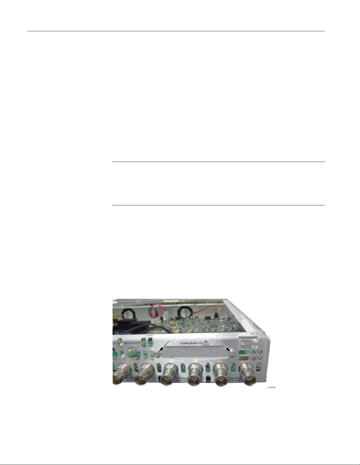
3. Remove the two screws that secure the blank cover from the Analog Audio
I/O hole.(See Figure 12.)
Figure 12: Remove blank cover for audio connector
30 WVR720UP, WVR820UP, and WVR830UP Upgrades

Upgrade installation
4. Replace three m
as illustrated. If an audio board was installed previously, you can leave the
three existing posts installed. (See Figure 13.)
ain board mounting screws with the three posts from this kit
Figure 13: Audio board post locations
5. Line up the BNC connectors to the holes in the rear panel and slide the audio
board into the mainframe until BNC connectors fully protrude through the
rear panel.
6. The audio board should sit firmly on all three posts.
WVR720UP, WVR820UP, and WVR830UP Upgrades 31

Upgrade installation
7. Secure the audi
from the kit. Tighten firmly, but not excessively. (See Figure 14.)
o board to the three mounting posts with the three T-15 screws
Figure 14: Audio board screws
8. Secure the eight BNC connectors using the eight lock washers and BNC nuts
from the kit.
9. Use a 3/16 in. nut driver to install the two retainer posts from this kit to secure
audio connector to the rear panel. (See Figure 15.)
Figure 15: Audio connector retainer posts
32 WVR720UP, WVR820UP, and WVR830UP Upgrades

Upgrade installation
10. Plug the audio c
Figure 16: Audio cable
11. Secure the cabinet top cover to its chassis with the 18 T-10 screws previously
removed.
12. Install the option software key. (See page 35, Install the option software key.)
able into connector J750. (See Figure 16.)
Audio board removal
NOTE. Use the supplied 62-pin DSUB connector to attach analog-audio signals
to the instrument. Solder wires to the connector as needed to accommodate the
desired audio inputs and outputs. Refer to the Safety and Installation Instructions
for the connector pin assignments.
Audio signals can be connected as either balanced or unbalanced. Be sure to use
a suitable cable when you are wiring balanced audio. An example of a suitable
cable is Belden 8451, which is a shielded twisted pair cable.
Alternatively, you can purchase an audio breakout cable (Tektronix part number
012-1688-00), which provides a two meter cable with XLR connectors for all
twelve inputs and eight outputs.
The optional audio circuit board installs above other optional hardware upgrade
circuit boards so you might need to temporarily remove it to install other upgrades.
You will reinstall the audio circuit board unless it is being replaced by Option DPE.
Perform these steps to remove the audio circuit board.
1. Remove the 5/16 inch nut and washers that secure the eight audio BNC
connectors (AES1-2 In through AES 7-8 In and AES 1-2 I/O through AES
7-8 I/O) to the rear panel.
2. Remove the two 3/16 inch retainer posts that secure audio connector to the
rear panel. (See Figure 17.)
WVR720UP, WVR820UP, and WVR830UP Upgrades 33

Upgrade installation
Figure 17: Audio connector
3. Unplug the audio cable from J750.
4. Remove the three T-15 screws securing the audio board. (See Figure 18.)
5. Lift the a
6. Return to your original installation procedure.
udio board out of the instrument and store it in a static safe location.
ure 18: Audio board installed
Fig
34 WVR720UP, WVR820UP, and WVR830UP Upgrades

Upgrade installation
Install the op
tion software key
Read the entire procedure before installing the software option key.
CAUTION. To prevent upgrade failure, your instrument must have the latest
version of s
installing the option key. (See page 14, Install software upgrade.)
1. Verify tha
2. Verify the IP address of the instrument:
a. Press the CONFIG button on the front panel.
b. Navigate to Utilities > Communications > Network Setup.
c. Note the IP address of the instrument.
d. If the instrument does not have an IP address set, ask your network
administrator for a valid IP address. Refer to the online help or the User
manual on how to set the instrument IP address.
3. Verify that you have a ccess to a PC with a Web browser application that is
connected to a network with access to the instrument.
oftware installed before installin g the hardware upgrade and before
t the instrument is powered on and connected to your local network.
4. Perform the following steps to enter the software option key:
a. On the PC, open your Web browser application.
b. In t
c. Click the Instrument Options linktoopentheActive WVR8200/8300
d. In the Key field, enter the 20-character option key string (with or without
e. Click the Submit button to enable the software option. The instrument
NOTE. If you purchased multiple options, the software option key supplied with
this kit activates all of the options you purchased.
he address bar of the Web browser, enter the IP address of
the instrument you are upgrading. This opens the Tektronix
WVR8200/WVR8300 Remote Interface screen.
Options screen.
dashes). The new option key is supplied in the Important Documents
envelope.
enables the option and adds the installed option to the list of currently
installed options shown at the top of the screen.
WVR720UP, WVR820UP, and WVR830UP Upgrades 35

Verify the upgrade
Verify the upg
Quick verification
rade
Perform the
installed and the instrument is functioning correctly:
1. Power on the
2. Verify the installed options by performing the following steps:
a. Press the CONFIG button on the front panel.
b. Navigate to Utilities > View Instrument Options to display the installed
c. Verify that the options installed prior to this upgrade are still enabled, and
NOTE. If the option(s) you just installed are not listed or if your previously
led options are not listed, contact Tektronix for assistance.
instal
3. Verify that the instrument passes the advanced diagnostic tests by performing
the f
following procedure to verify that the new option(s) have been
instrument.
options.
that the new option(s) you installed are enabled.
ollowing steps:
Detailed verification
a. In the Config menu, navigate to Utilities > Run Diagnostics.
b. Press the SEL button.
c. Press the right arrow key to highlight the box next to Run Advanced
Diagnostics. This box is located at the bottom of the display screen.
d. Verify that for each diagnostic test the result reads Pass.
e. When the test is complete, press the right arrow key to highlight the box
next to Exit to exit the diagnostics display.
f. If you want to view the diagnostics test results again, select View
Diagnostic Log from the Utilities menu.
NOTE. If a diagnostic test fails, contact Tektronix for assistance.
If you want to perform additional verification of the installed options, perform
the Incoming Inspection Tests found in the Specifications and Performance
Ver ification manual using the specified test equipment.
36 WVR720UP, WVR820UP, and WVR830UP Upgrades
 Loading...