

Page 1
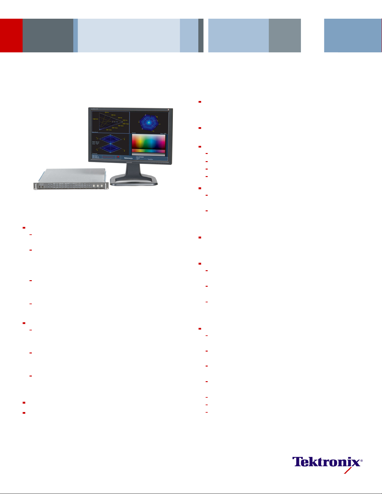
Advanced 3G/HD/SD-SDI Waveform Rasterizer
WVR8300 • WVR8200 Data Sheet
New Tektronix-patented Spearhead Display and Luma Qualified Vector
(LQV™) Display Facilitate Precise Color Adjustment for Post Production
Applications (Opt. PROD)
Tektro nix-paten ted Diamond and Arrowhead Displays for Gamut
Monitoring
Most Compre hensive Audio M onitoring (Opt. AD or Opt. DPE)
Multichannel Surround Sound*1display and flexible Lissajous display
ess mo nitoring to ITU-R BS. 1770-1 (Opt. AD or DPE)
5/B37/B39, TR-B22, and TR-B23 support
ality and Reliability Issues (Standard on WVR8300 and
Display Versatility
raticule on picture display enable easy identification of
d Usability
a, screenshots, and error log
ate centralized monitoring and control
Features & Benefits
Video/Audio/Data Monitor and Analyzer – All in One Platform
WVR8300 and WVR8 200 come standard with auto-detection of
HD/SD-SDI and multiple Dual Link video formats
Optional c
support (Opt. 3G), composite analog video support (Opt. CPS), as
well as analog and digital audio (Opt. AD) and Dolby E, Dolby Digital
Plus, and Dolby Digital audio (Opt. DPE) decoding and monitoring
WVR8300 also comes standard with Simultaneous Input Monitoring
capability, ANC Data Inspector, and numerical/graphical display of A/V
delay for
Multiple Input Mode allows monitoring of 2 to 4 SDI inputs
simultaneously (4-input mode requires Opt. 2SDI)
Superior
High-performance real-time eye pattern display, jitter measurements,
and patented cable length measurement (WVR8300 Opt. PHY or
WVR8200 Opt. EYE)
Most comprehensive eye pattern measurements including eye
amplitude, rise/fall time, and overshoot/undershoot measurements as
well as Te
Field-upgradeable HD/SD-SDI eye pattern input module to full
3G-SDI and HD/SD-SDI support with the purchase of an upgrade key
(WVR830UP Opt. 3G or WVR820UP Opt. 3G)
Black Picture and Tektronix-patented Frozen Picture Detection
Tektronix-patented Timing and Lightning Displays Facilitate Accurate
Adjustme
apabilities include 3G-SDI (Level A and Level B) formats
analog, digita l (with Opt. AD), and Dolby (Opt. DPE)
Physical L ayer Signal Integrity Analyzer
ktronix jitter waveform display (WVR8300 Opt. PHY only)
nt of Critical Plant Timing
Audio Loudn
Comprehensive Dolby metadata decode and display (Opt. DPE)
Dolby E Guard Band meter with user-defined limits (Opt. DPE)
Most Comprehensive ANC Data Monitoring
Simultaneous CEA708/608 Closed Caption monitoring; Teletext and
OP47 subtitle monitoring
Detect and decode ANC data including AFD, WSS, Video Index,
TSID, V-Chip, Broadcast Flag/CGMS-A, VITC, LTC, and ANC TC
ARIB STD-B3
Most In-depth Digital Data Analysis Helps Quickly Resolve Difficult
Content Qu
available as Option DAT on WVR8200)
Unmatched
FlexVu™, the most flexible four-tile display, tailors to various
application needs to increase productivity
Standard and user-definable Safe Area Graticules facilitate editing
and fo rmat conversions tasks, reducing the need for reworks
Active Format Description (AFD) detect, decode, and automatically
adjusted g
aspect-ratio related issues
Unmatche
CaptureVu®advanced video frame data capture simplifies
troubleshooting and equipment setup
32 instrument presets for quick recall of commonly used
configurations tailored to engineers or operators
Front-panel USB port enables easy transfer of presets, captured video
frame dat
Front-panel headphone port enables quick verification of selected
audio pair
Intuitive menu structure and context-sensitive help
Extensive alarms, status reporting, and error logging
SNMP and Ethernet remote interface capabilities and GPI control
facilit
Page 2
Data Sheet
Analysis (including ANC Data Ins pector), A/V Delay Measurement, and
in-depth Simultaneous Input Monitoring which makes Tektronix the brand
of choice for ap
unquestionable accuracy.
The WVR8300 features the complete range of options of the product family
and comes standard with HD/SD-SDI and Dual Link video formats support.
It provides high-performance monitoring and measurement for applications
for a wide range of formats from Composite Analog to SD-SDI, HD-SDI,
Dual Link video formats, and 3G-SDI video signals. The WVR8300 offers
support for a variety of audio formats for analog, digital AES/EBU, digital
embedded, Dolby Digital, Dolby Digital Plus, and Dolby E.
Video Monitoring Standards and Formats
3G-SDI (Level A and Level B) – Option 3G
High Definition SDI – Standard
Standard Definition SDI – Standard
Dual Link (4:2:2, 4:4:4, alpha chan nel, 10 bit, 12 bit) – Standard
Composite Analog Video – Option CPS
Multiple Input Mode 2 SDI Inputs – Standard
Multiple Input Mode 4 SDI Inputs – Option 2SDI
plications that require deep signal and content analysis with
Multiformat support grows with your needs.
Applications
ing and Compliance Checking in Content Distribu tion and
Monitor
Broadcast
Quality C on trol in Content Production and Post Production
Equipment/System Qualification and Troubleshooting for Installation and
Maintenance of Content Creation and Distribution Facilities
Research and Development of Professional Video Equipment
*1Audio Surround Sound Display licensed fromRadio Technische WerksüttenGmbH and Co. KG (RTW).
WVR8300
The mea
precision capabilities such as Physical Layer Measurements, Digital Data
surement and monitoring capabilities of the WVR8300 provide
Color Gamut Monitoring
Arrowhead Display – Standard
Diamond and Split Diamond Displays – Standard
Spearhead Display – Option PROD
Luma Qualified Vector (LQV™) – Op tion PROD
Audio Monitoring Standards and F ormats
Analog, Digital AES/EBU, Digital Embedded – Option AD
Analog and Digital including Dolby Digital, Dolby Digital Plus, and
Dolby E – Option DPE
Measurement and Analysis
Automated Eye Pattern and Jitter Measurements – Option PHY
Color B ar and Pathological Signal Generation – Option PHY
Digital Data Analysis – Standard
ANC Data Inspector – Standard
Simultaneous Input Monitoring – Standard
3D Video Monitoring – S tandard
Audio/Video Delay Measurement – Standard
2 www.tektronix.com
Page 3
Advanced 3G/HD/SD-SDI Waveform Rasterizer — WVR8300 • WVR8200
Both WVR8300 and WVR8200 support flexible combinations of options and
field upgrades, providing an excellent solution for multiformat environments
while protecti
feature availability by model please refer to the section of this document on
ordering information.
ng your investment. For comp lete details regarding option and
WVR8RFP
3G-SDI mon
itoring, jitter measurement, and test generator.
WVR8200
The WVR8200 provides an ideal solution for advanced monitoring of
analog, digital, high frame-rate digita l video, and multiple audio formats.
This flexible solution comes standard with HD/SD-SDI and Dual Link video
monitoring and can be equipped with options and upgrades to monitor
3G-SDI and/or composite analog video. The WVR8200 is an intelligent
choice th
needs. Available audio options include support for analog, digital AES/EBU,
digital embedded, Dolby Digital, Dolby Digital Plus, and Dolby E formats.
at prepares you for format transitions and growing monitoring
Video Monitoring Standards and Formats
3G-SDI (L
High Definition SDI – Standard
Standard Definition SDI – Standard
Dual Lin
Composite Analog Video – Option CPS
Multiple Input Mode 2 SDI Inputs – Standard
Multip
Color G
Arrowhead Display – Standard
Diamond and Split Diamond Displays – Standard
Spearh
Luma Qualified Vector (LQV™) – Option PROD
Audio Monitoring Standards and Formats
Analog, D igital AES/EBU, Digital Embedded – Option AD
Analo
DolbyE–OptionDPE
Measurement and Analysis
Eye Pattern Display and Jitter Readouts – Option EYE
Digi
ANC Data Inspector – Option DAT
Simultaneous Input Monitoring – Option 3D
3D Vi
evel A and Level B) – Option 3G
k (4:2:2, 4:4:4, alpha channel, 10 bit, 12 bit) – Standard
le Input Mode 4 SDI Inputs – Option 2SDI
amut Monitoring
ead Display – Option PROD
g and Digital including Dolby Digital, Dolby Digital Plus, and
tal Data Analysis – Option DAT
deo Monitoring – Option 3D
The WVR8300
remote front panel (WVR8RF P) which has the same control button
and knob configuration as the front panel on the instrument. The new
WVR8RFP allows operators to access and control the WVR8300 or the
WVR8200 from a distance of up to 1000 ft. with power supplied from the
base instrument through the cable. Users can also choose to connect the
WVR8RFP wit
distance of the cable r un to 4000 ft.
and the WVR8200 can be controlled by the newly designed
h an external 12 V DC power source which can extend the
From Composite Analog to 3G-SDI Advanced
Digital Video – All in One Platform
Ideal for multiformat enviro nment s, the WVR8300 and WVR8200 advanced
m rasterizers provide flexible options and field-installable upgrade
wavefor
kits to monitor diverse video types including 3G-SDI, Dual Link, HD/SD-SDI,
and composite analog video.
Both WVR8300 and WVR8200 come standard with Dual Link SMPTE
372M compliant monitoring, SMPTE 352M automatic format detection, and
able display of Alpha Channel as well as 2K Dual Link monitoring
select
with XYZ Color Space.
These instruments allow for monitoring of Link A, Link B, or the combined
Dual Link input with a comprehensive set of displays and status reporting
tools. The Tektronix-patented Timing display, which measures timing
en Link A and Link B of the Dual Link signal, proves a valuable ally to
betwe
maintain correct timing between the two links.
To support the latest production trends for high-definition 1080p 50/59.94/60
content, the W VR8300 and WVR8200 provide optional capabilities to
monitor the 3G-SDI format. Option 3G for the WVR8300 and WVR8200
les m onitoring of SMPT E 425M Leve l A (directly mapped) and Level B
enab
(mapped from Dual Link) signals. Level B support for 2×HD (1920×1080 or
1280×720) is ideally suited for 3D distribution of Left and Right Eye signals
within a 3G-SDI multiplex.
Monitoring display modes such as Waveform , Vector, Gamut, Timing,
tus, Picture, and Audio, as well as automated physical-layer
Sta
measurements and in-depth data analysis are available for 3G-SDI and
other input formats.
Both WVR8300 and WVR8200 support any combination of video and audio
format options, so these instruments excel in multiformat environments and
olve with your needs to protect your investment.
ev
www.tektronix.com 3
Page 4
Data Sheet
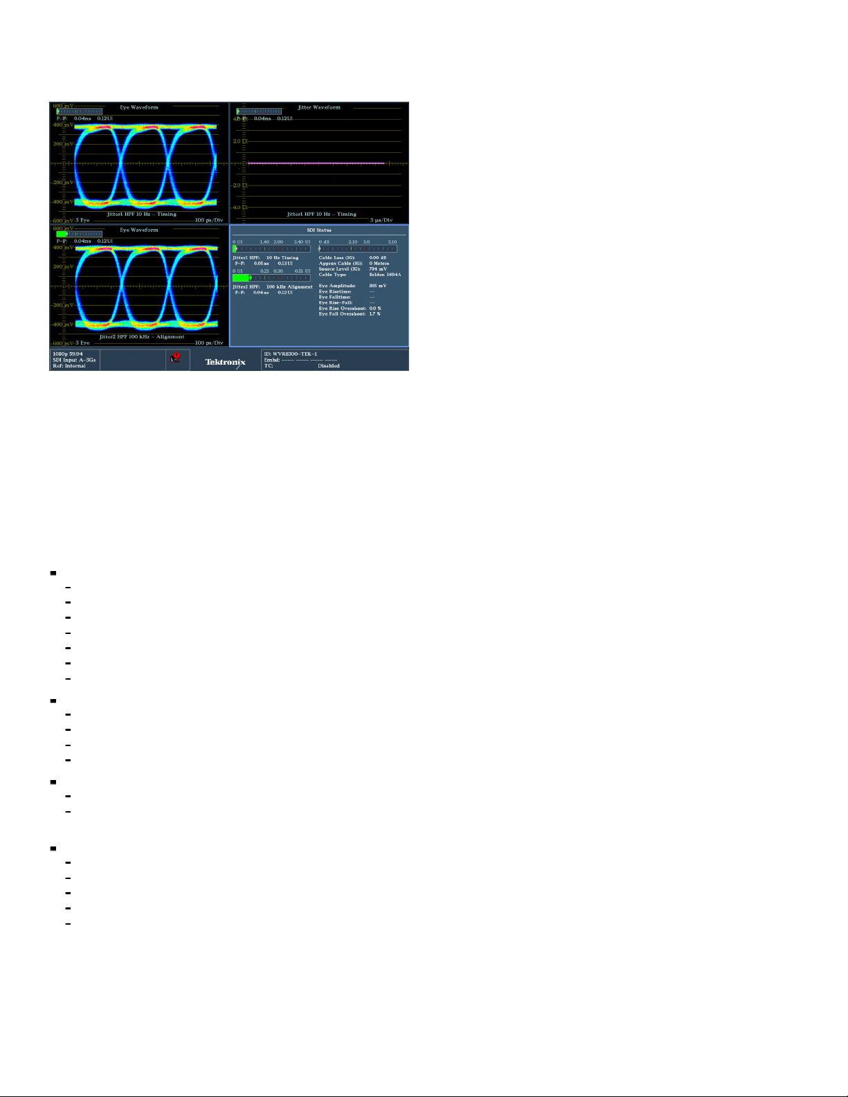
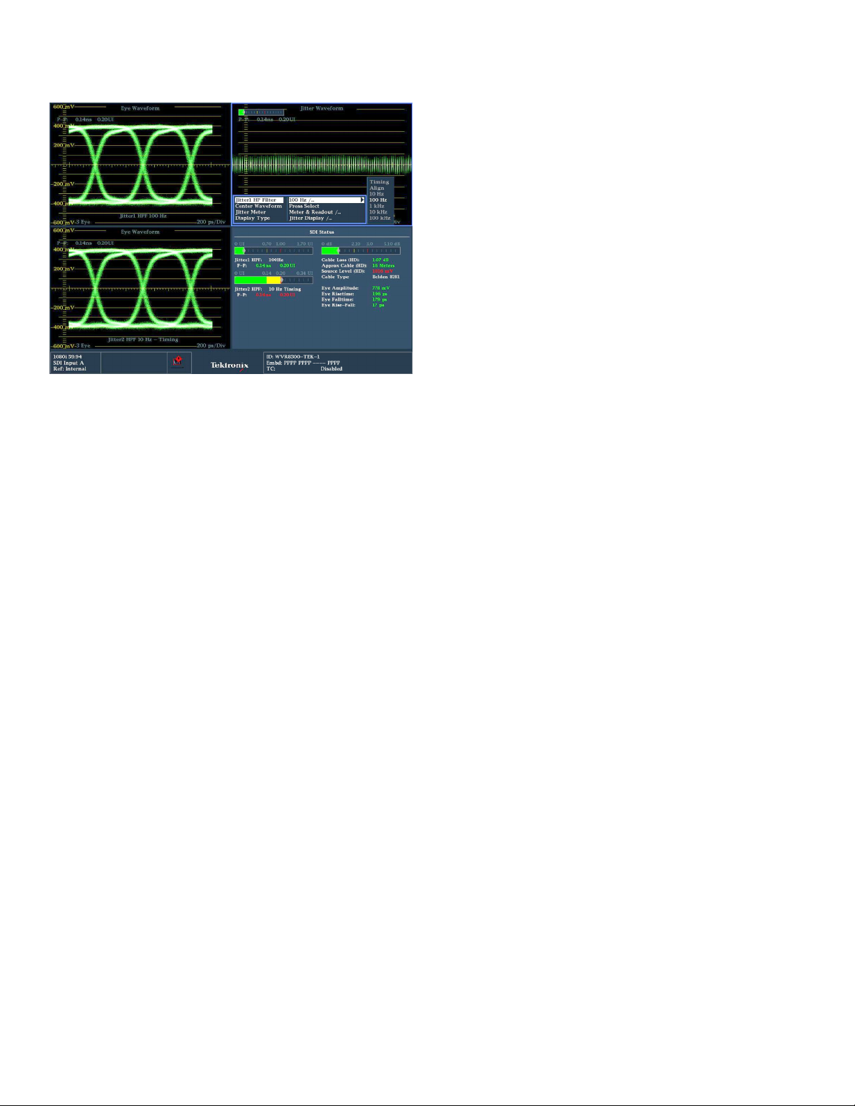
Physical-layer options provide precise measurements for video signals.
Unmatched
Performan
Content Di
Most Adva
The WVR8300 and WVR8 200 high-performance waveform rasterizers offer
the most c
When equipped with Option 3G and relevant physical-layer options for
omprehensive physical-layer signal measurements for engineers.
Measurement and Monitoring
ce for Content Creation and
stribution
nced Physical Layer Measurement Solutions
each model, the WVR8300 and WVR8200 can perform 3G-SDI eye pattern
display, jitter measurements, and cable length measurements (Option PHY
for WVR8300 or O
unique capabilities such as reporting jitter levels above 1 UI and providing
various jitter filters from 10 Hz to 100 kHz for SD/HD/3G-SDI signals. An
easy-to-interpret gauge provides direct readout for jitter measurements.
Users can configure timing jitter and alignment jitter readouts to be
displayed simultaneously to effectively isolate the sources of jitter. The SDI
Status displa
cable loss, and estimated cable length measurements.
With FlexVu™, users can simultaneously display timing jitter and alignment
jitter values, cable parameter measurements, and display different eye
patterns to help quickly diagnose and resolve problems related to SDI timing
jitter or cable attenuation. The infinite persistence mode of the waveform
rasterizer can also be used to more easily view the eye opening of the
physical-layer signal.
In addition, the WVR8300 (with Option PHY) can also perform automated
eye amplit
measurements, and provide jitter waveform display to view jitter related
to line and field rates. All these capabilities help broadcasters and
network operators detect and diagnose signal quality problems quickly and
efficiently. WVR8300 with Option PHY also include s multirate HD/SD-SDI
and 3G-SDI (with Option 3G) color bar and pathological signal generation
ties to provide engineers with a simple signal source for quick signal
capabili
path verification during system and/or equipment setup and troubleshooting.
ption EYE for WVR8200). Options PHY and EYE provide
y s ummarizes key signal parameters such as signal strength,
ude, automated rise/fall time, automated overshoot/undershoot
4 www.tektronix.com
Page 5
Advanced 3G/HD/SD-SDI Waveform Rasterizer — WVR8300 • WVR8200
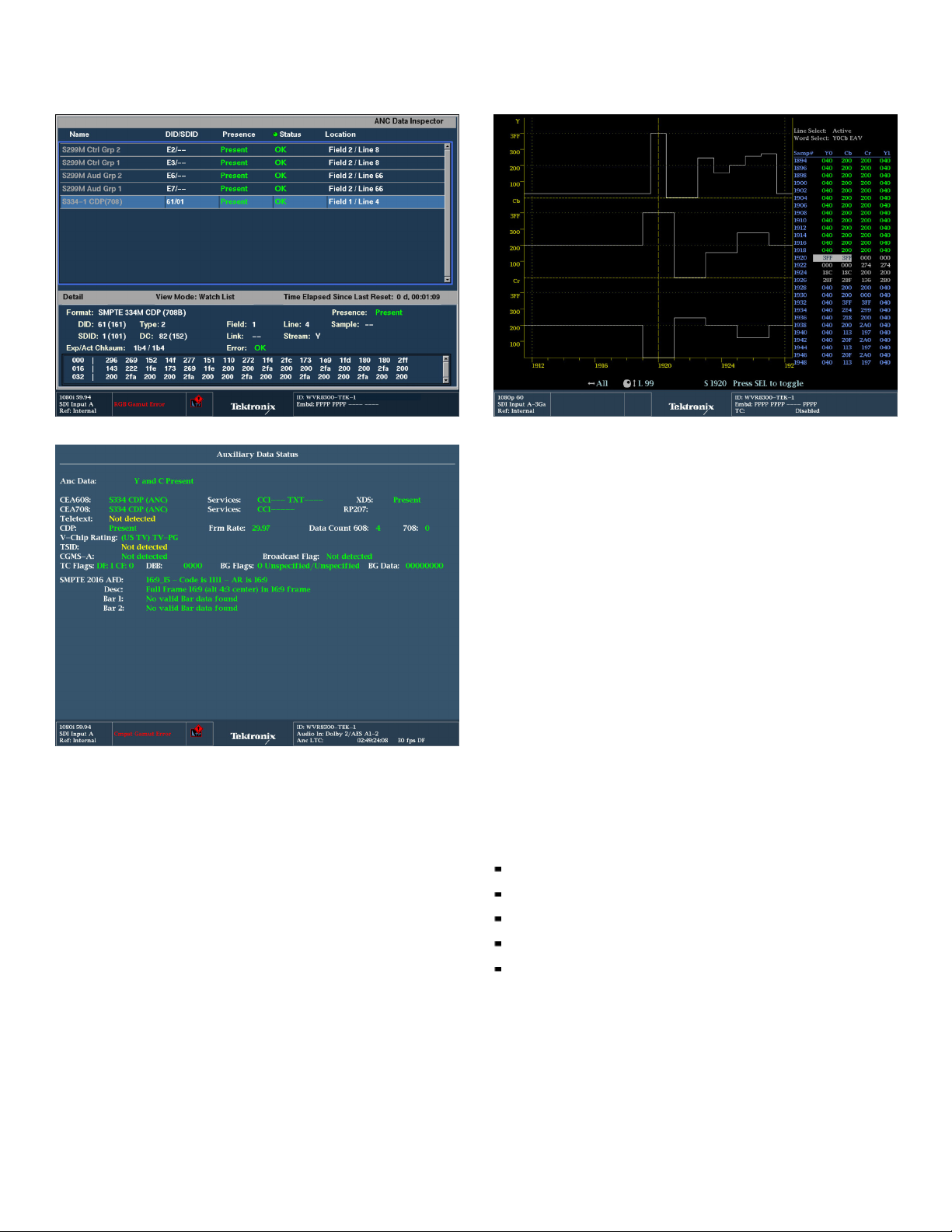
ANC Data Inspector and CaptureVu provide detailed content analysis.
Monitoring of Ancillary data (Closed Caption, Time Code, and AFD) using Aux Data
Status.
Superi
or Data Analysis Capabilities for Engineers and
Operators
The new ANC Data Inspector (standard on WVR8300 and available on
WVR8200 with Option DAT) provides an industry-leading solution to help
broadcasters easily and accurately ensure that all required VANC data is
present and correctly con figured through an intuitive ANC data display.
In contrast to other solutions, the ANC Data Inspector enables operators to
easily and quickly ensure that the VANC data is present and free of errors.
When errors are detected, engineers are quickly guided to a more detailed
f the data packet content for further analysis.
view o
With FlexVu™, each picture display tile can display different CEA708/608
d Caption and individual Teletext subtitles. Teletext subtitle pages can
Close
be decoded in either WST or OP47 format.
xiliary Data Status display (standard on both the WVR8300 and
The Au
WVR8200) provides summary information on Active Format Description
isplay provides detailed pixel-by-pixel information.
Datalist d
(AFD) per SMPTE 2016, Video Index Aspect Ratio, Wide Screen Signaling
(WSS), V-Chip, TSID, CGMS-A, Broadcast Flag, CEA708/608 Closed
Caption, Teletext, and Time Code information.
Tod ay there is a wide array of metadata that provides information to a
variety of equipment through the processing chain. Monitoring of this
metadata is critical to ensure that the processing equipment correctly
the signal. For instance, correct format of the AFD ensures that the
handles
aspect ratio on the display is correctly formatted and the automated AFD
graticule is available for the picture display of the WVR8300 and WVR8200
along w ith the binary data an d text description for easy monitoring.
The WVR8300 and WVR8200 can also monitor Dolby metadata embedded
in the Vertical Ancillary (VANC) data space per SMPTE 2020.
The Datalist display, available as standard on the WVR8300 and available
as part of option DAT on the WVR8200, provides detailed information on
the actual data values in HD/SD-SDI and 3G-SDI (with Option 3G) input
signals. Users can easily use this display to locate protocol errors in the
ignals.
input s
The right side of the display shows the data values in hexadecimal, decimal,
ry format and uses the following color coding for easy identification of
or bina
data types and errors:
Green – Active video data
Blue – Data in horizontal or vertical blanking intervals
White – EAV, SAV, and other reserved words
Yellow – Data outside nominally allowed values
Red – Data with illegal values
The left side of display shows un-interpolated digital values plotted against
sample numbers as a digital waveform. You can configure this unique
ay in either Video mode or Data mode.
displ
In Video mode, the display shows the Y, Cb, Cr values aligned temporally,
ffset vertically. Like the waveform display, you can configure the
but o
display to show 1, 2, or all 3 components.
www.tektronix.com 5
Page 6
Data Sheet
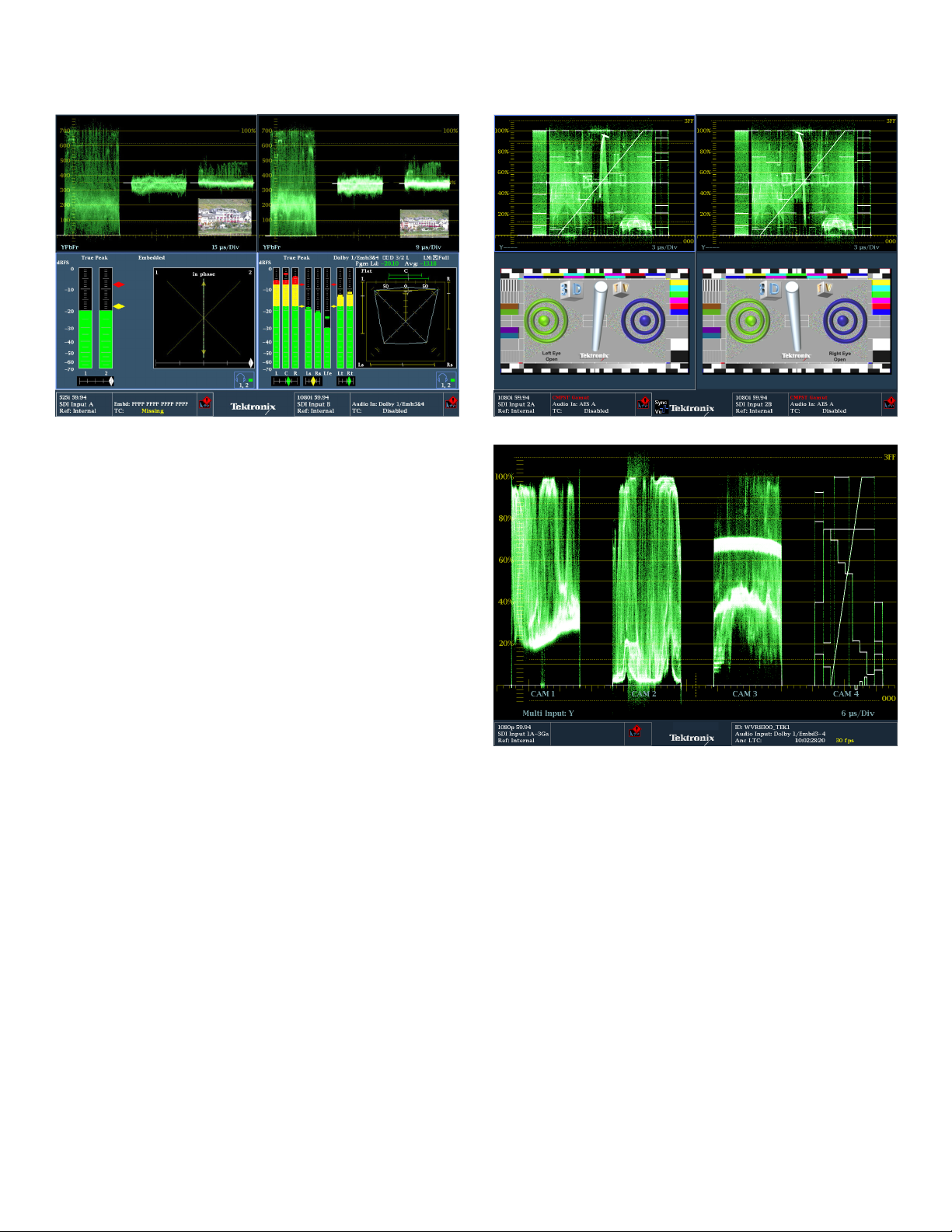
Simultaneous display, virtually two instruments in one.
Full-featured Simultaneous Input Monitoring Boost
Versatility
The Simultaneous Input Monitoring (SIM) capability of the WVR8300 takes
multiformat monitoring to a new level. This capability helps operatio
quickly determine if a video quality problem existed in the input signal or
arose in their facility. It enables engineering staff to quickly detect, diagnose,
and resolve technical problems introduced in a piece of video equipment
by comparing the input and output signals at each point in the chain. This
feature is also especially helpful when checking for transparency during
format conversion.
FlexVu™ enables flexible and intuitive configuration of displays from two
monitored inputs. User can display simultaneous fault detection, status
reporting, alarm generation, and error log ging. SIM is ideal for transmission
monitoring of simultaneous HD and SD programs. It is also ideal for
monitoring stereoscopic 3D content in production and post production
applications by simultaneously monitoring the L eft Eye signal and the Right
Eye signal.
SyncVu™ is used in conjunction with SIM mode for 3D applications when
input A is used for the Left Eye and input B is used for the Right Eye. When
SyncVu is enabled the Left and Right tile displays are synchronized so that if
a Picture Tile is selected for Tile 1, automatically Tile 2 displays a Picture
Tile in exactly the same mode as Tile 1. This enables the user to quickly
ure the instrument identically for Left and Right Eye 3D monitoring.
config
nal staff
ous 3D display of Left Eye and Right Eye signals.
Simultane
Multiple Input mode display of 4 SDI inputs with input labels for each signal.
ple Input mode can be used to monitor up to 4 SDI inputs
Multi
simultaneously when in Full Screen mode (4-input mode requires Opt.
2SDI). This type of display is ideal for camera balance applications to check
the video level a cross multiple inputs. This Multiple Input mode is available
within Waveform, Vector, Lightning, Diamond, Arrowhead, and Spearhead
(with Option PROD) allowing for the comparison of video inputs across a
ariety of these displays.
wide v
6 www.tektronix.com
Page 7

Advanced 3G/HD/SD-SDI Waveform Rasterizer — WVR8300 • WVR8200
3D Left and
SIM mode.
Right Eye images showing a Difference Map and Red/Cyan Anaglyph using
3D Measurement and Monitoring
The 3D measurements and displays are standard on the WVR8300 and
available as Option 3D on the WVR8200. A 3D image is comprised of a Left
Eye a nd Right Eye view feed as two separate HD-SDI signals or combined
within a 3G Level B format. Within the instrument a variety of different
3D monitoring modes are available to assist the user in determining the
ce between the Left Eye and Right Eye views. From this disparity
differen
difference between the two left and right images the depth of an object
within the image can be determined.
For monitoring purposes a variety of displays can be set up within the
Picture mode:
Difference Map Display – A subtraction of the two luma video signals L-R
or R-L to
produce a grayscale difference map image to see the difference
between left and right images.
Red/Cyan Anaglyph Display – T he left image is shown in red and the
right image is shown in cyan, with identical left and right objects shown in
rome. This allows the user to isolate differences between objects
monoch
and gauge the depth of the object within the image.
Green/Magenta Anaglyph Display – The left image is shown in green
and the right image is shown in magenta, with identical left and right
s shown in monochrome. If an object appears in magenta and then
object
green this indicates that the object is coming out from the screen plane.
Similarly if the object appears in green and then magenta the object is
d the screen plane.
behin
erboard Display – This picture display shows a block of the image
Check
from the left eye and then the next block shows the image from the right
eye in a 16×9 checkerboard pattern. This helps the user compare the
ls and color of the signal between the left and right images.
leve
These modes help the user compare the disparity between the left and right
es and can assist in interpreting the depth of the objects within the
imag
image.
3D Left and R
display usi
3D Left and Right Eye images showing Disparity Grid and Disparity Cursor measurement
using SIM mode.
For m
ight Eye images showing Green/Magenta Anaglyph and Checkerboard
ng SIM mode.
easurement of the depth of an object within the image a Disparity Grid
can be overlaid over the picture with a horizontal disparity between 1 to 15%
of screen width and a vertical disparity of 50%, 25%, or 10% that can be
selected by the user. The horizontal and vertical position controls allow the
Disparity Grid to be moved around within the picture display to gauge the
depth of objects within the image.
A set of Disparity Cursors are also available for precise measurement of
horizontal disparity of an object between the Left and Right Eye images.
out is given of the pixel difference between the cursors and the
Read
percentage of disparity of an object.
www.tektronix.com 7
Page 8

Data Sheet
See and Sol
ve™ displays detect and address problems quickly and efficiently.
See and Solve™ with Tektronix Displays
Tektronix See and Solve™ d isplays simplify video monitoring tasks such as
calibration, error detection, and content correction allowing users to detect
errors at a glance and troubleshoot them efficiently.
Specialized Session and Status displays provide summarized yet
comprehensive reports of conditions and measurements of content
parameters.
The Black and Frozen frame detection can be used to alert the operator to a
problem in the transmission chain. These and other errors can automatically
be logged in the Error Log and provided as a report.
The powerful Error Log is configurable and provides detailed reports for up
to 10,000 events that can be downloaded using a web browser or saved
through a
front panel connection to a USB flash drive. Alarms can also
activate ground closures and SNMP traps simplifying centralized monitoring
of multiple programs.
The FlexVu™ four-tile display provides maximum flexibility to increase your
productivity. Unlike instruments with predetermined view combinations or
limited choices, FlexVu™ lets you create a multiview display tailored to your
specific needs and work practices. Each tile can be configured to enable
easy signal analysis such as multiple alarm and status screens, different
a Graticules and cursors on each tile, and more.
Safe Are
Tektron ix displays offer the sharpest CRT-like trace quality for clear
m and vector monitoring without pixelation distortions. The familiar
wavefor
video waveform display can show SD/HD/3G-SDI signals in RGB, YPbPr,
YRGB, or composite formats. Signal components can be displayed in either
Parade or Overlay mode. For composite analog video, NTSC and PAL
signals can be displayed with luma, chroma, and luma+chroma filtering.
The vector display offers user-selectable graticules, color targets (75% or
and color axis.
100%),
FlexVu – The display that adapts to your work practices.
The Tektr
onix-patented Diamond, Split Diamond, and Arrowhead gamut
displays simplify the process of verifying gamut compliance.
The Diamo
nd and Split Diamond displays help easily identify and correct
RGB gamut errors in digital video signals. The Arrowhead display saves
time in verifying composite gamut compliance for digital video signals.
User-selectable gamut thresholds let you tailor these displays and the
associated gamut alarms to your particular compliance standards.
You can also select bright-up conditions to see the location of gamut errors
on the picture display.
The WVR8300 and WVR8200 also feature new optional advanced color
gamut monitoring capabilities including the Tektronix-patented Luma
Qualified Vector (LQV™) display and Spearhead display which, when used
in conjunction with Tektronix proprietary Diamond and Split Diamond gamut
displays, provide the most comprehensive color gamut monitoring tools
le for precise color gamut adjustment s (Option PROD).
availab
The picture display can simultaneously detect and decode CEA708/608
Caption. Teletext subtitle pages can also be decoded in either 625
Closed
formats or using OP47 Ancillary data. Flexible Safe Area Graticules allow
for quick placement of graphics, titles, or logos. Using FlexVu™, users can
see two or more pictures with different graticules.
The CaptureVu
®
feature on the WVR8300 and WVR8200 allows users to
capture, store, and download the data of a video frame to recreate displays
and compare the live signal to captured data for easy troubleshooting of
intermittent errors or for analyzing fault conditions at remote sites.
8 www.tektronix.com
Page 9

Advanced 3G/HD/SD-SDI Waveform Rasterizer — WVR8300 • WVR8200
Surround S
ound, Dolby Metadata, Audio Session, and Loudness Session.
Complete Monitoring Tool Set for Optimum Sound
Quality
The WVR8300 and WVR8200 provide high-quality digital filtering
and oversampling to insure precise, reliable, and repeatable audio
measurements. For easy monitoring, the WVR audio options provide format
ection and flexible mapping of audio inputs to analog or digital audio
auto-det
outputs for connection to external devices.
The Surro
und Sound*
1
display provides intuitive graphical representation
of channel interaction in a system. The Bars display provides indicators for
faults, audio levels, and Dolby format information. The flexible Lissajous
display allows the selection of any two audio channels.
Loudness measurements are made to ITU-R BS.1770-1. A Loudness
meter is available within the Audio display that provides Short and Infinite
Loudness measurements. The Loudness session display graphically p lots
Loudness measurement over time from 90 seconds to 30 hours. The
s measu rement s can be downloaded through the network or saved
Loudnes
to USB for further analysis.
ized audio displays provide deeper inspection of the signal
Special
and make the WVR8000 Series instruments the most comprehensive
waveform and audio rasterizers available. The audio session displays
summarize levels, faults, and number of active bits for each channel. These
instruments also feature Audio Control Packet Data and Channel Status
displays.
The Dolby Status display (in Option DPE) gives an in-depth view of
integrated or VANC metadata and Dolby E Guard Band timing and
onization.
synchr
User-configurable thresholds for the Dolby E Guard Band timing
ement (in Option DPE) are available as well as Dolby E Guard Band
measur
timing and trigger alarms based on their specific guard band parameters.
*1Audio Surround Sound Display licensed from Radio Technische Werksütten GmbH and Co. KG (RTW).
Timing and
Lightning displays simplify timing tasks.
Facility Timing Made Easy
Audio/Video synchronization is an important challenge in the processing of
video materials. The WVR8300 displays the A/V delay on a graphical bar
indicator. The measurement readout gives facility engineers the necessary
tools to ensure system integrity and facilitate A/V delay compliance. This
feature provides out-of-service measurement of A/V delay for analog or
audio and video formats. A TG700 is required to generate the SDI
digital
signal which contains the audio and video sequ ence that can be distributed
through the system and measured by the WVR8300.
The Tektronix-patented Timing display makes facility timing easy through
a simple graphical representation which shows the relative timing of the
input signal and the reference signal (or a saved offset reference) on an X-Y
axis. When in SIM mode the Timing display can be used to time each input
relative to the reference or measure the timing between each input.
The Lightning display shows luma and chroma amplitudes and helps users
verify component timing using a color bar signal. The Tektronix-patented
display (standard on both the WVR83 00 and WVR8200)
Bowtie
complements the timing measurement capability of the Lightning display.
Using a special Bowtie test signal in component format, this display helps
make precise and accurate measurements of interchannel amplitude and
timing. The SCH Phase display helps quickly verify this critical timing
parameter of composite analog video signals.
www.tektronix.com 9
Page 10

Data Sheet
Video Input and External Reference Formats S upported
Automatic Detection of a Wide Range of Signal Formats
The WVR8300 and WVR8200 waveform rasterizers accept a wide variety of input signal formats and external references. The rasterizer will automatically detect the signal
format and establish the appropriate settings for the various displays.
External Reference Inputs
Setting
NTSC
59.94 Hz
PAL
50 Hz
BT601
483i,
59.94 Hz
(525)
BT601
576i,
50 Hz
(625)
296M
720p,
23.98 Hz
296M
720p,
24 Hz
296M
720p,
25 Hz
296M
720p,
29.97 Hz
296M
720p,
30 Hz
296M
720p,
50.00 Hz
296M
720p,
59.94 Hz
296M
720p,
60.00 Hz
240M
1035i,
59.94 Hz
240M
1035i,
60 Hz
274M
1080i,
50 Hz
274M
1080i,
59.94 Hz
274M
1080i,
60 Hz
274M
1080p,
23.98 Hz
274M
1080p,
24 Hz
274M
1080p,
25 Hz
Opt.
CPS
STDSDSTD
HD NTSC PAL 50 Hz 59.94 Hz 60 Hz 23.98 Hz 24 Hz 50 Hz 59.94 Hz 60 Hz 23.98 Hz 24 Hz
XX
XX
XX X X
XXX X
Bi-level Sync
XX X X X X
XXXXX
XXX X
XX X X
XXX
XXX X
XX X X X
XXXXX
XX X X
XXXXX
XXX X
XX X X
XXXXX
XX X X X X
XXXXX
XXX X
Tri-level 720p Tri-level 1080p
Tri-level 1080i 1080 SF
10 www.tektronix.com
Page 11

Setting
274M
1080p,
29.9 Hz
274M
1080p,
30 Hz
274M
1080sf,
23.9 Hz
274M
1080sf,
24 Hz
274M
1080sf,
25 Hz
274M
1080sf,
29.9 Hz
274M
1080sf,
30 Hz
Opt.
CPS
STDSDSTD
HD NTSC PAL 50 Hz 59.94 Hz 60 Hz 23.98 Hz 24 Hz 50 Hz 59.94 Hz 60 Hz 23.98 Hz 24 Hz
XX X X
XXX
XX X X X X
XXXXX
XXX X
XX X X
XXX
Bi-level Sync
Advanced 3G/HD/SD-SDI Waveform Rasterizer — WVR8300 • WVR8200
External Reference Inputs
Tri-level 720p Tri-level 1080p
Tri-level 1080i 1080 SF
Supported Dual Link Formats
Format
Dual Lin k
1920 × 1080
Sample Structure Frame/Field Rates
4:2:2 YCbCr 10 bit 60, 60/1.001, and 50
4:4:4 RGB
4:4:4:4 RGB +A 10 bit
4:4:4 RGB 12 bit
4:4:4 YCbCr 10 bit
4:4:4:4 YCbCr +A 10 bit
4:4:4 YCbCr 12 bit
4:2:2 YCbCr 12 bit
4:2:2:4 YCbCr +A 12 bit
2048 × 1080
4:4:4 RGB
4:4:4:4 RGB +A 10 bit
4:4:4 RGB 12 bit
4:4:4 YCbCr 10 bit
4:4:4:4 YCbCr +A 10 bit
4:4:4 YCbCr 12 bit
4:2:2 YCbCr 12 bit
4:2:2:4 YCbCr +A 12 bit
4:4:4 XYZ 12 bit
progressive
30, 30/1.001, 25, 24 and
24/1.001 progressive, PsF
60, 60/1.001, and 50
fields interlaced
30, 30/1.001, 25, 24, and
24/1.001 progressive, PsF
Supported 3G Single Link Formats
Format
3G-SDI Form ats
Single Link
×1080
1920
Sample Structure
4:2:2 YCbCr 10 bit
Level A and Level B
4:2:2 YCbCr 10 bit
4:4:4 YCbCr 10 bit
4:4:4:4 YCbCrA 10 bit
Level B
4:4:4 RGB 10 bit
4:4:4:4 RGB +A 10 bit
Level B
4:4:4 RGB 12 bit
Level B
4:2:2 YCbCr 12 bit
4:2:2:4 YCbCrA 12 bit
Level B
4:4:4 YCbCr 12 bit
Level B
2048 × 1080
4:4:4 RGB 12 bit
Level B
4:4:4 XYZ 12 bit
Level B
2×HD
1920 × 1080
2×HD
1280 × 720
4:2:2 YCbCr 10 bit
Level B
4:2:2 YCbCr 10 bit
Level B
Frame/Field Rates
9.94, 60 progressive
50, 5
23.98, 23.98sF, 24, 24sF,
25, 25sF 29.97, 29.97sF,
30, 30sF progressive
50, 59.94, 60 interlaced
23.98, 23.98sF, 24, 24sF,
25, 25sF, 29.97, 29.97sF,
30, 30sF progressive
23.98, 23.98sF, 24, 24sF,
25, 25sF, 29.97, 29.97sF,
30, 30sF progressive
50, 59.94, 60 interlaced
23.98, 24, 25, 29.97, 30,
50, 59.94, 60 progressive
www.tektronix.com 11
Page 12

Data Sheet
Characteristics
Composite Vid
Characteristic
Formats Supported NTSC, NTSC no setup, PAL
Inputs Two, only one active at a time
Input Type
Input Dynamic Range
Maximum Operating
Amplitude
Absolute Maximum Input
Voltage
DC Input Impedance 20 kΩ, nominal
Return Los
Crosstalk between
Channels
Loopthrough Isolation
DC Offset with Restore
Off
DC Restore
uation
Atten
Slow Mode Typical peaking 8% at 50 Hz and 60 Hz
Lock Range ±50 ppm remains locked
rnal Reference
Exte
Characteristic
Input Type
DC Input Impedance 15 kΩ,typical
Return Loss
Serial Digita l Waveform Vertical Cha racteristics
Characteristic
Vertical Measurement
Accuracy
Gain
Frequency Response
Characteristic
HD
uminance Channel
L
Y)
(
Chrominance
Channels (Pb, Pr)
SD
Luminance Channel
(Y)
Chrominance
Channels
eo Interface (Option CPS)
Description
Passive loopthrough BNC, 75 Ω compensated
±6 dB (typical)
–1.8 V to +2.2 V, DC + peak AC (typical)
–6.0 V to +6.0 V, DC + peak AC
s
>40dBto6MHz,poweron(typical)
>40dBto10MHz(typical)
>46dBto6MHz(typical)
35 dB, power off (standard amplitude video)
>60dBto6MHz(typical)
>70dBto6MHz(typical)
<20 mV (typical)
nd 60 Hz
50 Hz a
Fast mode >95% attenuation, Slow mode <10%
attenuation, <10% peaking
Description
Passive loopthrough BNC, 75 Ω compensated
>40dBto6MHz,>35dBto30MHz(typical)
Description
At1X,±0.5%;at5X,±0.2%of700mVfull-scalemode
X1, X2, X5, and X10
Description
0 kHz to 30 MHz ±0.5%
5
50kHzto15MHz±0.5%
50kHzto5.75MHz±0.5%
50kHzto2.75MHz±0.5%
Analog Comp o site Waveform Vertical Characteristics (Option
CPS)
Characteristic
Vertical Measurement
Description
±1% all gain settings
Accuracy
Gain
Frequency Response
X1, X2, X5, and X10
Flat to 5.75 MHz, ±1%
Waveform Horizontal Sweep Characteristics
Characteristic
Description
Sweep Timing Accuracy ±0.5%, all rates, fully digital system
Sweep Linearity 0.2% of time displayed on screen, fully digital system
Vector Characteristics
Characteristic
Vector Amplitude
Description
±2%
Accuracy
Vector Phase Accuracy
±2°
Audio Characteristics (Optional Capability)
Characteristic
Level Meter Resolution
Description
0.056 dB steps at 30 dB scale, from full scale to
–20 dBFS
User-selectable Scales
Analog
dBu, Din, Nordic, VU, IEEE PPM, BBC Scale, and user
definable
Digital
dBFS, Din, Nordic, VU, IEEE PPM, BBC Scale, and user
definable
Meter Ballistics
Defined/Programmable
table from true peak, PPM type 1, PPM Type 2, and
Selec
nded VU
Exte
Mute, clip, user-programmable silence, over
Level Detection
Digital Audio (Option DPE and AD)
Characteristic
Description
Inputs Two sets with 8 channels each, 32-192 kHz, 24 bit.
Meets requirements of AES 3-ID and SMPTE
276M-1995
Input Characteristics BNC, 75 Ω terminated, unbalanced, 0.2 V
Input Return Loss
>25dBrelativeto75Ω from0.1to6MHz(typical)
p-p
to 2 V
p-p
Outputs Up to 8 channels, AES 3-ID output, 48 kHz 20 bit for SD
embedded, 48 kHz 24 bit for HD embedded, 48 kHz
24 bit for analog to AES. For AES to AES loopthrough,
output format equals input format. Meets requirements
of SMPTE 276M-1995 (AES 3-ID). For decoded Dolby
Digital, output is 24 bits at a rate of 32, 44.1, or 48 kHz
for any one decoded pair. For decoded Dolby E, the
output is 24 bits at 48 kHz or 47.952 kHz for up to four
pairs
Output Characteristics BNC, 75 Ω terminated, unbalanced, 0.9 V
into 75 Ω
to 1.1 V
p-p
p-p
Output Return Loss >25 dB relative to 75 Ω from0.1to6MHz(typical)
Output Jitter 3.5 ns, peak, typical, with 700 Hz high-pass filter per
AES s pecification (typical)
Level Meter Accuracy
over Frequency
+0.1 dB from 20 Hz to 20 kHz, 0 to –40 dBFS, sine wave,
Peak Ballistic mode (except for within 5 Hz of some
submultiples of the sampling frequency)
12 www.tektronix.com
Page 13

Advanced 3G/HD/SD-SDI Waveform Rasterizer — WVR8300 • WVR8200
Analog Audio (Option DPE and AD)
Characteristic
Analog Inputs
Analog Input
Characteristics
Crosstalk
Description
Two sets of 6 channels each
Balanced, unterminated through the rear-panel
connector
<90 dB
Input Impedance 24 k, typical
Analog Outputs
8 channels
Analog Output Characteristics
Balanced Unterminated through the rear-panel connector
Maximum Output Level
Balanced +24 dBu ±0.5 dB
Digital Input to Analog
±0.5dB,20Hzto20kHz,–40dBFS,20or24bitinputs
Output Gain Accuracy
over Frequency
Analog Input to Analog
+0.8dB,20Hzto20kHz,24dButo–16dBu
Output Gain Accuracy
over Frequency
Output Impedance 50 Ω nominal
Power
eristic
Charact
Power Consumption
Voltage Range
Description
100 W maximum
100 to 240 V
AC
±10%; 50/60 Hz
Physical Characteristics
WVR8300
Dimension
/8200
mm
in.
Height 44 1.725
Width 483 19
Depth, overall 498 19.625
Weight kg lb.
Net 4.3 9.5
Shipping
WVR8RFP
Dimension mm in.
8.5 18.5
Height 44 1.725
Width 483 19
Depth 114 4.5
Weight kg lb.
Net 0.79 1.75
with 25 ft. cable, power
1.9 4.1
supply, and power cord
Capabilities by Model
Capability
VideoFormatsandInputs
HD-SDI/DualLink/
WVR8300 WVR8200
Standard Standard
SD-SDI
3G-SDI (Level A and
Option 3G Option 3G
Level B)
4SDIInput
Composite
Audio Formats and Inputs
Monitoring
PAL /NTSC
Embedded and AES
Option 2SD
Option CPS Option CPS
Option AD or DPE Option AD or DPE
I
Option 2SD
Digital Audio
Analog Audio
Dolby E / Dolby Digital
Option AD or DPE Option AD or DPE
Option DPE Option DPE
Plus / Dolby Digital
Physical Layer Measurement
Jitter Measurements
Eye Pattern Display
Eye Pattern Auto
Option PHY Option EYE
Option PHY Option EYE
Option PHY
Measurements
hological Signal
Pat
eration
Gen
Other Advanced Capabilities
Advanced Color Gamut
on PHY
Opti
Option PROD Option PROD
(Spearhead/LQV)
Simultaneous Input
Standard Option 3D
Monitoring (SIM)
3D Video Monitoring
Standard Option 3D
ANC Data Inspector Standard Option DAT
Digital Data Analysis
Out-of-Service AV Delay
Standard Option DAT
Standard
Measurement
I
www.tektronix.com 13
Page 14

Data Sheet
WVR8000 Series Rear Panel.
Ordering Information
Note: Please specify power plug when ordering.
Product Nomenclature and Descriptions
Model
WVR8300
WVR8200
WVR8RFP
*2Option 2SDI and Option CPS cannot be installed in the same instrument.
Option
3G Add supp
2
2SDI*
2
CPS*
AD
DPE
PHY
PROD Advanced Gamut Monitoring Package (Spearhead Gamut display and Luma Qualified Vector display)
62
3G Add support for 3G-SDI signal formats
2
2SDI*
2
CPS*
AD
DPE
EYE
PROD Advanced Gamut Monitoring Package (Spearhead Gamut display and Luma Qualified Vector display)
3D
DAT
62
01
Description
Advanced 3G/HD/SD Waveform Rasterizer, 2 SDI inputs (3G-SDI, HD-SDI, and SD-SDI
support on the same inputs – auto detect)
Base unit includes HD-SDI, SD-SDI, Dual Link signal formats, Simultaneous Input Monitoring (SIM), advanced data
analysis, 3D Video Monitoring, and audio/video delay measurement (requires an audio option)
Option 3G required for 3G-SDI support
ort for 3G-SDI signal formats
itional SDI module (in Slot 2) to support up to 4 SDI inputs within Multi-mode displays (3G-SDI,
Adds add
and SD-SDI support on the same input – auto detect)
HD-SDI,
3G required for 3G-SDI support
Option
Add support for composite analog video monitoring; 2 composite analog inputs; passive loopthrough
Add analog audio monitoring (2 sets of 6-channel analog audio inputs and 8-channel analog audio outputs)
plus 16 channels embedded or AES/EBU digital audio support (8 channels at a time)
Add Option AD capabilities (analog and digital audio – embedded or external AES) plus support for
decoding and monitoring Dolby E, Dolby Digital, and Dolby Digital Plus
Physical Layer Measurement Package (includes 3G-SDI, HD-SDI, and SD-SDI eye pattern and
jitter waveform displays; automated measurements of eye pattern parameters, jitter, and cable
parameters; color bar and pathological signal generation)
Option 3G required for 3G-SDI support
Analog Audio Breakout Cable, 6 feet, male 62-pin connectors to 8 XLR male output connectors
and 12 XLR female input connectors
3G/HD/SD Waveform Rasterizer, 2 SDI inputs (3G-SDI, HD-SDI, and SD-SDI support on the same inputs – auto detect)
Base unit includes HD-SDI, SD-SDI, and Dual Link signal formats support
Option 3G required for 3G-SDI support
Adds additional SDI module (in Slot 2) to support up to 4 SDI inputs within Multi-mode displays (3G-SDI,
HD-SDI, and SD-SDI support on the same input – auto detect)
Option 3G required for 3G-SDI support
Add support for composite analog video monitoring; 2 composite analog inputs; passive loopthrough
Add analog audio monitoring (2 sets of 6-channel analog audio inputs and 8-channel analog audio outputs)
plus 16 channels embedded or AES/EBU digital audio support (8 channels at a time)
Add Option AD capabilities (analog and digital audio – embedded or external AES) plus support for
decoding and monitoring Dolby E, Dolby Digital, and Dolby Digital Plus
Eye pattern display and Jitter Measurement Package (includes 3G-SDI, HD-SDI, and SD-SDI eye pattern
display; automated measurements of jitter and cable parameters)
Option 3G required for 3G-SDI support
3D Video Monitoring (Left Eye/Right Eye Side by Side Simultaneous Monitoring with SyncVu™)
Add Advanced 3G/Dual-Link/HD/SD-SDI Data Analyzer and Ancillary Data Analyzer (Datalist and ANC Data Inspector)
Option 3G required for 3G-SDI support
Analog Audio Breakout Cable, 6 feet, male 62-pin connectors to 8 XLR male output connectors
and 12 XLR female input connectors
Remote Front Panel for WVR8xxx Series Wa veform Rasterizer (includes 25 foot cable)
100 foot cable for WVR8RFP Rasterizer Remote Front Panel
14 www.tektronix.com
Page 15

International Power Plugs
Option
Opt. A0
Opt. A1
Opt. A2
Opt. A3
Description
North America power
Universal Euro power
United Kingdom power
Australia power
Opt. A5 Switzerland power
Opt. A6
Japan power
Opt. A10 China power
Opt. A12
Brazil power
Opt. A99 No power cord or AC adapter
Post Sale Upgrade Options
Model
Option
WVR830UP
3G Add support for 3G-SDI signal formats (software option key)
2
2SDI*
2
CPS*
AD
DPE
PHY
PROD Add Advanced Gamut Monitoring Package (Spearhead Gamut display and Luma Qualified Vector display)
IF Upgrade installation service
IFC
WVR820UP
3G Add support for 3G-SDI signal formats (software option key)
2
2SDI*
2
PS*
C
AD
DPE
EYE
PROD Add Advanced Gamut Monitoring Package (Spearhead Gamut display and Luma Qualified Vector display)
3D
DAT
IF Upgrade installation service
IFC
*2Option 2SDI and Option CPS cannot be installed in the same instrument.
Advanced 3G/HD/SD-SDI Waveform Rasterizer — WVR8300 • WVR8200
Description
Post sale upgrade for WVR8300 Advanced 3G-SDI / Dual Link / HD-SDI / SD-SDI Waveform Rasterizer
Adds additional SDI module (in Slot 2) to support up to 4 SDI inputs within Multi-mode displays (3G-SDI,
Add support for composite analog video monitoring; 2 composite analog inputs; passive loopthrough
Add analog audio monitoring (2 sets of 6-channel analog audio inputs and 8-channel analog audio outputs)
Add Option AD capabilities (analog and digital audio – embedded or external AES) plus support for
Add Physical Layer Measurement Package (includes 3G-SDI, HD-SDI, and SD-SDI eye pattern
and jitter waveform displays; automated measurements of eye pattern parameters, jitter, and cable
Post sale upgrade for WVR8200 3G-SDI / Dual Link / HD-SDI / SD-SDI Waveform Rasterizer
Adds additional SDI module (in Slot 2) to support up to 4 SDI inputs within Multi-mode displays (3G-SDI,
dd support for composite analog video monitoring; 2 composite analog inputs; passive loopthrough
A
dd analog audio monitoring (2 sets of 6-channel analog audio inputs and 8-channel analog audio outputs)
A
Add Option AD capabilities (analog and digital audio – embedded or external AES) plus support for
Add eye pattern display and Jitter Measurement Package (includes 3G-SDI, HD-SDI, and SD-SDI eye
3D Video Monitoring (Left Eye/Right Eye Side by Side Simultaneous Monitoring with SyncVu™)
Add Advanced 3G/Dual-Link/HD/SD-SDI Data Analyzer and Ancillary Data Analyzer (Datalist and ANC Data Inspector)
Option 3G required to be installed in the WVR8300 for 3G-SDI support
HD-SDI, and SD-SDI support on the same input – auto detect)
Option 3G required for 3G-SDI support
plus 16 channels embedded or AES/EBU digital audio support (8 channels at a time)
decoding and monitoring Dolby E and Dolby Digital Plus
parameters; color bar and pathological signal generation)
Option 3G required to be installed in the WVR8300 for 3G-SDI support
Upgrade installation service and calibration
Option 3G required to be installed in the WVR8200 for 3G-SDI support
HD-SDI, and SD-SDI support on the same input – auto detect)
Option 3G required for 3G-SDI support
lus 16 channels embedded or AES/EBU digital audio support (8 channels at a time)
p
decoding and monitoring Dolby E and Dolby Digital Plus
pattern display; automated measurements of jitter and cable parameters)
Option 3G required to be installed in the WVR8200 for 3G-SDI support
Option 3G required for 3G-SDI support
Upgrade installation service and calibration
www.tektronix.com 15
Page 16

Data Sheet
Service Offerings
Service
WVR8300, WVR8 200, WVR8RFP
Opt. CA1 Provides single calibration event or coverage for the
Opt. C3 Calibration Service 3 Years
Opt. C5 Calibration Service 5 Years
3
Opt. D1*
3
Opt. D3*
3
Opt. D5*
Opt. G3 Complete Care 3 Years (includes loaner, scheduled
Opt. G5 Complete Care 5 Years (includes loaner, scheduled
Opt. R3 Repair Service 3 Ye ars (including warranty)
Opt. R5 Repair Service 5 Ye ars (including warranty)
Opt. R5DW Repair Service Coverage 5 Years (includes product
Opt. R3DW Repair Service Coverage 3 Years (includes product
Opt. R2PW Repair Service Coverage 2 Years Post Warranty. This
Opt. R1PW Repair Service Coverage 1 Year Post Warranty. This
*3Not available for WVR8RFP.
Description
designated calibration interval whichever comes first
Calibration Data Report
Calibration Data Report 3 Years (with Opt. C3)
Calibration Data Report 5 Years (with Opt. C5)
calibration and more)
calibration and more)
warranty period). 5-year period starts at time of customer
instrument purchase. This option is available if the
instrument is within product warranty. It is not available
once instrument exits warranty period
warranty period). 3-year period starts at time of customer
instrument purchase. This option is available if the
instrument is within product warranty. It is not available
once instrument exits warranty period
option is available if the 2-year time period does not
extend beyond Long Term Product Support
option is available if the 1-year time period does not
extend beyond Long Term Product Support
Product(s) are manufactured in ISO registered facilities.
16 www.tektronix.com
Page 17

Advanced 3G/HD/SD-SDI Waveform Rasterizer — WVR8300 • WVR8200
www.tektronix.com 17
Page 18

Data Sheet
18 www.tektronix.com
Page 19

Advanced 3G/HD/SD-SDI Waveform Rasterizer — WVR8300 • WVR8200
www.tektronix.com 19
Page 20

Data Sheet
Contact Tektronix:
ASEAN / Australa
Balkans, Israel, South Africa and other ISE Countries +41 52 675 3777
Central East Eu
Mexico, Central/South America & Caribbean 52 (55)56 04 50 90
Middle East,
* European toll-free number. If not accessible, call: +41 52 675 3777
rope and the Baltics +41526753777
Central Europe & Greece +41 52 675 3777
Asia, and North Africa +41 52 675 3777
The Netherlands 00800 2255 4835*
People’s Rep
Republic of
United Kingdom & Ireland 00800 2255 4835*
sia (65) 6356 3900
Austria 00800 2255 4835*
Belgium 00800 22
Brazil +55(11)37597627
Canada 1 800 833 9200
Denmark +4580881401
Finland +41526
France 00800 2255 4835*
Germany 00800 2255 4835*
Hong Kong 400 8
India 000 800 650 1835
Italy 00800 2255 4835*
Japan 81 (3) 67
Luxembourg +41526753777
ublic of China 400 820 5835
Poland +41 52 675 3777
Korea 001 800 8255 2835
Russia & CIS +7 (495) 7484900
South Africa +41526753777
Spain 00800
Sweden 00800 2255 4835*
Switzerland 00800 2255 4835*
Tai wan 886 (
55 4835*
75 3777
20 5835
14 3010
Norway 800 16098
Portugal 80 08 12370
2255 4835*
2) 2722 9622
USA 1 800 833 920 0
Updated 10 February 2011
www.tektronix.com
For Further Information. Tektronix maintains a comprehensive, constantly expanding
collection of application notes, technical briefs and other resources to help engineers working
on the cutting edge of technology. Please visit www.tektronix.com
t © Tektronix, Inc. All rights reserved. Tektronix products are covered by U.S. and foreign patents,
Copyrigh
d pending. Information in this publication supersedes that in all previously published material.
issued an
tion and price change privileges reserved. TEKTRONIX and TEK are registered trademarks of
Specifica
x, Inc. All other trade names referenced are the service marks, trademarks, or registered trademarks
Tek tro ni
espective companies.
of their r
14 Feb 2011 2PW-25241-3
 Loading...