

Page 1

Instructions
WVR6UP, WVR70UP, and WVR7UP Upgrades
WVR6100, WVR7000, and WVR7100 Series
Waveform Rasterizers
075-0887-03
Warning
The servicing instructions are for use by qualified
personnel only. To avoid personal injury, do not
perform any servicing unless you are qualified to
do so. Refer to all safety summaries prior to
performing service.
www.tektronix.com
*P075088703*
075088703
Page 2

Copyright © Tektronix. All rights reserved. Licensed software products are owned by Tektronix or its subsidiaries or
suppliers, and are protected by nat ional copyright laws and international treaty provisions.
Tektronix produc ts are covered by U.S. and foreign patents, issued and pending. Information in this publication supercedes
that in all previously published m aterial. Specifica tions and price change privileges reserved.
TEKTRONIX and TEK are registered trademarks of Tektronix, Inc.
Contacting Tektronix
Tektronix, Inc.
14200 SW Karl Braun Drive
P.O. Box 500
Beaverton, OR 97077
USA
For product information, sales, service, and technical support:
H In North America, call 1-800-833-9200.
H Worldwide, visit www.tektronix.com to find contacts in your area.
Page 3

Service Safety Summary
Only qualified personnel should perform service procedures. Read this Service
Safety Summary and the General Safety Summary in the product service manual
or the instruction manual.
Do Not Service Alone. Do not perform internal service or adjustments of this
product unless another person capable of rendering first aid and resuscitation is
present.
Disconnect Power. To avoid electric shock, switch off the instrument power, then
disconnect the power cord from the mains power.
Use Care When Servicing With Power On. Dangerous voltages or currents may
exist in this product. Disconnect power, remove battery (if applicable), and
disconnect test leads before removing protective panels, soldering, or replacing
components.
To avoid electric shock, do not touch exposed connections.
WVR6UP, WVR70UP, and WVR7UP Upgrades
1
Page 4

Service Safety Summary
2
WVR6UP, WVR70UP, and WVR7UP Upgrades
Page 5
Kit Description
p
p
WVR70UPSD
FieldinstallsOptionSD,whichaddssupportforstandarddefinitionvide
o
WVR6U
P-A
D
aud
i
d
ded
aud
ioand
aud
iosigna
lsintheAES/EBU
WVR7U
P-DDand
Ana
logandDigitalaud
i
d
ded
aud
ioand
aud
i
WVR7U
P-DDE
D
igital(AC
)
decode,and
Ana
logandDigitalaud
i
f
W
V
W
V
wavef
a
y.W
V
ayj
a
vef
waveformdisplay.WVR6100instrumentsdisplayjitterwaveformsforSD
These instructions support field installation of all options currently available for
field installation in the WVR6100, WVR7000, and WVR7100 Waveform
Rasterizers. Find your kit in the table of kits supported that follows.
CAUTION. To prevent monitoring problems, after installing any audio option in
this kit, do not use the optional accessory, Analog/Audio Breakout Cable
Assembly, Tektronix part number 012-1658-01. This optional accessory is for
rasterizers that shipped with early versions of audio option hardware and will
not work properly with your new audio option. You can order part number
012-1688-00, which is an Analog/Audio Breakout Cable Assembly that will work
with your new audio option.
Kit Description
WVR70UP-SD
WVR7UP-SD
WVR70UP-DS
WVR6UP-DS
WVR7UP-DS
Field installs Option SD,whichadds su
signal monitoring to the WVR7000 or WVR7100.
Field installs Option DS, which adds support for Digital audio monitoring of
embedded audio and audio signals in the AES/EBU inputs.
ort for standard-definitionvideo
WVR70UP-AD
WVR7UP-AD
WVR6UP-DD
WVR6UP-DDE
WVR6UP-EYE
WVR7UP-EYE
WVR6UP-PHY
WVR7UP-PHY
Field installs Option AD, which adds support for Analog audio and Digital
omonitoring ofembe
inputs.
Field installs Option DD, which adds support for Dolby Digital (AC-3) decode
omonitoring ofembe
signals in the AES/EBU inputs.
Field installs Option DDE, which adds support for Dolby E decode, Dolby
-- 3
embedded audio and audio signals in the AES/EBU inputs.
Field installs Option EYE, which adds support for eye pattern monitoring of
the physical layer of video signals. WVR6100 instruments display eye
patternsfor SD signals;
also display eye patterns for SD signals if equipped with Option SD. (See
entry f or WVR7UP--SD in this table.)
Field installs Option PHY, which adds all of the capabilities of Option EYE
plus support for automated eye parameters measurement and ji tter
orm displ
signals; WVR7100 for HD signals. WVR7100 instruments also display jitter
waveforms for SD signals when equipped with Option SD. (See entry for
WVR7UP-SD in thi s table)
R7100for HD signals.
R6100 instruments displ
omonitoring o
R7100 instruments
itter w
ormsfor SD
o
WVR6UP, WVR70UP, and WVR7UP Upgrades
3
Page 6

Kit Description
Products
WVR6100 Waveform Rasterizer All instruments
WVR7000 Waveform Rasterizer All instruments
WVR7100 Waveform Rasterizer All instruments
Minimum Tool and Equipment List
Required tools and equipment Part number
Screwdriver handle. Accepts TORX-driver bits. General tool. Used for
audio and EYE display options.
NA
T-10 TORX drive bit. Used for removing the rasterizer top cover. Used
for audi o and EYE display options.
T-15 TORX drive bit. Used for removing most of the screws on the
rasterizer. Used for audio and EYE display options.
3/16 Nutdriver. Used for removing and installing audio option boards
for audi o options only that have analog audio I/O connector.
5/16 Nutdriver. Used for loosening and tightening the nuts that secure
the fan bracket when installing a new Power Supply cable.
1/4 Nutdriver. Used for removing or installing internal audio board
mounting posts. Used for audio and EYE display options.
A st andard PC running Windows 98, Windows NT 4.0, Windows ME,
Windows 2000, or Windows XP. Used f or installing all options.
Winsock 2.0, an Et hernet int erface, and 10 MB of free disk space
must be present on the PC system. Used for installing all options.
NA
NA
NA
NA
NA
NA
NA
4
WVR6UP, WVR70UP, and WVR7UP Upgrades
Page 7

Kit Parts Lists
Kit Description
WVR7UP-SD
WVR70UP-SD
WVR6UP-DS
WVR70UP-DS
WVR7UP-DS
Quantity Part number Description
1 each 020-2612-XX Documents CD
1 each 075-0887-XX Kit instructions
Quantity Part number Description
1 each 020-2612-XX Documents CD
1 each 075-0887-XX Kit instructions
3 each 129-1570-XX Post, spacer; 1.385 X 0.250 X 0.375 deep
1 each 174-4973-XX Cable assembly 80 POS. Cable with two 2X40 connectors
8 each 210-1039-XX Washer, lock; 0.521 ID; 0.025 thick
3 each 211-0722-XX Screw; 6--32 X 0.250, panhead T-- 15 TORX drive
8 each 220-0497-XX Nut; hex; 0.5--28 X 0.562
1 each 671-6072-XX Circuit-board assembly; Digital Audio
WVR6UP-AD
WVR70UP-AD
WVR7UP-AD
Quantity Part number Description
1 each 020-2612-XX Documents CD
1 each 075-0887-XX Kit instructions
3 each 129-1570-XX Post, spacer; 1.385 X 0.250 X 0.375 deep
1 each 131-7430-XX Connector, DSUB; male, 62 pins, 0.100 center, 30 gold
1 each 174-4973-XX Cable assembly 80 POS. Cable with two 2X40 connectors
8 each 210-1039-XX Washer, lock; 0.521 ID; 0.025 thick
3 each 211-0722-XX Screw; 6--32 X 0.250, panhead T-- 15 TORX drive
2 each 214-3903-XX Screw; 4--40 X 0.312 long, 0.188 H hex head stand off
8 each 220-0497-XX Nut; hex; 0.5--28 X 0.562
1 each 671-9938-XX Circuit-board assembly; Digital Analog Audio
WVR6UP, WVR70UP, and WVR7UP Upgrades
5
Page 8

Kit Description
WVR6UP-DD
WVR7UP-DD
WVR6UP-DDE
WVR7UP-DDE
Quantity Part number Description
1 each 020-2612-XX Documents CD
1 each 075-0887-XX Kit instructions
3 each 129-1570-XX Post, spacer; 1.385 X 0.250 X 0.375 deep
1 each 131-7430-XX Connector, DSUB; male, 62 pins, 0.100 center, 30 gold
1 each 174-4973-XX Cable assembly 80 POS. Cable with two 2X40 connectors
8 each 210-1039-XX Washer, lock; 0.521 ID; 0.025 thick
3 each 211-0722-XX Screw; 6--32 X 0.250, panhead T-- 15 TORX drive
2 each 214-3903-XX Screw; 4--40 X 0.312 long, 0.188 H hex head stand off
8 each 220-0497-XX Nut; hex; 0.5--28 X 0.562
1 each 671-9938-XX Circuit-board assembly; Digital Analog Audio
Quantity Part number Description
1 each 020-2612-XX Documents CD
1 each 075-0887-XX Kit instructions
1 each 119-7167-XX Circuit-board assembly; Dolby E/Digital Decoder Module;
72 PIN SIM M
3 each 129-1570-XX Post, spacer; 1.385 X 0.250 X 0.375 deep
1 each 131-7430-XX Connector, DSUB; male, 62 pins, 0.100 center, 30 gold
1 each 174-4973-XX Cable assembly 80 POS. Cable with two 2X40 connectors
8 each 210-1039-XX Washer, lock; 0.521 ID; 0.025 thick
3 each 211-0722-XX Screw; 6--32 X 0.250, panhead T-- 15 TORX drive
2 each 214-3903-XX Screw; 4--40 X 0.312 long, 0.188 H hex head stand off
8 each 220-0497-XX Nut; hex; 0.5--28 X 0.562
1 each 671-9938-XX Circuit-board assembly; Digital Analog Audio
6
WVR6UP, WVR70UP, and WVR7UP Upgrades
Page 9

Kit Description
WVR6UP-EYE
WVR7UP-EYE
Quantity Part number Description
1 each 020-2612-XX Documents CD
1 each 075-0887-XX Kit instructions
5 each 129-1604-XX Hardware; spacer post, .309 L, 6--32 male, 4--40 female
1 each 174-5224-XX Cable assembly, Power Supply to Main and Eye boards
1 each 174-5301-00 Coaxial cable, SMA
1 each 671-6099-XX Circuit board subassembly; SD, Eye board
Quantity Part number Description
1 each 020-2612-XX Documents CD
1 each 075-0887-XX Kit instructions
5 each 129-1604-XX Hardware; spacer post, .309 L, 6--32 male, 4--40 female
1 each 174-5224-XX Cable assembly, Power Supply to Main and Eye boards
2 each 174-5301-00 Coaxial cable, SMA
1 each 679-9935-XX Circuit board subassembly; Loop-through board
1 each 671-9936-XX Circuit board subassembly; HD/SD, Eye board
WVR6UP-PHY
WVR7UP-PHY
Quantity Part number Description
1 each 020-2612-XX Documents CD
1 each 075-0887-XX Kit instructions
5 each 129-1604-XX Hardware; spacer post, .309 L, 6--32 male, 4--40 female
1 each 174-5224-XX Cable assembly, Power Supply to Main and Eye boards
1 each 174-5301-00 Coaxial cable, SMA
1 each 671-6099-XX Circuit board subassembly; SD, Eye board
Quantity Part number Description
1 each 020-2612-XX Documents CD
1 each 075-0887-XX Kit instructions
5 each 129-1604-XX Hardware; spacer post, .309 L, 6--32 male, 4--40 female
1 each 174-5224-XX Cable assembly, Power Supply to Main and Eye boards
2 each 174-5301-00 Coaxial cable, SMA
1 each 679-9935-XX Circuit board subassembly; Loop-through board
1 each 671-9936-XX Circuit board subassembly; HD/SD, Eye board
WVR6UP, WVR70UP, and WVR7UP Upgrades
7
Page 10

Kit Description
8
WVR6UP, WVR70UP, and WVR7UP Upgrades
Page 11

Installation Instructions
These instructions are for qualified personnel who are familiar with servicing the
waveform rasterizer. If you need further details for disassembling or reassembling the product, refer to the appropriate product manual. Contact your nearest
Tektronix Service Center or Tektronix Factory Service for installation assistance.
CAUTION. To prevent static discharge damage, service the product only in a
static-free environment. Observe standard handling precautions for static-sensitive devices while installing this kit. Always wear a grounded wrist strap,
grounded foot strap, and static resistant apparel while installing this kit.
Serial Numbers
Some kits require specialized installation procedures that depend on the serial
number of the instrument. You can determine your instrument’s serial number by
looking at two locations on the outside of the chassis as shown below:
H Under the external power connection on the rear panel
H On the right side of the chassis behind the front panel
Additionally, the serial number appears on a label that is visible after the cabinet
top cover is removed, as shown in the picture on page 25.
Rear panel
WVR6100, WVR7000, and WVR7100
serial number locations
Side panel
WVR6UP, WVR70UP, and WVR7UP Upgrades
9
Page 12

Installation Instructions
System Upgrade
All kits require that you upgrade the system software. You can locate the latest
available upgrade at the Tektronix Web site (www.tektronix.com). At the Web
site, click on Software and Drivers and type WVR in the Find by model
number or keyword entry box.
This kit includes the installation files for the latest version of system upgrade
that was available at the time these instructions were released. Perform the
following steps to upgrade to the software version supplied by the kit:
1. Find the Documents CD included in the kit.
2. Insert the Documents CD in the CD drive of a PC running Windows that is
networked to the instrument to be upgraded. The Documents Browser starts
automatically; if it does not, click on the file WVRDOCS.exe on the CD.
3. Click on the title Software Install from the browser main menu.
4. Follow the instructions to upgrade the system software of your rasterizer.
5. When you complete the software upgrade, perform the appropriate proce-
dures on the following pages to install any hardware associated with your
upgrade.
WVR70UP- SD and WVR7UP-SD Option Only
This option kit does not include or require the installation of hardware. After
installing the System Upgrade, skip to page 29 and perform the steps in the
Option Activation section.
Audio Board Installation (Audio Options Only)
NOTE. The procedures in the section relate to the WVR6UP-DS,
WVR70UP-DS, WVR7UP-DS, WVR6UP-AD, WVR70UP-AD, WVR7UP-AD,
WVR6UP-DD, WVR7UP-DD, WVR6UP-DDE, and WVR7UP-DDE audio
options only.
All audio options kits include, and require installation of, a new audio board:
1. Arrange access to the top of the rasterizer (remove from rack as needed).
10
2. Remove the 18 T-10 screws that secure the cabinet top cover to its chassis
andliftitoff.
WVR6UP, WVR70UP, and WVR7UP Upgrades
Page 13

Installation Instructions
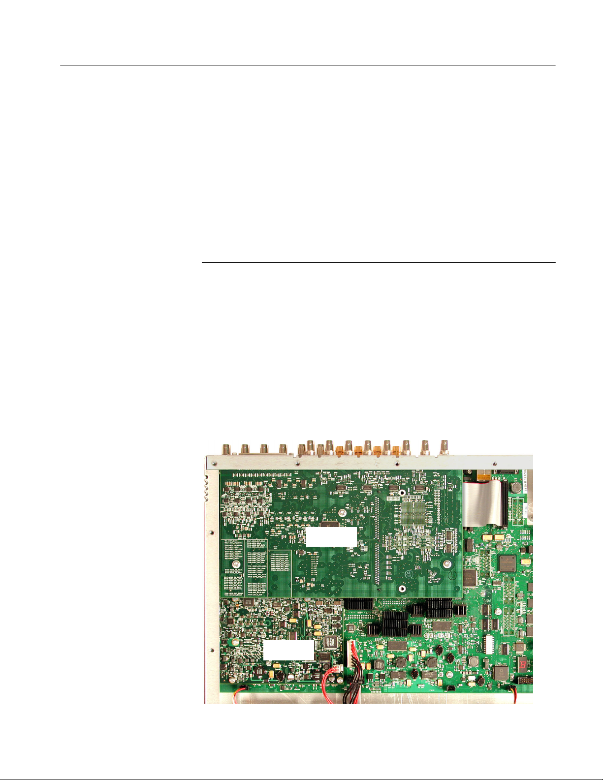
3. Inspect your instrument for an installed Audio board. If an Audio board is
installed, the AES BNC connectors are visible at the rear panel; instruments
without an Audio board have plug covers in place of the audio connectors.
Connectors present if an existing Audio
board is installed
4. If an Audio board is installed, perform the steps in the section titled Remove
Old Audio Board, on page 12 and then continue with Install Upgrade Audio
Board on page 13.
5. If your instrument does not have an Audio board installed, perform the
following steps:
a. Remove the eight plugs from the AES input holes on the rear panel.
Pinch and compress each plug from the inside while prying the plug out
from the outside of the rear panel. A flat-blade screwdriver may help pry
out the plug.
b. Remove the three Main board mounting screws as shown below.
c. Continue with Install Upgrade Audio Board on page 13.
Remove these
screws
WVR6UP, WVR70UP, and WVR7UP Upgrades
11
Page 14

Installation Instructions
Remove Old Audio Board
Perform the following steps to remove the existing Audio board in preparation
for installing the new Audio board.
1. Unplug the cable from the Audio board at J750 on the Main board.
2. Remove the three screws (T-15) that secure the old Audio board to the three
mounting posts. Screw locations are shown below.
Old Audio
Board
Remove these
screws
Unplug this
cable
Remove these
retainer posts
12
3. Remove the nut and washers that secure the eight audio BNC connectors to
the rear panel.
4. If an analog audio connector is present, use a 3/16 in. nut driver to remove
the two retainer posts that secure it to the rear panel.
WVR6UP, WVR70UP, and WVR7UP Upgrades
Page 15

Installation Instructions
5. Move the old Audio board toward the front of the instrument until the
connectors clear the rear panel, and then lift the board out of the chassis.
6. Using a 1/4 in. nut driver, remove the three mounting posts from which you
removed the screws in step 2.
Remove these
stand-off posts
Install Upgrade
Audio Board
Perform the following steps to install the new Audio board and to put it into
service. If installing option WVR6UP-DS, WVR70UP-DS, or WVR7UP-DS,
start with step 2; otherwise, start with step 1:
1. If a panel covers the analog audio input/connector hole at the rear panel,
remove the two screws that secure the panel Remove the panel by pulling it
away from the inside.
Screws and panel shown removed in
preparation for option installation
WVR6UP, WVR70UP, and WVR7UP Upgrades
13
Page 16

Installation Instructions
2. If you are installing Option DDE, perform the following sub-steps;
otherwise, skip to step 3.
a. Find the Dolby Module in your kit. In a static safe workstation only,
remove it from the static protective container.
b. As shown in the following figure, push the module into the SIMM
connector to seat it, and then push downward to rotate the module until
it is parallel to the Main board surface and the two connector latches are
locked.
Connector
latches
Connector
Plug in this
cable
3. Plug the 80-pin cable from the new audio board into its jack on the underside
of the Main board.
4. Install the three mounting posts from the kit in the locations from which you
removed the mounting screws or the mounting posts earlier. The figure
associated with step 6 on page 13 indicates the post locations. Tighten
firmly, but not excessively.
14
WVR6UP, WVR70UP, and WVR7UP Upgrades
Page 17

Installation Instructions
5. Insert the Audio board supplied with this kit into position, aligning the
mounting holes with the mounting posts and guiding the board connectors
into their holes in the rear panel:
H The mounting holes in the audio board should align with the screw holes
in the mounting posts.
H When sliding the board into place, its rear edge should be captured
between a pair of small alignment features that protrude from the rear
panel into the chassis. The board right corner should be captured
between an identical pair of alignment features at the chassis rear corner.
Cabinet protrusions
6. Secure the board to the three mounting posts with the three T-15 screws from
the kit. Tighten firmly, but not excessively.
7. From the kit, install a washer, and then a nut, to each of the BNC connectors
of the new board.
8. Plug the cable from the new Audio board into J750 on the Main board.
Plug audio cable
into J750
WVR6UP, WVR70UP, and WVR7UP Upgrades
15
Page 18

Installation Instructions
9. For all Audio boards except options WVR6UP-DS, WVR70UP-DS, and
WVR7UP-DS, install the two standoff retainers that secure the audio analog
connector to the rear panel. These screws install from the outside of the rear
panel. Tighten firmly, but not excessively.
Install stand-off retainers
Audio Connector
10. Reinstall the top cover on the instrument.
For all audio options except WVR6UP-DS, WVR70UP-DS, and WVR7UP-DS,
use the supplied 62-pin DSUB connector to attach analog-audio signals to the
instrument. Solder wires to the connector as needed to accommodate the desired
audio inputs and outputs. Refer to the WVR6100, WVR7000, and WVR7100
Waveform Rasterizers Quick Start User Manual for the connector pin assignments.
Audio signals can be connected as either balanced or unbalanced. Be sure to use
a suitable cable when you are wiring balanced audio. An example of a suitable
cable is Belden 8451, which is a shielded twisted-pair cable.
Alternatively, you can purchase an audio breakout cable (Tektronix part number
012-1688-00), which provides a two-meter cable with XLR connectors for all
twelve inputs and eight outputs.
16
WVR6UP, WVR70UP, and WVR7UP Upgrades
Page 19
EYE Board Installation (EYE and PHY Options Only)
This section describes how to install Option EYE and Option PHY only. These
options can only be installed on WVR6100 and WVR7100 instruments.
NOTE. When you install Option EYE or PHY on a WVR7100 with a serial
number of B029999 or below, you must install the new Loop-through board and
Power Supply cable which are supplied in this kit. To determine the serial
number of your instrument, refer to Serial Numbers on page 9.
When you install Option PHY on instruments that already have Option EYE
installed, you must replace the Eye board with the new board supplied in this kit.
Installation Instructions
WVR6100 and WVR7100
1. Arrange access to the top of the WVR6100 or WVR7100 (remove from rack
as needed).
2. Remove the 18 T-10 screws that secure the cabinet top cover to its chassis
and lift the cover off.
3. Use the illustration below to inspect the instrument for the presence of an
existing Audio board.
4. If an Audio board is installed, perform the Remove Old Audio Board
procedure starting on page 12.
Audio board
WVR6UP, WVR70UP, and WVR7UP Upgrades
Eye board
17
Page 20

Installation Instructions
WVR6100
Option PHY Only
5. Use the previous illustration to inspect the instrument for the presence of an
installed Eye board.
6. If an Eye board is installed, perform the following steps to remove the board:
a. As shown below, disconnect the coaxial cable from J8 on the Main
board.
b. Remove the five retaining screws from the Eye board, and then lift the
board out of the instrument.
NOTE. You can save the old Option Eye board for use in another instrument.
c. Proceed to step 13 on page 22.
18
Disconnect the coaxial cable
from J8 on Main board
Remove Eye board
retaining screws
WVR6UP, WVR70UP, and WVR7UP Upgrades
Page 21

Installation Instructions
WVR7100
Option PHY Only
7. Use the illustration on page 17 to inspect the instrument for the presence of
an installed Eye board.
8. If an Eye board is installed, perform the following steps to remove the board:
a. As shown below, disconnect the coaxial cable from J2 and J3 on the
Loop-through board.
b. Remove the five retaining screws from the Eye board, and then lift the
board out of the instrument.
NOTE. You can save the old Option Eye board for use in another instrument.
c. Proceed to step 13 on page 22.
J3J2
WVR6UP, WVR70UP, and WVR7UP Upgrades
Disconnect the two coaxial
cables connected to J2 and J3
on the Loop-through board
Remove Eye board
retaining screws
19
Page 22

Installation Instructions
WVR7100
SN B029999 and Below
Only
Perform the following steps to install the new Loop-through board.
9. To remove the old Loop-through board, perform the following steps:
a. Unplug the ribbon cable from the Loop-through board and Main board.
b. Remove the two Loop-through board mounting screws in the locations
shown below.
Loop-through
BNC connectors
Loop-through board
mounting screws
Ribbon cable
20
c. Remove the four nuts and washers that secure the four Loop-through
BNC connectors to the rear panel.
d. Back out the old Loop-through board until the connectors clear the rear
panel and lift the board out of the chassis.
WVR6UP, WVR70UP, and WVR7UP Upgrades
Page 23

Installation Instructions
10. Perform the following steps to install the new Loop-through board:
a. Insert the new Loop-through board (part number 679-9935-XX) from
this kit into position, aligning the mounting holes with the mounting
posts and guiding the four Loop-through board connectors into their
holes in the rear panel. Align the mounting holes in the new Loopthrough board with the screw holes in the two mounting posts.
b. Secure the board to the two mounting posts with the two T-15 screws
from the old Loop-through board. Tighten firmly, but not excessively.
c. From the parts retained from step 9, install a washer, and then a nut, to
each of the BNC connectors of the new board. Tighten firmly, but not
excessively.
d. Remove and discard the protective plastic plug from the connector pins
on the new Loop--through board.
e. Plug the ribbon cable from the old Loop-through board into the cable
connector pins on the new Loop-through board and to the adjacent cable
connector pins on the Main board.
WVR6UP, WVR70UP, and WVR7UP Upgrades
21
Page 24

Installation Instructions
WVR6100 and WVR7100
Perform the following steps to install the Eye board:
11. Remove the five Main board 4-40 mounting screws in the locations shown
below.
12. Install the five spacer posts (Tektronix part number 129-1604-XX) from the
kit in the locations from which you removed the mounting screws. Tighten
firmly, but not excessively.
22
Remove Main board mounting
screws and install pacer posts
in these locations
13. Insert the Eye board (Tektronix part number 664-609-XX for the WVR6100;
664-9936-XX for the WVR7100) from the kit into position, taking care to
align the Eye board mounting holes over the spacer posts. Make sure that the
connectors between the boards mate correctly. Gently press the Eye board to
seat the connectors.
14. Secure the Eye board to the five mounting posts with the five 4-40 screws
from the kit. Tighten firmly, but not excessively.
WVR6UP, WVR70UP, and WVR7UP Upgrades
Page 25

Installation Instructions
WVR6100 and WVR7100
SN B029999 and Below
Only
Perform the following steps to replace the Power Supply cable:
15. To gain adequate clearance to remove the old Power Supply cable and install
the new Power Supply cable, perform the following:
a. If present, disengage the clear plastic Power Supply shield from the
retaining slot in the fan bracket.
b. Use a 5/16-inch nut driver to loosen the two nuts that secure the fan
bracket to the base of the chassis. Loosen the nuts enough so that you
can slide the Power Supply connector under the bracket.
16. To remove the old Power Supply cable, disconnect the old cable from the
Power Supply by firmly, but carefully, pulling the cable from the Power
Supply pins on the Power Supply, and from the Power Supply pins on the
Main board.
WVR6UP, WVR70UP, and WVR7UP Upgrades
23
Page 26

Installation Instructions
17. Perform the following steps to install the new Power Supply cable:
a. Lift the fan bracket (loosened in step 15) and route the new Power
Supply cable (Tektronix part number 174-5224-XX) under the bracket
and position the cable in the rectangular cut-out in the fan bracket. Make
sure that:
H The cable end with two connectors (one seven-wire connector and
one two-wire connector) is close to the Main board.
H The cable end with one nine-wire connector is close to the Power
Supply as shown below.
b. Align the seven-wire Power Supply cable to J570 on the Main board.
Insert the cable on the board connector until the locking tab is fully
engaged (locked).
c. Align the nine-wire Power Supply cable to J2 on the Power Supply
board. Insert the cable on the board connector until the locking tab is
fully engaged (locked).
d. Connect the two-wire Power Supply cable to J3 on the Eye board. Insert
the cable on the board connector until the locking tab is fully engaged
(locked).
24
WVR6UP, WVR70UP, and WVR7UP Upgrades
Page 27

Installation Instructions
2-wire connector to
J3 on Eye board
7-wire connector to
J570 on Main board
Fan bracket
securing nuts
WVR7100 Only
Rectangular
cut-out
9-wire connector to
J2 on Power Supply
Shield
retaining slot
e. Tighten the two 5/16-inch nuts that secure the fan bracket to the base of
the chassis.
f. If present, reengage the clear plastic Power Supply shield in the retaining
slot in the fan bracket.
Perform the following steps to install the coaxial cables:
NOTE. To gain easier access to the connections on the Loop-through board, you
can disconnect the ribbon cable from the board. If you disconnect the ribbon
cable, be sure to reconnect it when you finish connecting the coaxial cables.
18. Connect one coaxial cable from the J3 connection of the Loop-through board
to the J1 connection of the Eye board.
19. Connect the remaining coaxial cable from the J2 connection of the Loopthrough board to the J2 connection of the Eye board.
20. Verify that the installed Eye board appears as shown below.
WVR6UP, WVR70UP, and WVR7UP Upgrades
25
Page 28

Installation Instructions
Connect the coaxial
cable between J2 on
Eye board and J2 on
Loop-through board.
J2 J1
Ribbon cable
Connect the coaxial
cable between J1 on
Eye board and J3 on
Loop-through board.
Loop--through board
J3J2
Eye board
26
WVR6UP, WVR70UP, and WVR7UP Upgrades
Page 29

Installation Instructions
WVR6100 Only
Perform the following steps to install the coaxial cable.
21. Connect the coaxial cable from the J1 connector on the Eye board to the
J8 connector on the Main board.
22. Verify that the installed Eye board appears as shown below.
Connect the coaxial
cable between J1
on Eye board and
J8 on Main board.
J1
J8
WVR6UP, WVR70UP, and WVR7UP Upgrades
27
Page 30

Installation Instructions
WVR6100 and WVR7100
Perform the following steps to complete the hardware installation:
23. Use a 5/16” open-end wrench to tighten the coaxial cable connectors firmly,
but not excessively.
24. If your instrument had an Audio board installed, perform the Install Upgrade
Audio Board procedure starting on page 13 to reinstall the board.
25. If you installed an Audio board, before replacing the top cover, check that
your instrument appears as shown below.
26. Replace the top cover.
WVR6100 and WVR7100
Option PHY Only
28
27. After installing the Eye board, go to to page 29 and perform the steps in the
Option Activation section.
WVR6UP, WVR70UP, and WVR7UP Upgrades
Page 31

Option Activation
Installation Instructions
Option-SD
Option-DD
Option-DDE
Option-PHY
For these options only, you must activate the option before you can use it.
Perform the following steps to activate the option:
NOTE. This kit provides an option key based on the instrument serial number
that you provided to Tektronix when you ordered this kit. The kit option key
enables your new option(s) only on the rasterizer having the serial number that
you provided.
1. Make sure that the product to be activated is networked to a computer. See
your User Technical Reference if you need help in doing so. (You can access
this manual on the Documents CD that shipped with this kit.)
2. Start the Web browser, and set its address to that of the rasterizer to navigate
to the Remote Interface page. See Remote Communications in your User
T echnical Reference if you need help in doing so. (Y ou can access this
manual on the Documents CD that shipped with this kit.)
3. ClickontheInstrument Options to navigate to the Active Options page,
and enter the key supplied with your kit.
4. Click the Submit button.
A pop-up message follows a successful upgrade, and the Active Options
page reflects the newly installed option along with those already present.
Refresh the page if the installed option is not displayed.
5. Refer to Usage on the following page for information on using your upgrade.
Option-DS
Option-AD
Option-EYE
WVR6UP, WVR70UP, and WVR7UP Upgrades
For these options only, no activation is required and your WVR upgrade is
complete. Your instrument automatically detects the upgrade and you can use the
new features that it provides.
Refer to Usage on the following page for information on using your upgrade.
29
Page 32

Installation Instructions
Usage
To use your upgraded instrument, note that the following support is available:
H The System Upgrade that you just performed installed the current online
help, which supports all current product options and features.
H The Documents CD provides a PDF copy of the updated Quick Start User
Manual,theUser Technical Reference, and other documents that support all
currently available options. You can access these documents using the
Documents Browser on the CD or you can navigate to the PDFs and print
them.
H The latest versions of both the product software and the documentation are
available at www.tektronix.com.
g End of document g
30
WVR6UP, WVR70UP, and WVR7UP Upgrades
 Loading...