

Page 1

xx
WVR7200
Waveform Rasterizers
ZZZ
Installation and Safety
Instructions
*P071302400*
071-3024-00
Page 2

Page 3

xx
WVR7200
Waveform Rasterizers
ZZZ
Installation and Safety
Instructions
www.tektronix.com
071-3024-00
Page 4

Copyright © Tektronix. All rights reserved. Licensed software products are owned by Tektronix or its subsidiaries
or suppliers, and are protected by national copyright laws and international treaty provisions.
Tektronix products are covered by U.S. and foreign patents, issued and pending. Information in this publication
supersedes that in all previously published material. Specifica tions and price change privileges reserved.
TEKTRONIX and TEK are registered trademarks of Tektronix, Inc.
Contacting Tektronix
Tektronix, Inc.
14150 SW Karl Braun Drive
P.O. B o x 5 0 0
Beaverto
USA
For product information, sales, service, and technical support:
n, OR 97077
In North America, call 1-800-833-9200.
Worl dwid e, v isit www.tektronix.com to find contacts in your area.
Page 5

Table of Contents
Preface ............................................................................................................... 1
Documentation ................................................................................................. 1
General Safety Summary .......................................................................................... 2
Compliance Information........................................................................................... 4
EMC Compliance............................. ................................ ................................ . 4
Safety Compliance............................................................................................. 5
Environmental Considerations ........................................ ................................ ....... 6
Operating Requirements ........................................................................................... 7
Electrical Ratings .............................................................................................. 7
Environmental Ratings ........................................................................................ 8
Physical Specifications........................................................................................ 8
Rear-Panel Connectors............................................................................................. 9
Input and Output Connectors.... ................................ ................................ ............ 10
Basic Installation Procedure...................................... ................................ ................ 16
Before Installation ............................................................................................ 17
Installing in a Video System . ..... . ..... . ..... . .... . . .... . ..... . ..... . ..... . ..... . .... . ..... . ..... . ..... . ... . 19
Power-On and Power-Off Procedure ............................................................................ 22
ont-Panel Controls ............ ................................ .................................. ................ 23
Fr
はじめに.................................................................................................. 26
マニュアル ........................................................................................... 26
安全にご使用いただくために .......................................................................... 27
適合性に関する情報.................................................................................... 29
EMC 適合性......................................................................................... 29
安全性 ............................................................................................... 30
環境に関する考慮事項 ............................................................................ 31
動作の要件 .............................................................................................. 33
電気定格 ............................................................................................ 33
環境要件 ............................................................................................ 34
物理仕様 ............................................................................................ 34
リア・パネル・コネクタ.................................................................................... 35
入力/出力コネクタ ................................................................................ 36
基本的な設置手順 ...................................................................................... 43
設置の前に .......................................................................................... 44
ビデオ・システムへの設置.......................................................................... 46
電源投入、電源遮断の手順............................................................................ 48
フロント・パネル・コントロール .......................................................................... 49
前言 ...................................................................................................... 53
文档 .................................................................................................. 53
WVR7200 Installation and Safety Instructions i
Page 6

Table of Contents
常规安全概要 ........................................................................................... 54
符合性信息 .............................................................................................. 56
EMC 符合性 .......................................................................................... 56
安全符合性.......................................................................................... 57
环境注意事项....................................................................................... 58
操作要求................................................................................................. 59
电源额定值.......................................................................................... 59
环境额定值.......................................................................................... 60
物理技术规格....................................................................................... 60
后面板连接器 ........................................................................................... 61
输入和输出连接器 ................................................................................. 62
基本安装步骤 ........................................................................................... 68
安装之前 ............................................................................................ 69
在视频系统中安装 ................................................................................. 71
开机和关机步骤 ........................................................................................ 73
前面板控件 .............................................................................................. 74
ii WVR7200 Installation and Safety Instructions
Page 7

Preface
This document contains the following information:
Important safety precautions to avoid injury and prevent damage to this
product or any products connected to it
EMC (electromagnetic compliance), safety, and environmental standards
with which the instrument complies
Voltage, power, and environmental requirements to use the product
Installation procedure
Power-on and power-off procedure
Front-p
anel and rear-panel features
Documentation
The fol
product and shows where you can find it: in a printed manual, on the product
documentation CD-ROM, or on the Tektronix Web site at www.tektronix.com.
Table 1: Product documentation
Item Purpose Location
Installation and Safety Instructions
(this manual)
User Manual
Online Help
Specifications and Performance
Verification Technical R eference
WFM and WVR Series
Management Information
Database (MIB) Programmer
Manual
Service Manual Provides information about adjustments, repair, and
Provides safety and compliance information with
hardware installation instructions to present the
associated safety warnings. This manual is available
in English, Japanese, and Simplified Chinese.
Provides operation and application information.
In-depth instrument operation and UI help.
Specifications and procedures for checking instrument
performance.
SNMP command reference for remotely controlling the
instrument.
replaceable parts.
lowing table lists some of the documentation that is available for this
Printed manual and also
available in electronic format
at www.tektronix.com/manuals
Product Documentation
CD and available at
www.tektronix.com/manuals
On the instrument
Product Documentation
CD and available at
www.tektronix.com/manuals
Product Documentation
CD and available at
www.tektronix.com/manuals
Available at
www.tektronix.com/manuals
WVR7200 Installation and Safety Instructions 1
Page 8

General Safety Summary
General Safet
To Avoid Fire or Personal
Injury
ySummary
Review the fo
this product or any products connected to it.
To avoid potential hazards, use this product only as specified.
Only qualified personnel should perform ser vice procedures.
Use Proper Power Cord. Use only the power cord specified for this product and
certified for the country of use.
Ground the Product. This product is grounded through the grounding conductor
of the power cord. To avoid electric shock, the grounding conductor must be
connected to earth ground. Before making connections to the input or output
terminals of the product, ensure that the product is properly grounded.
Observe All Terminal Ratings. To avo id fire or shock hazard, observe all ratings
and markings on the product. Consult the product manual for further ratings
information before making connections to the product.
Do not apply a potential to a ny terminal, including the common terminal, that
exceeds the maximum rating of that terminal.
llowing safety precautions to avoid injury and prevent damage to
Power Disconnect. The power cord disconnects the product from the power
source. Do not block the power cord; it must remain accessible to the user at
all times.
Do Not Operate Without Covers. Do not operate this product with covers or
panels removed.
Do Not Operate With Suspected Failures. If you suspect that there is damage to
this product, have it inspected by qualified service personnel.
Avoid Exposed Circuitry. Do not touch exposed connections and components
when powe r is present.
Use Proper AC Adapter. Use only the AC adapter specified for this product.
Do Not Operate in Wet/Damp Conditions.
Do Not Operate in an Explosive Atmosphere.
Keep Product Surfaces Clean and Dry.
Provide Proper Ventilation. Refer to the manual's installation instructions for
details on installing the product so it has proper ventilation.
2 WVR7200 Installation and Safety Instructions
Page 9

General Safety Summary
Terms in this Manual
Symbols and Terms on the
Product
These terms may
WAR NI NG . Warning s tatements identify conditions or practices that could result
in injury or loss of life.
CAUTION. Caution statements identify conditions or practices that could result in
damage to this product or other property.
These terms may appear on the product:
DANGER in
the marking.
WARNING
read the marking.
CAUTIO
The following symbol(s) may appear on the product:
appear in this manual:
dicates an injury hazard immediately accessible as you read
indicates an injury hazard not immediately accessible as you
N indicates a hazard to property including the product.
WVR7200 Installation and Safety Instructions 3
Page 10

Compliance Information
Compliance In
EMC Compliance
EC Declaration of
Conformity – EMC
formation
This section
environmental standards with which the instrument complies.
Meets intent of Directive 2004/108/EC for Electromagnetic Compatibility.
Compliance was demonstrated to the following specifications as listed in the
Official Journal of the European Communities:
EN 55103:1996. Product family standard for audio, video, audio-visual and
entertainment lighting control apparatus for professional use.
Environment E2 – commercial and light industrial
Part 1 Emission
Part 2 Immunity
lists the EMC (electromagnetic compliance), safety, and
1,2
EN 55022:1987. Class B radiated and conducted emissions
EN 55103-1:1996 Annex A. Radiated magnetic field emissions
IEC 61000-4-2:2001. Electrostatic discharge immunity
IEC 61000-4-3:2006. RF electromagnetic field immunity
IEC 61000-4-4:2004. Electrical fast transient / burst immunity
IEC 61000-4-5:2005. Power line surge immunity
IEC 61000-4-6:2003. Conducted RF Immunity
IEC 61000-4-11:2004. Voltage dips and interruptions immunity
EN 55103-2:1996 Annex A Radiated magnetic field immunity
1
To ensure compliance with the EMC standards listed here, high-quality shielded interface cables should be used.
2
Inrush current: 8 A peak.
EN 61000-3-2:2006. AC power line harmonic emissions
EN 61000-3-3:1995. Voltage changes, fluctuations, and flicker
European Contact.
Tektronix UK, Ltd.
Western Peninsula
Western Road
Bracknell, RG12 1RF, United Kingdom
4 WVR7200 Installation and Safety Instructions
Page 11

Compliance Information
Australia / New Zealand
Declaration of
Conformity – EMC
Safety Compliance
EC Declaration o f
Conformity – Low Voltage
U.S. Natio nally Recognized
Testing Laboratory Listing
Canadian Certification
Complies with t
following standard, in accordance with ACMA:
EN 55022:1987
with EN 55103-1:1996.
Compliance was demonstrated to the following specification as listed in the
Official Journal of the European Communities:
Low Voltage Directive 2006/95/EC.
EN 61010-1: 2001. Safety requirements for electrical equipment for
measurement control and laboratory use.
UL 61010
equipment.
CAN/CSA-C22.2 No. 61010-1:2004. Safety requirements for electrical
equipm
he EMC provision of the Radiocommunications Act per the
. Radiated and conducted emissions, Class B, in accordance
-1:2004, 2
ent for measurement, control, and laboratory use. Part 1.
nd
Edition. Standard for electrical measuring and test
Additional Compliances
pment Type
Equi
Safety Class
Pollution Degree
cription
Des
IEC 61010-1: 2001. Safety requirements for electrical equipment for
measurement, control, and laboratory use.
Test and measuring equipment.
Class1–groundedproduct.
A measure of the contaminants that could occur in the environment around
within a product. Typically the internal environment inside a product is
and
considered to be the same as the external. Products should be used only in the
environment for which they are rated.
Pollution Degree 1. No pollution or only dry, nonconductive pollution occurs.
Products in this category are generally encapsulated, hermetically sealed, or
located in clean rooms.
Pollution Degree 2. Normally only dry, nonconductive pollution occurs.
Occasionally a temporary conductivity that is caused by condensation must
be expected. This location is a typical office/home environment. Temporary
condensation occurs only when the product is out of service.
WVR7200 Installation and Safety Instructions 5
Page 12

Compliance Information
Pollution Degree
Environme
Product End-of-Life
Pollution Degr
that becomes conductive due to condensation. These are sheltered locations
where neither temperature nor humidity is controlled. The area is protected
from direct sunshine, rain, or direct wind.
Pollution Degree 4. Pollution that generates persistent conductivity through
conductive dust, rain, o r snow. Typical outdoor locations.
Pollution Degree 2 (as defined in IEC 61010-1). Note: Rated for indoor use only.
ntal Considerations
This section provides information about the environmental impact of the product.
Observe the following guidelines when recycling an instrument or component:
Handling
Equipment Recycling.
Production of this equipment required the extraction and use of natural resources.
The equipment may contain substances that could be harmful to the environment
or human health if improperly handled at the product’s end of life. In order to avoid
release of such substances into the environment and to reduce the use of natural
rces, we encourage you to recycle this product in an appropriate system that
resou
will ensure that most of the materials are reused or recycled appropriately.
ee 3. Conductive pollution, or dry, nonconductive pollution
Restriction of Hazardous
Substances
This symbol indicates that this product complies with the applicable European
Union requirements according to Directives 2002/96/EC and 2006/66/EC
on waste electrical and electronic equipment (WEEE) and batteries. For
information about recycling options, c heck the Support/Service section of the
Tektronix Web site (www.tektronix.com).
Perchlorate Materials. This product contains one or more type CR lithium
batteries. According to the state of California, CR lithium batteries are
classified as perchlorate materials and require special handling. See
www.dtsc.ca.gov/hazardouswaste/perchlorate for additional information.
This product has been classified as Monitoring and Control equipment, and is
outside the scope of the 2002/95/EC RoHS Directive.
6 WVR7200 Installation and Safety Instructions
Page 13
Operating Requirements
Operating Req
Electrical Ratings
Power Requirements
uirements
This section
product safely and correctly. Refer to the complete product specifications for
additional information.
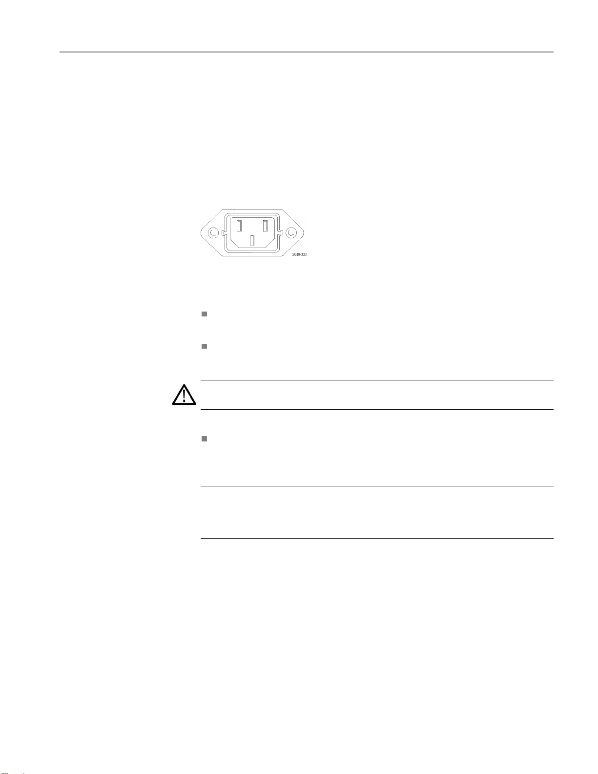
Power connector
The instrument has the following power requirements:
A single-phase power source with one current-carrying conductor at or near
earth-ground (the neutral conductor).
The power source frequency must be 50 or 60 Hz, and a operating voltage
range must be from 100 to 240 VAC, continuous.
provides the speci fi cations that you need to know to operate your
WAR NI NG . Toreduceriskoffire and shock, ensure the mains supply voltage
ations do not exceed 10% of the operating voltage range.
fluctu
Systems with both current-carrying conductors live with respect to ground
ch as phase-to-phase in multiphase systems) are not recommended as
(su
power sources.
NOTE. Only the line conductor is fused for over-current protection. The fuse is
internal and not user replaceable. Do not attempt to replace the fuse. If you
suspect the fuse has blown, return the unit to an authorized service center for
repair.
WVR7200 Installation and Safety Instructions 7
Page 14

Operating Requirements
Environmental Ratings
Table 2: Environmental performance
Category Standards or description
Temperature
Humidity
Altitude
Cooling The intake air vents in the front of the instrument must not be blocked and the rear exhaust
Operating 0 °C to +40 °C
Non Operating –40 °C to +75 °C
Operating 20% to 80% relative humidity (% RH) at up to +40 °C, non-condensing
Non Operating 5% to 90% RH (relative humidity) at up to +60 °C, non-condensing
Operating Up to 9,842 feet (3,000 meters)
Non Operating Up to 40,000 feet (12,192 meters)
quires at least 1 inch of clearance. No clearance is required above or below the
vents re
instrument.
Physic
al Specifications
Table 3: Physical characteristics
cteristic
Chara
Dimensions
Weight
Height
Width
Depth
Net
ipping
Sh
Cleaning
ard
Stand
nches (4.37 centimeters)
1.72 i
ches (48.26 centimeters)
19 in
25 inches (51.44 centimeters) (Not including cables)
20.
pounds (4.31 kilograms), maximum
9.5
pounds (8.62 kilograms), approximate
19
t required for the safe operation of the instrument. However, if you wish to
No
perform routine cleaning on the exterior of the instrument, refer to the user manual
on the Product Documentation CD that was shipped with your instrument.
8 WVR7200 Installation and Safety Instructions
Page 15

Rear-Panel Connectors
Rear-Panel Co
nnectors
The followin
rear-panel inputs are arranged in Slot 1 or Slot 2. Although these slots are not
labeled as such on the rear-panel, the center section corresponds to the Slot 1 Input
buttons on the front panel and usually contains the SDI or EYE inputs. The right
section of the rear panel corresponds to the Slot 2 Input buttons on the front panel,
and will contain the composite inputs, if present. (See Figure 4 on page 23.)
g figure shows the rear-panel with optional connectors. The
Figure 1: Rear-panel
WVR7200 Installation and Safety Instructions 9
Page 16

Rear-Panel Connectors
Input and Outp
Video Connectors
ut Connectors
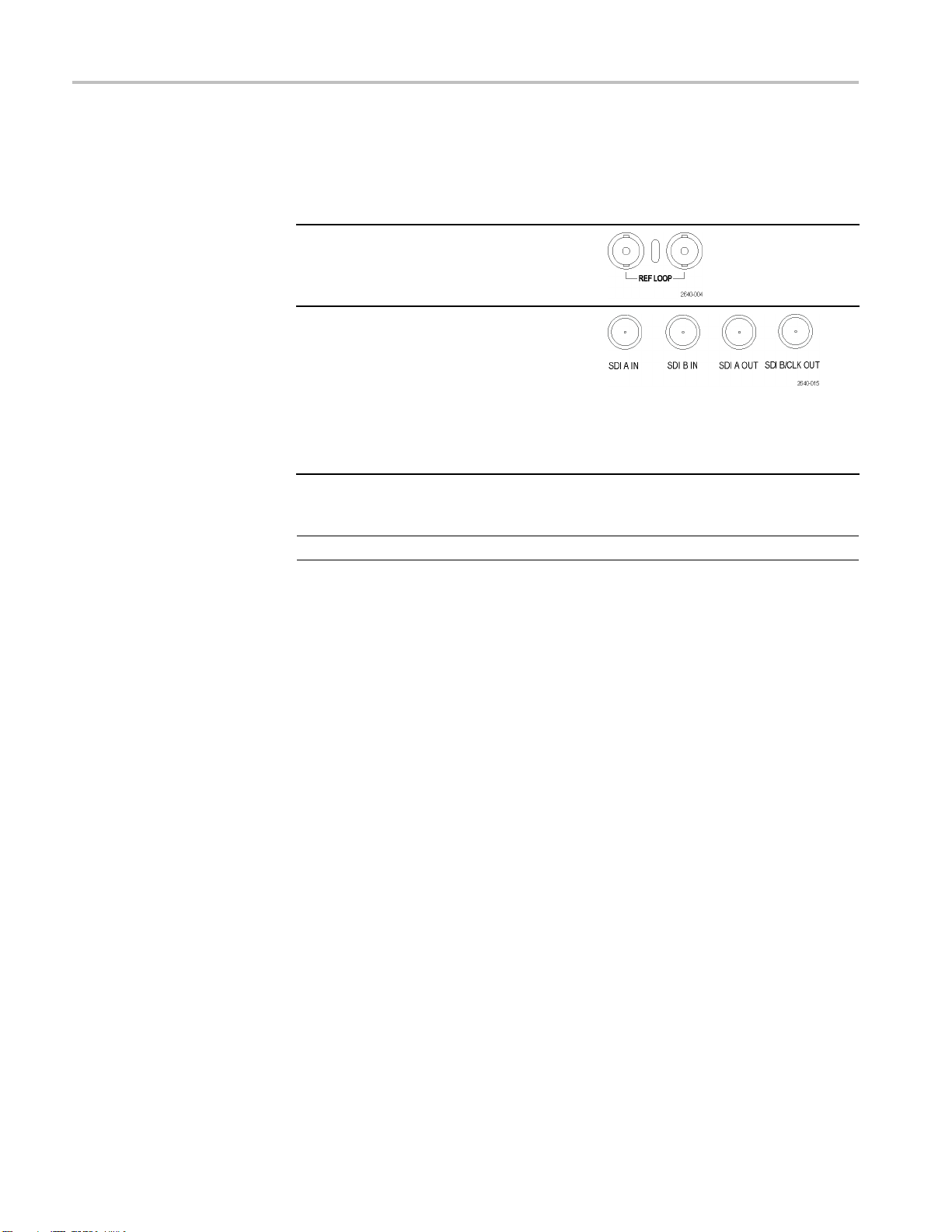
SDI inputs are self-terminating inputs.
Inputs
REF Loop. A synchronization input. The
input signa
composite video, or analog tri-level for HD.
Requires termination.
SDI A IN. Th
input.
SDI B IN. The digital B component serial digital
input.
SDI A OUT. Reclocked output of the SDI A input.
SDI B / CLK OUT. Reclocked output of the
SDI B inpu
instruments with Option PHY3.
Reference and Composite inputs are passive loop inputs.
NOTE. External termination for reference and composite inputs is required.
Connectors
l can be analog black burst, analog
e digital A component serial digital
Options PHY3
t. Also a recovered clock output for
10 WVR7200 Installation and Safety Instructions
Page 17

Rear-Panel Connectors
Inputs
CMPST A. The c omposite A analog input.
CMPST B. The c omposite B analog input.
SDI O UT. Can b
Loop Out, or Test Signal
1
Test Signal
e selected to output Pixmon,
1
.
is available for Option GEN only.
AES A/B Connectors
Inputs Connectors
These BNC connectors support AES audio
inputs.
Input A fo
Input A for AES channels 3 and 4
Input A for AES channels 5 and 6
Input A f
Default input B for AES channels 1 and 2
Default input B for AES channels 3 and 4
Default
Default input B for AES channels 7 and 8
1
r AES channels 1 and 2
Options AD and DPE
or AES channels 7 and 8
1
1
input B for AES channels 5 and 6
TheAESBconnectorscanbeconfigured to output embedded audio channels, decoded Dolby, or the AES A inputs.
1
1
Connectors
Analog
Input/Output
Connector
The Analog I/O connector is used to receive and send analog signals. The Analog
I/O connector is a 62-pin, D-subminiature connector. Pin assignments and pin
names are listed in the following figure and table.
ION. Use care when connecting the Analog Audio Output. Refer to the
CAUT
instrument specifications to ensure that the Audio Load and Output Power meet
specifications. Exceeding Analog Audio Output Power may result in damage
to the instrument.
Option AD Input./Output connector
WVR7200 Installation and Safety Instructions 11
Page 18

Rear-Panel Connectors
Pin Description
1 ANALOG_INPU
2 ANALOG_INPU
3 ANALOG_INP
4 ANALOG_IN
5 ANALOG_IN
6 ANALOG_I
7 ANALOG_
8 ANALOG_
9ANALOG
10 ANAL
11 ANAL
12 ANA
13 GND
14 AN
15 AN
16 A
17
18
1
2
21 ANALO G_OUTP UT_8_P Balanced differential analog audio output- Ch. 8, positive.
22 ANALOG_INPUT_A1_N Balanced differential analog audio input- Ch. 1, line A, negative.
23 ANALOG_INPUT_B1_N Balanced differential analog audio input- Ch. 1, line B, negative.
24 ANALOG_INPUT_A2_N Balanced differential analog audio input- Ch. 2, line A, negative.
25 ANALOG_INPUT_B2_N Balanced differential analog audio input- Ch. 2, line B, negative.
26 ANALOG_INPUT_A3_N Balanced differential analog audio input- Ch. 3, line A, negative.
27 ANALOG_INPUT_B3_N Balanced differential analog audio input- Ch. 3, line B, negative.
28 ANALOG_INPUT_A4_N Balanced differential analog audio input- Ch. 4, line A, negative.
29 ANALOG_INPUT_B4_N Balanced differential analog audio input- Ch. 4, line B, negative.
30 ANALOG_INPUT_A5_N Balanced differential analog audio input- Ch. 5, line A, negative.
31 ANALOG_INPUT_B5_N Balanced differential analog audio input- Ch. 5, line B, negative.
32 ANALOG_INPUT_A6_N Balanced differential analog audio input- Ch. 6, line A, negative.
33 ANALOG_INPUT_B6_N Balanced differential analog audio input- Ch. 6, line B, negative.
34 GND
35 ANALOG_OUTPUT_1_N Balanced differential analog audio output- Ch. 1, negative.
36 ANALOG_OUTPUT_2_N Balanced differential analog audio output- Ch. 2, negative.
37 ANALOG_OUTPUT_3_N Balanced differential analog audio output- Ch. 3, negative.
38 ANALOG_OUTPUT_4_N Balanced differential analog audio output- Ch. 4, negative.
OG_INPUT_B5_P
OG_INPUT_A6_P
LOG_INPUT_B6_P
ALOG_OUTPUT_1_P
ALOG_OUTPUT_2_P
NALOG_OUTPUT_3_P
ANALOG_OUTPUT_4_P
ANALOG_OUTPUT_5_P
9 ANALOG_OUTPUT_6_P
0 ANALOG_OUTPUT_7_P
T_A1_P
T_B1_P
UT_A2_P
PUT_B2_P
PUT_A3_P
NPUT_B3_P
INPUT_A4_P
INPUT_B4_P
_INPUT_A5_P
Balanced diff
Balanced diff
Balanced dif
Balanced di
Balanced di
Balanced d
Balanced
Balanced
Balance
Balanc
Balanc
Balan
nced differential analog audio output- Ch. 1, positive.
Bala
nced differential analog audio output- Ch. 2, positive.
Bala
anced differential analog audio output- Ch. 3, positive.
Bal
lanced differential analog audio output- Ch. 4, positive.
Ba
lanced differential analog audio output- Ch. 5, positive.
Ba
alanced differential analog audio output- Ch. 6, positive.
B
alanced differential analog audio output- Ch. 7, positive.
B
erential analog audio input- Ch. 1, line A, positive.
erential analog audio input- Ch. 1, line B, positive.
ferential analog audio input- Ch. 2, line A, positive.
fferential analog audio input- Ch. 2, line B, positive.
fferential analog audio input- Ch. 3, line A, positive.
ifferential analog audio input- Ch. 3, line B, positive.
differential analog audio i nput- Ch. 4, line A, positive.
differential analog audio i nput- Ch. 4, line B, positive.
d differential analog audio input- Ch. 5, line A, positive.
ed differential analog audio input- Ch. 5, line B, positive.
ed differential analog audio input- Ch. 6, line A, positive.
ced differential analog audio input- Ch. 6, line B, positive.
12 WVR7200 Installation and Safety Instructions
Page 19

Pin Description
39 ANALOG_OUT
40 ANALOG_OUT
41 ANALOG_OU
42 ANALOG_O
43– 62 No connection.
PUT_5_N
PUT_6_N
TPUT_7_N
UTPUT_8_N
Balanced diff
Balanced diff
Balanced dif
Balanced di
ferential analog audio output- Ch. 7, negative.
fferential analog audio output- Ch. 8, negative.
Rear-Panel Connectors
erential analog audio output- Ch. 5, negative.
erential analog audio output- Ch. 6, negative.
EXT DISPLAY Connector
Pin Assignment
PIX M ON Connector Pin
Assignment
This is the external display monitor output. The display resolution is 1024 x
768. The output supports DVI monitors directly and analog PC (RGB) monitors
with the use of a DVI-I to VGA adapter. The EXT DISPLAY connector is a
DVI-I connector with socket contacts.
EXT DISPLAY connector
This is the video picture output. The output is compatible with standard analog
PC monitors, either CRT or LCD-based. The PIX MON connector is a 15-pin
D-type connector with socket contacts.
PIX MON connector
Pin Pin name
1 Red Video
2
3 Blue Video
4 Not connected
5
6
7
8
9
10
11
12
13
Green Video
Ground
Red Ground
Green Ground
Blue Ground
Not Connected
Not Connected
Not Connected
Not Connected
Horizontal Sync
WVR7200 Installation and Safety Instructions 13
Page 20

Rear-Panel Connectors
REMOTE Connector Pin
Assignment
14
15
The REMOTE connector interface uses ground closures for remote control and
indicating to external equipment when alarms have occurred. The input of LTC is
Vertical Sync
Not Connected
through the REMOTE connector. The REMOTE connector is a 15-pin D-type
connector with socket contacts
NOTE. For m
ore information on Preset recall, refer to the Technical Reference
manual on the Product Documentation CD that was shipped with your instrument.
Remote c
Characteristic Pin out Preset functions
Connector Pin Assignments
1GND(In)
2 Reserved (I/O)
3 Reser
4 Reserved (In)
5 Reserved (In)
6GND(
7 Time Code Positive (LTC In)
8 Time Code Negative (LTC In)
9Gro
10 Preset 1 (In)
11 Preset 2 (In)
12 P
13 Preset 4 (In)
14 Preset 5 (In)
15 P
onnector preset functions.
ved (I/O)
In)
und Closure (Alarm Out)
reset 3 (In)
reset 6 (In)
Hex Binary
Pins 15,
14, 13,
12, 11,
10
F 11111
E XX1110 Preset 1
D XX1101 Preset 2
C
B XX1011 Preset 3
A XX1010
9 XX1001
8 XX1000 Preset 8
7
6X
5
4 XX0100 Preset 4
3 XX0011 Preset 3
2 XX0010 Preset 2
1 XX0001 Preset 1
0 XX0000 Unused
1
XX1100
XX0111 Preset 4 Preset 7
X0110
XX0101 Preset 5
Direct
mode
selection
none
Encoded
mode
selection
ion
No act
CMPST
TA
CMPS
SDI B
A
SDI
nnel B
Cha
annel A
Ch
reset 6
P
B
14 WVR7200 Installation and Safety Instructions
Page 21

Rear-Panel Connectors
Ethernet Connector
The instrument
connector is a standard RJ-45 connector.
Ethernet connector
provides a 10/100/1000 BaseT Ethernet interface. The Ethernet
WVR7200 Installation and Safety Instructions 15
Page 22

Basic Installation Procedure
Basic Installation Procedure
Your instrument is shipped in a fully enclosed metal chassis. You can operate the
instrument in the provided chassis or install the chassis in a standard, 19-inch
equipment ra
To install your instrument in a rack, follow the instructions that are included with
the optiona
cooling and clearance requirements. (See page 8, Environmental Ratings.)
CAUTION. Do not install this instrument in any cabinet; attempting to do so can
damage the instrument and the cabinet.
If you need to install your instrument in a custom application, such as a console,
be sure to provide adequate airflow and ensure that the intake air to the side vents
do not exceed 40 °C. Do not block or restrict the ventilating holes. Refer to the
Environmental Ratings section for cooling and clearance requirements. (See
page 8, E
ck.
l accessory kit. Also refer to the Environmental Ratings section for
nvironmental Ratings.)
When installing in a custom application, use the Rack Adapter clearances.
ON. To prevent risk of fire, adequate airflow must be maintained. Failure
CAUTI
to provide adequate airflow to the instrument could cause the instrument to
shut down. Inadequate airflow includes placing the instrument in any small,
enclosed room that lacks a ventilation system, such as a closet. If the airflow is
restricted or blocked and the instrument does not shut down, the instrument c ould
be permanently damaged and increases the risk of fire.
16 WVR7200 Installation and Safety Instructions
Page 23

Basic Installation Procedure
Before Instal
lation
Unpack the instrument and check that you have received all of the items listed
as standard accessorie s. You may want to save the shipping carton and packing
ncluding the anti-static bag) in case you need to ship the instrument.
Accessories
materials (i
The following table shows which items are shipped with your instrument
(Standard) and which items are available on the Tektronix Web site only
(Optional
). Check our Web site (www.tektronix.com) for the most current
information on accessories.
Accessory Standard Optional Tektronix part number
WVR7200 Waveform Rasterizers Installation and Safety Instructions
(English, Japanese, Simplified Chinese)
WVR7200 Waveform Rasterizers Product Documentation CD
This CD contains the following documents in PDF format. (All documents
are in English unless noted otherwise):
WVR7200 Waveform Rasterizers User Manual
WVR7200 Waveform Rasterizers Specifications and Performance
Verification Technical Reference
WFM and WVR Series Management Information Database (MIB)
Programmer Manual
WVR7200, WVR8200 and WVR8300 Waveform Rasterizers System
Integration Instructions
WVR7200 Waveform Rasterizers Release Notes
WVR7200 Waveform Rasterizers Declassification and Security Instructions
WVR7200 Waveform Rasterizers S ervice Manual
8RFP Option Remote Front Panel Instructions
WVR
Power Cord
071-3024-XX
063-4428-XX
077-0668-XX
077-0670-XX
071-0261-XX
077-0392-XX
077-0674-XX
077-0672-XX
077-0676-XX
071-2804-XX
Not applicable
NOTE. See the International Power Cords list that follows this table for
the type of power cord included with your instrument.
WVR7200 Installation and Safety Instructions 17
Page 24

Basic Installation Procedure
International
power cords. Your instrument was shipped with one of the following
power cord options. Power cords for use in North America are UL listed and CSA
certified. Cords for use in areas other than North America are approved by at least
one authority acceptable in the country to which the product is shipped.
Opt. A0 – North America power
Opt. A1 – Universal EUR power
Opt. A2 – Uni
ted Kingdom power
Opt. A3 – Australia power
Opt. A4 – 240 V, North America power
Opt. A5 – Switzerland power
Opt. A6 – Japan power
Opt. A10 – China power
1
9
Opt. A9
1
When ordering the A99 option, it is the responsibility of the end user to ensure that a certified power cord, for the
y or region it is installed, is used with this instrument.
countr
–NopowercordorACadapter
CAUTION. To reduce risk of fire and shock, use the certified power cord provided
with the product.
18 WVR7200 Installation and Safety Instructions
Page 25

Basic Installation Procedure
Installing in
For Monitori
Bit Stream of a Serial
ng the Video
a Video System
The instrument can operate almost anywhere in the distribution system. The
following diagrams for serial digital systems and for the analog composite inputs.
Route the incoming serial signal into one of the instrument SDI inputs.
Receiver
Figure
2: Options PHY3 and 3G
NOTE. See the Specifications and Performance Verification manual on the
Product Documentation CD for maximum-allowed cable lengths.
WVR7200 Installation and Safety Instructions 19
Page 26

Basic Installation Procedure
For Monitoring Composite
Signals
Figure 3: Option CPS
Connect your so
the rear-panel.
urces to the CMPST A or CMPST B loop-through inputs on
Line Termination
Your instrument uses passive loop-through, analog reference and composite video
inputs. Accordingly, the loop-through inputs must be terminated externally.
It is important that this external termination meets accuracy and return loss
requirements.
If the instrument is installed to monitor an operating link, the destination receiver
and the connecting cable serve as the termination. This monitoring connection
ks the performance of the entire path. The return loss of the instrument is
chec
sufficiently high that, in most cases, the destination receiver sets the system return
loss.
In cases where the instrument is placed at the end of a link, a BNC termination
must be installed on one side of the loop-through input. The termination must
be 75 Ω and DC coupled (good return loss extends to DC). An appropriate
termination is Tektronix part number 011-0102-00; this is a 75 Ω, End-of-Line
termination.
Return loss from composite signals must be >40 dB from DC to 6 MHz.
20 WVR7200 Installation and Safety Instructions
Page 27

Basic Installation Procedure
Compatibility of BNC
Center Pins
Most BNC connec
standard center pin. Some laboratory 75 Ω BNCconnectorsuseasmaller
diameter center pin. The BNC connectors on the instrument are designed to work
with the 50 Ω standard (large diameter) center pins.
NOTE. Do not use connectors or terminators with non-standard sized center pins.
Using pins that have a smaller diameter could cause intermittent connections.
tors for video equipment, whether 50 Ω or 75 Ω,usea50Ω
WVR7200 Installation and Safety Instructions 21
Page 28

Power-On and Power-Off Procedure
Power-On and P
AC Power Requirements
Power-On
ower-Off Procedure
This instrum
conductor at or near earth ground. The line conductor is fused for over-current
protection. A protective ground connection through the grounding conductor in
the power cord is essential for safe operation.
The instrument operates from an AC line frequency of 50 or 60 Hz, over the range
of 100-240 Volts, without the need for configuration, except the power cord.
(See page 18, International power cords.) The typical power draw is 140 Watts.
Refer to the WVR7200 Specifications and Performance Verification Technical
Reference on the Product Documentation CD for additional information on power
and envi
1. Connect the supplied power cord to the rear-panel power connector.
2. Press the power button on the instrument front-panel and the instrument will
turn on.
NOTE. The Standby button on the front-panel does not disconnect mains power.
Only t
ent operates from a single-phase power source with the neutral
ronmental requirements.
he power cord at the rear of the product can disconnect mains power.
Pow
er-Off
Ensure that the power cord is accessible when the product is operating.
1. Press the power button on the instrument front-panel to turn the instrument off.
2. To remove power completely, disconnect the power cord from the rear-panel
of the instrument.
22 WVR7200 Installation and Safety Instructions
Page 29
Front-Panel Controls
Front-Panel C
Layout and
Usage
ontrols
NOTE. Some of the controls that this section covers are option dependant. For a
list of the options that are installed on your instrument, press the CONFIG button.
In the con figuration menu, select the Utilities submenu. The View Instruments
Options entry lists the options installed on your instrument.
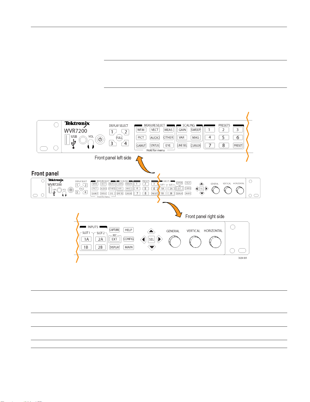
The front-panel elements shown below are described in the table that follows.
Figure 4: Front-panel
Control Element or Group Description
Power button
DISPLAY SELECT buttons Each numbered display select button corresponds to one of the four tiles of the display screen;
MEASURE SELECT buttons WFM, PICT, GAMUT, V ECT, A UDIO, STATUS, MEAS, OTHER, and EYE to select
WFM
WVR7200 Installation and Safety Instructions 23
Press to power on or off. The power button also indicates when the instrument is detecting a
ult (such as a fan failure) when it is red.
fa
NOTE. Red light shows briefly during start-up.
the FULL button toggles the display from full-screen view to four-tile view
measurements
Display of video waveform
Page 30

Front-Panel Controls
Control Element or Group Description
PICT Display of the picture generated by the video signal
GAMUT Display for checking the gamut of an SDI signal; select from one of three proprietary Tektronix
views
VECT Display of Vector or Lightning plots of color signals
AUDIO Optional display of level (meters), a phase (plot), and Surround Sound for monitoring audio
signals.
STATUS Various di
MEAS Access to
instruments with appropriate option(s) installed)
OTHER Display for checking the LTC amplitude and noise, and to verify LTC is locked to the video
EYE
SCALING buttons GAIN, VAR, LINE SEL, and MAG buttons to select scaling
GAIN To switch gain between 1x and a second gain setting for waveform displays. Press and hold to
VAR To adjust variable gain
SWEEP To select how waveform components are displayed and whether lines or fields are shown
MAG To select the magnification setting that you want
LINE SEL To toggle Line Select Mode on or off
CURSOR To measure waveforms with cursors
PRESETS To recall the factory preset, save a setup to a preset, recall an existing preset, and clone a
NPUTS buttons
I
CAPTURE
EXT
DISPLAY Access to waveform, graticule, and LCD backlight intensity. It also provides access to Infinite
HELP To display the online help
CONFIG Access to various configurable parameters, installed options, IP address, system upgrade,
MAIN
Up/Down/Left/Right Arrow keys
and SEL Button
General Knob
Vertical and Horizontal Knobs
Display for checking the transport layer of an SDI signal, including jitter (operation requires
Option PHY3)
acces
se
A, 1B, 2A, 2B, and EXT to select inputs. Slot 1 buttons, 1A and 1B, correspond to inputs
1
located in the center of the rear panel, such as the SDI or Eye inputs. Slot 2 buttons, 2A and
2B, correspond to inputs located in the right section of the rear panel, such as the composite
nputs.
i
To capture the display
To select the External Reference mode
Persistence mode.
and more
Access to SyncVu mode, SIM mode, and USB mount/unmount
To traverse between menu panes. Use SEL to set the selected parameter
To select or adjust a parameter and to navigate through a menu
Use to position waveforms when displayed in tiles or full screen. When the Audio tile is active,
use the Horizontal knob to adjust the headphone volume
splays to view signal status and information
Timing Measure, Data List, AV Delay, Bowtie, and ANC Data displays (available on
s menu for second setting.
tup between instruments
WAR NI NG . To prevent risk of hearing damage, always turn down the headphone audio level
before connecting a headphone into the headphone jack. Sound levels and impedance can
vary between headphones.
24 WVR7200 Installation and Safety Instructions
Page 31

Front-Panel Controls
Three Levels of Control
Scope of Controls
You control the
Frequently changed settings. The front-panel buttons control the most
commonly chan
tile. The knobs are used to adjust levels and make selections.
Tile-specific settings. Pop-up menus control parameters that are specificto
the tile in which they are displayed. The pop-up menus control less frequently
changed parameters such as the waveform display mode (for example,
changing t
pop-up menu, press and hold a front panel button for about one second. Most
buttons have a related pop-up menu.
Instrument-wide settings. The parameters in the Configuration menu are
instrument-wide settings. The configuration m enu controls settings that are
changed only occasionally, such as changing waveform color or setting the
network address.
Some controls are global and affect all tiles, while other controls only affect the
active tile. Generally speaking, if a control is configured by front-panel buttons or
by a pop-up menu, it is tile specific. (Exceptions are the Input buttons, and all
audio features, both of which are global.) If control is configuredbytheCONFIG
, selections are usually global.
menu
instrument on three levels:
ged parameters, such as which measurement appears in each
he waveform display mode from RGB to YPbPr). To display a
WVR7200 Installation and Safety Instructions 25
Page 32

はじめに
はじめに
このマニュアルでは次の項
目について説明します。
人体への損傷を避け、本製品や本製品に接続されている製品への損傷を
防止するための、安全
性に関する要注意事項
本製品が適合している EMC 基準、安全基準、および環境基準
本製品を使用するための電圧、電力、および環境要件
設置手順
電源投入、電源遮断の手順
フロント・パネルおよびリア・パネルの構成
マニュアル
本製品の関連マニュアルおよびそのメディアと参照先を、以下の表に示
します。マニュアルのメディアには、冊子、CD-ROM、Tektronix Web サイト
(www.tektronix.com)の 3 種類があります。
表4: 製品マニュアル
項目 内容 参照先
設置と安全性に関する手順書
(本マニ
ユーザ
オンライン・ヘルプ
仕様
ル・リファレンス
WVR & WFM シリーズ管理情
報
マー・マニュアル
サービス・マニュアル
ュアル)
・マニュアル
および性能検査のテクニカ
データベース(MIB)プログラ
安全性とコ
ウェアの設置手順および禁止事項(警告)につい
て説明します。英語版、日本語版、簡体字中国
語版の 3
操作方法および用途について説明します。 製品マニュアル CD。PDF 版は
操作方法とユーザ・インタフェースについて詳
細に説明します。
機器
説明します。
本機器をリモート制御するための SNMP コマン
ド・リファレンス
整、修理、部品交換について説明します。
調
ンプライアンスに関する情報、ハード
種類があります。
の仕様および性能チェック手順について
印刷マニュアル。PDF 版は
tektronix.com/manuals で
www.
入手できます。
.tektronix.com/manuals で
www
も入手できます。
機器上に表示
製品マニュアル CD。PDF 版は
www.tektronix.com/manuals で
手できます。
も入
製品マニュアル CD。PDF 版は
ww.tektronix.com/manuals で
w
も入手できます。
PDF 版 。
www.tektronix.com/manuals で
入手できます。
26 WVR7200 Installation and Safety Instructions
Page 33

安全にご使用いただくために
人体への損傷を避け、本製品や本製品に接続されている製品の破損を防止
するために、安全性に関する次の注意事項をよくお読みください。
安全のために、指示に従って本製品を使用してください。
資格のあるサービス担当者以外は、保守点検手順を実行しないでください。
安全にご使用いただくために
出火や人体への損傷を
避けるには
適切な電源コードを使用してください: 本製品用に指定され、使用される国で
認定された電源コードのみを使用してください。
本製品を接地してください: 本製品は、電源コードのグランド線を使用して接
地します。感電を避けるため、グランド線をアースに接続する必要があります。
本製品の入出力端子に接続する前に、本製品が正しく接地されていることを
確認してください。
すべての端子の定格に従ってください: 火災や感電の危険を避けるために、
本製品のすべての定格とマーキングに従ってください。本製品に電源を接続
する前に、定格の詳細について、製品マニュアルを参照してください。
共通端子を含むいかなる端子についても、その端子の定格の上限を超える電
位を加えないでください。
電源を切断してください: 電源コードの取り外しによって主電源が切り離され
ます。電源コードをさえぎらないでください。このコードは常にアクセス可能で
あることが必要です。
カバーを外した状態では使用しないでください: カバーやパネルを外した状
態で本製品を動作させないでください。
故障の疑いがあるときは使用しないでください: 本製品に故障の疑いがある
場合、資格を有するサー ビス担当者に検査を依頼してください。
回路の露出を避けてください: 電源がオンのときに、露出した接続部分やコン
ポーネントに触れないでください。
適切な AC アダプタを使用してください: 本製品専用の AC アダプタのみをご
使用ください。
湿気の多いところでは使用しないでください:
爆発しやすい環境では動作させないでください:
製品の表面を清潔で乾燥した状態に保ってください:
充分な換気を確保してください: ユーザ・マニュアルの設置手順を参照し、充
分な換気を確保してください。
WVR7200 Installation and Safety Instructions 27
Page 34

安全にご使用いただくために
本マニュアル内の用語
本製品に関する記号と用
語
このマニュアルでは次の用語
警告: 人体や生命に危害をおよぼすおそれのある状態や行為を示します。
注意: 本製品やその他の接続機器に損害を与えるおそれのある状態や行為
を示します。
本製品では、次の用語を使用します。
DANGER:ただちに人体や生命に危険をおよぼす可能性があることを示し
ます。
WARNING:人体や生命に危険をおよぼす可能性があることを示します。
CAUTION:本製品を含む周辺機器に損傷を与える可能性があることを示
します。
本製品では、次の記号を使用します。
を使用します。
28 WVR7200 Installation and Safety Instructions
Page 35

適合性に関する情報
適合性に関する情報
EMC 適合性
EC 適合宣言 - EMC
このセクションでは、本製
品が適合している EMC 基準、安全基準、および環
境基準について説明します。
指令 2004/108/EC 電磁環境両立性に適合します。『Official Journal of the
European Communities』に記載の以下の基準に準拠します。
EN 55103:1996: 業務用オーディオ、ビデオ、オーディオ・ビジュアル、および
娯楽照明制御機器
の製品群規格。
12
環境 E2 – 商業および軽工業用
第1部:エミッション
EN 55022:1987:クラス B 放射および伝導エミッション
EN 55103-1:1996 付属書類 A:磁場放射エミッション
第2部:イミュニティ
IEC 61
000-4-2:2001:静電気放電イミュニティ
IEC 61000-4-3:2006:RF 電磁界イミュニティ
IEC 61000-4-4:2004:電気的ファスト・トランジェント/バースト・イミュニ
ティ
IEC 61000-4-5:2005:電源サージ・イミュニティ
IEC 61000-4-6:2003:伝導 RF イミュニティ
IEC 61000-4-11:2004:電圧低下と遮断イミュニティ
EN 55103-2:1996 付属書類 A:磁場放射イミュニティ
1
に挙げた各種 EMC 規格に確実に準拠するには、高品質なシールドを持つインタフェー
ここ
ス・ケーブルが必要です。
2
電流:8 A ピーク
突入
EN 61000-3-2:2006: AC 電源ライン高調波エミッション
EN 61000-3-3:1995: 電圧の変化、変動、およびフリッカ
WVR7200 Installation and Safety Instructions 29
Page 36

適合性に関する情報
欧州域内連絡先:
Tektronix UK, Ltd.
Western Peninsula
Western Road
Bracknell, RG12 1RF, United Kingdom
オーストラリア/ニュー
ジーランド適合宣言 EMC
安全性
EC 適合宣言 - 低
令
米国の国家
関のリスト
カナダ認証
電圧指
認定試験機
ACMA に従い、次の規格に準拠することで Radiocommunications Act の EMC
条項に適合しています。
EN 55022:1987:クラス B、放射および伝導エミッション(EN 55103-1:1996
に準拠)
『Official Journal of the European Communities』に記載の以下の基準に準拠し
ます。
低電圧指令 2006/95/EC
EN 61010-1:2001:測定、制御および実験用途の電子装置に対する安全
基準。
UL 61010-1:2004 年第 2 版:電子計測機器および試験用機器の標準規格
CAN/CSA-C22.2 No.61010-1:2004:測定、制御、および実験用途の電子
装置に対する安全基準、第 1 部
その他の適合性
機器の種類
クラス
安全
30 WVR7200 Installation and Safety Instructions
IEC 61010-1:2001:測定、制御、および実験用途の電子装置に対する安
全基準
測定機器
クラス 1 - アース付き製品。
Page 37

適合性に関する情報
汚染度
汚染度
製品内部およびその周辺で発
製品の内部環境は外部環境と同じとみなされます。製品は、その製品に指定
されている環境でのみ使用してください。
汚染度 1:汚染なし、または乾燥した非導電性の汚染のみが発生します。
このカテゴリの製品は、通常、被包性、密封性のあるものか、クリーン・ルー
ムでの使用を想定したものです。
汚染度 2:通常、乾燥した非導電性の汚染のみが発生します。ただし、結
露によって一時的な導電性が発生することもまれにあります。これは、標準
的なオフィスや家庭内の環境に相当します。一時的な結露は製品非動作
時のみ発生します。
汚染度 3:伝導性のある汚染、または通常は乾燥して導電性を持たないが
結露時に導電性を帯びる汚染。これらは、温度、湿度のいずれも管理され
ていない屋内環境に相当します。日光や雨、風に対する直接の曝露から
は保護されている領域です。
汚染度 4:導電性のある塵、雨、または雪により持続的に導電性が生じて
いる汚染。これは一般的な屋外環境に相当します。
汚染度 2(IEC 61010-1 の定義による)。注:屋内使用のみについての評価で
す。
生する可能性がある汚染度の尺度です。通常、
環境に関する考慮事項
このセクションでは本製品が環境に及ぼす影響について説明します。
使用済み製品の処理方
法
機器またはコンポーネントをリサイクルする際には、次のガイドラインを順守し
てください。
機器のリサイクル:
本製品の製造には天然資源が使用されています。本製品には環境または人
体に有害となる可能性のある物質が含まれているため、製品を廃棄する際に
は適切に処理する必要があります。有害物質の放出を防ぎ、天然資源の使用
を減らすため、本製品の部材の再利用とリサイクルの徹底にご協力ください。
過塩素酸塩の取り扱い: 本製品には CR リチウム電池が搭載されて
います。CR リチウム電池はカリフォルニア州法により過塩素酸塩材と
して規定され、特別な取り扱いが求められています。詳細については、
www.dtsc.ca.gov/hazardouswaste/perchlorate を参照してください。
このマークは、本製品が WEEE(廃棄電気・電子機器)およびバッテ
リに関する指令 2002/96/EC および 2006/66/EC に基づき、EU の
諸要件に準拠していることを示しています。リサイクル方法について
は、Tektronix の Web サイト(www.tektronix.com)のサービス・セク
ションを参照してください。
WVR7200 Installation and Safety Instructions 31
Page 38

適合性に関する情報
有害物質に関する規制
この製品は Monitori
2002/95/EC RoHS Directive(電気・電子機器含有特定危険物質使用制限
指令)の適用範囲外です。
ng and Control(監視および制御)装置に分類され、
32 WVR7200 Installation and Safety Instructions
Page 39

動作の要件
電気定格
電源要件
動作の要件
このセクションでは、製品を安全かつ正しく使用するために把握しておくべき
仕様について説明します。詳細については、別途、製品の完全仕様をご覧く
ださい。
電源コネクタ
本製品の電源要件は次のとおりです。
アース近辺に 1 本の通電導体(中性線)を使用した単相電源。
電源の周波数は
Vです。
警告: 出火および感電のリスクを減らすため、主電源の電圧変動が動作電圧
レンジの 10% を超えていないことを確認してください。
2 本の通電導体が接地に対して通電状態のシステム(多相システムでの相
間など)は、電源として推奨されません。
注: ラ
蔵ヒューズはユーザによる交換を想定したものではありません。ヒューズの交換
はしないでください。ヒューズが飛んでいると思われる場合は、認定サービス・
センターに製品を返送して修理を受けてください。
イン側のみ、過電流保護のためにヒューズが付けられています。この内
50 Hz または 60 Hz、動作電圧の範囲は AC100 ~ 240
WVR7200 Installation and Safety Instructions 33
Page 40

動作の要件
環境要件
表 5: 環境性能
カテゴリ 規格または説明
温度
湿度
高度
冷却 機器前面の吸気孔がふさがれていないこと、および、背面の排気口周りに最低
動作時
非動作時
動作時
非動作時
動作時 9,842 フィート(3,000 m)以下
非動作時 40,000 フィート(12,192 m)以下
0 ℃ ~ +40 ℃
-40 ℃ ~ +75 ℃
結露しない状態、+40 ℃以下で 20% ~ 80% の相対湿度(% RH)
結露しない状態、+
2.54 cm(1 インチ)のスペースが確保されていること。機器の上部および下部の
スペースは不要
60 ℃以下で 5% ~ 90% の相対湿度(% RH)
。
物理仕様
表 6: 物理特性
特性 標準値
寸法
高さ 1.72 インチ(4.37 cm)
幅
奥行き
19 インチ(48.26 cm)
20.25 インチ(51.44 cm)(ケーブルを除く)
重量
清掃
本体
輸送
最大9.5ポンド(4.31kg)
約19ポンド(8.62kg)
本製品は特にクリーニングなどしなくても安全に操作できますが、定期的に本
の外部をクリーニングなさる場合は、付属のマニュアル CD に収録のマ
製品
ニュアルを参照してください。
34 WVR7200 Installation and Safety Instructions
Page 41

リア・パネル・コネクタ
以下の図に、オプションのコネクタを搭載したリア・パネルを示します。リア・パ
ネルの入力コネクタはスロット 1 およびスロット 2 に割り当てられています。リ
ア・パネルにはこれらの
せんが、フロント・パネルのスロット 1 入力ボタンに対応するリア・パネル中央
の領域には通常、SDI 入力または EYE 入力があります。フロント・パネルのス
ロット 2 入力ボタンに対応するリア・パネル右側の領域には、コンポジット入力
コネクタがあります(該当する場合)。 (35 ページの 図 5 参照)。
リア・パネル・コネクタ
スロットの位置がラベルで示されているわけではありま
図5: リア・パネル
WVR7200 Installation and Safety Instructions 35
Page 42
リア・パネル・コネクタ
入力/出力コネクタ
ビデオ・コネクタ
SDI 入力は自己ターミネーション入力です。
入力
REF LOOP: 同期入力。入力信号は、アナ
ログ・ブラック・バースト、アナログ・コンポ
ジット・ビデオ、または HD 用アナログ 3 値
が可能です。ターミネーションが必要です。
SDI A IN: デジタル A コンポーネント・シリ
アル・デジタル入力。
SDI B IN: デジタル B コンポーネント・シリ
アル・デジタル入力。
SDI A Out: SDI A 入力のリクロック出力。
SDI B/CLK Out: SDI B 入力のリクロック出
力。オプション PHY3 型使用時は、機器の
復元クロック信号も出力します。
コネクタ
オプション PHY3 型
リファレンス入力およびコンポジット入力は、パッシブ・ループ入力です。
注: リファレンス入力およびコンポジット入力は外部終端が必要です。
36 WVR7200 Installation and Safety Instructions
Page 43

リア・パネル・コネクタ
入力
CMPST A: コンポジッ
トAアナログ入力。
コネクタ
CMPST B: コンポジット B アナログ入力。
SDI Out: Pixm
Signal のいずれかの出力を選択できます
1
Test Signal
on、Loop Out、または Test
1
。
はオプション GEN 型使用時のみ、使用可能です。
AES A/B コネクタ
入力 コネクタ
これらの BNC コネクタは、AES オーディ
オ入力をサポート
AES チャンネル 1 および 2 の入力 A
AES チャンネル 3 および 4 の入力 A
AES チャンネル
AES チャンネル 7 および 8 の入力 A
AESチャンネル1および2のデフォルト
入力 B
1
AESチャンネル3および4のデフォルト
入力 B
1
AES チャンネ
入力 B
1
AESチャンネル7および8のデフォルト
入力 B
1
1
AES B コネクタは、エンベデッド・オーディオ・チャンネル、デコード済みドルビー、または AES A 入力を出力するように設定できます。
します。
5および6の入力A
ル5および6のデフォルト
オプション AD 型および DPE 型
アナログ入
出力コネクタ
アナログ I/O コネクタは、アナログ信号の送受信に使用します。アナログ I/O
コネクタは、62 ピンの D 型サブミニチュア・コネクタです。ピン配列およびピン
の名前は、
次の図および表のとおりです。
注意: アナログ・オーディオ出力の接続には注意が必要です。機器の仕様を
参照し、必ず仕様の範囲内の負荷と出力で使用してください。仕様の範囲を
超えたアナログ・オーディオ出力で使用すると、機器が損傷する可能性があり
ます。
WVR7200 Installation and Safety Instructions 37
Page 44

リア・パネル・コネクタ
オプション AD 型の入出力コネクタ
38 WVR7200 Installation and Safety Instructions
Page 45

ピン番号 説明
1ANALOG_INPU
2 ANALOG_INP
3ANALOG_INP
4 ANALOG_IN
5ANALOG_I
6 ANALOG_
7ANALOG_
8 ANALOG
9ANALO
10 ANAL
11 ANA
12 AN
13 GND
14 ANALOG_OUTPUT_1_P
15 ANALOG_OUTPUT_2_P
16 ANALOG_OUTPUT_3_P
17 ANALOG_OUTPUT_4_P
18 ANALOG_OUTPUT_5_P
19 ANALOG_OUTPUT_6_P
20 ANALOG_OUTPUT_7_P
21 ANALOG_OUTPUT_8_P
22 ANALOG_INPUT_A1_N
23 ANALOG_INPUT_B1_N
24 ANALOG_INPUT_A2_N
25 ANALOG_INPUT_B2_N
26 ANALOG_INPUT_A3_N
27 ANALOG_INPUT_B3_N
28 ANALOG_INPUT_A4_N
29 ANALOG_INPUT_B4_N
30 ANALOG_INPUT_A5_N
31 ANALOG_INPUT_B5_N
32 ANALOG_INPUT_A6_N
G_INPUT_A5_P
OG_INPUT_B5_P
LOG_INPUT_A6_P
ALOG_INPUT_B6_P
T_A1_P
UT_B1_P
UT_A2_P
PUT_B2_P
NPUT_A3_P
INPUT_B3_P
INPUT_A4_P
_INPUT_B4_P
平衡差動アナログ・オーディオ入力:チャンネル 1、ライン A、正相側
平衡差動アナログ・オーディオ入力:チャンネル 1、ライン B、正相側
平衡差動アナログ・オーディオ入力:チャンネル 2、ライン A、正相側
平衡差動アナログ・オーディオ入力:チャンネル 2、ライン B、正相側
平衡差動アナログ・オーディオ入力:チャンネル 3、ライン A、正相側
平衡差動アナログ・オーディオ入力:チャンネル 3、ライン B、正相側
平衡差動アナログ・オーディオ入力:チャンネル 4、ライン A、正相側
平衡差動アナログ・オーディオ入力:チャンネル 4、ライン B、正相側
平衡差動アナログ・オーディオ入力:チャンネル 5、ライン A、正相側
平衡差動アナログ・オーディオ入力:チャンネル 5、ライン B、正相側
平衡差動アナログ・オーディオ入力:チャンネル 6、ライン A、正相側
平衡差動アナログ・オーディオ入力:チャンネル 6、ライン B、正相側
平衡差動アナログ・オーディオ出力:チャンネル 1、正相側
平衡差動アナログ・オーディオ出力:チャンネル 2、正相側
平衡差動アナログ・オーディオ出力:チャンネル 3、正相側
平衡差動アナログ・オーディオ出力:チャンネル 4、正相側
平衡差動アナログ・オーディオ出力:チャンネル 5、正相側
平衡差動アナログ・オーディオ出力:チャンネル 6、正相側
平衡差動アナログ・オーディオ出力:チャンネル 7、正相側
平衡差動アナログ・オーディオ出力:チャンネル 8、正相側
平衡差動アナログ・オーディオ入力:チャンネル 1、ライン A、逆相側
平衡差動アナログ・オーディオ入力:チャンネル 1、ライン B、逆相側
平衡差動アナログ・オーディオ入力:チャンネル 2、ライン A、逆相側
平衡差動アナログ・オーディオ入力:チャンネル 2、ライン B、逆相側
平衡差動アナログ・オーディオ入力:チャンネル 3、ライン A、逆相側
平衡差動アナログ・オーディオ入力:チャンネル 3、ライン B、逆相側
平衡差動アナログ・オーディオ入力:チャンネル 4、ライン A、逆相側
平衡差動アナログ・オーディオ入力:チャンネル 4、ライン B、逆相側
平衡差動アナログ・オーディオ入力:チャンネル 5、ライン A、逆相側
平衡差動アナログ・オーディオ入力:チャンネル 5、ライン B、逆相側
平衡差動アナログ・オーディオ入力:チャンネル 6、ライン A、逆相側
リア・パネル・コネクタ
WVR7200 Installation and Safety Instructions 39
Page 46

リア・パネル・コネクタ
ピン番号 説明
33 ANALOG_INP
34 GND
35 ANALOG_OUTPUT_1_N
36 ANALOG_OUTPUT_2_N
37 ANALOG_OUTPUT_3_N
38 ANALOG_OUTPUT_4_N
39 ANALOG_OUTPUT_5_N
40 ANALOG_OUTPUT_6_N
41 ANALOG_OUTPUT_7_N
42 ANALOG_OUTPUT_8_N
43– 62
UT_B6_N
平衡差動アナログ・オーディオ入力:チャンネル 6、ライン B、逆相側
平衡差動アナログ・オーディオ出力:チャンネル 1、逆相側
平衡差動アナログ・オーディオ出力:チャンネル 2、逆相側
平衡差動アナログ・オーディオ出力:チャンネル 3、逆相側
平衡差動アナログ・オーディオ出力:チャンネル 4、逆相側
平衡差動アナログ・オーディオ出力:チャンネル 5、逆相側
平衡差動アナログ・オーディオ出力:チャンネル 6、逆相側
平衡差動アナログ・オーディオ出力:チャンネル 7、逆相側
平衡差動アナログ・オーディオ出力:チャンネル 8、逆相側
未接続
EXT DISPLAY コネクタの
ピン配列
PIX MON コネクタのピン
配列
これは、外部ディスプレイ・モニタ出力です。ディスプレイの解像度は 1024 x
768 です。DVI モニタは直接接続できますが、アナログ PC(RGB)モニタを接続
するには DVI-I/VGA アダプタが必要です。EXT DISPLAY コネクタは、ソケッ
ト接点付き DVI-I コネクタです。
EXT DISPLAY コネクタ
これは、映像出力です。この出力は CRT、LCD ベースの標準アナログ PC モ
ニタに対応しています。PIX MON コネクタは、ソケット接点付き 15 ピン D 型コ
ネクタです。
PIX MON コネクタ
ピン番号
1
2
3
4
ピンの名前
赤ビデオ信号
緑ビデオ信号
青ビデオ信号
未接続
40 WVR7200 Installation and Safety Instructions
Page 47

リア・パネル・コネクタ
REMOTE コネクタのピン
配列
5
6
7
8
9
10
11
12
13
14
15
グランド
赤グランド
緑グランド
青グランド
未接続
未接続
未接続
未接続
水平同期
垂直同期
未接続
REMOTE コネクタ・インタフェースは、リモート・コントロールにグランド・クロー
ジャを使用
し、アラームが発生すると外部機器に通知します。LTC の入力は、
REMOTE コネクタを通して行われます。REMOTE コネクタは、ソケット接点付
き 15 ピン D 型コネクタです。
注: プリセット呼び出し操作の詳細については、付属の製品マニュアル
CD-ROM に収録の『テクニカル・リファレンス』を参照してください。
WVR7200 Installation and Safety Instructions 41
Page 48

リア・パネル・コネクタ
REMOTE コネクタのプリ
特性 ピン出力 プリセット機能
コネクタ・ピン配列
1 GND(入力)
2 予約(入出力)
3 予約(入出力)
4 予約(入力)
5 予約(入力)
6 GND(入力)
7 タイム・コード正相(LTC 入力)
8タイム・コード逆
9グランド・クロージャ(アラーム
出力)
10 プリセット 1(
11 プリセット 2(入力)
12 プリセット 3(入力)
13 プリセット 4
14 プリセット 5(入力)
15 プリセット 6(入力)
相(LTC 入力)
入力)
(入力)
セット機能
16 進
F
E
D
CXX1100 SDIB
B
A
9XX1001
8XX1000
7
6XX0110
5
4XX0100
3XX0011
2XX0010
1XX000
0XX000
バイナリ・
ピン 15、
14、 13、
12、 11、
10
111111
XX1110
XX1101
XX1011
XX1010
XX0111
XX0101
ダイレクト・
モード選択
なし
プリセット 1
プリセット 2
プリセット 3
プリセット 4 プリセット 7
1
0
エンコードされ
たモード選択
動作しない
CMPST B
CMPST A
SDI A
チャンネル B
チャンネル A
プリセット 8
プリセット 6
プリセット 5
プリセット 4
プリセット 3
プリセット 2
プリセット 1
未定義
イーサネット・コネクタ
本製品は 10/100/1000 BaseT のイーサネット・インタフェースを装備していま
す。イーサネット・コネクタは、標準の RJ-45 コネクタです。
イーサネット・コネクタ
42 WVR7200 Installation and Safety Instructions
Page 49

基本的な設置手順
基本的な設置手順
本製品は金属製のシャーシ
シャーシのままでも使用できますが、標準の 19 インチ・ラックにマウントして使
用することもできます。
ラック・マウントの手順については、オプションのアクセサリ・キットに含まれてい
る指示書を参照してください。冷却と通気確保のための注意事項については、
「環境要件」のセクションを参照してください。 (34 ページ 「環境要件」 参照)。
注意: 本製品はキャビネット内では使用できません。キャビネット内で使用す
ると、本製品とキャビネットを損傷するおそれがあります。
コンソールへの埋め込みなど、独自の設置方法で本製品を使用する必要があ
る場合は、十分な通気を確保してください。また、側面の通気孔から取り込む
空気の温度が 40 ℃を超えないよう対処する必要があります。通気孔は絶対に
ふさがないでください。冷却と通気確保のための注意事項については、「環境
要件」のセクションを参照してください。 (34 ページ 「環境要件」 参照)。
独自の設置方法を採る場合、ラック・アダプタの空間要件を参考にしてくださ
い。
注意: 出
が不十分であると、本製品がシャットダウンすることもあります。クローゼットな
ど、換気設備の整っていない狭い密閉空間に本製品を設置した場合、十分な
通気を確保できません。通気が不十分または皆無の状態でありながらシャッ
ト・ダウンしない場合、本製品に回復不能な損傷が生じ、出火に至る危険性が
増大します。
火の危険性を回避するため、十分な通気を確保してください。通気
に組み込んだ状態で出荷されます。出荷時の
WVR7200 Installation and Safety Instructions 43
Page 50

基本的な設置手順
設置の前に
機器を開梱し、スタンダード・アクセサリとして記載されているすべての付属品
が含まれていることを確認してください。なお、機器の梱包に使用されていた
段ボールやパッキン(静
電気防止バッグなど)を捨てずに保管しておいてくだ
さい。将来、機器の移動が必要になったときに役に立ちます。
アクセサリ
以下の表に本製品のア
クセサリを示します。「スタンダード」列にマークのある
ものは本製品と同梱のアクセサリ、「オプショナル」列にマークのあるものは当
社 Web サイトでのみご購入いただけるアクセサリです。アクセサリの最新情報
については、当社 Web サイト(www.tektronix.com)を参照してください。
アクセサリ
WVR7200 型波形ラスタライザの設置および安全操作に関する指
示書(英語版、日本語版、簡体字中国語版)
WVR7200 型波形ラスタライザ製品ドキュメンテーション CD キット
この CD には、次のマニュアルが PDF 形式で収録されています
(言語が明記されていないマニュアルはすべて英語版です)。
WVR7200 型波形ラスタライザ・ユーザ・マニュアル
WVR7200 型波形ラスタライザの仕様および性能検査テクニ
カル・リファレンス
WVR & WFM シリーズ管理情報データベース(MIB)プロ
グラマー・マニュアル
WVR7200、WVR8200 型および WVR8300 型波形ラスタラ
イザのシステム統合指示書
WVR7200 型波形ラスタライザ・リリース・ノート
WVR7200 型波形ラスタライザの機密およびセキュリティに関する
指示書
WVR7200 型波形ラスタライザ・サービス・マニュアル
WVR8RFP 型オプションのリモート・フロント・パネルに関する指示書
スタンダードオプショ
ナル 当社部品番号
071-3024-XX
063-4428-XX
077-0668-XX
077-0670-XX
071-0261-XX
077-0392-XX
077-0674-XX
077-0672-XX
077-0676-XX
071-2804-XX
電源コード
なし
注: 同梱の電源コードの種類については、後出の「各国の電源
コード」のリストを参照してください。
44 WVR7200 Installation and Safety Instructions
Page 51

基本的な設置手順
各国の電源コード: 波形モニ
タには、次のいずれかの電源コード・オプション
が付属しています。北米用の電源コードは UL および CSA の認可を取得して
います。北米以外の地域用のコードは、当該国の機関(1 つ以上)により承認
されているものです。
Opt.A0:北米仕様電源
Opt.A1:ユニバーサル欧州仕様電源
Opt.A2:英国仕
様電源
Opt.A3:オーストラリア仕様電源
Opt.A4:北米仕様電源、240 V
Opt.A5:スイス仕様電源
Opt.A6:日本仕様電源
Opt.A10:中国仕様電源
1
9
Opt.A9
1
オプション A99 型をご注文の場合、本製品に使用する電源コードが国または地域の基準を満た
したものであ
:電源コードおよび AC アダプタなし
るかどうかは、お客様(エンド・ユーザ)の責任で確認していただくことになります。
注意: 出火または感電の危険性を減らすため、本製品には必ず基準に適合
した電源コードをご使用ください。
WVR7200 Installation and Safety Instructions 45
Page 52

基本的な設置手順
ビデオ・システムへの設置
この機器は、配信システムのほぼどの場所でも動作可能です。次の図は、シリ
アル・デジタル・システムの接続およびアナログ・コンポジット入力の接続を示
しています。
シリアル受信側のビデ
機器のいずれかの SDI 入力に入力シリアル信号を接続します。
オ・ビット・ストリームをモ
ニタする場合
図6: オプションPHY3型および3G型
注: 最大許容ケーブル長については、製品マニュアル CD に収録の『仕様お
よび性能検査』マニュアルを参照してください。
46 WVR7200 Installation and Safety Instructions
Page 53

基本的な設置手順
コンポジット信号のモニタ
図7: オプションCPS型
ライン・ターミネーション
リア・パネルのループ・スル
続します。
本製品では、パッシブ・ループスルーのアナログ・リファレンスおよびコンポジッ
ト・ビデオ入力を使用します。その入力に応じて、ループスルー入力を外部で
終端する必要があります。この外部ターミネーションは、確度要件とリターン・ロ
ス要件を満たす必要があります。
ー入力 CMPST A または CMPST B にソースを接
BNC センター・ピンの互
換性
この機器を動作リンクの監視のために設置する場合、接続先の受信部と接続
ケーブルはターミネーションとして機能します。この監視接続によって、パス全
体の性能がチェックされます。本製品のリターン・ロスは十分に高く、ほとんど
の場合、接続先の受信部によってシステムのリターン・ロスが決まります。
本製品をリンクの最後に配置する場合、ループスルー入力の片方に BNC ター
ミネーションを施す必要があります。ターミネーションは 75 Ω で、DC カップリ
ングされている必要があります(良好なリターン・ロスが DC に及びます)。適切
なターミネーションは 75 Ωライン終端(当社部品番号 011-0102-00)です。
コンポジット信号からのリターン・ロスは、DC ~ 6 MHz で > 40 dB です。
ほとんどのビデオ機器の BNC コネクタは、50 Ω または 75 Ω にかかわらず、
50 Ω の標準センター・ピンを使用します。一部の研究用の 75 Ω BNC コネク
タでは、小さい直径のセンター・ピンが使用されています。本製品の BNC コネ
クタは、50 Ω の標準(径が大きい方)センター・ピンで機能するように設計され
ています。
注: センター・ピンのサイズが標準外のコネクタやターミネータは使用しないで
ください。直径が小さいピンを使用すると、接続不良の原因になります。
WVR7200 Installation and Safety Instructions 47
Page 54

電源投入、電源遮断の手順
電源投入、電源遮断の手順
AC 電源要件
電源投入
本製品はアース近辺に中性
は、過電流保護のためにヒューズが付けられています。安全な操作のために
は、電源コード内の接地線を通じた保護用のグランド接続が不可欠です。
本波形モニタは、AC
であれば、電源コードを取り替えるだけで正常に動作します。(45 ページ 「各
国の電源コード」 参照)。一般的な消費電力は 140 W です。電源と環境要件
の詳細については、製品マニュアル CD の『WVR7200 型の仕様と性能検査テ
クニカルリファレンス』を参照してください。
1. 付属の電源コードをリア・パネルの電源コネクタに接続します。
2. フロント・パネルの電源ボタンを押して、電源を投入します。
注: フロント・パネルのスタンバイ・ボタンは、押しても主電源を切断できませ
ん。主電源を切断するには、リア・パネルの電源コードを抜く必要があります。
本製品操作時は、電源コードをアクセス可能な状態にしてください。
電源周波数 50 Hz または 60 Hz、100 ~ 240 V の範囲
線を使用した単相電源で動作します。ライン側に
電源の遮断
1. フロント・
2. 電源を完全に遮断するには、リア・パネルから電源コードを引き抜きます。
パネルの電源ボタンを押して、電源を遮断します。
48 WVR7200 Installation and Safety Instructions
Page 55

フロント・パネル・コントロール
注: このセクションに記載されているコントロールの一部は、オプションによって
異なります。本製品に搭載
ンを押します。設定メニューで、Utilities サブメニューを選択してください。View
Instruments Options に、本製品に搭載されているオプションが表示されます。
されているオプションを表示するには、CONFIG ボタ
フロント・パネル・コントロール
レイアウトと使用方法
次の図にフロント・
て説明します。
パネル要素を示し、それに続く表でそれらの各要素につい
図 8: フロント・パネル
コントロール要素またはグルー
プ説明
電源ボタン
DISPLAY SELECT ボタン Display Select ボタンの番号は、画面の 4 つのタイルに対応します。FULL ボタンを
WVR7200 Installation and Safety Instructions 49
電源を投入または遮断します。なお、ファンの故障などの障害が検出された場合、
電源ボタンは赤く点灯します。
注: 起動時に短時間だけ赤く点灯します。
押すと、全画面表示と 4 タイル表示を切り替えることができます。
Page 56

フロント・パネル・コントロール
コントロール要素またはグルー
プ説明
MEASURE SELEC
WFM
PICT
GAMUT
VECT
AUDIO
STATUS
MEAS
OTHER
EYE
NG ボタン
SCALI
GAIN
VAR
SWEEP
MAG
NE SEL
LI
CURSOR
PRESETS
T ボタン
WFM、PICT、GAM
タンで測定項目を選択します。
ビデオ波形を表示します。
ビデオ信号によって生成されるピクチャを表示します。
SDI 信 号のガマット
きます。
色信号のベクトルま
オーディオ信号を
ウンド・サウンドを表示します。
信号のステータス
タイミング測定
表示にアクセスします(該当するオプションが搭載されている場合)。
LTC の振幅とノイズをチェックする表示。LTC がビデオにロックされているかど
うかを確認できます。
ジッタなどの SDI 信号のトランスポート層をチェックするための表示。動作にはオプ
ション PHY3 型が必要です。
GAIN、
波形表示に使用するゲインを 1x とセカンド設定の間で切り替えます。セカンド設定
のメニューを表示するには、GAIN ボタンを長押しします。
可変ゲインを調節します。
波形成
拡大表示の倍率を選択します。
ライン・セレクト・モードのオンとオフを切り替えます。
カ
出
のプリセットを呼び出すこと、および機器間で設定を複製することが可能です。
VAR、LINE SEL、および MAG ボタンでスケールを選択します。
分の表示方法、ラインまたはフィールドを表示するかどうかを指定します。
ーソルを使用して波形を測定します。
荷時プリセットを呼び出すこと、現在の設定をプリセットとして保存すること、既存
UT、VECT、AUDIO、STATUS、MEAS、OTHER、および EYE ボ
をチェックする表示。当社独自の 3 つのビューから選択で
たはライトニングのプロットを表示します。
監視するレベル(メーター)およびフェーズ(プロット) およびサラ
および情報を表示します。
表示、データ・リスト表示、AV 遅延表示、ボータイ表示、ANC データ
INPUTS ボタン
CAPTURE
EXT
DISPLAY
HELP
1A、1B、2A、2B、および EXT で入力信号を選択します。スロット 1 のボタン 1A
および 1B は、リア・パネル中央の入力コネクタ(SDI または Eye など)に対応し
ます。 スロット 2 のボタン 2A および 2B は、リア・パネル右側の入力コネクタ
(コンポジット入力など)に対応します。
表示を取り込みます。
External Reference モー ドを選択します。
波形、目盛り。無限パーシスタンス・モードを選択することもできます。
オンライン・ヘルプを表示します。
50 WVR7200 Installation and Safety Instructions
Page 57

コントロール要素またはグルー
プ説明
CONFIG
各種設定パラメータ、搭載
レードなどにアクセスできます。
されているオプション、IP アドレス、システム・アップグ
フロント・パネル・コントロール
MAIN
上下左右の矢印キー、
SEL ボタン
汎用ノブ
垂直および水平ノブ
および
SyncVu モード、S
きます。
メニュー・ペインの移
タを設定します。
パラメータの選択または調節、およびメニュー項目の移動に使用します。
タイル表示または全画面表示で、波形の位置を指定するために使用します。オー
ディオ・タイルがア
IM モード、USB マウント/アンマウントの各機能にアクセスで
動に使用します。SEL ボタンを押して、選択したパラメー
クティブなときは、水平ノブでヘッドフォンの音量を調整できます。
警告: 聴覚障害の危険性を避けるため、ヘッドフォンは必ず音声レベルを下げた
状態でヘッドフォンジャックに接続してください。音声レベルとインピーダンスはヘッ
ドフォンによって
異なります。
WVR7200 Installation and Safety Instructions 51
Page 58

フロント・パネル・コントロール
3 レベルのコントロール
コントロールの範囲
本製品は、次の 3 つのレベル
頻繁に変更する設定:フロント・パネルの各種ボタンは、各タイルに表示
する測定内容など、頻繁に
はレベルの調整と選択に使用します。
タイル固有の設定:ポ
ラメータをコントロールします。ポップアップ・メニューは、波形の表示モー
ドなど、あまり頻繁に変更しないパラメータをコントロールします(波形表示
モードを RGB から YPbPr に変更するなど)。ポップアップ・メニューを表示
するには、フロント・パネルのボタンを約 1 秒押し続けます。ほとんどのボ
タンには、関連するポップアップ・メニューが割り当てられています。
機器全体の設定:Configuration メニューのパラメータは、機器全体の設定
です。Configuration メニューは、波形の色やネットワーク・アドレスの設定
など、変更頻度
コントロールには、機器全体およびすべてのタイルに影響するものと、アクティ
ブなタイルに
またはポップアップ・メニューで設定した制御内容は、アクティブなタイルにの
み適用されます(Input ボタンとすべてのオーディオ機能は例外で、これらは
全体に適用されます)。CONFIG メニューで設定した制御内容は、通常、機器
全体に適用されます。
の少ない設定をコントロールします。
のみ影響するものがあります。一般に、フロント・パネルのボタン
でコントロールできます。
変更するパラメータをコントロールします。ノブ
ップアップ・メニューは、表示されるタイルに固有のパ
52 WVR7200 Installation and Safety Instructions
Page 59

前言
文档
前言
本文档包含以下信息:
有关避免人身伤害,并防止损坏本产品或与本产品连接的任何产品的
安全性预防措施
仪器遵循的 EMC(电磁兼容性)、安全和环境标准
使用本产品的电压、功率和环境要求
安装步骤
开机和关机步骤
前面板和后面板功能
下表列出了为本产品提供的一些文档,并且显示了可从何处获取这些文
档: 以印刷手册形式提供,也可从产品文档 CD-ROM 或 Tektronix 网站
www.tektronix.com 上获取。
表 7: 产品文档
项目 用途 位置
安装和安全
用户手册 提供操作和应用信息。 可从产品文档 CD 中以及
在线帮助 详细的仪器操作和用户界面帮助。
技术规格和性能验证技术参考 技术规格和仪器性能检查步骤。 可从产品文档 CD 中以及
WFM 和 WVR 系列管理信息数
据库
修手册
维
性说明(本手册)
(MIB) 程序员手册
提供安全性
并以此介绍相关安全警告。 本手册提供英
文、日文和简体中文版本。
用于远程控制仪器的 SNMP 命令参考。 可从产品文档 CD 中以及
供有关调整、维修和可更换部件的信息。
提
和符合性信息以及硬件安装说明,
以印刷手册
www.tektronix.com/manuals
上获取该文档的电子版本
www.tektronix.com/manuals
上获取
可从仪器上访问
www.tektronix.com/manuals
取
上获
w.tektronix.com/manuals
ww
上获取
可从
ww.tektronix.com/manuals
w
上获取
形式提供,也可从
WVR7200 Installation and Safety Instructions 53
Page 60

常规安全概要
常规安全概要
详细阅读下列安全性预防措施,以避免人身伤害,并防止损坏本产品或与
本产品连接的任何产品。
为避免可能的危险,请务必按照规定使用本产品。
只有合格人员才能执行维修程序。
避免火灾或人身伤害
使用合适的电源线: 只
将产品接地: 本产品通过电源线的接地导线接地。 为避免电击,必须将
接地导线与大地相连。 在对本产品的输入端或输出端进行连接之前,请
务必将本产品正确接地。
遵循所有终端额
值和标记说明。 在连接产品之前,请先查看产品手册,了解额定值的详
细信息。
对任何终端(包括公共终端)施加的电压不要超过该终端的最大额定值。
断开电源: 电源线可以使产品断开电源。 不要阻挡电源线;用户必须能
随时触及电源线。
切勿开盖
有可疑故障时不要操作: 如果怀疑本产品已损坏,请让合格的维修人员进
行检查。
远离裸露电路: 电源接通后请勿接触外露的接头和元件。
使用合适的交流适配器: 只能使用为本产品指定的交流适配器。
操作: 外盖或面板打开时请勿操作本产品。
定值: 为避免火灾或电击危险,请遵循产品上所有的额定
使用本产品专用并经所在国家/地区认证的电源线。
请勿在潮湿环境下操作:
请勿在易燃易爆的气体中操作:
请保持产品表面清洁干燥:
保持适当的通风: 有关如何安装产品使其保持适当通风的详细信息,请参
阅手册中的安装说明。
54 WVR7200 Installation and Safety Instructions
Page 61

常规安全概要
本手册中的术语
产品上的符号和术语
本手册中可能使用以下术语:
警告: “警告”声明指出可能会造成人身伤害或危及生命安全的情况或
操作。
注意: “注意”声明指出可能对本产品或其他财产造成损坏的情况或操
作。
产品上可能出现以下术语:
DANGER(危险)表示您看到该标记时可直接导致人身伤害的危险。
WARNING(警告)表示您看到该标记时不会直接导致人身伤害的危险。
CAUTION(注意)表示可能会对本产品或其他财产带来的危险。
产品上可能出现
以下符号:
WVR7200 Installation and Safety Instructions 55
Page 62

符合性信息
符合性信息
EMC 符合性
此部分列出仪器遵循的 EMC(电磁兼容性)、安全和环境标准。
EC 一致性声明 - EMC
符合 Directive 2004/108/EC 有关电磁兼容性的要求。 已证明符合《欧
洲共同体公报》中所列的以下技术规格:
EN 55103:1
备的产品系列标准。
环境 E2 - 商业和
996: 专业用途的音频、视频、可视化音频和娱乐照明控制设
1,2
轻工业
第 1 部分 辐射
EN 55022:1987。 B 类放射和传导幅射
EN 55103-1:1996 附件 A。 放射性磁场的幅射
第 2 部分 抗干扰能力
IEC 61000-4-2:2001。 静电放电抗扰性
IEC 61
000-4-3:2006。 射频电磁场抗扰性
IEC 61000-4-4:2004。 电气快速瞬变/突发抗扰性
IEC 61000-4-5:2005。 电源线路浪涌抗扰性
IEC 61000-4-6:2003。 传导射频抗扰性
IEC 61000-4-11:2004。 电压骤降和中断抗扰性
EN 55103-2:1996 附件 A 放射性磁场的抗扰性
1
2
保符合上面列出的 EMC 标准,应使用高质量的屏蔽接口电缆。
为确
浪涌电流: 8 A 峰值。
EN 61000-3-2:2006: 交流电源线谐波辐射
EN 61000-3-3:1995: 电压变化、波动和闪变
欧洲联系方式:
Tektronix UK, Ltd.
Western Peninsula
Western Road
Bracknell, RG12 1RF, United Kingdom(英国)
56 WVR7200 Installation and Safety Instructions
Page 63

符合性信息
澳大利亚/新西兰符合性
声明 – EMC
安全符合性
EC 一致性声明 - 低电压
美国国家认可的测试实
验室列表
加拿大认证
其他符合性
根据 ACMA,符合 Radi
定的以下标准:
EN 55022:1987。 放射和传导辐射量,B 类,依照 EN 55103-1:1996。
经证明符合《欧洲共同体官方公报》中所列的以下技术规范:
低电压指令 2006/95/EC。
EN 61010-1: 2001。 测量、控制和实验室用电气设备的安全性要求。
UL 61010-1:2004,第 2 版。 电气测量和测试设备的标准。
CAN/CSA-C22.2 No. 61010-1:2004。 测量、控制和实验室用电气设
备的安全性要求。 第 1 部分。
IEC 61010-1: 2001。 测量、控制和实验室用电气设备的安全性要
求。
ocommunications Act(无线电通信法)有关 EMC 规
设备类型
安全级别
污染度说明
污染度
测试和测量设备。
1 级 - 接地产品。
对产品周围和产品内部环境中可能出现的污染的一种量度。 通常认为产
品的内部环境与外部环境相同。 产品只应该在其规定环境中使用。
污染度 1。 无污染或仅出现干燥、非传导性污染。 此类别的产品通
常进行了封装、密封或被置于干净的房间中。
污染度 2。 通常只发生干燥、非传导性污染。 偶尔会发生由凝结引
起的临时传导。 典型的办公室/家庭环境属于这种情况。 只有当产品
处于非使用状态时,才会发生临时凝结。
污染度 3。 传导性污染,或由于凝结会变成传导性污染的干燥、非传
导性污染。 此类场所为温度和湿度不受控制的建有遮盖设施的场所。
此类区域不受阳光、雨水或自然风的直接侵害。
污染度 4。 通过传导性的尘埃、雨水或雪而产生永久传导性的污染。
户外场所通常属于这种情况。
污染度 2(如 IEC 61010-1 中定义)。 注意: 仅适合在室内使用。
WVR7200 Installation and Safety Instructions 57
Page 64

符合性信息
环境注意事项
本部分提供有关产品对环境影响的信息。
产品报废处理
有害物质限制
回收仪器或元件时,请遵守下面的规程:
设备回收:
生产本设备需要提取和使用自然资源。 如果对本产品的报废处理不当,
则该设备中包含的某些物质可能会对环境或人体健康有害。 为避免将有
害物质释放到环境中
收本产品,以确保大部分材料可以得到恰当地重复使用或回收。
此符号表示该产品符合欧盟有关废旧电子和电气设备 (WEEE) 以及
电池的 2002/96/EC 和 2006/66/EC 号指令所规定的相关要求。 有
关回收方式的信息,请查看 Tektronix 网站 (www.tektronix.com)
上的 Support/Service(支持/服务)部分。
高氯酸盐材料: 此产品包含一个或多个 CR 型锂电池。 按照加州规
定,CR 锂电
www.dtsc.ca.gov/hazardouswaste/perchlorate。
根据其分类
Directive 规定的范畴。
池被归类为高氯酸盐材料,需要特殊处理。 详情参见
,本产品属于监视控制设备,不属于 2002/95/EC RoHS
,并减少对自然资源的使用,建议采用适当的方法回
58 WVR7200 Installation and Safety Instructions
Page 65

操作要求
操作要求
电源额定值
电源要求
本部分提供为安全正确地操
息,请参阅完整的产品技术规格。
电源连接器
仪器具有下列电源要求:
单相电源,其中有一根载流导线接地或近地(中性导线)。
电源频率必须为 50 或 60 Hz,工作电压范围必须为 100 到 240 VAC,
且为连续。
警告: 为减少起火和电击风险,请确保市电电源的电压波动不超过工作
电压范围的 10%。
作产品而需要了解的技术规格。 有关其他信
两条载流导线的接地均带电(例如多相位系统中的相间电压)的系统
不建议用作电源。
说明: 只有线路导线装有保险丝以提供过流保护。 保险丝为内置,不可
由用户
单元送回授权维修中心进行维修。
更换。 请勿尝试更换保险丝。 如果您怀疑保险丝熔断了,请将该
WVR7200 Installation and Safety Instructions 59
Page 66

操作要求
环境额定值
表 8: 环境性能
类别 标准或说明
温度
湿度
冷却 仪器前面板进气通风口不可堵住,后面的排气通风口至少需要 1 英寸空
工作状态
非工作状态
工作状态 在不高于 +40℃ 时,
非工作状态 在不高于 +60℃ 时,RH(相对湿度)为 5% 至 90%,无冷凝
工作状态 不高于 9,842 英尺(3,000 米)海拔高度
非工作状态 不高于 40,000
0℃ 至 +40℃
–40℃ 至 +75℃
英尺(12,192 米)
间。 仪器上方和下
相对湿度 (% RH) 为 20% 至 80%,无冷凝
方均不需要空间。
物理技术规格
表 9: 物理特性
特性 标准
尺寸
重量
高度
宽度
厚度 20.25 英寸(51.44 公分)(不包含电缆)
净重
1.72 英寸(4.37 公分)
19 英寸(48.26 公 分)
最重 9.5
磅( 4.31 千 克)
清洁
装运 约 19 磅(8.62 千克)
不需要为了安全操作仪器而对仪器进行清洁。 但是如果要对仪器外部执
行日常清洁,请参阅仪器附带的产品文档 CD 上的用户手册。
60 WVR7200 Installation and Safety Instructions
Page 67

后面板连接器
后面板连接器
下图所示为带有可选连接器
2 中。后面板中心部分对应于前面板上的“插槽 1 输入”按钮(尽管后
面板上未对这些插槽进行此类标注)且通常包含 SDI 或 EYE 输入。 后
面板的右侧部分对应于前面板上的“插槽 2 输入”按钮,且包含复合输
入(如果存在复合输入的话)。 ( 见图9第61页)
的后面板。 后面板输入布置于插槽 1 或插槽
图9: 后面板
WVR7200 Installation and Safety Instructions 61
Page 68

后面板连接器
输入和输出连接器
视频连接器
SDI 输入为自终接输入。
输入 连接器
参考环路。同步输入。 输入信号可以是
模拟黑色突发脉冲、模拟复合视频或 HD
的模拟三电平。 需要终端。
SDI A IN。数字 A 分量串行数字输入。
SDI B IN。数字 B 分量串行数字输入。
SDI A OUT。SDI A 输入的时钟恢复输出。
SDI B/CLK OUT。SDI B 输入的时钟恢复
输出。 以及带有选件 PHY3 的仪器的恢
复时钟输出。
基准和复合输入为
无源循环输入。
选件 PHY3
说明: 基准和复合输入需要外部终端。
62 WVR7200 Installation and Safety Instructions
Page 69

输入 连接器
CMPST A(复合 A)。复合 A 模拟输入。
CMPST B(复合 B)。复合 B 模拟输入。
后面板连接器
SDI OUT。可选择以输出 Pixmon、循环
输出或测试信号
1
测试信号仅适用于选件
1
。
GEN。
AES A/B 连接器
输入 连接器
这些 BNC 连接器支持 AES 音频输入。
AES 通道 1 和 2 的输入 A
AES 通道 3 和 4
AES 通道 5 和 6 的输入 A
AES 通道 7 和 8 的输入 A
AES 通道 1 和 2
AES 通道 3 和 4 的默认输入 B
AES 通道 5 和 6 的默认输入 B
AES 通道 7 和
1
AES B 连接器可以配置为输出嵌入式音频通道、杜比解码或 AES A 输入。
模拟输入/输出
的输入 A
的默认输入 B
8 的默认输入 B
连接器
选件 AD 和 DPE
1
1
1
1
模拟 I/O 连接器用于接收和发送模拟信号。 模拟 I/O 连接器是 62 针脚
D 型微型连接器。 下列图表中列出了针脚的分配和针脚的名称。
注意: 连接
模拟音频输出时要小心。 请参阅仪器的技术规格,确保音频
负载和输出功率符合规格。 模拟音频输出功率过大可能导致仪器损坏。
选件 A
D 输入/输出连接器
WVR7200 Installation and Safety Instructions 63
Page 70

后面板连接器
针脚 说明
1 ANALOG_INPUT_A1_P
2 ANALOG_INPU
3 ANALOG_INPUT_A2_P
4 ANALOG_INPUT_B2_P
5 ANALOG_IN
6 ANALOG_INPUT_B3_P
7 ANALOG_INPUT_A4_P
8 ANALOG_I
9 ANALOG_INPUT_A5_P
10 ANALOG_INPUT_B5_P
11 ANALOG
12 ANALOG_INPUT_B6_P
13 GND
14 ANALOG_OUTPUT_1_P
15 ANALOG_OUTPUT_2_P
16 ANA
17 ANALOG_OUTPUT_4_P
18 ANALOG_OUTPUT_5_P
19 AN
20 ANALOG_OUTPUT_7_P
21 ANALOG_OUTPUT_8_P
22 A
23 ANALOG_INPUT_B1_N
24 ANALOG_INPUT_A2_N
25
26 ANALOG_INPUT_A3_N
27 ANALOG_INPUT_B3_N
2
29 ANALOG_INPUT_B4_N
30 ANALOG_INPUT_A5_N
31 ANALOG_INPUT_B5_N
LOG_OUTPUT_3_P
ALOG_OUTPUT_6_P
NALOG_INPUT_A1_N
ANALOG_INPUT_B2_N
8 ANALOG_INPUT_A4_N
T_B1_P
PUT_A3_P
NPUT_B4_P
_INPUT_A6_P
平衡差分模拟音频输入 - 通道 1,A 行,正极。
平衡差分模拟音频输入 - 通
平衡差分模拟音频输入 - 通道 2,A 行,正极。
平衡差分模拟音频输入 - 通道 2,B 行,正极。
平衡差分模拟音频输入
平衡差分模拟音频输入 - 通道 3,B 行,正极。
平衡差分模拟音频输入 - 通道 4,A 行,正极。
平衡差分模拟音频输
平衡差分模拟音频输入 - 通道 5,A 行,正极。
平衡差分模拟音频输入 - 通道 5,B 行,正极。
平衡差分模拟音频
平衡差分模拟音频输入 - 通道 6,B 行,正极。
平衡差分模拟音频输出 - 通道 1,正极。
平衡差分模拟音频输出 - 通道 2,正极。
平衡差分模拟
平衡差分模拟音频输出 - 通道 4,正极。
平衡差分模拟音频输出 - 通道 5,正极。
平衡差分模
平衡差分模拟音频输出 - 通道 7,正极。
平衡差分模拟音频输出 - 通道 8,正极。
平衡差
平衡差分模拟音频输入 - 通道 1,B 行,负极。
平衡差分模拟音频输入 - 通道 2,A 行,负极。
平衡
平衡差分模拟音频输入 - 通道 3,A 行,负极。
平衡差分模拟音频输入 - 通道 3,B 行,负极。
平
平衡差分模拟音频输入 - 通道 4,B 行,负极。
平衡差分模拟音频输入 - 通道 5,A 行,负极。
平衡差分模拟音频输入 - 通道 5,B 行,负极。
道 1,B 行,正极。
- 通道 3,A 行,正极。
入 - 通道 4,B 行,正极。
输入 - 通道 6,A 行,正极。
音频输出 - 通道 3,正极。
拟音频输出 - 通道 6,正极。
分模拟音频输入 - 通道 1,A 行,负极。
差分模拟音频输入 - 通道 2,B 行,负极。
衡差分模拟音频输入 - 通道 4,A 行,负极。
32 ANALOG_INPUT_A6_N
平衡差分模拟音频输入 - 通道 6,A 行,负极。
64 WVR7200 Installation and Safety Instructions
Page 71

针脚 说明
33 ANALOG_INPUT_B6_N
34 GND
35 ANALOG_OUTPUT_1_N
36 ANALOG_OU
37 ANALOG_OUTPUT_3_N
38 ANALOG_OUTPUT_4_N
39 ANALOG_
40 ANALOG_OUTPUT_6_N
41 ANALOG_OUTPUT_7_N
42 ANALOG
43– 62
TPUT_2_N
OUTPUT_5_N
_OUTPUT_8_N
平衡差分模拟音频输入 - 通道 6,B 行,负极。
平衡差分模拟音频输出 - 通道 1,负极。
平衡差分模拟音频输出 -
平衡差分模拟音频输出 - 通道 3,负极。
平衡差分模拟音频输出 - 通道 4,负极。
平衡差分模拟音频输出
平衡差分模拟音频输出 - 通道 6,负极。
平衡差分模拟音频输出 - 通道 7,负极。
平衡差分模拟音频
未连接。
后面板连接器
通道 2,负极。
- 通道 5,负极。
输出 - 通道 8,负极。
EXT DISPLAY(外部显
示)连接器针脚的分配
PIX MON 连接器针脚的
分配
这是外部显示监视器输出。 显示分辨率为 1024 x 768。此输出直接支持
DVI 监视器,并可通过使用 DVI 到 VGA 适配器来支持模拟 PC (RGB) 监
视器。 EXT DISPLAY(外部显示)连接器是一个 DVI-I 插座连接器。
EXT DISPLAY(外部显示)连接器
这是视频图像输出。 输出与标准的模拟 PC 监视器(CRT 或 LCD)兼容。
PIX MON 连接器是一个 15 针脚 D 型插座连接器。
PIX MON 连接器
针脚 针脚名称
1
2
3
4
5
6
红色视频
绿色视频
蓝色视频
未连接
接地
红色接地
WVR7200 Installation and Safety Instructions 65
Page 72

后面板连接器
REMOTE(远程)连接
器针脚的分配
7
8
9
10
11
12
13
14
15
绿色接地
蓝色接地
未连接
未连接
未连接
未连接
水平同步
垂直同步
未连接
REMOTE(远程)连接器接口使用接地屏蔽盒进行远程控制,并使用接地屏
蔽盒在发生告警时向外部设备发出指示。 LTC 的输入通过 REMOTE(远程)
连接器进行。 REMOTE(远程)连接器是一个 15 针脚 D 型插座连接器
说明: 有关预置
调用的更多信息,请参阅仪器附带的产品文档 CD 上的
《技术参考》手册。
66 WVR7200 Installation and Safety Instructions
Page 73

远程连接器预置功能。
特性 针脚 预置功能
后面板连接器
连接器针脚分配
1 GND(输入)
2 保留 (I/O)
3 保留 (I/O)
4 保留(输入)
5 保留(输入)
6 GND(输入)
7 时间编码正极(LTC 输入)
8 时间编码负极(LTC 输入)
9 接地屏蔽盒(告警输
10 预置 1(输入)
11 预置 2(输入)
12 预置 3(输入)
13 预置 4(输入)
14 预置 5(输入)
15 预置 6(输入
出)
)
十六
进制
F
E
D
C XX1100 SDI B
B
A
9 XX1001
8 XX1000
7
6 XX0110
5
4 XX0100
3 XX001
2 XX001
1 XX000
0 XX00
二进制针
15、14、
13、12、
11、10
111111
XX1110
XX1101
XX1011
XX1010
XX0111
XX0101
1
0
1
00
直接模式
选择
无
预置 1
预置 2
预置 3
预置 4 预置 7
编码模式选择
无动作
CMPST B(复
合B)
CMPST A(复
合A )
SDI A
通道 B
通道 A
预置 8
预置 6
预置 5
预置 4
预置 3
预置 2
预置 1
未使用
以太网连接器
本仪器提供了一个 10/100/1000 BaseT 以太网接口。 以太网连接器是标
准的 R
以太
J-45 连接器。
网连接器
WVR7200 Installation and Safety Instructions 67
Page 74

基本安装步骤
基本安装步骤
仪器出厂时处于全封闭金属机箱中。 可在提供的机箱中操作仪器,或将
机箱安装在标准 19 英寸设备机架上。
要将仪器安装在机架上,请按照可选附件套件随附的说明进行操作。 有
关冷却和间隙的要求,另请参阅“环境额定值”部分。 ( 见第60页,
境额定值
注意: 切勿将此仪器安装在任何机柜中;尝试这样做可能会损坏仪器和
机柜。
如果需要将仪器安装在控制台之类的自定义装置中,务必确保有良好的通
风条件,并确保到达侧通风口的进气不超过 40℃。请勿阻塞或限制通风
孔。 有关冷却和间隙的要求,请参阅“环境额定值”部分。 ( 见第60
页,
在自定义装置中安装时,请遵守适用于机架适配器的间隙要求。
)
环境额定值
)
环
注意: 为避免火灾风险,必须保持良好的通风条件。 如无法为仪器提供
足够的通风
何缺少通风系统的狭小封闭的空间(如橱柜)内。 如果限制或堵塞了气
流而仪器未关机,仪器可能遭到永久性损坏,并且会增加火灾风险。
,可能造成仪器关机。 恶劣的通风条件包括将仪器放置在任
68 WVR7200 Installation and Safety Instructions
Page 75

安装之前
基本安装步骤
打开仪器包装,检查是否收到列为“标准附件”的所有物品。 可能要保
留运输用包装箱及包装材料(包括防静电袋),以备装运仪器时使用。
附件
下表显示哪些物品与仪器一同出厂(标准),哪些物品仅通过 Tektronix
网站提供(可选)。 请访问我们的网站 (www.tektronix.com) 了解有关
附件的最新信息。
附件 标准 可选 Tektronix 部件号
WVR7200 波形多功能监测仪安装和安全性说明(英文、日文
和简体中文)
WVR7200 波形多功能监测仪产品文档 CD
此光盘包含 PDF 格式的以下文档。 (如无特别说明,所有文
档均为英文):
WVR7200 波形多功能监测仪用户手册
WVR8200 和 WVR8300 波形多功能监测仪技术规格和性能验
证技术参考
WFM 和 WVR 系列管理信息数据库 (MIB) 程序员手册
0、WVR8200 和 WVR8300 波形多功能监测仪系统
WVR720
集成说明
0 波形多功能监测仪发行说明
WVR720
WVR7200 波形多功能监测仪解密和安全指南
WVR7200 波形多功能监测仪维修手册
FP 远程前面板选件说明
WVR8R
071-3024-
063-4428-
077-0667-XX
077-067
071-026
077-0392-XX
077-0673-XX
077-0671-XX
077-0
071-2804-XX
XX
XX
0-XX
1-XX
675-XX
电源线
说明: 参
含的电源线类型。
阅此表后面的国际电源线列表,了解您的仪器中包
不适用
WVR7200 Installation and Safety Instructions 69
Page 76
基本安装步骤
国际电源线: 仪器出厂时带有
下面一种电源线选件。 供北美地区用户使
用的电源线列入 UL 认证目录,并通过了 CSA 认证。 供非北美地区用户
使用的电源线经过了产品所在国家(或地区)承认的至少一家权威机构的
认证并获得了许可。
选件 A0 – 北美电源
选件 A1 – 欧洲通用电源
选件 A2 – 英国电源
选件 A3 – 澳大利亚电源
选件 A4 – 240 V,北美电源
选件 A5 – 瑞士电源
选件 A6 – 日本电源
选件 A10 – 中国电源
1
选件 A99
1
如果订购 A99 选件,最终用户应负责确保本仪器使用的是经过所在国家和地区认证的
电源线。
– 无电源线或交流适配器
注意: 为减少起火和电击风险,请使用产品随附的经过认证的电源线。
70 WVR7200 Installation and Safety Instructions
Page 77

在视频系统中安装
基本安装步骤
本仪器几乎可在分布式系统中的任何位置工作。 下图所示分别为串行数
字系统和模拟复合输入的情况。
用于监视串行接收机的
视频位流
图10: 选件
PHY3 和 3G
将输入串行信号输入到仪器的一个 SDI 输入上。
说明: 有关允许的最大电缆长度,请参阅产品文档 CD 上的《技术规格
和性能验证》手册。
WVR7200 Installation and Safety Instructions 71
Page 78

基本安装步骤
用于监视复合信号
图 11: 选件 CPS
将信号源连接到后面板上的 C
环通回路输入上。
MPST A(复合 A )或 CMPST B(复合 B)
线路终端
C 中心针脚的兼容性
BN
您的仪器使用无源环通、模拟基准和复合视频输入。 因此,环通回路输
入必须在外部终接。 该外部终端必须满足精度和回波损耗要求。
如果仪器安装用来监视运行链路,则目标接收机和连接电缆将充当终端。
这种监视连接检查整个通路的性能。 仪器的回波损耗非常高,因此在大
多数情况下目标接收机都设定系统回波损耗。
如果本仪器置于链路的端点处,则在环通回路输入一侧必须安装 BNC 终
端。 该终端必须为 75 Ω 且为直流耦合(良好的回波损耗延伸至直流)。
部件号为 011-0102-00 的 Tektronix 部件便是这样一种合适的终端;该
终端为
复合信号的回波损耗必须高于 40 dB(从直流到 6 MHz)。
视频设备的大部分 BNC 连接器,不管是 50 Ω 的还是 75 Ω 的,都使用
50 Ω 标准中心针。 有些实验室用的 75 Ω BNC 连接器使用更小直径的
中
说明: 不要使用具有非标准尺寸中心针的连接器或终接器。 使用直径较
小的针脚会造成连接断断续续。
75 Ω 的线端终端。
心针。 仪器上的 BNC 连接器设计使用 50 Ω 标准(大直径)中心针。
72 WVR7200 Installation and Safety Instructions
Page 79

开机和关机步骤
本仪器使用带接地或近地中性导线的单相电源。 线路导线上装有保险丝
进行过流保护。 通过电源线中的接地导线提供保护性接地对于安全操作
十分重要。
开机和关机步骤
交流电源要求
开机
关机
本仪器需要频率为 50 或 60 Hz、电压范围为 100-240 伏的交流电,除
电源线外无需其他配置
特。 有关电源和环境要求的更多信息,请参阅产品文档 CD 上的 WVR7200
技术规格和性能验证技术参考。
1. 将附带的电源线接到后面板上的电源连接器上。
2. 按仪器前面板上的
说明: 前面板上的待机按钮不会断开市电电源。 仅产品后面的电源线可
以断开市电电源。
仪器工作时,确保可随时触及电源线。
1. 按仪器前面
2. 如果要完全切断电源,请从仪器后面板断开电源线。
板上的电源按钮关闭仪器。
。 ( 见第70页,
电源按钮,仪器将会打开。
国际电源线
)典型功率为 140 瓦
WVR7200 Installation and Safety Instructions 73
Page 80

前面板控件
前面板控件
说明: 本节中提到的一些控件需要选件支持。 要查看仪器上安装的选
件的列表,请按 CONFIG(配置)按钮。 在配置菜单中,选择 Utilities
(辅助功能)子菜单。 View Instruments Options(查看仪器选件)条目
会列出仪器上已经安装的选件。
布局和使用
下表描述了以下所示的前面板元素。
: 前面板
图12
控件元素或组 说明
电源按钮
DISPLAY SELECT(显示选择)
按钮
MEASURE SELECT(测量选择)
按钮
74 WVR7200 Installation and Safety Instructions
按此按钮可以接通或断开电源。 当仪器检测到故障(如风扇故障)时,电源
按钮还会变为红色,对故障情况进行指示。
说明: 红色指示灯在启动时会短暂亮起。
每个带编号的显示选择按钮对应于显示屏幕上的四个区域之一;FULL(全屏)
按钮可将显示屏从全屏视图切换到四区域视图
WFM、PICT、GAMUT、VECT、AUDIO、STATUS、MEAS、OTHER 和 EYE 用于选择测量
Page 81

前面板控件
控件元素或组 说明
WFM(波形) 显示视频波形
PICT(图像) 显示视频信号生成的图像
GAMUT(色域) 用于在检查 SDI 信号的色域时进行显示;可选择显示三种 Tektronix 专有视图
VECT(矢量)
AUDIO(音频) 电平(仪表)和相位(
STATUS(状态) 用不同显示来表示信号
MEAS(测量)
OTHER(其他) 用于在检查 LTC 的
EYE(眼图)
SCALING(缩放)按钮 GAIN、VAR、LINE SEL 和 MAG 按钮用于选择缩放
GAIN(增益) 将增益在 1x 和波形显示的第二个增益设置之间切换。 按住此按钮可访问
VAR(变量) 用于调整可变增益
SWEEP(
MAG(放大) 用于选择所需的放大设置
LINE SEL(行选) 用于打开或关闭 Line Select Mode(行选模式)
CURSO
扫描)
R(光标)
显示彩色信号的 Vector(矢量)或 Lightning(闪电)绘图
绘图)和也会显示Surround Sound(环绕声) 的可选
显示,用于监视音频信号。
状态和信息
用于访问 Timing Measure(定时测量)、Data List(数据列表)、AV Delay
(AV 延迟)、Bo
有相应选件的仪器上提供)
用于在检查 SDI 信号(包括抖动)的传输层时进行显示(需要选件 PHY3
才能工作)
第二个设置的菜单。
用于选择波形
用于使用光
wtie(蝴蝶结)和 ANC Data(ANC 数据)显示(在安装
幅度和噪声,并验证 LTC 是否锁定到视频时进行显示
分量的显示方式以及是否显示行或场
标测量波形
PRESETS(预置)
INPUTS(输入)按钮 1A、1B、2A、2B 和 EXT 用于选择输入。 插槽 1 按钮 1A 和 1B 对应于位于
TURE(捕获)
CAP
EXT(外部)
DISPLAY(显示)
LP(帮助)
HE
NFIG(配置)
CO
MAIN(主) 用于访问 SyncVu 模式、SIM 模式和 USB 安装/卸载
/下/左/右箭头键和 SEL(选
上
择)按钮
用于调出厂家预置、将设置保存为预置、调出现有预置,并在仪器之间复制
设置
后面板中
应于位于后面板右侧部分的输入,例如复合输入。
用于捕获显示
用于选择 External Reference(外部基准)模式
用于访问波形。 同时也可访问 Infinite Persistence(无限余晖)模式。
用于
用于访问不同的可配置参数、安装的选件、IP 地址、系统升级等
用
心部分的输入,例如SDI或Eye输入。插槽2按钮2A和2B对
显示在线帮助
于在菜单面板间来回移动。 使用 SEL(选择)设置所选参数
WVR7200 Installation and Safety Instructions 75
Page 82

前面板控件
控件元素或组 说明
General(通用)旋
Vert(垂直)和 Hor
旋钮
钮
z(水平)
用于选择或调整参数,以及在菜单中导航
用于在区域或全屏显示时定
Horz(水平)旋钮可调节耳机音量
位波形。 当 Audio(音频)区域活动时,使用
警告: 为避免听力受损,将耳机插入耳机插孔前,请务必先将音量调低。 不
同耳机的音量和阻抗可能
会不同。
76 WVR7200 Installation and Safety Instructions
Page 83

前面板控件
三种控制级别
控件范围
可在三个级别上控制仪器:
频繁更改的设置。前面板按钮控制经常更改的参数,如每个区域中显
示的测量。 旋钮用于调整级
区域特定的设置。弹出菜单控制特定于所在显示区域的参数。 弹出
菜单控制不太经常更改
示模式从 RGB 更改为 YPbPr)。 要显示弹出菜单,请按住前面板按
钮大约 1 秒钟。 大部分按钮都有相关的弹出菜单。
仪器范围的设置。Configuration(配置)菜单中的参数为整个仪器
范围的设置。 配置菜单控制只是偶尔更改的设置,比如更改波形颜色
或设置网络地址。
有些控件适用于全局并影响所有区域,而有些控件只影响当前区域。 一
般来说,如果一个控件是由前面板按钮或弹出菜单配置的,则它特定于区
域。 (Input(输入)按钮和所有音频功能除外,它们适用于全局。) 如
果某个控件通过 CONFIG(配置)菜单配置,则相关选择通常适用于全局。
别和进行选择。
的参数,例如波形显示模式(例如,将波形显
WVR7200 Installation and Safety Instructions 77
 Loading...