

Tektronix WVR6020, WVR7020, WVR7000 Opt. MB, WVR7100 Opt. MB, WVR7120 Technical Reference
...Page 1

x
WVR6020, WVR7020, WVR7120, WVR6100 Opt. MB,
WVR7000 Opt. MB, and WVR7100 Opt. MB
Waveform Rasterizers
ZZZ
Technical Reference
*P077008201*
077-0082-01
Page 2

Page 3

xx
WVR6020, WVR7020, WVR7120, WVR6100 Opt. MB,
WVR7000 Opt. MB, and WVR7100 Opt. MB
Waveform Rasterizers
ZZZ
Technical Reference
www.tektronix.com
077-0082-01
Page 4

Copyright © Tektronix. All rights reserved. Licensed software products are owned by Tektronix or its subsidiaries or suppliers, and are
protected by na
tional copyright laws and international treaty provisions.
Tektronix pro
previously published material. S peci fications and price change privileges reserved.
TEKTRONIX and TEK are registered trademarks of Tektronix, Inc.
ducts are covered by U.S. and foreign patents, issued and pending. Information in this publication supersedes that in all
Contacting Tektronix
Tektronix, Inc.
14200 SW Karl Braun Drive
P.O. Box 500
Beaverton, OR 97077
USA
For product information, sales, service, and technical support:
In North America, call 1-800-833-9200.
Worldwide, visit www.tektronix.com to find contacts in your area.
Page 5

Warranty
Tektronix warrants that this product will be free from defects in materials and workmanship for a period of one (1) year from the date of
shipment. If any such product proves defective during this warranty period, Tektronix, at its option, either will repair the defective
product without charge for parts and labor, or will provide a replacement in exchange for the defective product. Parts, modules and
replacement products used by Tektronix for warranty work may be new or reconditioned to like new performance. All replaced
parts, modules and products become the property of Tektronix.
In order to obtain service under this warranty, Customer must notify Tektronix of the defect before the expiration of the warranty period
and make suitable arrangements for the performance of service. Customer shall be responsible for packaging and shipping the
defective product to the service center designated by Tektronix, with shipping charges prepaid. Tektronix shall pay for the return of the
product to Customer if the shipment is to a location within the country in which the Tektronix service center is located. Customer shall
be responsible for paying all shipping charges, duties, taxes, and any other charges for products returned to any other locations.
This warranty shall not apply to any defect, failure or damage caused by improper use or improper or inadequate maintenance and
care. Tektronix shall not be obligated to furnish service under this warranty a) to repair damage resulting from a ttempts by personnel
other than Tektronix representatives to install, repair or service the product; b) to repair damage resulting from improper use or
connection to incompatible equipment; c) to repair any damage or malfunction caused by the use of non-Tektronix supplies; or
d) to service a product that has been modified or integrated with other products when the effect of such modification or integration
increases the time or difficulty of servicing the product.
THIS WARRANTY IS GIVEN BY TEKTRONIX WITH RESPECT TO THE PRODUCT IN LIEU OF ANY OTHER WARRANTIES,
EXPRESS OR IMPLIED. TEKTRONIX AND ITS VENDORS DISCLAIM ANY IMPLIED WARRANTIES OF MERCHANTABILITY OR
FITNESS FOR A PARTICULAR PURPOSE. TEKTRONIX’ RESPONSIBILITY TO REPAIR OR REPLACE DEFECTIVE PRODUCTS
IS THE SOLE AND E XCLU S IVE REMEDY PROVIDED TO THE CUSTOMER FOR BREACH OF THIS WARRANTY. TEKTRONIX
AND ITS VENDORS WILL NOT BE LIABLE FOR ANY INDIRECT, SPECIAL, INCIDENTAL, OR CONSEQUENTIAL DAMAGES
IRRESPECTIVE OF WHETHER TEKTRONIX OR THE VENDOR HAS ADVANCE NOTICE OF THE PO SSIBILITY OF SUCH
DAMAGES.
[W2 – 15AUG04]
Page 6

Page 7

Table of C ontents
General Safety Summary ... . .. . .. . .. . ... ... ... . .. . .. . .. . .. . .. . ... ... . .. . .. . .. . .. . .. . ... ... ... ... . .. . .. . .. . .. . .. . ... ... ... . .. . .. . .. . .. iii
Preface................................................................................................................................. v
Where to Find More Information................................................................................................. v
Conventions Used in this Manual . . .. . .. . ... ... ... . .. . .. . .. . .. . ... . .. . .. . .. . .. . ... ... ... . .. . .. . .. . .. . ... ... ... . .. . .. . .. . .. . ... . . v
Incoming In
Installation Variations.................................................................................................................. 5
Display Information................................................................................................................... 17
Supplemental Operating Information . . .. . .. . .. . ... . .. . .. . .. . .. . .. . ... ... ... . .. . .. . .. . .. . ... ... ... . .. . .. . .. . .. . ... ... . .. . .. . .. . .. . .. .43
Index
spection ................................................................................................................... 1
Connecting Directly to a PC .. . .. . .. . ... ... . .. . .. . .. . .. . .. . .. . .. . .. . .. . .. . ... ... ... ... ... ... . .. . .. . .. . .. . .. . .. . .. . .. . .. . ... ... ... 5
Connectin
Remote Communication ......................................................................................................... 8
Waveform D
Vector Display...................................................................................................................19
Timing Display...................................................................................................................20
Picture D
Audio Display....................................................................................................................25
LTC Waveform Display.......................................................................................................... 28
Gamut Di
Status Display...................................................................................................................30
Eye Display......................................................................................................................33
Jitter
Ancillary (ANC) Data Inspector................................................................................................. 37
Clonin
Upgrading Instrument Software ................................................................................................ 49
Description of Cable Types ..................................................................................................... 55
g to a Network......................................................................................................... 6
isplay............................................................................................................... 17
isplay .................................................................................................................. 22
splay................................................................................................................... 29
Display..................................................................................................................... 35
g Setups(Presets) ....................................................................................................... 43
Table of Content
s
Waveform Rasterizers Technical Reference i
Page 8

Table of Content
s
ii Waveform Rasterizers Technical Reference
Page 9

General Safety S
ummary
General Safet
Review the following safety precautions to avoid injury and prevent damage to this product or any products connected to it.
To avoid potential hazards, use this product only as specified.
Only qualified personnel should perform service procedures.
To Avoid Fire or Personal Injury
Use Proper Power Cord. Use only the power cord specified for this product and certified for the country of use.
Connect and Disconnect Properly. Connect the probe output to the measurement instrument before connecting the
probe to the circuit under test. Connect the probe reference lead to the circuit under test before c onnecting the probe
input. Dis
from the measurement instrument.
Ground the Product. This product is grounded through the grounding conduc tor of the power cord. To avoid electric
shock, the grounding conductor must be connected to earth ground. Before making connections to the input or output
terminal
Observe A
the product manual for further ratings information before making connections to the product.
Do not apply a potential to any terminal, including the common terminal, that exceeds the maximum rating of that terminal.
Power Disconnect. The power cord disconnects the product from the power source. Do not block the power cord; it
must remain accessible to the user at all times.
connect the probe input and the probe reference lead from the circuit under test before disconnecting the probe
s of the product, ensure that the product is properly grounded.
ll Terminal Ratings.
y Summary
To avoid fire or shock hazard, observe all ratings and markings on the product. Consult
Do Not Operate Without Covers. Do not operate this product with covers or panels removed.
Do Not Operate With Suspected Failures. If you suspect that there is damage to this product, have it inspected by
ed service personnel.
qualifi
Avoid E
Use Pr
xposed Circuitry.
oper Fuse.
Use only the fuse type and rating specified for this product.
Do not touch exposed connections and components when power is present.
Do Not Operate in Wet/Damp Conditions.
Do Not Operate in an Explosive Atmosphere.
Keep Product Surfaces Clean and Dry.
vide Proper Ventilation.
Pro
proper ventilation.
Refer to the manual’s installation instructions for details on installing the product so it has
Waveform Rasterizers Technical Reference iii
Page 10
General Safety S
TermsinthisManual
These terms may appear in this manual:
WARNING. Warning statements identify conditions or practices that could result in injury or loss of life.
CAUTION. Caution statements identify conditions or practices that could result in damage to this product or other property.
Symbols and Terms on the Product
These terms may appear on the product:
DANGER indicates an injury hazard immediately accessible as you read the marking.
WARNING indicates an injury hazard not immediately accessible as you r ead the marking.
CAUTION indicates a hazard to property including the product.
The following symbol(s) may appear on the product:
ummary
iv Waveform Rasterizers Technical Reference
Page 11
Preface
This manual contains supplemental user information for the following instruments:
WVR6020
WVR7020
WVR7120
WVR6100 with Option MB
WVR7000 with Option MB
WVR7100 with Option MB
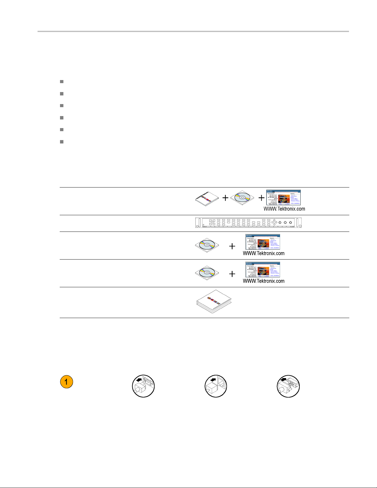
Where to Find More Information
Item Purpose Location
Quick Start User Manual
Installation and high-level
overview of instrument
operation
Preface
Online Help
Specifications and
Performance Verification
WFM, WVR, and AMM
Series Management
Information Base (MIB)
Service Manual Optional manual
In-depth instrument
operation and UI help
Specifications and
procedure for checking
instrument performance
SNMP command
reference for remotely
controlling the instrument
supporting module-level
servicing of the
instrument
Conventions Used in this Manual
The following icons are used throughout this manual:
Sequence Step Connect power
Network
XGA
Waveform Rasterizers Technical Reference v
Page 12

Preface
vi Waveform Rasterizers Technical Reference
Page 13
Incoming Inspection
The incoming inspection procedures are optional procedures that check the functionality of the instrument and require
no equipment other than a display. For a more robust inspection, see the performance verification procedures in the
Specifications and Performance Verification manual that is included on the User Documentation CD that was shipped
with your instrument.
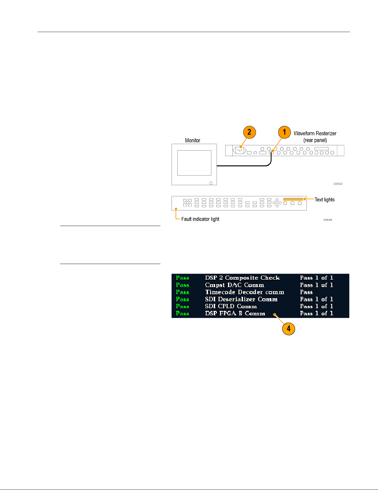
BasicTurnOnandSelfTest
1. Connect an XGA monitor to the
instrument.
2. Connect the AC power cord to the rear of
the instrument and to a 100 to 240 VAC
source. There is no power switch on
your instrument: it will turn on as soon
as you apply power.
3. Look at the front panel immediately after
you apply power. All of the buttons, the
text over the three knobs, and the Fault
indicator should light up.
Incoming Inspec
tion
NOTE. After a couple of seconds, the lights
in the buttons and text will turn off. After
about 15 seconds, the fault light should turn
off and the Power On diagnostic page should
appear on the monitor.
4. Verify that the instrument passes all self
tests. Any failures will be shown in Red.
The results of the Power On diagnostics
are erased from the screen, but you
can view them by selecting CONFIG >
Utilities > View Diagnostic Log.
5. After the diagnostics are finished, the
instrument state will be restored. When
the progress indicator in the lower-right
part of the screen is finished, the
instrument has finished initializing.
Waveform Rasterizers Technical Reference 1
Page 14
Incoming Inspec
Front Panel Test
tion
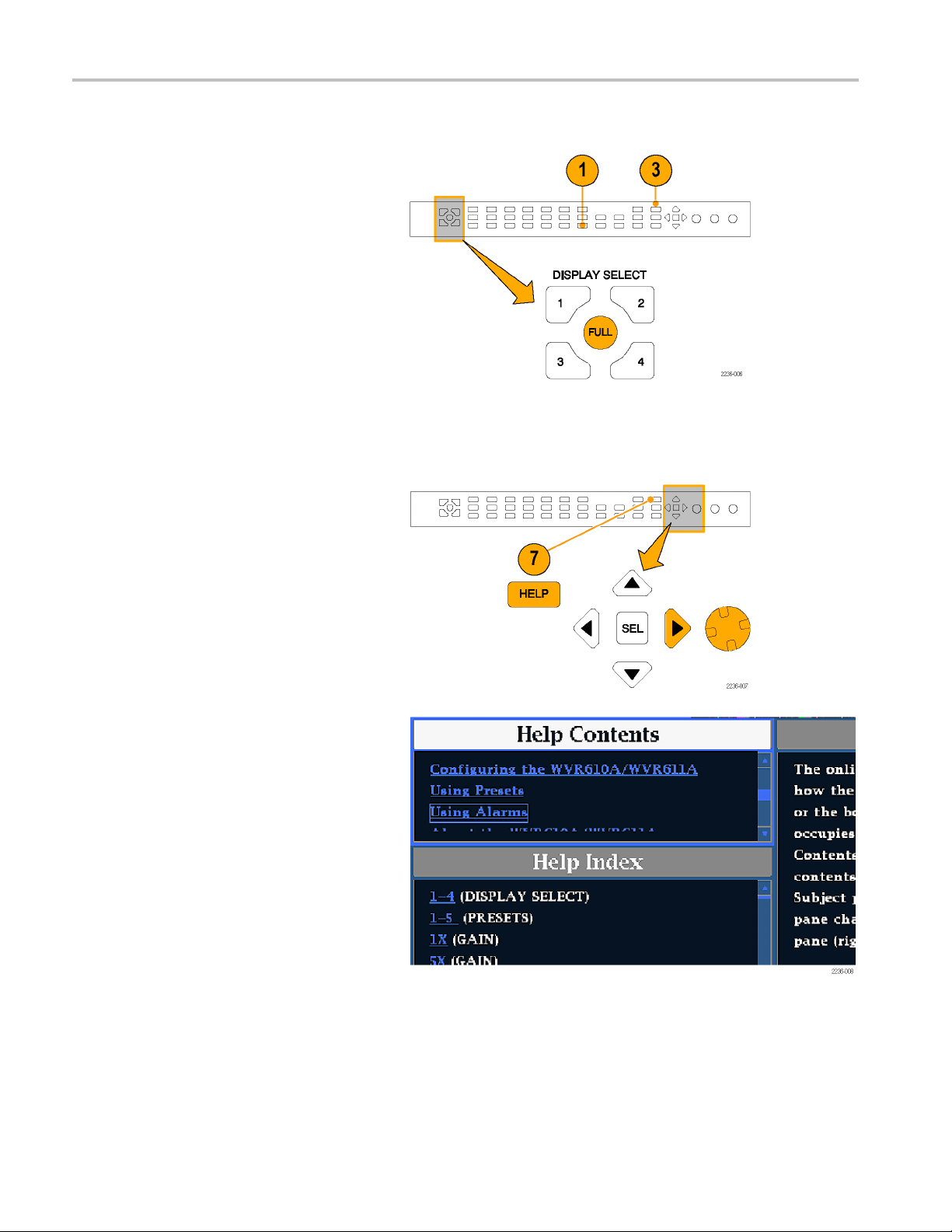
1. Press FACTORY
preset. Wait for the progress indicator to
show the process is complete.
2. Press FULL to make the active tile be
full screen.
3. Press HELP to
4. Press all the
Each button should flash as you press
it. Most buttons bring up related help
text. Some b
bring up the same information. The
HELP button, the four arrow keys, and
the SEL but
because they traverse the help panes
and content.
5. Press the right arrow key until the Help
Contents pane in the upper-left corner is
ted.
highligh
6. Turn the G
the selector box moves up and down the
list.
to restore the factory
display the help screen.
other buttons.
uttons, such as the presets,
ton do not bring up help text
ENERAL knob and verify that
7. Press HELP to exit help.
2 Waveform Rasterizers Technical Reference
Page 15
XGA and Extended Diagnostics Test
Incoming Inspec
tion
NOTE. Where th
if you prefer.
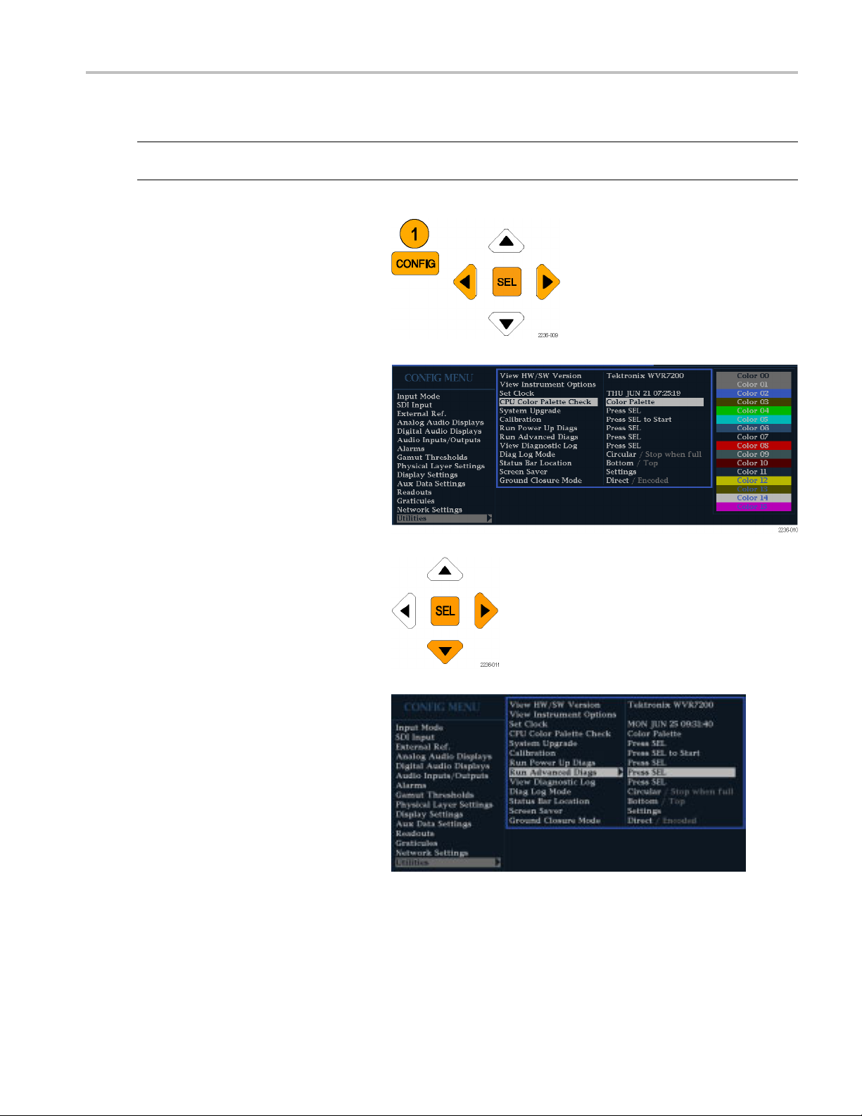
1. Press the CONFIG button to display the
configuration menu.
2. Select Utilities and then press SEL.
3. Select CPU Color Palette Check
and verify
displayed. This tests the XGA data path
from the CPU.
e following procedure says to press an arrow key, you can use the general knob on the front panel,
that 16 distinct colors are
4. Use the down arrow key to navigate to
Run Advanced Diagnostics and then
press SEL.
5. When the dialog box appears, use the
right arrow key to highlight the Continue
box and then press SEL to run the test.
6. Verify that the XGA DAC is working by
looking at the White and Red ramps at
the top of the screen, and at the Green
and Blue ramps at the bottom of the
screen. They should not have steps but
should show a smooth transition from
dark to light.
Waveform Rasterizers Technical Reference 3
Page 16

Incoming Inspec
7. Verify that the frequencies shown are
within 10 kHz, and that rates shown are
within 0.1 μs,
to the right.
tion
of the nominal values listed
8. Verify that the bus bit activity tests
(labeled Channel A:, Processor Video:,
and Composi
the bottom of the screen) are as follows:
All three tests show both a red and a
green bar in each bit location.
The Processors Video test shows
8bitsfrom
Hsync, a space, Vsync, a space, and
then the blank line. It is normal for
the Vsync b
9. Press SEL
the unit for normal operation.
te Video:, and appearing at
the CPU, a space, then
it to blink occasionally.
or cycle the power to reboot
QDR Clock = 25.174 MHz
VGA clock = 64.480 MHz
Audio PLL1 =
Audio PLL2 = 12.288 MHz
Hsync rate : Width = 0.9 μs
Vsync PW: Wi
12.288 MHz
dth = 62.5 μs
Fan Test
If the fault light in the lower left corner of the front panel is not on (Red), the fans are running. You should also be able to hear
them and feel air coming out the back of the instrument. At low temperatures, the fans will turn slowly and be very quiet.
4 Waveform Rasterizers Technical Reference
Page 17
Installation Variations
See the Quick Start User Manual that was shipped with your instrument for basic in stallation instructions. Read the following
information for other installation situations and for remote communication instructions, an optional procedure that is suitable
for incoming inspection of this product.
Connecting Directly to a PC
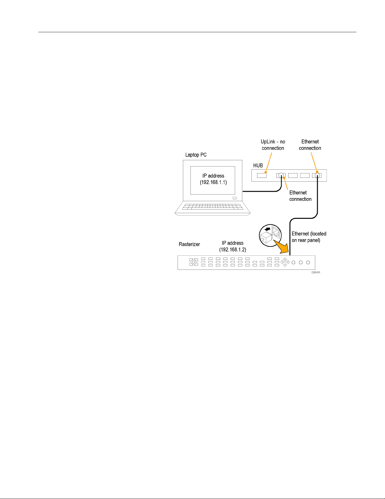
The following procedure will help you connect your instrument to a PC:
1. Connect the instrument to a PC through
an ethernet
crossover cable can be substituted for
the hub.
2. Set up the instrument as described in
the follow
Connecting to a Network.), choosing
Manual IP mode to set the IP address
manually
is compatible with the setting of your PC.
hub, as shown. A standard
ing procedures (See page 6,
. Be sure to set an address that
Installation Va
riations
3. If you are using an SNMP setup, use the
SNMP setup procedure.
Waveform Rasterizers Technical Reference 5
Page 18
Installation Va
riations
Connecting to a Network
The following topics cover configuring the IP settings, so that you can use your instrument over a network, and configuring
SNMP, which is required if you are using commands to control the instrument.
Connection and IP Settings
To al l ow ne t
automatically or manually. If your network does not use DHCP, you will have to m anually enter the address for the instrument.
To get an address, talk to your LAN administrator.
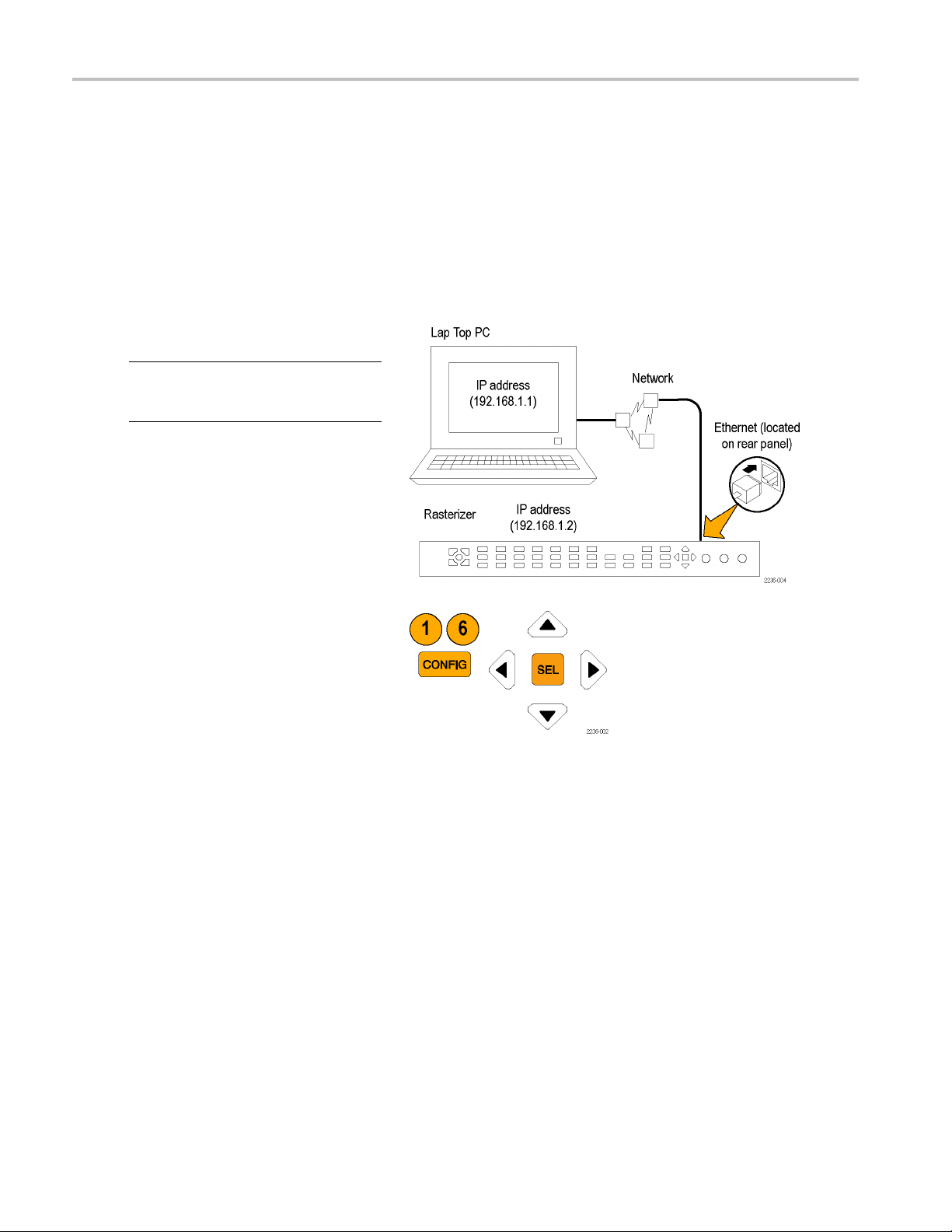
To connect your instrument to a network and
access it wi
NOTE. To connect directly between your PC
and the instrument, see Connecting Directly
to a PC.
1. Press CONFIG to display the
2. Select Network Settings > Web Enable.
work access to the instrument, you need to set the IP address. Network addresses can be assigned either
th a remote PC, do the following:
Configuration menu.
Press SEL to select On.
6 Waveform Rasterizers Technical Reference
Page 19

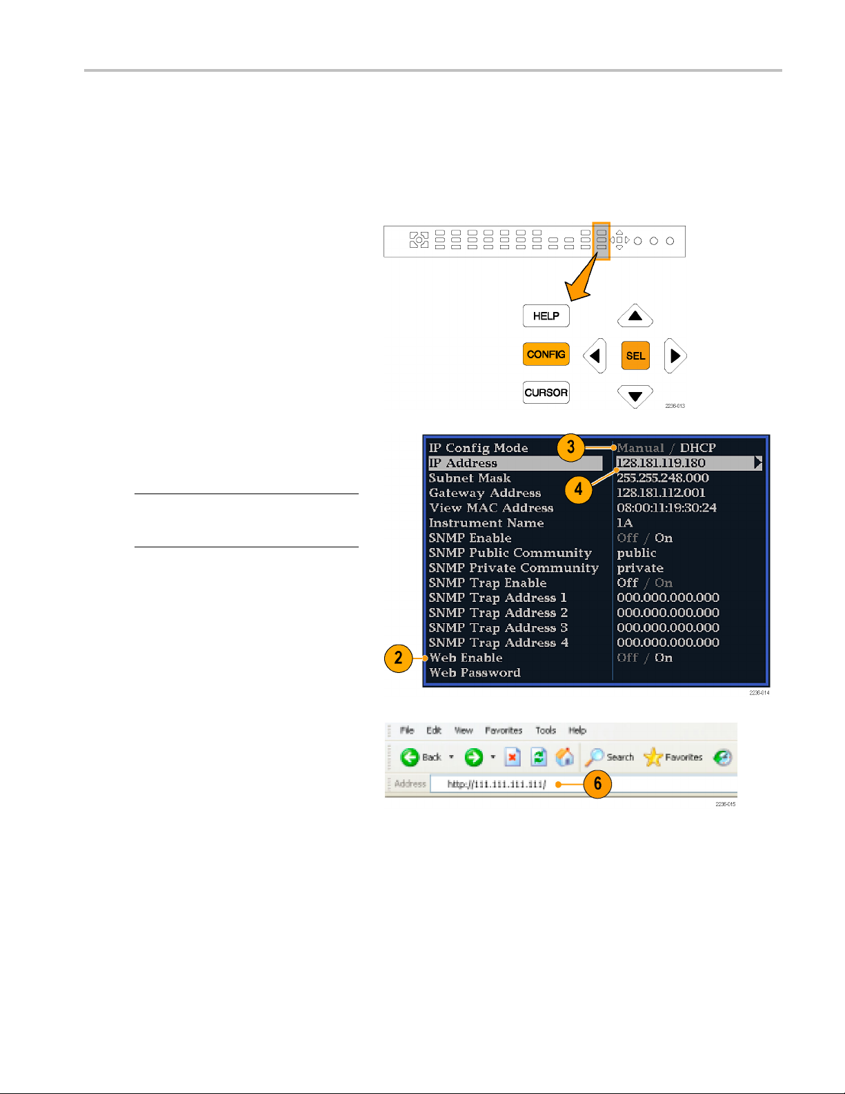
3. Set the IP Config Mode to Manual or
DHCP, depending on your network setup.
4. If you cannot use DHCP, set the subnet
mask and gatew
parameters in this menu; see your
LAN administrator for required values.
(Besuretous
between the PC and the instrument.)
You can also set the instrument name
and view the
ay address network
e compatible addresses
MAC Address.
Installation Va
riations
5. If the passw
be prompted for it when you connect to
the instrument.
NOTE. For h
the password, select Web Password, and
press the HELP button.
6. Press CONFIG to close the Configuration
menu.
ord is set, note it. You will
elp with entering or changing
Waveform Rasterizers Technical Reference 7
Page 20

Installation Va
SNMP Setup
If you intend to use SNMP commands to control the instrument (SNMP control is primarily intended for access through
automation systems), you need to set up SNMP parameters.
NOTE. The WFM, WVR, and AMM Series Waveform Monitors wfm_mon.mib and the WVR7120.mib c an be downloaded
from the instrument Web page.
The procedure to set SNMP settings is similar to that shown on page 2 for IP settings; the parameters that can be set follow:
SNMP Enable This entry in the Network Settings portion of the Configuration m enu allows you to
SNMP Trap Enable This menu entry allows you to turn on or off the traps that are sent out through SNMP.
SNMP Trap Address This menu entry allows you to set IP addresses to which SNMP traps are sent through
Private Community String This menu entry allows you to set the Private Community string. This string is
riations
turn on or off the remote access through SNMP.
SNMP. Traps can b e sent to up to four addresses when error conditions are detected.
NOTE. A value of all zeroes for the address will disable that trap output.
effectively a password. Without this string, SNMP commands cannot change values
in the instrument.
Public Community String This menu entry allows you to set the Public Community string. This string is
Remote Communication
ollowing topics cover remote communications that occur:
The f
an Ethernet network through a Web browser
Over
r an Ethernet network through a Java applet
Ove
r a cable using the optional remote front panel
Ove
NOTE. The Private String is necessary for SNMP access to write changes into
the instrument.
effectively a password. Without this string, SNMP commands cannot read values
from the instrument.
NOTE. The Public String is necessary for SNMP access to read values from the
instrument.
8 Waveform Rasterizers Technical Reference
Page 21
Installation Va
Using a Web Browser
You can use a Web browser to access the instrument and save screen captures, download presets, and download the error
log. Your instrument does need to be connected to an IP network via Ethernet. You will need to set the IP Config Mode, IP
Address, Subnet Mask, and possibly the Gateway Address, to meet your network configuration requirements.
To connect to the instrument using a Web browser, do the following:
1. Press CONFIG to display the
Configuration menu.
2. Select Network Settings > Web Enable.
Press SEL to select On.
3. Set the IP Config Mode to Manual or
DHCP, dep
ending in your network setup.
riations
4. Note the I
P Address for use in step 6.
NOTE. You m ay have to set other network
parameters in this menu; see your LAN
trator if required.
adminis
5. Press C
ONFIG to close the Configuration
menu.
6. Start your Web browser and type the
network address of the instrument (from
4) into the URL entry box like this:
step
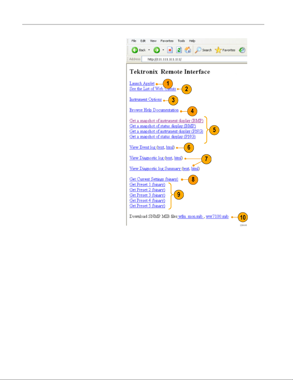
http://123.123.123.123/
1
Many Web browsers do not correctly interpret IP addresses with leading zeros. If the IP address shown in the Configuration menu
tains leading zeros as in 124.161.038.151, remove the "0" when entering it into the address line of the browser. For example,
con
124.161.038.151 should be entered as 124.161.38.151.
1
Waveform Rasterizers Technical Reference 9
Page 22
Installation Va
Click on the indicated items to:
1. Start the Java applet (see next
2. Display a list of Web clients (by network
3. Display a list of the options with which
4. Display instrument online help.
5. Capture the full or status bar displays
6. Download and display the Error Log as
7. Download and display the Diagnostic
riations
procedure).
address) curr
instrument.
this instrument is equipped.
in BMP or PNG
capture for saving to a file.
tab-delimited text or an HTML table.
Log or Sum
an HTML table.
ently logged into the
formats. Retrieves the
mary as tab-delimited text or
8. Download instrument settings to a file in
binary format.
9. Download Preset <N> to a file in binary
where <N> is any number from
format,
1to5.
10. Download each of the MIB files in ASCII
format.
Using the Java Applet
To further extend your control from a remote PC, launch the Java applet from the Web browser to change the instrument
ings, display and refresh the instrument screen, save screen captures, download and upload presets, and download
sett
the error log. The Java applet provides a m enu bar and a virtual front panel that gives you complete remote control over
instrument settings.
Note that the Web interface operation is optimized for screen resolutions of 1024 x 768 or higher. Operation on computers
lower resolution requires scroll-bar use to see the entire interface.
with
10 Waveform Rasterizers Technical Reference
Page 23

Installation Va
Java Applet Requirements
If you install Java on your PC, you can launch a Java applet to control the instrument. The Java Applet requires:
Version 1.4.1 (or later) of the Java Run-Time Environment (JRE) from Sun Microsystems installed on your PC. To
download the J
the Sun Microsystems URL:http://java.sun.com
Once you download the executable file, launch the installation software and follow the instructions.
Microsoft Internet Explorer 5.0 or later running on a Windows PC
Netscape on Apple Linux or on UNIX machines
NOTE. If you need remote operation on other platforms, use the Java Application, which is a stand-alone application that
provides al
1.4.1 or later, including Windows NT/2000/XP, Linux, Unix, and Mac OS X. The Java application, unlike the Java applet,
does not run within a Web browser and, thus, is not subject to the various browser limitations. You can download the
Java appli
of the Video Test Product pages.
The Java Application can be used to download instrument presets to a remote file and upload from the remote fi le to
the instrument.
l of the features of the Java applet. The Java Application can be run on any platform that supports Java version
cation package from the Tektronix Web site. Look for WVR Remote Software Package in the download section
RE (Java Run-Time Environment) plug-in from Sun Microsystems, download the appropriate code from
riations
Waveform Rasterizers Technical Reference 11
Page 24

Installation Va
Launching the Applet
When you launch the Java applet, it is downloaded from the instrument and launched. There is no software installation
required to use the applet (other than the Java Run-Time Environment noted previously). The instrument supports up to
three remote clients (screen updates become slower with each client added).
1. Launch the Web browser as described
2. Once the Remote Interface appears,
riations
under UsingaWebBrowser.
select Launch Applet and the Java
applet will be launched.
12 Waveform Rasterizers Technical Reference
Page 25

3. Use the menu bar of the Java applet
window to quickly access functions that
are not availa
Also, access the Configuration menu by
using these menus rather than a front
panel button
ble from the front panel.
.
Installation Va
riations
4. For front pan
front panel controls to remotely press
most instrument front panel controls.
5. Read the status bar the same way as you
would when i
the instrument display. (See Determining
Status At-A-Glance in the WVR6020,
WVR7020, a
User Manual.)
el functions, click the virtual
t is displayed directly from
nd WVR7120 Quick Start
Selecting Displays
1. To turn the display of the virtual front
panel on or off, click View > Control
Panel.
2. To t u r n t
Display Window on or off, click View >
Waveform Display.
he display of the Waveform
NOTE. T
independently of each other. Here they are
both displayed in the applet window.
Waveform Rasterizers Technical Reference 13
he displays can be turned on or off
Page 26

Installation Va
3. To change the refresh rates (defaults are
riations
every 10 seconds), do the following:
Select Options>Settings.
Adjust the refresh rates to the desired
periods in th
e Settings pop up.
Click OK to sa
NOTE. You can also display the instrument
online help from the Java Applet. Select
Help > Help.
browser window.
Operating
1. When adjusting variable settings, such
as vertical and horizontal position or
gain, the Remote Interface displays a
small window with a slider that you use
to adjust the value.
For example, to adjust the vertical
position of a waveform, select Scaling >
Vertical Position and adjust as desired.
2. To allow for display of pop-up menus
for each M EAS URE SELECT button,
the Remote Interface provides a menu
button; select the measurement for which
you want to display the pop-up menu.
3. Click the MENU button.
.. to open online help in a new
Notes
ve the new rates.
NOTE. You can also resize the virtual
control panel by clicking and dragging the
edges of the panel.
Usage Notes
The Remote Interface Control Panel differs from the instrument front panel in that it provides a menu. The menu provides
many controls, some of w hich duplicate functions that are directly available from the control panel. See the list that follows.
14 Waveform Rasterizers Technical Reference
Page 27

Menu Commands Description
File
Restore Setti
ngs
Restores inst
1 through Preset 5 or Factory) to the instrument
Save as Preset Saves the current instrument settings as setup in the instrument
(select any one of Preset 1 through Preset 5)
Load Presets From File This selection is disabled in the Java Applet. In the Java
Application (see NOTE on page 6), this selection restores the
presets (1 t
saved presets file that you select
Save Presets To File
This select
Application (see NOTE on page 6), this selection saves the
instrument presets 1 through 5 in a remote fi le
View
Exit
Active Tile
Closes the Java applet
Changes the active tile
Full Screen Changes display to Full screen mode
Freeze
l Panel
Contro
nCaptureDisplay
Scree
sh
Refre
Measure Various control items
Captures the current image for most of the possible displays
strument
in the in
s the display of the control panel window on and off
Toggle
es the Waveform Display window on and off
Toggl
es the Waveform Display
Updat
ents of this menu vary with the selection in the instrument
Cont
control panel (WFM, MEAS, AUDIO, GAMUT, VECT, PICT,
OTHER, or STATUS)
Scaling
Vertical Position Displays a window to enable you to adjust the vertical position
izontal Position
Hor
n
Gai
eep
Sw
plays a window to enable you to adjust the horizontal position
Dis
bles you to set the Gain to 1X, 5X, or set the variable gain
Ena
ables you to s et the sweep mode to One Line, Two Line, One
En
Field, or Two Field
g
nput
I
Ma
Inputs and Reference
Magnifies the Active Tile sweep rate
he settings displayed below Input correspond to the controls in
T
the Inputs and Ref groupings on the control panel
Options
Line Select & Cursors
commands
These menu entries below Options duplicate operation of the
Line Select and Cursors controls on the control panel
Refresh Rate Specifies how often the Waveform Display should be
automatically updated
Configuration
Window
Various controls not
available on the front
panel
Control Panel Moves the control panel window to the front if it is covered by
The menu entries below Configuration duplicate most of the
setups available by display the Configuration menu using the
CONFIG button on the instrument front panel
the Waveform Display
Waveform Display Moves the Waveform Display window to the front if it is covered
by the control panel
Installation Va
rument-stored setup that you select (one of Preset
hrough 5) to the instrument from any previously
ion is disabled in the Java Applet. In the Java
riations
Waveform Rasterizers Technical Reference 15
Page 28

Installation Va
Menu Commands Description
Using the WVR Remote Front Panel
The WVR Remote Front Panel (RFP) is available to permit remote control of the instrument. The WVR RFP works with
the main front panel and connects to the instrument through a cable. This cable may be up to 100 ft. long (a 25 ft. cable
ships with the WVR RFP).
Cable Description. The requirements for cables that can be used with this WVRRFP module follow:
riations
Help Displays the instrument online helpHelp
About
To co n figure the WVR RFP, follow the installation instructions that ship with the WVR RFP product.
To use the RFP module, use it as you would the integral fr ont panel of an instrument. All operating procedures in this
manual and the instrument online help apply to operation from the WVR RFP as well as the integral front panel.
Connectors (each end): 9-pin D-SUB, male, with jackscrews
Cable: nine conductors, 26 gauge or heavier, shielded
Construction: Pins 1-9 of each connector wired to corresponding pins of the alternate connector (connect pin 1 to pin 1,
and so on
). Shield or drain wire bonded to metal shell at each end.
Displays version information about the Java applet
Maximum
length: 100 ft
16 Waveform Rasterizers Technical Reference
Page 29

Display Informa
tion
Display Infor
This section describes instrument displays and their respective pop-up menus.
NOTE. All pop-up menus are displayed by pressing the specified button for three seconds. To hide a pop-up menu,
press the specified button again.
mation
Waveform Display
The WFM button displays the Waveform (WFM) display, which is the voltage versus time display used to view a waveform.
You ca n vie
or YPbPr), and you can apply filters to the signal. You can also display an SDI input as though it were a composite signal.
You can also control (in the CONFIG menu) whether EAV, SAV, and ANC data is included in the display.
Waveform Display Elements:
1. Is blank when vertical gain is X1;
2. Lists the currently displayed waveform
w the input signal in line or field sweep. You can choose which SDI signal elements are displayed (RGB, YRGB,
otherwise indicates that V Gain is x5 or
variable.
color-space. Dashes (--) indicate
components not displayed.
3. Lists the currently selected field and line
(when in Line Select mode).
4. Lists the current sweep rate for tile.
5. Lists the Mag rate if MAG is on.
Waveform Pop-up menu and settings
The Waveform pop-up menu enables you to choose the display style and display mode used in the active tile (SDI inputs
only), select a filter to apply to the input signal, or center the w aveform in the display.
To choose a display mode, select from the following the choices (only available while displaying SDI inputs) in the menu:
YPbPr - Displays the input as Luma (Y) and color difference (Pb, Pr) c omponents.
YRGB - Displays the input as Luma (Y), Red (R), Green (G), and Blue (B) components.
RGB - Displays the input as Red (R), Green (G), and Blue (B) components.
SDI > Composite - Displays the SDI input as if it has been encoded into composite. The sync and burst in this mode are
synthetic and convey no information about signal quality.
When viewing 525-line SDI input as a composite waveform while using line select mode, both burst phases may appear
when you would e xpect to see only one. This is because the line selection in SDI Mode is an odd/even selection, and
composite signals are normally viewed with a one-of-four or one-of-eight line selection.
Waveform Rasterizers Technical Reference 17
Page 30

Display Informa
To choose how the signal components are displayed in the active tile, use the Display Style menu setting (SDI inputs
only) to select
tion
:
Parade style -
Overlay style
The Waveform p
specific characteristic of the input. For example, to measure amplitude, you may want to use a Luma or Low pass filter
to remove the high frequency components.
To choose a filter select one of the following filters from the Waveform menu:
Flat - Display with the full available bandwidth.
Luma or Low Pass- Display only the low-frequency portion of the signal.
Chroma - Display only the portion of the s ignal with frequencies near the color sub-carrier. For Composite inputs only.
Flat + Lum a - A combination of a Flat and a Luma waveform from a Composite input; it shows two waveforms
in parade c
NOTE. For SDI displays, such as RGB mode, the available filters are Flat and Low P ass. For Composite displays, the
available filters are Flat, Luma, Chroma, and Flat+Luma.
To cancel any horizontal or vertical position adjustments and restore the trace to the default position, select Center
Wavefor
m and press SEL. For a tile in WFM mode, this puts the baseline at the zero graticule.
has all the components shown one beside the other.
- has all the components drawn at the same location so that they appear one on top of the other.
op-up menu Filter selection allows you to select filters to be applied to the video. This is useful for isolating a
onfiguration.
18 Waveform Rasterizers Technical Reference
Page 31

Vector Display
The VECT button calls up the Vector and Lightning displays, which provide for selection between two plots of the color
portions of the signal.
Lightning Display Elements:
1. Line. Pressing the LINE button sets the
horizontal g
ain to 1X.
Display Informa
tion
2. Field. Press
the horizontal gain to 5X.
3. Mag. Pressing the MAG button enables
you to adjust the horizontal gain using
the GENERA
ing the FIELD button sets
L knob.
Lightning & Vector Display
Elements
4. Display Type. The selected display,
5. Bar Target Setting. The bar target
6. Phase. Appears in Composite Vector
:
either Lightning or Vector.
setting, either 75% or 100%.
inputs only.
Vector Pop-up Menu
ctor pop-up menu enables you to specify the display type and display mode (SDI inputs only), to set the bar targets,
The Ve
and to center the waveform in the display.
To choose the display type (SDI inputs only), use the pop-up menu to choose either:
Vector - The Vector display shows a plot of the R-Y signal on the vertical axis and the B-Y signal on the horizontal axis.
This display is useful for looking at hue and saturation of the colors, but does not show luminance information.
Lightning - The Lightning display shows the same color signals as in vector, but they are plotted versus luminance. One
color difference signal is plotted in the top half and the other in the bottom. Lightning is useful for checking chroma and
luma gain, and for checking chroma to luma delay using the timing marks that show errors in the green to magenta
transition on a color bar signal. This is a Tektronix proprietary display and is for SDI signals only.
To select which scaling should be used in the active tile for either the Vector or Lighting display, use the menu to select
75% or 100% scaling.
To cancel any horizontal or vertical position adjustments and restore the trace to the default position, use the up/down
arrow keys to select Center Waveform in the menu. Then:
For a Lightning display, press SEL to center the waveform. The trace is set back to the center of the tile.
For a Vector display, press the right-arrow key to select the color you want to locate at the center of the display.
For additional vector graticule options, see the Configuration > Graticules menu and select I/Q axis or Compass Rose.
Waveform Rasterizers Technical Reference 19
Page 32

Display Informa
tion
Timing Display
Pressing the MEAS button displays a Tektronix proprietary display that simplifies measuring the timing difference between
two signals as the timing is corrected. Using the Tektronix Timing display enables you to easily compare and correct the
timing between two signals.
Display Elements:
1. Input Signal
circle representing timing of input signal
relative to the reference.
2. Reference Indicator: A cross-hair
indictor ce
represents the reference signal.
3. Vertical Offset: The timing difference
between the reference and input signal.
4. Horizontal Offset: The timing difference
between the reference and input signal.
Indicator: A single
ntered in the display
1
5. Relative to: Indicates the chosen zero
point for
1
More complex timing relationships display multiple circles. See Timing Displays for Simple Versus Complex Timing.
2
Rear Panel is the default setting, where offset is shown as zero when the input and reference are at the same timing at the rear panel of the
instrument. If you select Saved Offset, you can save the timing from one signal, and then display the timing relative to that saved offset.
thetimingdisplay.
2
Measure Pop-up Menu
The Measure pop-up menu enables you to s ave a timing setting for comparison with another signal and specify the zero
f the timing display.
point o
e the timing of the current input as an offset to the timing display, use the Save Offset menu entry. The current timing
To sav
becomes the zero point for the saved offset mode of the timing display. This applies to both the cross-hair target in the
middle of the display and the numeric readouts.
. You cannot save the timing offset if either the input or reference is missing or unlocked. You also cannot save a
NOTE
reference when in internal mode. Saving an offset in these conditions would lead to misleading results so it is not allowed by
the instrument. A warning message will appear on the screen if you attempt to save the offset when it is not allowed.
20 Waveform Rasterizers Technical Reference
Page 33

Display Informa
Save Offset allows you to measure the timing between inputs or to m atch multiple signals. To select the definition for the
zero timing off
set, use the Relative To: menu entry to select one of the following:
tion
Rear Panel,wh
of the instrument.
Saved Offset, which means that the timing will be shown as zero offset when the input signal matches the timing of the
signal that was present when the offset was saved using the Save Offset menu entry.
This selection changes both the numeric readouts and the target in the middle of the timing display.
Timing Disp
The number of circles, with each representing
a time offset, varies with the complexity
of the timi
input signals. If you are timing input signals
with rates that are integer multiples of the
reference
the timing deterministically and displays the
relationship as one circle (offset) relative to
the cross
Such cases include timing an NTSC input
(multiplier of 1) or a 525 SDI input whose
frame ti
against an NTSC reference, which has a
frame time of 66.73 ms.
ng between the reference and
rates, the instrument can measure
-hair (reference as is shown).
me is 33.36 ms (multiplier of 2),
ich means the timing offset will be shown as zero when the two signals are timed down at the rear
lays for Simple Versus Complex Timing
If you time input rates that are not
integer multiples of the reference rates,
the instrument cannot measure the
timing deterministically, so it displays the
relationships as several circles. Each
circle represents a possible timing offset
measurement relative to the reference
cross-hair. Display emphasis is given to the
circle that times closest to zero offset and the
numerical readouts track this pair.
Nondeterministic cases include timing of
slow rate inputs against fast frame-rate
references or when timing video against film
rates.
Waveform Rasterizers Technical Reference 21
Page 34

Display Informa
tion
For a case where
would display, consider an input of
1080p/23.98 Hz with a reference of
NTSC/59.94 Hz
The different
relationships between the signals that
repeat once for every four fields of the
input and five
(shown right).
Because this allows for five possible
ways to measure timing between these
two signals
four circles, with emphasis and readouts
as previously described above.
Picture Di
Pressing the PICT button calls up the Picture display, which lets you see the picture generated by the video signal. You can
choose to display the picture with or without a Picture Frame, VChip, Closed Captioning (CC), and Safe Area Graticules.
Display Cha racteristics:
multiple relationships
:
rates result in timing
frames of the reference
, the timing display shows
splay
In full-screen mode (shown), there is no
cropping.
Pictures are decimated horizontally or
ally to achieve the correct aspect
vertic
ratio. This decimation may cause some
artifacts. This behavior m ay be evident
onaswe
Also s
Aspect Ratio for related information.
Display can be set to include Closed
Captioning text or Teletext overlaid on
the pi
ep signal.
ee the online help for the Picture
cture.
22 Waveform Rasterizers Technical Reference
Page 35

VChip, CC-Display, Teletext,
and Safe Area Gr
aticule
Characteristics:
1. VChip Area: Displays detected VChip
ratings from any of these systems: MPAA
(US), TV (US), Canadian English, and
Canadian French. VChip information is
labeled CA (Content Advisory).
2. Safe Graticules: SMPTE, BBC, and
ARIB B-4 standards for safe area
graticules allow for selection of up to two
Safe Area and two Safe Title graticules.
Custom graticles with adjustable areas
canalsobespecified.
3. Closed Caption Text and Teletext
Area: Displays closed captioning or
Telet e xt, c o n figurable to decode to the
following Closed Caption and Teletext
standards:
Display Informa
tion
For Composite: EIA-608-line-21
(VBI), TeletextB VBI (PAL)
For SD: EIA-608-line-21, EIA-608
(ANC), EIA-608 (708), EIA-708, and
TeletextB VBI (625)
For HD: EIA-608 (ANC), EIA-608
(708), TeletextB VBI, TeletextB OP47
SDP (ANC), and TeletextB OP47
Multi (ANC)
Waveform Rasterizers Technical Reference 23
Page 36

Display Informa
NOTE. See Monitoring Closed Captioning (CC), Teletext, and Safe Area Compliance in the Quick Start User Manual.
PICT Pop-up Menu
The Picture pop-up menu enables you to optionally display ele ments of the video signal outside the active video, turn on
display of Close-Caption (CC) text overlaid on the picture, and turn on up to four save area graticules, and otherwise
control the PICT display.
To see only the active video portion of the signal, use the menu to switch Picture Frame to On; to see elements of the signal
outside the active video, switch Picture Frame to OFF to view user data, embedded audio, and elements in the vertical
interval.
NOTE. You can see signal elements outside the active video only when the PICT display is set to FULL. You will not be
able to see sync signal elements on Composite signals.
To view CC text overlaid on the display, use the menu to switch Display Closed Captions to ON.
To select the CC service used to display closed captions, use the menu to set EIA-608 CC Service to a CC or text channel.
tion
NOTE. If you set a PICT display for additional tiles, each one affords independent control of the CC setup. You can turn it
on for one tile and leave it o ff for another, or you can set it to display differently from one tile to another. Conversely, CC
configuration set in the CONFIG menu applies globally to all tiles set to PICT.
NOTE. To set the global configuration for CC decoding, use the Aux Data Settings submenu of the CONFIG menu. You can
set the CC transport type and other global parameters. See Monitoring Closed Captioning and Teletext in the Quick Start
User Manual for more information.
When monitoring to ensure that branding or other elements do not overlay essential text or video action, use the PICT menu
to select a Safe Action and Safe Title graticule. The Safe Action Area is the maximum image area within which all significant
action should be contained, and the Safe Title Area is the maximum image area within which all significant titles should be
contained. You can select standard or custom safe area graticules.
To display safe area graticules overlaid on the display, use the menu to switch up to four Safe Area graticules settings to ON.
NOTE. Select and/or define these graticules g lobally in the Graticules submenu of the CONFIG menu. You can set the
Safe Graticule Standard and define dimensions and offsets for custom Safe Graticules. See Monitoring for Safe Area
Compliance in the Quick Start User Manual for m ore information.
24 Waveform Rasterizers Technical Reference
Page 37

Audio Display
Pressing the AUDIO button brings up the Audio D isplay. The Audio display provides level meters and a phase display for
monitoring audio signals. The Audio display always shows the level meters and correlation meters. When you choose to
display the phase plot (also known as Lissajous), the left portion of the Audio tile displays the level meters and the right
portion the Phase display. You can display Surround Sound in the right part of the A udio Tile, instead of the phase plot.
See the figure that follows.
Display Elements
Display Informa
tion
Element Descriptions
Element Description
l meters
Leve
Phase or Surround display Selects between the Phase display, where the phase of a selected pair o f
Audio source/setup Displays selected audio input and related setup information, such as
Waveform Rasterizers Technical Reference 25
Can include Dolby channels 9 and 10 if Dolby options are present.
channels is plotted against an X-Y or sound-stage plot, and the Surround
play, where all the channels levels display in positions matching their
Dis
place in a surround-sound listening environment.
Listening Mode when in Surround display.
Page 38

Display Informa
Element Description
Level meter labels
Level meter ballistics readouts Displays the selected dynamic response characteristic.
Axes
Phase correlation meters Displays the phase correlation between the two-channel bars under which
Test level
Level meter scale and units
Dolby Guardband thermometer Guardband limits can be set for SD, HD, 3G, DL, and CMPST signals. A
tion
and Peak program level indicators
Identifies the signal in each meter bar. The labels vary a ccording to
whether the au
pairs, surround channels, or Dolby sources (the Dolby source labels
include Dolby type).
Shows the orientation of the two audio signals when displaying phase;
shows the orientation and amplitudes of the sound field when displaying
surround so
it appears.
appears in the Phase display.
Indicate,
configurable limits set up for the display. Above the Test level, the bar
displays in a yellow color. Above the Peak level, the bar displays in a red
color. Te
By defaul
and dB relative to 0.775 Volts (dBu) for analog inputs. The 0 dB mark is
digital Full scale for digital inputs and 0 dBu for analog inputs. You may
also set
See also CONFIG > Digital Audio Display > set meter type to, and CONFIG
> Analog Audio Display > set meter type to.
Dolby G
you can monitor whether or not guardband limits are being exceeded.
dio sources to the level meter bars are normal channel
und. (Axes are selectable for an X-Y or Soundstage plot.)
The meter of the pair selected for the Phase display also
as diamond-shaped markers between the level bars, the
st level is also known as Reference level or Line-up level.
t, the units are in dB relative to full scale (dBFS) for digital inputs
the 0 dB mark to either the Peak Program level or the Test level.
uardband thermometer is displayed on the Audio display so that
The surround display is described under Monitoring Surround Sound in the W VR6020, WVR7020, and WVR7120
NOTE.
Quick Start User Manual.
NOTE. The loudness measurement supports three types of filter: Flat, A-weighted, and RLB (ITU-R BS.1770). The
measurement can be viewed in the Audio Session display.
Above-bar Warning Messages
This instrument displays warning messages above the level meter bars. The warning messages that can appear above
the bars as follows:
Clip. The number of consecutive samples equals or exceeds the # Samples for Clip setting.
OVER. The signal has been at or above the specified Over Level for a time exceeding the Duration for Over setting.
In-bar Warning Messages
This instrument displays warning messages within the level meter bars. The warning messages that can appear are
hown below in order of priority.
s
26 Waveform Rasterizers Technical Reference
Page 39

Display Informa
UNLOCKED. The instrument is not locked to an incoming signal on the i ndicated input channel. Data cannot be decoded
and all data and
the input, or if embedded audio is selected, the VIDEO input is unrecognizable.
AES PARITY. The incoming subframe does not have even parity as specified by the digital audio standards. The data sample
is unreliable and is ignored. The level meters and Lissajous display treat the sample as a zero sample.
AES CRC ERROR. The CRC code in the AE S channel status packet is incorrect. Sometimes the C RC code is set to zero,
indicating t
other errors are ignored. This means that if an AES input is selected, nothing recognizable is present on
hat the signal is missing; when this is the case, this message is not displayed.
tion
MUTE. The num
SILENCE. Th
DISABLED. I
listening mode is selected with a reduced number of channels.
AES V BIT. Indicates that the Validity bit is set high for one or more data samples. In the AES/E BU standard, a set validity
bit indicates that the sample is not suitable for conversion to audio. By default, the level meter bars and Lissajous display
treat the a
NO AUDIO. I
NOT PRESE
input has a coding mode indicating a reduced number of channels.
DOLBY D. Indicates an AES or embedded input is Dolby Digital.
DOLBY E. Indicates an AES or embedded input is DOLBY E.
ber of consecutive all-zero samples equals or exceeds the # Samples for Mute setting.
e signal has been at or below the specified Silence Level for a time exceeding the Duration for Silence setting.
ndicates that an audio bar is not active. This message is mainly seen with a Dolby Digital source when a
ffected samples as zero samples.
ndicates that an AES or embedded input has the Non audio bit set.
NT. Indicates that an audio bar is not present in the current audio input. This can be present if a D olby Digital
Audio Pop-up Menu
The Audio pop-up menu enables you to select the audio input source and specify whether a phase display or a
surround-sound displays appears in a subtile to the right of the level meter display.
To select the source for the Audio display, select Audio Input in the m enu and set a source. The number of available
sources depends on which audio option is installed. Choosing any given input will make that audio the monitored signal
regardless of which video input is active. Alternatively, you can choose Follows video to enable the mapping that allows
changing the audio source as the video input selection is changed.
NOTE. Use the CONFIG menu to select the mapping of input to bar, the meter type, and the Follows video mapping of
audio to video.
Analog Out Atten is used to asjust the levels to the rear panel analog outputs.
To add a 2-channel phase display to the audio tile, set Aux Display to P hase Display in the Audio pop-up menu. A phase
display is also called a "Lissajous" display.
To choose the plot style of the Phase Display, select between the following two entries in the pop-up menu:
Sound Stage has axes rotated at a 45 degrees.
X-Y has axes that are horizontal and vertical.
To choose the pair of inputs that is displayed in the phase display, select Phase Pair and set a value. You can also select
Custom, and then specify individual channels for the input pair, using the Phase Channel A and Phase Channel B entries.
Waveform Rasterizers Technical Reference 27
Page 40

Display Informa
To add a multi-channel surround sound display to the audio tile, set Aux Display to Surround Sound in the Audio pop-up
menu. You can al
tion
so enable either or both of the following entries:
Dominance Ind
cross-hairs pointer (surround display only).
Loudness. When set to Flat, results i n a non-weighted response; when set to A-weighted, results in a response that
more closely matches that of the human ear.
NOTE. The Aud
Cologne, Germany. Surround Sound: Radio-Technische Werkstaetten GmbH & Co.
icator. When on, indicates the location of the dominant sound in the surround sound image using a
io Surround Sound display is courtesy of Radio-Technische Werkstaetten GmbH & Co. KG (RTW) of
LTC Waveform Display
Pressing the OTHER button brings up a display of an LTC waveform when one is present. This enables you to check the
LTC amplitude and noise, and verify that LTC is locked to the video. The display has two vertical scales, one in Volts
and the other in dBu.
Display Elements:
1. Vertical
scaleinvolts.
2. Time Code: when displayed, indicates
that the LTC time code is locked to the
video.
3. Horizo
scale.
Scale (V): The vertical display
ntal Scale: The horizontal display
4. Vertical Scale (dBu): The vertical
display scale in dBu.
OTHER (LTC) Pop-up Menu
ther pop-up menu provides access to the Center Waveform function. The Center Waveform function is used to
The O
cancel any horizontal or vertical position adjustments and restore the trace to the default position. After bringing up the
pop-up menu, press SEL to center the waveform.
28 Waveform Rasterizers Technical Reference
Page 41

Gamut Display
Pressing the GAMUT button calls up the Gamut Display. The Gamut display provides three proprietary Tektronix display
types to enable you to easily and quickly check the gamut of an SDI signal. You can choose from the Arrowhead, Diamond,
and Split Diamond displays. The Arrowhead display provides NTSC and PAL composite gamut information directly from the
SDI signal. The Diamond and Split Diamond displays provide a reliable method of detecting invalid colors.
Display Elements:
1. High threshold: Shows the currently
specified high threshold (Diamond High
or Arrowhead Max).
2. Low threshold: Shows the currently
specified low threshold (Diamond Low).
3. Gamut display type: Shows the
selected Gamut display type - Diamond,
Split Diamond, or Arrowhead.
4. Threshold indicators: Indicates the
threshold settings using blue dashed
lines.
Display Informa
tion
GAMUT Pop-up Menu
The GAMU
in the GAMUT display, use the pop-up menu to select from the following displays:
T pop-up menu allows you to select the type of gamut display shown in the active tile. To c hange the display type
Diamond shows Gamut violations of the SDI input if translated to RG B color space.
Split Diamond offsets the two halves of the Diamond to allow you to better see negative RGB Gamut errors.
Arrowhead shows Gamut violations of the SDI input if translated to the Composite domain.
Waveform Rasterizers Technical Reference 29
Page 42

Display Informa
tion
Status Display
Pressing the STATUS button calls up the Status display, which provides several views of signal status. Status displays are
text displays that show signal status. You can view current alarms and errors (those occurring now and within the last few
seconds), a history of errors and alarms (up to 10,000 entries), video error statistics or audio error statistics. You can display
a different Status display type in all four tiles.
NOTE. Press the HELP button and then press the STATUS button to explore help topics on the following status types.
Status display types available:
1. Video Session: Control the Video
Session settings.
2. Audio Session: Control the Audio
Session settings.
3. Aux(iliary) Data Status:View
closed-caption, Teletext, video index,
AFD, WSS, and V-chip related status.
Select to view metadata over VAnc.
4. Dolby Status: View Dolby metadata for
the currently monitored audio source
(AES and embedded input).
For instruments equipped with Option
DDE, Dolby Timing and Dolby VANC
data is available. For the latter, you can
select to view metadata from the audio
data stream or from the VANC.
5. Error Log: Control the error logging
settings.
6. Alarm Status: View current alarm status.
7. ARIB Status: Check for the presence
and status of ARIB-based information
encoding. The rasterizer supports
TR-B.22, TR-B.23-1, TR-B.23-2, B.35,
B.37, and B.39 ARIB standards. To view
the ARIB content displays, enable this
option in CONFIG > Aux Data Setting s
> ARIB Content Display.
30 Waveform Rasterizers Technical Reference
Page 43

8. SDI Status: View two measurements
of signal jitter cable loss in both dB and
meters of the s
calculated source level. With option
PHY, automatic measurements of eye
amplitude, r
and rise-fall difference are also displayed.
9. Audio Control: View the information
on audio frame number, sampling
frequency, active channels, and relative
audio-to-video delay of each channel,
as encoded in the audio control packet
metadata.
10. Audio Channel Status: View the
specifie
elected cable type, and
ise time, fall time, overshoot,
d channel in the specified format.
Display Informa
tion
STATUS Pop-up Menu
The STATUS pop-up menu enables you to mute alarms, select the type of display that appears in the status screen, and set
options related to the selected display type.
Waveform Rasterizers Technical Reference 31
Page 44

Display Informa
STATUS Colors
The STATUS display messages and values appear in different colors to help indicate signal status:
tion
Color
White
Green
Yellow
Red
Gray Indicates alarm status state of an un-enabled alarm
Description
Identifies informational items and represents changes in the instrument
state
Indicates error conditions that have cleared
Indicates that there is a warning condition (that might require attention) or
that an error has occurred within 2 seconds
Indicates signal information that has been found to be in an ongoing error
state
Alarm Status Errors
When RGB and/or Composite Gamut errors are detected, the associated lines in the A larm Status display have c haracters
that indicate which gamut threshold(s) are exceeded for each component. The following error codes that may be displayed:
NOTE. To monitor alarms remotely, use a PC to monitor SNMP traps over the E thernet port (the PC must have SNMP
trap service installed). Before SNMP traps can be sent, you must enable and configure the instrument for SNMP control
using the Network Settings submenu of the CONFIG menu.
Indicator Description
R
r
G Signal exceeds the high gamut limit for the green component (RGB gamut)
g
B
b
C Signal exceeds the high gamut limit for the chroma component (composite gamut from
c
Y
y
Signal exceeds the high gamut limit for the red component (RGB gamut)
Signal exceeds the low gamut limit for the red component (RGB gamut)
Signal exceeds the low gamut limit for the green component (RGB gamut)
Signal exceeds the high gamut limit for the blue component (RGB gamut)
Signal exceeds the low gamut limit for the blue component (RGB gamut)
SDI input)
Signal exceeds the low gamut limit for the chroma component (composite gamut from
SDI input)
Signal exceeds the high gamut limit for the luma component (composite gamut from
SDI input)
Signal exceeds the low gamut limit for the luma component (composite gamut from
SDI input)
Diagnostics Log
This log contains the results of diagnostics tests, boot-ups, and advanced diagnostics that were performed. View the
log directly on the instrument by pressing CONFIG >Utilities > View Diagn ostic Log, or by clicking on the Diagnostics
Log link on the Remote Web page.
32 Waveform Rasterizers Technical Reference
Page 45

Display Informa
Error Log
The instrument maintains an error log (also called the ev ent log) in which every logged entry is time-stamped. When you
enable Timecode, events are time-stamped with the timecode embedded in the video (or LTC) signal. Enable Timecode from
the Aux Data Settings submenu of the Config menu. View the log directly on the instrument by pressing S tatus > Error Log ,
or by clicking on the Error Log link on the Remote Web page.
CAUTION. The time of day time stamps in the error log are based on the system time of the instrument when the logging
process starts. Changing the system time of the instrument while the error log is in the Running mode does not change the
time stamps in the running error log. You must stop and restart the error log before the error log will use the new system time.
Error log size. The error log can contain up to 10,000 entries. Recording each individual event separately would quickly
fill the log. To handle this problem, the instrument classifies log entries as one of the following:
Single shot. One isolated occurrence is logged as one entry.
Continuous. Uninterrupted sequence of occurrences is logged as two entries marking the beginning and end of the
sequence.
By default, alarms are not enabled for logging. Use the Alarm Setup submenu of the Configure menu to select the number of
monitored error conditions.
tion
Eye Display
ruments equipped with Option EYE, pressing the EYE button calls up the Eye display (for SDI inputs only). The Eye
For inst
display presents an eye pattern diagram of the SDI input, which lets you verify electri cal characteristics of the SDI transport
layer. You can measure analog characteristics of the SDI input on the eye pattern using the graticule or voltage and time
s. Two jitter indicators provide two independent measurements of jitter. You can also set alarms on various parameters
cursor
(see your instrument online Help). For more information on jitter, search the Tektronix Web site for jitter application notes.
Waveform Rasterizers Technical Reference 33
Page 46

Display Informa
tion
Display Elemen
1. Eye Pattern: Di
can use for SDI transport verification and
analysis.
2. Jitter Thermometer: Displays jitter
value and rela
3. Equalized Ey
the CONFIG menu, the Eye pattern is
equalized, reducing the jitter noise floor.
Amplitude Cu
indicate the actual signal amplitude.
4. Cursor Readouts: Provide for direct
measurements of amplitude and time on
the Eye.
5. Eye Patter
Eye (SD)/20 Eye (HD). The latter types
can help reveal when jitter at the parallel
word rate i
6. Jitter HP
Jitter High Pass Filter, set in the CONFIG
menu.
ts:
splays a waveform you
tes it to alarm limits.
e Indicator: If enabled in
rsor measurements do not
n Type: Either 3 Eye, or 10
s present.
F: Indicates the setting for the
At the end of a long cable, the eye diagram may appear so noisy that there is little or no discernable opening. In this
on, limited use of the eye diagram is still possible by selecting Equalized Eye mode. The equalizer compensates for the
situati
effects of cable length by applying an inverse response function and then reslicing the signal to a logic level. This causes
amplitude information to be lost, but preserves the effects of jitter in the signal.
If the equalized eye display appears clear with a substantial eye opening, then the signal is likely to be recovered error-free.
r, if it appears noisy with little eye opening, then there is more potential for data errors to occur in the receiver.
Howeve
NOTE. For information on taking Eye measurements, see the Monitoring the SDI Physical Layer section of the WVR6020,
WVR7020, and WVR7120 Quick Start User Manual.
Eye Po
Pressing the MEAS button on the front panel will bring up the Eye pop-up menu. This menu enables you to center the eye
waveform and, more importantly, specify the operation of the Jitter detector that drives the Eye display.
NOTE. Eye diagrams that you display in the upper two display tiles are driven by the Jitter1 detector; those in the lower
two tiles, by the Jitter2 detector. To display two Eye diagrams with independent Jitter detectors, display one in an upper
tile and one in a lower tile.
p-up Menu
34 Waveform Rasterizers Technical Reference
Page 47

Jitter Display
The Jitter Display can be used once you have configured the instrument for Eye measurements and is only available with
option PHY. This display shows you the wave shape of the jitter and allows you to view additional time-domain information,
such as whether there are jitter components that are synchronous or nearly synchronous to the video line or frame. You
can also set alarms on various parameters (see your instrument online Help). For more information on jitter, search the
Tektronix Web site for jitter application notes.
Display Elements:
1. Jitter Waveshape: Displays the jitter
wave shape (
shows no jitter). This s hape is modified
by the high-pass filter (HPF) setting.
2. Jitter Thermometer: Displays jitter
value and r
the image to the right
elates it to alarm limits.
Display Informa
tion
3. Jitter HPF
Jitter High Pass Filter, set in the CONFIG
menu.
: Indicates the setting for the
High-Pass Filter. The high-pass filter bandwidth setting allows you to show only jitter terms above the selected filter
frequency. W hen you select a filter setting, depending on the active input signal, you select the jitter measurement type
g, Alignment, or neither, as defined by the SMPTE standard). Use the High Pass Filter soft key to select the lowest
(Timin
settings to measure timing jitter and the higher settings to measure alignment jitter.
To choose the Jitter detector filter, use the Measurement pop-up menu and choose one of the following settings for
the Jitter HP Filter entry:
Setting
Timing
Align
Description
Sets the detector high-pass filter to 10 Hz. This is the correct value for
uring timing jitter for both SD and HD signals.
meas
the detector high-pass filter to 1 kHz, as specified by SMTPE, for SD
Sets
signals; and to 100 kHz for HD signals. These are the correct values for
measuring alignment jitter.
Waveform Rasterizers Technical Reference 35
Page 48

Display Informa
tion
10 Hz, 100 Hz, 1 kHz, 10 kHz, 100 kHz
Sets the detec
tor high-pass filter to the selected value.
Jitter Pop-up Menu
The Jitter pop-up menu is accessed by pressing the MEAS button on the front panel. This menu enables you to set the Jitter
HPF value, center the waveform, show or hide the meter readout, and change the display type.
NOTE. For instructions on how to take jitter measurements, see the Taking Jitter Measurements section in the WVR6020,
WVR7020, and WVR7102 Quick Start User Manual.
36 Waveform Rasterizers Technical Reference
Page 49

Ancillary (ANC) Data Inspector
The ANC Data Inspector is part of the ANC Data D isplay and is available on instruments with Option DAT. This ancilliary
monitoring feature allows you to see all ancilliary data present in a signal. The instrument continually monitors the signal
and tells you when changes in the presence of data occur. When Watch List mode is activated, the instrument will display
the presence and status of ANC data types you have selected in the Watch List. This allows you to focus on the ANC
data types that are important to you.
Elements of the ANC Data Display . The following information is available on the ANC Data Display:
DID: Data Identifier of the requested packet; permissible values range from 1 to 0xFF (255) inclusive
Typ e: Type of the ANC Data packet; either Type 1 packet (DID greater than or equal to 0x80), or Type 2 packet (DID less
than 0x80), as defined by SMPTE 291M; Type 1 packets do not have a SDID field, instead they have a DBN field; the
"actual va
lue" (with parity bits added) is displayed in parentheses
Display Informa
tion
SDID:Seco
this field only appears when a Type 2 packet is selected; the "actual value" (with parity bits added) is displayed in
parentheses (mutually exclusive with DBN field)
DBN: Data B lock Number of the acquired packet; values range from 0 to 0xFF; the "actual value" (with parity bits added)
is displa
DC:DataC
(with parity bits added) is displayed in parenthesis, in hexadecimal
Field:Thefield of the video from which the packet was acquired; for progressive formats, 1 is displayed
Line: The line of the video (within the field) from which the packet was acquired
Stream: For HD (SMPTE 292M), indicates whether the ancillary packet was acquired from the Y or C data streams;
for SD, "N/A" is displayed
Status: Indicates whether packet(s) of the desired type are present in the video; also indicates Checksum or CRC errors
Checksum: Indicates the checksum word that was recovered from the acquired packet
Should be: Indicates the checksum work computed by the instrument, based on data of the packet
Format: Indicates the name of the ancillary data type or standard
User Data Words: Contains the payload of the ancillary packet, displayed in hexadecimal; all 10 bits are displayed
ndary Data Identifier of the requested packet; permissible values range from 0 through 0xFF (255) inclusive;
yed in parenthesis (mutually exclusive with SDID field)
ount word of the acquired packet; the number of User Data words is displayed in decimal; the "actual value"
Waveform Rasterizers Technical Reference 37
Page 50

Display Informa
Configuring the ANC Data
Inpsector
1. Press a Display Select button. To view
2. Press the CONFIG button and use the
3. Press the up arrow key to highlight User
4. Use the arrow keys and the General
5. You c an also select Name to enter a
tion
the selected tile full screen, press the
FULL button.
General knob to navigate to ANC Data
Display.
ANC Types. You can configure up to
eight user types.
knob to select the SDID or DID hex
values for each Type.
name for a user defined type. When the
dialog box appears, enter the name of
the ancilliary data type.
6. When you are finished, mark the Accept
box and press the SEL button.
7. Press the CONFIG button to dismiss the
configuration menu.
8. Press the down arrow key to h ighlight
Config Watch List.
9. Press the SEL button to view the Watch
List menu.
10. Use the General knob to navigate to the
ancilliary data type you want to specify
on the Watch List in the ANC Data
Inspector.
11. Press the SEL button to mark the data
type you have chosen with an X.
12. When you are finished, use the down
arrow key to navigate to the Return
square.
13. Press the SEL button.
38 Waveform Rasterizers Technical Reference
Page 51

14. Press and hold the MEAS button to
access the Measurement pop-up menu.
15. Navigate to Display Type using the
up/down arrow
keys or the General knob.
Display Informa
tion
16. Press the rig
the Display Type submenu.
17. Use the up/down arrow keys to select
ANC Data Disp.
18. Press the left arrow key.
19. Press the up arrow key to highlight View
Mode.
20. Press the S
List.
21. Press the MEAS button to dismiss the
pop-up menu.
ht arrow key to navigate to
EL button to highlight Watch
Waveform Rasterizers Technical Reference 39
Page 52

Display Informa
22. Use the arrow keys or the General knob
23. Press the right/left arrow key to activate
24. Use the General knob or the up/down
25. To expand the detail list, press the MAG
tion
to highlight the ANC data type for which
youwanttovie
will appear in the bottom portion of the
display.
the Detail po
border will appear around the portion of
the display that is active.
arrow keys t
ANC data type details.
button.
w details. The details
rtion of the display. A blue
o scroll through the selected
Using the
instrument will display all of the ANC data packets for the complete frame of stored data for each of the present ancillary
data types. This allows you to investigate problems within the signal and verify that the ancillary data present within the
buffer is
the ANC Data user words.
After you have configured the ANC
Data Ins
procedure, you can perform the following
steps.
1. Check that the ANC Data Inspector is
2. Press a
3. Navigate to Capture Type and select
4. Navigate to Delete & Capture and press
ANC Data Inspector with CaptureVu™.
correct. Use the arrow keys to navigate the various windows and the MAG button to expand the Detail view of
pector as shown in the previous
yed.
displa
nd hold the CAPTURE button to
display the capture menu.
Buffer.
EL button to capture the signal.
the S
When you use CaptureVu™ with the ANC Data Inspector, the
40 Waveform Rasterizers Technical Reference
Page 53

Display Informa
tion
5. Navigate to Dis
play Mode and select
Buffer Only.
6. Press the Ca
pture button to dismiss the
pop-up menu.
You can now view the ANC Data packets
for the high
lighted ANC data type in a single
display.
Waveform Rasterizers Technical Reference 41
Page 54

Display Informa
tion
42 Waveform Rasterizers Technical Reference
Page 55

Supplemental Op
erating Information
Supplemental
This section contains topics that, though of less general interest, may address your particular application needs. These
applications include cloning setups, upgrading firmware, and a description of cable types.
Operating Information
Cloning Setups (Presets)
Given the complexity of SDI and other Video signals, instrument setups can become complex as you tailor them to monitor
the paramet
instrument. For the same reasons, you might also want to clone setups to use in s etting up other instruments. Saving and
recalling of presets in the same instrument is covered in Using Presets in the WVR6020, WVR7020, and WVR7120 Quick
Start User M
Using a Web Browser, Java Applet, or Java Application
The Java Application provides a complete cloning solution. From the Java A pplication, you can:
ers you want. To save setup time and ensure c onsistency, you can save instrument setups as presets in your
anual. This section deals with using presets to clone setups.
Save the current instrument setup to a <filename>.PRS file
Restore the <filename>.PRS file to the same instrument or to a different instrument, overwriting the current setup of
the target instrument
Select up to all five of Presets 1 - 5 and save them into a single <filename>.PRE file
Restore the <filename>.PRE file to the same instrument or to a different instrument, overwriting any stored presets on
the target instrument that conflict with the new presets. If a preset was not stored in the file, uploading the PRE file
leaves it unaffected on the target.
The Web browser only provides the first capability from the above list for the Java Application.
The Java Applet cannot save settings to, or restore them from, a file.
From a Web Browser
The Web browser provides a quick way to capture individual presets for later upload to other instruments (or the same
instrument). Saved files are *.PRS files, and can only be uploaded to the instrument as an overwrite to the current instrument
p,nottoPreset1-Preset5,andonly by using the Java Application. (See From the Java Application in this manual).
setu
Saving to a file
1. Connect to the networked instrument
from your networked PC using your PC
resident Web browser. See UsingaWeb
Browser if you need instructions.
Waveform Rasterizers Technical Reference 43
Page 56

Supplemental Op
2. Click to save a copy of the current
settings of the networked instrument to
a local file.
erating Information
3. Click any pres
copy of that preset from the networked
instrument to a local fi le.
4. In the Save As dialog box that displays,
navigate to the location in which you
want to save the preset.
5. Rename the file if desired.
6. Click the Save button to save the preset
in a file.
Torecallapresetthatyouhavestoredto
a file, y ou must use the Java Application.
(See From the Java Application.)
etfrom1to5tosavea
From the Java Application
You can save and upload instrument Presets to files from the Java Application. This application provides the only way to later
d to other instruments (or to the same instrument); th e Web browser and the Java Applet cannot upload presets.
uploa
44 Waveform Rasterizers Technical Reference
Page 57

Supplemental Op
erating Information
Java Application Requirements. If you install Java on your PC, you can launch a Java applet to control the instrument.
The Java Applet
requires:
A computer run
Unix, and Mac OS X.
Java Standard Runtime Environment version 1.4.1 or later. The Java runtime must already be installed on your system in
order to use the Java application.
The Java application package (wvr7120.zip) from the Tektronix Web site, installed on the computer.
This instrument, networked or otherwise connected for remote control from the computer.
Once you download the archive file, extract the installation and open the Readme file. The Readme file explains installation
on the suppo
ning on any platform that supports Java version 1.4.1 or later, including Windows NT/2000/XP, Linux,
rted platforms. When you have completed installation, perform the following steps.
Launching the Java Application
1. On your networked computer, click the
shortcut or link to the application. See
the Readme file that came with the
application download if you need more
information.
2. In the IP Address box that appears,
enter the IP address of your networked
instrument.
3. Enter the instrument password, if one is
set. Inspect the Web Password entry in
Network Settings in the CONFIG menu
if you need to get the password.
Saving the current setup to a file
1. To save the current instrument setup,
select Save as Preset... in the File
menu.
2. Click Browse to open the Save dialog
box. Click to check button and enter
a path and name for the target file.
Alternatively, you can:
Click to check the File button and
enter the full path and name for the
target file.
Save the current setup to any of the
onboard Presets 1-5 listed in the
Save As Preset dialog box.
Waveform Rasterizers Technical Reference 45
Page 58

Supplemental Op
erating Information
3. Navigate to the
want to store the settings file.
4. Enter a descriptive name for the target
file. Use the suffix .PRS for the setup file.
5. Click Save.
6. Click OK in the Save as Preset dialog
box.
7. Click OK to di
message that appears.
directory in which you
smiss the Confirmation
Recalling settings from a file
1. Select Restore Settings... in the File
menu.
NOTE. Settings, when recalled from a PRS
file, always replace the current setup, so
save the current setup to a Preset if you w ant
to preserve it.
2. Click the File selection button.
3. Click Browse to display the Open dialog
box.
46 Waveform Rasterizers Technical Reference
Page 59

4. Navigate to the file to be restored and
select it.
5. Click Open.
6. Click OK in the Restore Settings dialog
box.
Saving all Presets to a file
1. To save the instrument Presets (Preset
1-5) into
File... in the File menu.
a single file, Save Presets to
Supplemental Op
erating Information
2. Click to check the boxes for all Presets
that you want to save.
3. Click ... to open the Save dialog box.
Waveform Rasterizers Technical Reference 47
Page 60

Supplemental Op
erating Information
4. Navigate to the
want to store the settings file.
5. Enter a descriptive name for the file, and
click Save.Usethesuffix .PRE for the
setup file.
6. Click Save in
dialog box.
7. Click OK to dismiss the Con firmation
message that appears.
directory in which you
the Save Presets to File
Recalling P resets from a file
1. If cloning the saved presets to another
instrument, close and relaunch the
Java Application, entering the IP of that
instrument. See Launching the Java
Application.
2. Select Load Presets From File in the
File menu.
3. Click the ... button to display the Open
dialog box.
48 Waveform Rasterizers Technical Reference
Page 61

4. Navigate to the file to be restored and
select it.
5. Click Open.
Supplemental Op
erating Information
CAUTION. The n
the same Preset locations on the instrument
that they were saved from when stored to
file. This wil
those locations.
6. Click OK in t
dialog box.
7. Repeat this procedure to clone setups to
other instruments as needed.
ext step will r estore files to
l overwrite any existing setups in
he Load Presets from File
Usage Notes
When saving presets as files for later cloning to other instruments, take note of the following:
Option configuration mismatch between Clone source preset and the target result in some different setup parameters.
The target accepts only the common setup parameters. Parameters not supported by the target are ignored: parameters
not supp
Model mi
different setup parameters. The target accepts only the common parameters setup parameters. Parameters unsupported
by the target are ignored: parameters not supported in the source remain unchanged in the target.
orted in the source remain unchanged in the target.
smatch (WVR6020, WVR7020, or WVR7120) between Clone source preset and the target result in some
Upgrad
System Upgrade (CONFIG > Utilities > System Upgrade) is used to upgrade the system software of this instrument.
The upgrade is performed across an Ethernet network.
PC System Requirements
The data-transfer utility for upgrading the instrument runs on these PC systems: Windows 98, Windows NT 4.0, Windows
ME, Windows 2000, and Windows XP.
The data-transfer utility also requires Winsock 2.0, an ethernet interface, and 10 MB of free disk space be present on the
PC s
Before You Begin
Before performing installing new software, read about possible fault conditions and their remedies and about how this
instrument uses button animation to signal upgrade progress and events.
FAULT Recovery and Cautions
ing Instrument Software
ystem.
Waveform Rasterizers Technical Reference 49
Page 62

Supplemental Op
The boot monitor will assert a FAULT after an unsuccessful software update operation. The failure of the software update
can be caused by
update error, the instrument returns to the ready state (tile buttons flashing).
In this event, you can try to resend the software data to the instrument. In the case of repeated failures, check to make
sure that you have the correct software release for the instrument.
The boot monitor might also detect errors in the DHCP software which can result from repeatedly switching between
factory and DHCP network settings. The FAULT light remains l it and the instrument fails to obtain an address from a
DHCP server.
erating Information
a network communication error, time-out, or a corrupt firmware package. When it detects a software
In this eve
the instrument. W hen the instrument reboots, hold down the FULL button to return the instrument to the software
update mode.
When using DHCP, there is a small possibility that the instrument will be assigned a different address when the software
update mode is activated. (If the unit is not off or disconnected from the network for very long, then typically the
instrument will get the same address as it had previously.)
In this event, you may need to abort the update (see CAUTION that follows), go the Configuration menu and get the
current IP address, and use that address in the update process. If this does not work the first time, you m ay need to try
again or use the manual IP address mode. Alternatively, you can temporarily set the IP address to the default value
(192.168.1.1) once it is in upgrade mode by pressing the SEL button, and use that address in the upgrade procedure.
After the upgrade is completed, the original IP address will be restored.
CAUTION. Once the instrument has started to erase internal flash memory, DO NOT remove power from the instrument.
If you do so, the instrument will only boot in the software update mode until new software has been loaded into the
instrument flash memory. Therefore, use the MEASURE select buttons to abort a software update. Remove power from
the instrument only as a last resort.
The instrument will automatically switch to factory default if DHCP discovery fails. Press the SEL button to restart
DHCP discovery.
NOTE. FAULTS will not be logged into the diagnostic log because the boot monitor is running, not the main instrument
software.
nt, reboot the instrument by pressing one of the MEASURE SELECT buttons or by removing power from
Button Animation During Upgrade
Button indication
Flashing DISPLAY SELECT buttons
Flashing arrow buttons
SEL button lit Factory IP configuration Instrument is configured with factory
Arrow and SEL not lit Manual IP configuration Instrument is configured with manual
Arrow buttons lit, SEL not lit DHCP configuration
50 Waveform Rasterizers Technical Reference
State
Ready
DHCP discovery Instrument is negotiating for an IP
Description
Instrument is ready to receive software
data and is waiting for a connection
from the PC host
address from a DHCP server
default IP address of
IP configuration
Instrument has received an IP address
from a DHCP server
192.168.1.1
Page 63

Button Animation During Upgrade (cont.)
Supplemental Op
erating Information
Button indication
WFM button lit
VECT button lit Erasing flash memory Instrument is erasing internal flash
MEAS button lit Programming flash memory
1X button l it
State
Receiving software Instrument is receiving software data
Verifying flash memory Instrument is verifying programming
Description
memory
Instrument is programming internal
flash memory
of internal flash memory
Waveform Rasterizers Technical Reference 51
Page 64

Supplemental Op
Installing the Software
To install new software in an instrument:
Download the Software Package
1. To download the latest version of
the instrume
to the Tektronix Web site at the
http://www.tek.com/products/video_test.
2. Click on the Download Software link
and then sel
Monitors link. This will give you a list of
available downloads.
Sort by Dat
current version of software and then
find your instrument model for the
software-
3. Click the downloaded archive and extract
the archived files into a directory of your
choice.
erating Information
nt software, navigate
ect the Video/Audio Signal
e Added to get the most
upgrade package you need.
4. Extract the following files: transfer.exe,
firmware.pkg and readme.txt.
Enter System Upgrade Mode
5. The IP address for the instrument will
on the upgrade screen. You can
appear
also find it in Config > Network Settings
> IP Address.
6. On the instrument, press the left-arrow
return to the main CONFIG menu
key to
and select Utilities.
7. Highlight System Upgrade, and press
SEL. This displays the System Software
ade window.
Upgr
8. To co
ntinue with the upgrade, press the
right-arrow key to select Continue and
press SEL.
monitor display goes to black and
The
the DISPLAY SELECT keys flash in
sequence.
52 Waveform Rasterizers Technical Reference
Page 65

9. If the arrow keys also flash, the
instrument is in DHCP mode. Wait until
the arrow keys
proceeding.
stop flashing before
Supplemental Op
erating Information
Run the Upgr
10. On the PC, double-click the transfer.exe
file to launch the transfer program.
11. In the window that appears, type
the network address (for example:
128.181.221.002) or DNS name of the
instrument you want to update. Make
sure to delete any leading zeroes, as
shown in the example in the illustration.
Press Enter.
NOTE. To stop the software update, you
can press any MEASURE button on the
front-panel of the instrument before the
words Erasing Flash... appear in the transfer
utility window.
12. The transfer utility displays done when
the software upgrade completes.
When the software upgrade completes,
the instrument will reboot.
ade
Waveform Rasterizers Technical Reference 53
Page 66

Supplemental Op
erating Information
13. To update anoth
address of that instrument at the prompt
and press Enter on your PC keyboard to
start the soft
be updating another instrument, press
Enter to exit the transfer utility.
Upgrading M
You can upgrade several instruments in one session, one at a time, if you have determined their addresses. To upgrade,
use the Windows Command Prompt. Enter the following line in a Command Prompt window (substituting the addresses
of your machines):
transfer.exe 192.181.115.1 192.181.115.2 192.181.115.3
Separate the addresses with a space.
Alternatively, you can use file redirection to input the IP addresses to the transfer.exe utility. To do this, create a text file
containing a carriage-return delimited list of IP addresses or DNS names for the instruments to be updated. If you created a
text file named HOSTS.TXT, you would enter the following command to update a group of instruments:
transfer.exe < HOSTS.T XT
NOTE. You can also place the instrument into the upgrade mode by pressing the FULL button while applying power to
the instrument.
er instrument, type the IP
ware upgrade. If you won’t
ultiple Instruments
Verifying the Upgrade
After you have completed the software upgrade, the instrument will reboot and come up in an operational mode.
To verify the functional performance of your instrument, perform the Incoming Inspection procedures.
See the Readme.txt file that is included with the software-upgrade package to determine whether all of the current
NOTE.
Configuration menu and instrument-mode settings were preserved through upgrading.
54 Waveform Rasterizers Technical Reference
Page 67

Description of Cable Types
The Cable Type selection in the CONFIG > Physical Layer Settings menu enables you to specify the type of cable that
most closely matches the cable used to connect the signal source to the instrument. The following is a list of supported
cable type descriptions:
Belden 8281. Coax-Double Braided RG-59/U Type Number of Coax: 1 RG Type: 59/U AWG: 20 Stranding:
Solid Conductor Material: BC- Bare Copper Insulation Material: PE-Polyethylene Outer Shield M aterial: TC-Tinned
Copper/TC-Tinned Copper Outer Jacket Material: PE-Polyethylene Plenum (Y/N): N Plenum Number: 88281 Nom.
Characteristic Impedance: 75 ohm Applications: Precision Video Cable for Analog and Digital, Double Braided RG-59/U
Type, Broadband Coax, Headend/Video Cables, Precision Video Cable for Analog and Digital, RG-59/U Type
Belden 1694A. Coax-Low Loss Serial Digital Coax Number of Coax: 1 RG Type: 6/U AWG: 18 Stranding: Solid
Conductor Material: BC-Bare Copper Insulation Material: Gas-injected FHDPE-Foam High Density Polyethylene Outer
Shield Material Trade Name: Duofoil: Outer Shield Material: Aluminum Foil-Polyester Tape-Aluminum Foil/TC-Tinned
Copper Outer Jacket Material: PVC-Polyvinyl Chloride Plenum (Y/N): N Plenum Number: 1695A Nom. Characteristic
Impedance: 75 ohm Applications: Precision Video Cable for Analog and Digital, Low Loss Serial Digital Coax, Video
Cable, Precision Video Cables for Analog and Digital Applications, Precision Video Cable for Analog and Digital,
RG-6/U Type
Belden 1505. Coax-RG-59/U Type Number of Coax: 1 RG Type: 59/U AWG: 20 Stranding: Solid Conductor Material:
BC-Bare Copper Insulation Material: Gas-injected FHDPE-Foam High Density Polyethylene Outer Shield Material Trade
Name: Duofoil: Outer Shield Material: Aluminum Foil-Polyester Tape-Aluminum Foil/TC-Tinned Copper Outer Jacket
Material: PVC-Polyvinyl Chloride Plenum (Y/N): N Plenum Number: 1506A Nom. Characteristic Impedance: 75 ohm
Applications: Broadband Coax, Headend/Video Cables, Video Cable, Precision Video Cables for Analog and Digital
Applications, Precision Video Cable for Analog and Digital, RG-59/U Type
Supplemental Op
erating Information
Belden 1855A. Coax-Sub-Miniature Number of Coax: 1 RG Type: Sub-miniature 59/U AWG: 23 Stranding: Solid
Conductor Material: BC-Bare Copper Insulation Material: Gas-injected FHDPE-Foam High Density Polyethylene Outer
Shield Material Trade Name: Duofoil: Outer Shield Material: Aluminum Foil-Polyester Tape-Aluminum Foil/TC-Tinned
Copper Outer Jacket Material: PVC-Polyvinyl Chloride Plenum (Y/N): N Nom. Characteristic Impedance: 75 ohm
Applications: Video Cable, Precision Video Cables for Analog and Digital Applications, Precision Video Cable for Analog
and Digital, Sub-Miniature, Precision Video Cable for Analog and Digital, Sub-Miniature RG-59/U Type
Canare L-5CFB. Coax-Solid Copper Center Conductor; Foam PE Dielectric Tinned Copper Braid + 100% Foil Shield
Dielectric; 100% Sweep Tested; Nominal O.D. in. (mm): .303 (7.7); PVC Jacket Thickness in. (mm): .043 (1.1)
Image 1000. Coax-Conductor size: nominal mm 1.0; Conductor material: Copper, Plain; D ielectric material: Cellular
PE; Inner Screen: Aluminium Polyester Tape; Outer Screen: Tinned Copper Braid 95%; Jacket Material: LSOH (PVC
to special order); Nominal Diameter: mm 6.8; Cable weight: kg/km 60.0; Impedance ohms (+/-1): 75.0 Capacitance
(nominal): p/F/m 56.0 DC resistance max ohms/100m: 2.19 Velocity of propagation %: 83.0
Waveform Rasterizers Technical Reference 55
Page 68

Supplemental Op
erating Information
56 Waveform Rasterizers Technical Reference
Page 69

Index
Index
A
AFD, 30
Alarm Status
Status pop-up menu, 30
ANC Data Insp
elements of display, 37
how to use, 38
using with C
Arrowhead
Gamut pop-up menu, 29
Audio
Above-bar warnings, 26
AUDIO button, 25
Display, 2
Display, elements of, 25
In-bar warnings, 25, 26
Level met
Pop-up menu, 27
Audio Channel Status, 31
Audio Ses
Status pop-up menu, 30
Aux Data
AFD, 30
Status pop-up menu, 30
teletext, 30
Video i
WSS, 30
ector
aptureVu™, 40
5
ers, 25
sion
ndex, 30
B
Bar Targets
r pop-up menu, 19
Vecto
Basic operation, 17
C
Cable types, 55
er Waveform
Cent
Other pop-up menu, 28
Vector pop-up menu, 19, 24
eform pop-up menu, 18
Wav
Chroma
Waveform pop-up menu, 18
ning Setups (Presets)
Clo
Task description, 43
Closed Caption
splay, characteristics of, 23
Di
Color code
Status display, 32
D
Diamond
Gamut pop-up menu, 29
Documentation
Convention
Purposes of, v
Dolby
Level mete
Timing, 30
VANC, 30
Dolby Stat
Status pop-up menu, 30
susedin, v
rs, 25
us
E
Error Log
Status p
op-up menu, 30
F
Filter
Waveform pop-up menu, 18
Flat
Waveform pop-up menu, 18
Flat + Luma
orm pop-up menu, 18
Wavef
Follows video
Audio pop-up menu, 27
G
t
Gamu
Display, 29
Display, elements of, 29
UT button, 29
GAM
Pop-up menu, 29
H
Horizontal Offset
ming display, 20
Ti
How to...
connect to a network, 5
nnect to a network, 6
Co
Operate your instrument, 17
I
Incoming insp
Inspection
incoming, 1
Installatio
Instructions, 5
Installing software, 52
IP settings
ection, 1
n
,6
J
Java applet
Accessing remote interface, 10
Limitatio
Java Application
Clone Setups (Presets), 43
Obtainin
Requirements, 44
nof, 43
g package, 44
L
Lightning
Vector p
Lissajous Snd Stage
Audio pop-up menu, 27
Loggin
Error Log, 33
Loudness filters, 26
LTC
Display, 28
Luma
Wavef
op-up menu, 19, 33
g
orm pop-up menu, 18
M
Manuals
Conventions used in, v
oses of, v
Purp
Measure
Display, 20
play, elements of, 20
Dis
MEAS button, 20
Pop-up menu, 20
surement
Mea
Relative to:, 21
Save Offset, 20
Waveform Rasterizers Technical Reference 57
Page 70

Index
N
Network
Connect to, 5, 6
IP settings, 6
SNMP settings, 8
O
Operation
Basic, 17
verification, 1
Other
button, 28
Display, elements of, 28
Pop-up menu, 28
Overlay
Waveform pop-up menu, 18
P
Parade
Waveform
Phase (audio)
Correlation meters, 26
Display
Phase Display
Audio pop-up menu, 27
Phase Pa
Audio pop-up menu, 27, 28
Phase Style
Audio p
Picture
Display, 22
PICT bu
Picture pop-up menu, 24
Pop-up menu, 24
re Frame, 22
Pictu
Pop-up menus
Audio, 27
Gamut
Measure, 20
Other, 28
Pict
Status, 31
Vector, 19, 34, 36
Wav
pop-up menu, 18
,25
ir
op-up menu, 27
tton, 22
,29
ure, 24
eform, 17
Presets
accessing from
browser, 44
Accessing from a Web
browser, 43
Cloning to other rasterizers, 43
How to clone between
rasterizers
aWeb
,43
R
Rear Panel
Measure pop-up menu, 21
Relative to
Remote communication, 8
Remote Int
RGB
:
Measure pop-up menu, 21
erface, 8
Waveform pop-up menu, 17
S
Safe Area
Safety Summary, iii
Save
SDI -> Composite
SDI Status
SNMP se
Split Diamond
Statu
Surr
System Upgrade
Graticules
Display characteristics of, 23
Measure pop-up menu, 20
Wavefor
Status pop-up menu, 31
Gamut pop-up menu, 29
Color code, 32
Display, 30
Displ
Pop-up menu, 31
STATUS button, 30
ound Sound
Display, 25
Util
m pop-up menu, 17
ttings, 8
s
ay, types of, 30, 32
ities, 49
T
Timing display
Tektronix, 20
U
grading software, 49
Up
V
VANC
Dolby, 30
Vector
Display, 19, 33
Display, elements of, 19, 34, 35
Pop-up menu,
VECT button, 19, 33
Vector pop-up menu, 19, 33
Vector pop-u
Bar Targets, 19
Center Waveform, 19, 24
Verificatio
Vertical Offset
Video index, 30
Video Session
n
basic functional, 1
Timing disp
Status pop
19, 34, 36
p menu
lay, 20
-up menu, 30
W
Warnings
Above level bars, 26
In level b
Waveform
Center Waveform, 18
Display
Display, characteristics of, 22
Display, elements of, 17
Filter
Filter:Chroma, 18
Filter:Flat, 18
Filter
Filter:Low Pass, 18
Filter:Luma, 18
Overl
Parade, 18
Pop-up menu, 17
RGB, 1
SDI -> Composite, 17
WFM button, 17
YPbP
YRGB, 17
Web browser
acce
WSS, 30
ars, 26
,17
,18
:Flat + Luma, 18
ay, 18
7
r, 17
ssing remote interface, 9
X
X-Y
dio pop-up menu, 27
Au
58 Waveform Rasterizers Technical Reference
Page 71

Y
YPbPr
Waveform pop-up menu, 17
YRGB
Waveform pop-up menu, 17
Index
Waveform Rasterizers Technical Reference 59
 Loading...