

Page 1

Service Manual
WVR610A & WVR611A
Waveform Rasterizers
071-1243-01
This document applies to firmware version 1.1X
and above.
Warning
The servicing instructions are for use by qualified
personnel only. To avoid personal injury, do not
perform any servicing unless you are qualified to
do so. Refer to all safety summaries prior to
performing service.
www.tektronix.com
Page 2

Copyright © Tektronix, Inc. All rights reserved.
Tektronix products are covered by U.S. and foreign patents, issued and pending. Information in this publication supercedes
that in all previously published material. Specifications and price change privileges reserved.
Tektronix, Inc., P.O. Box 500, Beaverton, OR 97077
TEKTRONIX and TEK are registered trademarks of Tektronix, Inc.
Page 3

WARRANTY
Tektronix warrants that the products that it manufactures and sells will be free from defects in materials and
workmanship for a period of one (1) year from the date of shipment. If a product proves defective during this
warranty period, Tektronix, at its option, either will repair the defective product without charge for parts and labor,
or will provide a replacement in exchange for the defective product.
In order to obtain service under this warranty, Customer must notify Tektronix of the defect before the expiration
of the warranty period and make suitable arrangements for the performance of service. Customer shall be
responsible for packaging and shipping the defective product to the service center designated by Tektronix, with
shipping charges prepaid. Tektronix shall pay for the return of the product to Customer if the shipment is to a
location within the country in which the Tektronix service center is located. Customer shall be responsible for
paying all shipping charges, duties, taxes, and any other charges for products returned to any other locations.
This warranty shall not apply to any defect, failure or damage caused by improper use or improper or ina dequate
maintenance and care. Tektronix shall not be obligated to furnish service under this warra nty a) to repair damage
resulting from attempts by personnel other than Tektronix representatives to install, repair or service the product;
b) to repair damage resulting from improper use or connection to incompa tible equipment; c) to repair any
damage or malfunction caused by the use of non-Tektronix supplies; or d) to service a product that has been
modified or integrated with other products when the effect of such modification or integration increases the time
or difficulty of servicing the product.
THIS W ARRANTY IS GIVEN BY TEKTRONIX IN LIEU OF ANY OTHER WARRANTIES, EXPRESS
OR IMPLIED. TEKTRONIX AND ITS VENDORS DISCLAIM ANY IMPLIED WARRANTIES OF
MERCHANTABILITY OR FITNESS FOR A PARTICULAR PURPOSE. TEKTRONIX’
RESPONSIBILITY TO REPAIR OR REPLACE DEFECTIVE PRODUCTS IS THE SOLE AND
EXCLUSIVE REMEDY PROVIDED TO THE CUSTOMER FOR BREACH OF THIS W ARRANTY.
TEKTRONIX AND ITS VENDORS WILL NOT BE LIABLE FOR ANY INDIRECT, SPECIAL,
INCIDENTAL, OR CONSEQUENTIAL DAMAGES IRRESPECTIVE OF WHETHER TEKTRONIX OR
THE VENDOR HAS ADVANCE NOTICE OF THE POSSIBILITY OF SUCH DAMAGES.
Page 4

Page 5

Table of Contents
Specifications
Operating Information
General Safety Summary xi...................................
Service Safety Summary xiii....................................
Preface xv...................................................
Manual Structure xv................................................
Manual Conventions xv..............................................
Related Documents xvi...............................................
Related Reference Documents xvi......................................
Contacting Tektronix xvii.............................................
Electrical Specifications 1--1...........................................
Physical Specifications 1--25............................................
Certifications and Compliances 1--27.....................................
Operating Basics 2--1..........................................
Overview 2--1.......................................................
Three Levels of Control 2--3...........................................
Tile Settings 2--4....................................................
Pop-up Menus 2--8...............................................
Configuration Menu 2--10..........................................
Status Bar 2--10......................................................
Waveform Display 2--12...............................................
Vector Display 2--13..................................................
Measure Display 2--15.................................................
Picture Display 2--16..................................................
Audio Display 2--16...................................................
Above-bar Warning Messages 2--18...................................
In-bar Warning Messages 2--18......................................
Other Display 2--19...................................................
Gamut Display 2-- 19..................................................
Status Display 2--21...................................................
Navigating Menus 2--22................................................
Setting the Active Tile 2--23............................................
Displaying a Tile in Full-screen Mode 2--25................................
Selecting a Measurement for the Active Tile 2--26..........................
Using Online Help 2-- 27...............................................
Rear Panel Connections 2--28...........................................
Changing Instrument Settings 2--37...............................
SDI Input Settings 2--37...............................................
Composite Input Settings 2--38..........................................
External Reference Setting 2--39.........................................
Analog Audio Displays Settings 2--40....................................
Digital Audio Displays Settings 2--44.....................................
WVR610A & WVR611A Waveform Rasterizers Service Manual
i
Page 6

Table of Contents
Theory of Operation
Audio Inputs/Outputs 2--48.............................................
Setting Up AES B Connectors as Outputs 2--53.........................
Gamut Thresholds Menu 2--54..........................................
Display Settings Menu 2--57............................................
LTC / VITC Menu 2--60...............................................
Readouts Menu 2--60..................................................
Graticules Menu 2--61.................................................
Network Settings 2--62................................................
Utilities Menu 2--70...................................................
Updating the Waveform Rasterizer Firmware 2--79..................
PC System Requirements 2--79..........................................
Firmware Package Download 2--80.......................................
Preparing for the System Upgrade 2--80...................................
Installing the Firmware 2--80...........................................
Upgrading Multiple Instruments 2--82....................................
Verifying the Upgrade 2--83............................................
Serial Digital Input 3--2...............................................
Composite Input 3--2.................................................
Reference Input 3--2.................................................
Digital Waveform Processing Engine 3--2................................
Rasterizing Engine 3--2...............................................
Recursion and Picture Processing Engine 3--3.............................
Control Processor 3--3................................................
Front Panel 3--3.....................................................
LTC and VITC Decoder 3--3...........................................
Audio Option Board 3--4..............................................
Audio Processing 3--4................................................
Audio Inputs 3--4....................................................
Audio Outputs 3--5...................................................
Fault and Fan Block Diagram 3--5......................................
Power Supply and Distribution 3--6.....................................
Performance Verification
Incoming Inspection Procedures 4--15....................................
Video and General Performance Verification Procedures 4--26.................
Audio Performance Verification Procedures 4--41...........................
Adjustment Procedures
Adjustments 5--1..............................................
ii
WVR610A & WVR611A Waveform Rasterizers Service Manual
Page 7

Maintenance
Options
Table of Contents
General Maintenance 6--1......................................
Preventing ESD 6--1.................................................
Inspection and Cleaning 6--2...........................................
General Care 6--2................................................
Interior Cleaning 6--2.............................................
Exterior Cleaning 6--2............................................
Troubleshooting 6--5.................................................
Detailed Troubleshooting Procedures 6--9................................
Repackaging Instructions 6--21...................................
Packaging 6--21......................................................
Shipping the Service Center 6--21........................................
Options and Accessories 7--1....................................
Options 7--1........................................................
Standard Accessories 7--2.............................................
Optional Accessories 7-- 3.............................................
Diagrams
Diagrams 8--1.................................................
Replaceable Electrical Parts
Electrical Parts List 9--1........................................
Replaceable Mechanical Parts
Replaceable Parts 10--1..........................................
Parts Ordering Information 10--1.........................................
Using the Replaceable Parts List 10--2....................................
WVR610A & WVR611A Waveform Rasterizers Service Manual
iii
Page 8

Table of Contents
List of Figures
Figure 2--1: A display with all four tiles visible 2--1..................
Figure 2--2: A tile in full-screen mode 2--2.........................
Figure 2--3: A display with multiple Status screens 2--2..............
Figure 2--4: A display with multiple WFM displays 2--3..............
Figure 2--5: Display select buttons and fault indicator 2--4...........
Figure 2--6: Measure select buttons 2--5...........................
Figure 2--7: Gain buttons 2--5...................................
Figure 2--8: Sweep buttons 2--6..................................
Figure 2--9: Presets buttons 2--6..................................
Figure 2--10: Input select buttons 2--7.............................
Figure 2--11: General function buttons 2--7........................
Figure 2--12: Arrow keys and SEL button 2--7......................
Figure 2--13: Control knobs 2--8.................................
Figure 2--14: The WFM pop-up menu with display mode set
to YPbPr 2--9..............................................
Figure 2--15: The WFM pop-up menu display mode set to RGB 2--9...
Figure 2--16: The configuration menu 2--10.........................
Figure 2--17: Elements of the status bar 2--11.......................
Figure 2--18: Waveform display elements 2--13......................
Figure 2--19: Vector display elements 2--14..........................
Figure 2--20: Timing display 2--15.................................
Figure 2--21: Picture display 2--16.................................
Figure 2--22: Audio display with phase display 2--17.................
Figure 2--23: Other display elements 2--19..........................
Figure 2--24: Gamut display elements 2--20.........................
Figure 2--25: A STATUS display in all four tiles 2--21.................
Figure 2--26: Panes in a menu 2--22................................
Figure 2--27: Knob icon 2--23.....................................
Figure 2--28: Tile positions in the display 2--23......................
Figure 2--29: Identifying the active tile 2--24........................
Figure 2--30: Press a numbered button to set the active tile 2--24.......
Figure 2--31: Full-screen mode 2--25...............................
Figure 2--32: Measure select buttons 2--26..........................
Figure 2--33: The three sections of the online help 2--27...............
Figure 2--34: Rear-panel connectors 2--28..........................
iv
WVR610A & WVR611A Waveform Rasterizers Service Manual
Page 9

Table of Contents
Figure 2--35: Analog I/O connector pin diagram 2--30................
Figure 2--36: XGA output connector pin diagram 2--32...............
Figure 2--37: REMOTE connector pin diagram 2--33.................
Figure 2--38: RJ-45 Ethernet connector 2--34........................
Figure 2--39: Mapping inputs to bars 2--50.........................
Figure 2--40: Analog out map 2--51................................
Figure 2--41: Configuring audio inputs 2--51........................
Figure 2--42: Bar to input mapping 2--52...........................
Figure 2--43: Mapping analog output 2--52.........................
Figure 2--44: Video to audio mapping 2--53.........................
Figure 2--45: Configuring AES B as an output 2--54..................
Figure 2--46: Setting IP address 2--63..............................
Figure 2--47: Setting subnet mask 2--64............................
Figure 2--48: Setting the instrument name 2--66.....................
Figure 2--49: Setting the SNMP public community string 2--67.........
Figure 2--50: Setting the SNMP private community string 2--68........
Figure 2--51: Setting the SNMP trap address 2--69...................
Figure 2--52: Viewing hw/sw version numbers 2--71..................
Figure 2--53: Setting the internal clock 2--72........................
Figure 2--54: CPU color palette 2--73..............................
Figure 2--55: Power-up diagnostics passed 2--74.....................
Figure 2--56: Advanced diagnostics dialog box 2--75..................
Figure 2--57: Diagnostics log 2--76.................................
Figure 2--58: Select continue to begin the firmware upgrade
process 2--80...............................................
Figure 2--59: Transfer utility window 2--81.........................
Figure 2--60: Done appears when the software upgrade completes 2--82.
Figure 4--1: Wiring diagram for LTC input cable 4--34...............
Figure 8--1: Main board indicator LED, connector, and test point
locations 8--1..............................................
Figure 8--2: Audio board component side indicator LED, location 8--2.
Figure 8--3: Audio board back side indicator LED and test point
locations 8--3..............................................
Figure 8--4: Front panel board indicator LED locations
(viewedfrombackside) 8--4.................................
Figure 8--5: High-level signal flow block diagram 8--5...............
Figure 8--6: High-level fault and fan block diagram 8--6.............
WVR610A & WVR611A Waveform Rasterizers Service Manual
v
Page 10

Table of Contents
Figure 10--1: Replaceable mechanical parts 10--11....................
Figure 10--2: Replaceable cables, connectors, and
mechanical parts 10--11.......................................
Figure 10--3: Audio option boards and connectors 10--12...............
Figure 10--4: Main board replaceable components and connectors 10--13.
Figure 10-- 5: Audio board component-side components and
connectors 10--14............................................
Figure 10--6: Audio board back-side components 10--15...............
Figure 10--7: Analog au dio breakout cable assembly 10--16.............
vi
WVR610A & WVR611A Waveform Rasterizers Service Manual
Page 11

List of Tables
Table of Contents
Table 1--1: SDI Input waveform vertical characteristics 1--1.........
Table 1--2: Serial digital video (SDI inputs A and B) interface
physical layer characteristics 1--2............................
Table 1--3: Composite analog input waveform vertical
characteristics 1--2.........................................
Table 1--4: Composite analog inputs A and B physical layer
characteristics 1--3.........................................
T able 1--5: External reference characteristics 1--5..................
Table 1--6: Waveform sweep (horizontal) characteristics 1--6.........
Table 1--7: Waveform mode filter characteristics 1--7...............
Table 1--8: Component vector mode 1--7..........................
Table 1--9: Composite vector mode characteristics 1--8..............
Table 1--10: Lightning and Diamond modes display 1--8.............
Table 1--11: RGB gamut error indication (Diamond displays) 1--9....
Table 1--12: Arrowhead mode (NTSC/PAL composite limit display
of component input mode) 1--9...............................
Table 1--13: Program error alarms and “Background
Measurement Alarms” 1--10..................................
Table 1--14: Miscellaneous measurements and displays 1--11..........
Table 1--15: Picture display mode 1--11............................
Table 1--16: Measure display 1--12................................
Table 1--17: Other display 1--12..................................
Table 1--18: Audio bar displays 1 --13..............................
Table 1--19: Audio bar and lissajous displays 1--15..................
Table 1--20: Audio text displays 1--16..............................
Table 1--21: AES audio inputs 1--16...............................
Table 1--22: AES audio outputs 1--17..............................
Table 1--23: Embedded audio extraction and monitoring on
status bar 1--18.............................................
Table 1--24: Analog audio inputs 1--19.............................
Table 1--25: Analog audio outputs 1--20............................
Table 1--26: Ground closure Remote/LTC input 1--22................
T able 1--27: Ethernet characteristics 1--22..........................
Table 1--28: XGA Picture monitor output 1--22.....................
T able 1--29: General characteristics 1--23...........................
Table 1--30: Power supply 1--24..................................
WVR610A & WVR611A Waveform Rasterizers Service Manual
vii
Page 12

Table of Contents
Table 1--31: Physical characteristics 1--25..........................
Table 1--32: Environmental performance 1--25......................
Table 1--33: Certifications and compliances 1--27....................
Table 2--1: Status bar element descriptions 2--11....................
Table 2--2: Status bar icons 2--12.................................
Table 2--3: Waveform display element descriptions 2--13.............
Table 2--4: Vector/Lightning display element descriptions 2--14........
Table 2--5: Timing display element descriptions 2--15................
T able 2--6: Audio display element descriptions 2--17.................
T able 2--7: Other display element descriptions 2--20.................
Table 2--8: Waveform display element descriptions 2--21.............
Table 2--9: AES Connectors 2--29.................................
Table 2--10: Analog I/O connector pin-out 2--30.....................
Table 2--11: Channel pair to analog input mapping 2--31.............
Table 2--12: XGA connector pin-out 2--32..........................
Table 2--13: REMOTE connector pin-out 2--33.....................
T able 2--14: Ethernet connector LEDs 2--34........................
T able 2--15: Ethernet connector pin-out 2--35.......................
Table 2--16: SDI input settings 2--37...............................
Table 2--17: Composite input settings 2--38.........................
Table 2--18: External reference settings 2--40.......................
Table 2--19: Analog Audio display settings 2--41.....................
Table 2--20: Characteristics of meter types 2--43....................
Table 2--21: Digital Audio display settings 2--45.....................
Table 2--22: Audio Inputs and Outputs 2--49.......................
Table 2--23: Gamut thresholds 2--55...............................
T able 2--24: EBU-R103 recommended limits for Gamut and Luma 2--57
Table 2--25: Display settings 2--57.................................
Table 2--26: LTC / VITC settings 2--60............................
Table 2--27: Readouts settings 2--60...............................
Table 2--28: Graticule settings 2--61...............................
Table 2--29: Network settings 2--62................................
Table 2--30: Utilities settings 2--70................................
Table 2--31: Diagnostic log contents 2--76..........................
viii
Table 4--1: Required Test Equipment 4--15.........................
Table 4--2: Required Test Equipment 4--26.........................
Table 4--3: Required Audio Test Equipment 4--41...................
WVR610A & WVR611A Waveform Rasterizers Service Manual
Page 13

Table of Contents
T able 6--1: External inspection check list 6--3......................
T able 6--2: Internal inspection check list 6--4......................
Table 6--3: Required Test Equipment 6--5.........................
Table 6--4: Symptoms and causes 6--6............................
T able 6--5: Circuits that can assert faults 6--11......................
Table 6--6: Digital secondary supplies 6--14.........................
Table 6--7: Analog supplies 6--14.................................
Table 6--8: Audio secondary supplies 6--15.........................
Table 7--1: Power cord identification 7--2.........................
WVR610A & WVR611A Waveform Rasterizers Service Manual
ix
Page 14

Table of Contents
x
WVR610A & WVR611A Waveform Rasterizers Service Manual
Page 15

General Safety Summary
Review the following safety precautions to avoid injury and prevent damage to
this product or any products connected to it.
To avoid potential hazards, use this product only as specified.
Only qualified personnel should perform service procedures.
ToAvoidFireor
Personal Injury
Use Proper Power Cord. Use only the power cord specified for this product and
certified for the country of use.
Connect and Disconnect Properly. Do not connect or disconnect probes or test
leads while they are connected to a voltage source.
Ground the Product. This product is grounded through the grounding conductor
of the power cord. To avoid electric shock, the grounding conductor must be
connected to earth ground. Before making connections to the input or output
terminals of the product, ensure that the product is properly grounded.
Observe All Terminal Ratings. To avoid fire or shock hazard, observe all ratings
and markings on the product. Consult the product manual for further ratings
information before making connections to the product.
Do not apply a potential to any terminal, including the common terminal, that
exceeds the maximum rating of that terminal.
Powering Off. The power cord provides Mains disconnect.
Replace Batteries Properly. Replace batteries only with the proper type and rating
specified.
Do Not Operate Without Covers. Do not operate this product with covers or panels
removed.
Use Proper Fuse. Use only the fuse type and rating specified for this product.
Avoid Exposed Circuitry. Do not touch exposed connections and components
when power is present.
Do Not Operate With Suspected Failures. If you suspect there is damage to this
product, have it inspected by qualified service personnel.
Do Not Operate in Wet/Damp Conditions.
Do Not Operate in an Explosive Atmosphere.
Keep Product Surfaces Clean and Dry.
Provide Proper Ventilation. Refer to the manual’s installation instructions for
details on installing the product so it has proper ventilation.
WVR610A & WVR611A Waveform Rasterizers Service Manual
xi
Page 16

General Safety Summary
Symbols and Terms
Terms in this Manual. These terms may appear in this manual:
WARNING. Warning statements identify conditions or practices that could result
in injury or loss of life.
CAUTION. Caution statements identify conditions or practices that could result in
damage to this product or other property.
Terms on the Product. These terms may appear on the product:
DANGER indicates an injury hazard immediately accessible as you read the
marking.
WARNING indicates an injury hazard not immediately accessible as you read the
marking.
CAUTION indicates a hazard to property including the product.
Symbols on the Product. The following symbols may appear on the product:
CAUTION
Refer to Manual
WARNING
High Voltage
Protective Ground
(Earth) Terminal
xii
WVR610A & WVR611A Waveform Rasterizers Service Manual
Page 17

Service Safety Summary
Only qualified personnel should perform service procedures. Read this Service
Safety Summary and the General Safety Summary before performing any service
procedures.
Do Not Service Alone. Do not perform internal service or adjustments of this
product unless another person capable of rendering first aid and resuscitation is
present.
Disconnect Power. To avoid electric shock, switch off the instrument power, then
disconnect the power cord from the mains power.
Use Care When Servicing With Power On. Dangerous voltages or currents may
exist in this product. Disconnect power, remove battery (if applicable), and
disconnect test leads before removing protective panels, soldering, or replacing
components.
To avoid electric shock, do not touch exposed connections.
WVR610A & WVR611A Waveform Rasterizers Service Manual
xiii
Page 18

Service Safety Summary
xiv
WVR610A & WVR611A Waveform Rasterizers Service Manual
Page 19

Preface
Manual Structure
Manual Conventions
This is the service manual for the WVR610A & WVR611A Waveform Rasterizers.
Read this preface to learn how this manual is structured, what conventions it
uses, and where you can find other information related to servicing these
products.
This manual is divided into chapters, which are made up of related subordinate
topics. These topics can be cross referenced as sections.
Be sure to read the introductions to all procedures. These introductions provide
important information needed to do the service correctly, safely, and efficiently.
This manual uses certain conventions that you should become familiar with
before attempting service.
Module
Replaceable Parts
Safety
The term module refers to a collection of items that are replaceable as a unit. A
module may contain electrical and mechanical assemblies, circuit boards, and
interconnecting cables.
This manual refers to any field-replaceable assembly or mechanical part by its
name or generically as a replaceable part. In general, a replaceable part is any
circuit board or assembly that is listed in the Replaceable Mechanical Parts in
Chapter 10.
Symbols and terms related to safety appear in the General Safety Summary found
at the beginning of this manual.
Be sure to read both the General Safety Summary and Service Safety Summary
before performing any service to this instrument.
WVR610A & WVR611A Waveform Rasterizers Service Manual
xv
Page 20

Preface
Related Documents
The following related user documents are available:
H WVR610A & WVR611A Waveform Rasterizers User Manual. This document
provides detailed operating information.
H WVR610A & WVR611A Waveform Rasterizers Release Notes. This document
describes problems or behaviors that you might encounter while using the
waveform rasterizer. This document is provided as a standard accessory
when you order a new instrument. If you upgrade your instrument firmware
from the Tektronix, Inc. website, an updated version of this document is
provided.
Related Reference Documents
The following related reference documents are available at the Tektronix, Inc.
website (www.tektronix.com):
H Preventing Illegal Colors. This application note describes how the Diamond,
Arrowhead, and Lightning displays on the waveform monitor can be used to
help prevent the undesired impact of color gamut violations and to simplify
the assessment of proper gamut compliance.
H Understanding Colors and Gamut. This poster provides a large visual
display of how the Diamond, Arrowhead, and Lightning displays on the
waveform monitor can be used to help prevent the undesired impact of color
gamut violations.
H A Guide to Standard and High Definition Digital Measurements. This book
is a primer for understanding the basics for making standard and high-definition, digital-video measurements.
xvi
WVR610A & WVR611A Waveform Rasterizers Service Manual
Page 21

Contacting Tektronix
Preface
Phone 1-800-833-9200*
Address Tektronix, Inc.
Department or name (if known)
14200 SW Karl Braun Drive
P.O. Box 500
Beaverton, OR 97077
USA
Web site www.tektronix.com
Sales support 1-800-833-9200, select option 1*
Service support 1-800-833-9200, select option 2*
Technical support www.tektronix.com/support
1-800-833-9200, select option 3*
6:00 a.m. -- 5:00 p.m. Pacific Standard Time
* This phone number is toll free in North America. After office hours, please leave a voice mail
message.
Outside North America, contact a Tektronix sales office or distributor; see the Tektronix web
site for a list of offices.
WVR610A & WVR611A Waveform Rasterizers Service Manual
xvii
Page 22

Preface
xviii
WVR610A & WVR611A Waveform Rasterizers Service Manual
Page 23

Specifications
Page 24

Page 25

Specifications
The tables in this appendix list the specifications for the Tektronix WVR610A &
WVR611A Waveform Rasterizers. Items listed in the Performance Requirement
column are generally quantitative, and are either tested by the Performance
Verification procedure in the Service Manual or are guaranteed by design. Items
listed in the Reference Information column are useful operating parameters that
have typical values; information in this column is not guaranteed.
The specifications listed in the Electrical Specifications portion of these tables
apply over an ambient temperature range of +0 _Cto+50_C. The rated
accuracies are valid when the instrument is calibrated in an ambient temperature
range of +20 _Cto+30_C.
Electrical Specifications
Table 1- 1: SDI Input waveform vertical characteristics
Characteristic Performance requirement Reference information
Displayed Vertical Gain Accuracy
Variable Gain Range, Typical 0.25X to 10X
Frequency Response
Luminance Channel (Y)
Chrominance Channels (Pb, Pr)
Transient Response
Preshoot
Overshoot
Sine-Squared Bars
Ringing
Sine-Squared Bars
Tilt, Typical
Field Rate <0.1%
At X1, 0.5% Gain of 700 mV full scale
mode
At X5, 0.2% Gain of 700 mV full scale
mode
to 5.75 MHz, 0.5%
to 2.75 MHz, 0.5%
≤ 0.3% peak (2T5 bar)
≤ 0.3% peak (2T5 bar)
≤ 0.3% peak (2T5 bar)
≤ 0.8% peak-peak (2T5 bar)
YPbPr signal from a 4:2:2 digital signal
generator as measure in YPbPr mode.
Limited by display resolution, measured
using Graticules or Cursors. Any one of the
three channels.
RGB monochrome identical to Y channel.
Pulse-to-bar ration 0.99:1 to 1.01:1 on
appropriate Sine-squared or Blackman 2T
pulse.
WVR610A & WVR611A Waveform Rasterizers Service Manual
1- 1
Page 26

Specifications
Table 1- 1: SDI Input waveform vertical characteristics (Cont.)
Characteristic Reference informationPerformance requirement
Line Rate <0.1%
Off Screen Recovery, Typical <0.1% variation in baseline of a 5 MHz
modulated pulse when positioned anywhere on screen
RGB Transcoder Accuracy
Bit Integrity Accurately shows both 8 and 10-bit signals
X1, X5 or any variable gain setting
0.1%
Table 1- 2: Serial digital video ( SDI inputs A and B) interface physical layer characteristics
Characteristic Performance requirement Reference information
Formats Supported 270 Mb/s component. Complies with
SMPTE 259M and CCIR 656.
Input Level
Input Type Passive loopthrough 75 Ω, compensated
Return Loss
800 mV peak-to-peak 10%
≥ 25 dB from 1 to 270 MHz, power on
Input voltages outside this range may
cause reduced receiver performance.
≥ 15 dB from 1 to 270 MHz, power off
Insertion Loss (Loopthrough)
Loopthrough Isolation
Serial Receiver Equalization Range Proper operation with up to 23.0 dB loss at
Input Time Base Range
≥ 50 dB to 300 MHz
135 MHz using coaxial cable having a
1/F loss characteristics. 800 mV launch
amplitude per SMPTE 259M.
270 Mbits/s 50ppm
≤ 1.2 dB to 270 MHz
Checked indirectly via return loss and
equalization range
230 meters using Belden 8281 coaxial
cable, typically 300 meters
Many functions continue to operate to a
wider range, typically 1000 ppm.
Table 1- 3: Composite analog input waveform vertical characteristics
Characteristic Performance requirement Reference information
Displayed Vertical Gain Accuracy
Variable Gain Range, Typical 0.25X to 10.0X
Frequency Response
1% all Gain settings
flat to 5.75 MHz, 1%
Measured using graticules
1- 2
WVR610A & WVR611A Waveform Rasterizers Service Manual
Page 27

Table 1- 3: Composite analog input waveform vertical characteristics (Cont.)
Characteristic Reference informationPerformance requirement
Specifications
Delay Variation over Frequency
Transient Response Measured using Sine--squared 2T4 pulse
Pulse-to-Bar Ratio 0.99:1 to 1.01:1
Pre-shoot
Overshoot
Ringing
Tilt, Typical
Field Rate <0.5%
Line Rate <0.5%
Off Screen Recovery, Typical <0.5% variation in baseline of a Chroma
10 ns to 5.75 MHz
and bar
≤ 1%
≤ 1%
≤ 1%
modulated pulse when positioned anywhere on screen
X1, X5 or any variable gain setting
Table 1- 4: Composite analog inputs A and B physical layer characteristics
Characteristic Performance requirement Reference information
Formats Supported NTSC, NTSC no setup, and PAL, I, B, Q,
G. Complies with RS170A and ITU-R
BT.471
Internal Reference Proper horizontal and vertical synchroniza-
tion with a composite signal of appropriate
line and field rate.
Input Dynamic Range, typical
Video Maximum Operating Amplitude,
typical
Maximum Absolute Video Input Amplitude --8.5 V to +8.5 V DC + peak AC
Input Type Passive loopthrough 75 Ω, compensated
DC Input Impedance 20 kΩ
Return Loss
Video Input Cross-talk Between Channels
Loopthrough Isolation
≥ 40 dB to 6 MHz, power on
Manual or auto detect of input standard
6dB
--1.8 V to +2.2 V DC + peak AC (all inputs)
Typically > 46 dB to 6 MHz, power on,
> 35 dB to 6 MHz, power off for standard
amplitude video
≥ 60 dB to 6 MHz
≥ 70 dB to 6 MHz
WVR610A & WVR611A Waveform Rasterizers Service Manual
1- 3
Page 28

Specifications
Table 1- 4: Composite analog inputs A and B physical layer characteristics (Cont.)
Characteristic Reference informationPerformance requirement
DC Offset with Restore Off
DC Restore Modes Fast, Slow and Off modes Slow has a typical bandwidth of 10 Hz,
DC Restore Offset Error
DC Offset Between Inputs
DC Restore 50 and 60 Hz Attenuation,
typical
Blanking Shift with 10 to 90% APL Change
Blanking Shift with Presence and Absence
of Burst
Lock Range
Lock in Presence of Hum
Lock in Presence of White Noise Signal/Noise ratio of 32 dB
Color Framing Correct color framing detected for signals
Error Reporting Should report CPU-readable error condi-
Clamp Range Can correct signals with backporch within
Sync AFC Speed User selectable setting of Fast or Slow
≤ 2mV
≤ 7mV
Fast Mode >95% attenuation
Slow Mode <10% attenuation
Off Mode
50 ppm
having <45° SCH Phase Error and burst
is present
≤ 20 mV typical, Measured in full screen
mode at X5 vertical gain
Fast has a typical bandwidth of 500 Hz.
Registration between back porch and 0 V
graticule
≤ 1IRE(7mVPAL)
≤ 1IRE(7mVPAL)
Typically 3 mV
Remains locked
1 V peak-to-peak
On 0 dB signal, remains locked
5 MHz bandwidth on black burst, remains
locked
tions, for example, no input present,
unlocked, etc.
1 V of ground.
response to line rate variations. Typical
bandwidth of 600 Hz (Fast) and 10 kHz
(Slow)
1- 4
WVR610A & WVR611A Waveform Rasterizers Service Manual
Page 29

Table 1- 5: External reference characteristics
Characteristic Performance requirement Reference information
Specifications
Formats Supported NTSC and PAL complies with RS170A and
ITU-R BT.471.
Input Dynamic Range, Typical
Absolute Maximum Input Voltage, Nominal
Input Type Passive loopthrough 75 Ω, compensated
DC Input Impedance, Nominal 20 kΩ
Return Loss
Timing Shift with 10 to 90% APL Change
Timing Shift with Hum
Lock Range
Lock in Presence of Hum
Lock in Presence of White Noise Signal/Noise ratio of 32 dB, 5 MHz
Color Framing Correct color framing detected for signals
Error Reporting Should report CPU-readable error condi-
Zero Timing Offset For correctly timed input, should see
≥ 40 dB to 6 MHz, power on
≤ 0.5 ns
≤ 20 ns with 0 dB hum
50 ppm, remains locked
having <45° SCH Phase Error and burst
is present
minimal shift on the WFM display between
internal and external mode.
Proper horizontal and vertical synchronization with a composite signal of appropriate
line field rate.
6dB
8.5 V DC plus Peak AC
Typically > 46 dB to 6 MHz, power on,
> 35 dB to 6 MHz, power off for standard
amplitude video
1.0 V peak-to-peak, on 0 dB signal,
remains locked
bandwidth on black burst, remains locked
tions, for example, no input present,
unlocked, etc.
For vertical timing, conforms to SMPTE168
-- 2002. That is, the lines with the start of
the broad pulses are aligned.
For Horizontal timing, zero delay analog
signals have coincident syncs. For digital
signals timing is such that if convert to
analog via a WFM601a then resultant
analog signal is coincident with the
reference.
Sync AFC Speed User selectable setting of Fast or Slow
response to line rate variations. Typical
bandwidth of 600 Hz (Fast) and 10 kHz
(Slow)
WVR610A & WVR611A Waveform Rasterizers Service Manual
1- 5
Page 30

Specifications
Table 1- 6: Waveform sweep (horizontal) characteristics
Characteristic Performance requirement Reference information
Sweep Timing Accuracy
Sweep Linearity
Sweep Rates, Normal
1Line
2Line
1 Field
2 Field
Sweep Rates, Mag
1Line
2Line
3Line
4Line
1 Field
0.1%
0.1%
5 µs/division
10 µs/division
1.5 ms/division for 60 Hz signals,
2 ms/division for 50 Hz signals
3 ms/division for 60 Hz signals,
4 ms/division for 50 Hz signals
0.2 µs/division
1 µs/division
1 µs/division
1 µs/division
75 µs/division for 60 H z signal s,
100 µs/division for 50 Hz signal s
All Sweep and Mag modes, limited by
display resolution, measured using
graticules or cursors. Guaranteed by digital
design. Input time base within 10 PPM.
Guaranteed by digital design.
Numbers shown for overlay, parade modes
are scaled appropriately.
1 Field displays one full field, including field
rate sync. 2 Field displays two full fields
and the field rate sync between them.
Mag occurs around center of sweep
2 line and 2 field Mag modes optimized to
display blanking intervals.
2 Field
3 Field
4 Field
Horizontal Position Range, Nominal Any portion of the synchronized sweep can
150 µs/division for 60 Hz signal s,
200 µs/division for 50 Hz signal s
75 µs/division for 60 H z signal s,
300 µs/division for 50 Hz signal s
150 µs/division for 60 Hz signal s,
400 µs/division for 50 Hz signal s
be positioned on screen in all sweep
modes. Any portion of the sweep can be
set to the middle of the screen in non-mag
mode.
1- 6
WVR610A & WVR611A Waveform Rasterizers Service Manual
Page 31

Table 1- 7: Waveform mode filter characteristics
Characteristic Performance requirement Reference information
Specifications
Low Pass Filter Gain, Component Only
Low Pass Filter Frequency Response,
Component Only
Luma Filter Gain, Composite Only
Luma Filter Response, Composite Only
Chroma Filter Gain, Composite Only
Chroma Filter Response, Composite Only
Chroma Filter Attenuation at 2X FSC,
Composite Only
1 0.1% relative to flat gain
≤ 3 dB attenuation at 800 kHz
≥ 32 dB attenuation at 3 MHz
1 0.1% relative to flat gain at 50 kHz
≤ 3 dB attenuation at 800 kHz
≥ 40 dB attenuation at F
3 dB bandwidth is 1 MHz 0.2 MHz.
≥ 25 dB
sc
Filter meets STD--205.
Same as component low pass filter.
Filter meets STD--205.
1 0.1% relative to flat gain.
Centered on fsc. Implemented digitally.
Typically 28 dB for NTSC, 53 dB for PAL
Table 1- 8: Component vector mode
Characteristic Performance requirement Reference information
Vector Display PBis displayed on horizontal axis and PRis
displayed on vertical axis.
Vector Position Behavior Graticules and waveform move together
with position controls. Range sufficient to
put any bar target in center of screen at all
gains.
Variable Gain Behavior Variable affect waveform amplitude relative
to graticules.
Displayed Horizontal and Vertical Gain
Accuracy
Display to Graticule Registration
X1 Gain0.5%
X5 Gain0.2%
Centered in target, 0.25 box diameter at
1X gain, 0.1 box diameter at 5X gain.
Limited by display resolution, measured
using graticules.
Boxes are 2% targets.
Bandwidth, typical 800 kHz, meets STD--205.
WVR610A & WVR611A Waveform Rasterizers Service Manual
1- 7
Page 32

Specifications
Table 1- 9: Composite vector mode characteristics
Characteristic Performance requirement Reference information
Displayed Horizontal and Vertical Gain
Accuracy
Display to Graticule Registration
Vector Display B--Y is displayed on horizontal axis and
Horizontal to Vertical Bandwidth Matching <2° at 500 kHz and 2 MHz
Composite Vector Dot Reference Shows “true” zero subcarrier reference
R--Y B--Y Axis Orthogonality 0.1°. Implemented digitally.
Bandwidth, typical 500 kHz
X1 Gain 1%
X5 Gain 1%
Centered in target, 0.5 box diameter with
the color bar black/white display dot
centered in target.
Boxes are 2% targets.
R--Y is displayed on vertical axis
Table 1- 10: Lightning and Diamond modes display
Characteristic Performance requirement Reference information
Displayed Horizontal and Vertical Gain
Accuracy
Gain 0.5%
Limited by display resolution, measured
using graticules.
Diamond GBR Deflection axis indicated.
Lightning Y is displayed vertically. PBis displayed
horizontally on top half of display. P
displayed horizontally on bottom half of
display.
Lightning Timing Marks As deflected from center, the 1st tic mark is
is
R
an error of 20 ns, 2nd tic mark is 40 ns, 3rd
tic mark is 74 ns (1 luma sample) and 4th
tic mark is 148 ns (1 chroma sample).
Deflection calibrated for color bars with
200 ns luma rise time, and 400 ns chroma
rise time.
If the transition bends in toward black, the
color-difference signal is delayed with
respect to luma.
If the transition bends out toward white, the
color-difference signal is leading the luma
signal.
1- 8
WVR610A & WVR611A Waveform Rasterizers Service Manual
Page 33

Table 1- 11: RGB gamut error indication (Diamond displays)
Characteristic Performance requirement Reference information
Detection Level Adjustable thresholds:
Upper: 650 to 756 mV
Lower: --70 to +35 mV
Default is nominally 103% of legal RGB
Upper: 721 mV
Lower: --21 mV
Detection Level Accuracy
Colorimetry According to CCIR601.
5mV
Specifications
Table 1- 12: Arrowhead mode (NTSC/PAL composite limit display of component input mode)
Characteristic Performance requirement Reference information
Signal to Graticule Accuracy
(PAL values in parenthesis)
Composite Limit Cursor Accuracy
(PAL values in parenthesis)
Detection Level Adjustable thresholds, 1% steps. Out of limit signals are displayed as Red on
Composite Limit Detection Level Accuracy
(PAL values in parenthesis)
Luma Limits High 90 to 108%
Luma Limit Detection Level Accuracy
1%, 100 IRE (700 mV) and
131 IRE (900 mV)
2% at 100, 110, 120, and 131 IRE (700 and
900 mV)
2% at --24, --33, and --40 IRE (--230 and
--300 mV)
the out-of-limit portion of the Arrowhead
display.
Detection level 7 mV, 90 to 135% in
1% steps
Upper Detection level can be set to 100,
110, 120, or 131 IRE (700 or 950 mV PAL)
Low +5 to --6%
0.5% steps
Default is nominally 103% and --1%.
Detection level = 7mV of cursor level
WVR610A & WVR611A Waveform Rasterizers Service Manual
1- 9
Page 34

Specifications
Table 1- 13: Program error alarms and “Background Measurement Alarms”
Characteristic Performance requirement Reference information
Alarm Coverage Alarms only reported on active input
Alarm Log Depth 10,000 Alarm entries.
Data is volatile; it is lost on power down.
Alarm Log Time Stamping Time of day and selectable LTC or VITC.
Alarm Notification All alarms can be configured to be reported
to any or all of the following: XGA display
icon or text, beeper, SNMP, ground closure
alarm output, web-based user interface,
alarm log.
SDI Alarms
EDH Error Active picture and full field. Field rate
resolution.
Uses CRC system. System is known as
EDH (Error Detection and Handling) in
industry literature. Complies with SMPTE
RP 165.
Signal Loss Reports absence of video signal for the
currently selected input.
RGB and Composite Gamut Errors User adjustable thresholds.
Alarm point may also be displayed in
picture mode via bright-up near the location
of the error.
Audio Alarms
Audio Level Alarms Warns that an audio channel is at mute, clip,
silence, or over after a user-definable period
of time.
Mute and Clip are defined as minimum and
maximum digital codes. Silence and Over
are levels that can be set by the user.
Audio Error Warns that an Audio CRC Error has
occurred.
Does not apply to analog audio inputs.
Audio Unlocked Warns that an Audio AES clock is not
present or out of frequency range.
Composite Video Alarms
Signal Loss Alarm Reports absence of video si gnal for t he cur-
rently selected input and External Reference
if it is enabled.
LTC and VITC Warns that a break or discontinuity has
occurred.
1- 10
WVR610A & WVR611A Waveform Rasterizers Service Manual
Page 35

Specifications
Table 1- 14: Miscellaneous measurements and displays
Characteristic Performance requirement Reference information
Embedded Audio Identifies the presence of up to 16 channels
of embedded digital audio.
Alarms are triggered for lack of presence,
checksum errors, buffer full/empty, or parity
errors on up to 8 channels
EDH Error Statistics Displays asynchronous errored seconds.
Active picture and full field statistics are
separately compiled.
SDI Video Format Indicates whether the signal is 525 lines or
625 lines.
Composite Video Format Indicates whether the signal is NTSC or
PAL. “Forced Format” mode overrides.
VITC On screen readout of the VITC of the
selected video input. Also displayed in the
error logging information. Complies with
SMPTE 12M.
LTC On screen readout of the LTC on GC
Remote Connector. Also displayed in the
error logging information. Complies with
SMPTE 12M.
Table 1- 15: Picture display mode
Characteristic Performance requirement Reference information
Modes Color Only, internally referenced with 60 Hz
refresh.
Full-screen Mode Under scan image with and without
blanking displayed
Close to 1 pixel per input sample but
interpolated as needed to get correct
aspect ratio. Composite picture with
blanking displayed does not show sync and
burst but does show vertical interval signals
such as VITS, teletext and closed caption.
WVR610A & WVR611A Waveform Rasterizers Service Manual
1- 11
Page 36

Specifications
Table 1- 16: Measure display
Characteristic Performance requirement Reference information
Input Timing Relative to External Reference Display of Vertical and Horizontal timing
offset.
Timing Display Zero Definition
(When Relative to:issettoRear Panel.)
For vertical timing conform to SMPTE168 --
2002.
For Horizontal timing, zero delay analog
signals have coincident syncs. For digital
signals, timing is such that if converted to
analog via a WFM601a then the resultant
analog signal is coincident with the
reference.
Timing zero is equivalent to nominal zero
delay on TG700. Also agrees with timing
that has minimal shift on the waveform
display when going from internal to
external.
Vertical timing as per SMPTE168 specifies
that the first lines that contain broad pulses
are aligned.
Table 1- 17: Other display
Characteristic Performance requirement Reference information
LTC Waveform Displays voltage versus time waveform of
LTC input.
LTC Waveform Vertical Accuracy, Typical
LTC Waveform DC Offset, Typical
LTC Waveform Time Base, Typical 3 ms/division for NTSC, 4 ms/div for PAL
Timing derived from currently selected
video timing. Mutually exclusive to Stair
Step mode.
5%
100 mV
Runs in 2-field sweep mode only, triggered
by field one to allow verifying audio to video
synchronization.
1- 12
WVR610A & WVR611A Waveform Rasterizers Service Manual
Page 37

Specifications
Table 1- 18: Audio bar displays
Characteristic Performance requirement Reference information
Modes User can configure the response dynamics
(ballistics), reference levels, peak hold,
offset, and scale of the meters to suite the
monitoring needs of their installation or
situation. Each pair has a phase correlation
meter.
8 Channel Any four channel pairs with phase correla-
tion meters. Only six channels active with
analog audio input.
Surround Left, Right, Center, Lfe, Left surround,
Right surround meters, and an extra
channel pair. Phase correlation meters
between the two left--right pairs and the
extra pair.
Audio Sources Monitors the signal levels and stereo phase
of AES/EBU digital audio, digital audio
embedded in serial digital video and analog
audio inputs.
Level Meter Resolution 0.056 dB steps on 30 dB scale, from full
scale to --20 dB FS.
0.20 dB steps on 0 to--70 dB scale, for
signals above --240 dB FS, tiled display.
Correlation Meter Speed User selectable from 1 to 20. Factory
default set to 8.
Metering Ballistics Selectable from True Peak, PPM Type 1,
Speed 1 averages over 0.0167 s.
Speed 2 averages over 0.0333 s.
Speed 3 averages over 0.0667 s.
Speed 4 averages over 0.133 s.
Speed 5 averages over 0.267 s.
Speed 6 averages over 0.533 s.
Speed 7 averages over 1.0 s.
Speed 8 averages over 1.5 s.
Speed 9 averages over 2.0 s.
Speed 10 averages over 2.5 s.
Speed 11 averages over 3.0 s.
Speed 12 averages over 3.5 s.
Speed 13 averages over 4.0 s.
Speed 14 averages over 4.5 s.
Speed 15 averages over 5.0 s.
Speed 16 averages over 5.5 s.
Speed 17 averages over 6.0 s.
Speed 18 averages over 6.5 s.
Speed 19 averages over 7.0 s.
Speed 20 averages over 7.5 s.
PPM Type 2, and Extended VU.
WVR610A & WVR611A Waveform Rasterizers Service Manual
1- 13
Page 38

Specifications
Table 1- 18: Audio bar displays (Cont.)
Characteristic Reference informationPerformance requirement
Peak Program Meter
PPM Type 1
PPM Type 2
True Peak PPM decay characteristics, no attack delay.
Extended VU A VU meter as defined in IEEE Std.
Peak Hold Hold adjustable from 1 to 10 seconds,
default is 2 seconds.
Clip Indication Delay Count Consecutive FS samples for Clip indication,
Mute Indication Delay Count Consecutive ”0” samples for Mute indica-
Clip/Mute Hold Time User selectable from 1 to 30 seconds.
Silence Indication Threshold Audio level below which the signal is
Silence Indication Delay Off or 1 to 60 seconds selectabl e. I ndica-
Over Indication Threshold Audio level above which the signal will be
Over Indication Delay Off or 1 to 30 seconds selectable. Indica-
Equivalent to IEC 60268--10 Type I,
DIN 45406, and Nordic N-9
Equivalent to IEEE Std. 152--1991 and IEC
60268--10 Type II
Shows actual signal peaks regardless of
duration.
This is the factory default ballistic.
152--1991 but an extended dB-linear scale.
Indicated Peaks held for selected time.
user selectable Off or 1 to 100. Factory
default set to 1.
tion, user selectable Off or 1 to 100.
Factory default set to 10.
Factory default set to 2.
considered “silent”. Used to trigger
on-screen indication and alarms.
tion and alarm will not be asserted until
threshold has been exceeded for the set
number of seconds. Factory default is set
to 10.
considered “over”. Used to trigger onscreen indication and alarms.
tion and alarm will not be asserted until
threshold has been exceeded for the set
number of seconds. Factory default is set
to 10.
1- 14
WVR610A & WVR611A Waveform Rasterizers Service Manual
Page 39

Table 1- 18: Audio bar displays (Cont.)
Characteristic Reference informationPerformance requirement
Adjustable Peak Program Level (dBFS) Range: 0 to --30 dB.
Peak program level is the level (relative to
digital full scale) that you choose as the
maximum desired level for monitored
programs. The meter bars change to red
between the Peak program level.
Adjustable Test Level (dBFS) Range: 0 to --30 dB.
Test level is the level (relative to digital full
scale) that you choose as the test or “line
up” level for your system. The meter bars
change to yellow between the Test and
Peak program levels.
Set 0 dB Mark Selectable from Top of Scale, Peak
Program Level, or Test Level.
Use this item to number the meter scale
relative to top of scale or to one of the two
user--adjustable levels. When the zero
mark is et to either Peak program or Test
level, the scale units are dBr, relative to the
0 dB level; units above the selected 0 dB
mark are positive, while units below it are
negative.
Specifications
Table 1- 19: Audio bar and lissajous displays
Characteristic Performance requirement Reference information
Description In combination with Bar mode can have
Lissajous in one tile.
Automatic Gain Control Gain control can be on or off. AGC time constant: 0.5 sec to expand
display after a 0 to --40 level transition, 0.05
sec to reduce gain after a --40 to 0 dB level
transition.
Manual Scaling When AGC is off, level at perimeter of
display follows Program level on Bar
display.
WVR610A & WVR611A Waveform Rasterizers Service Manual
1- 15
Page 40

Specifications
Table 1- 20: Audio text displays
Characteristic Performance requirement Reference information
Session Log (audio and video) List of Significant audio events with time
stamps. Depending on input may include
Clips, mutes, Silence, over.
Table 1- 21: AES audio inputs
Characteristic Performance requirement Reference information
Inputs 2 sets with 8 channels each, 24-bit. Meets
requirements of AES 3--ID.
Input Connector BNC, terminated, unbalanced.
Input Impedance 75Ω
Return Loss > 25 dB relative to 75Ω, from 0.1 to
6 MHz, typically better than 25 dB to
12 MHz.
Input A has passive terms and so are the
same with power on or off. Input B has
active terms that go to a higher impedance
with the power off.
Input Amplitude Range 0.2 V to 2 V peak-to-peak
Input Sample Rate 32 kHz, 44.1 kHz, 48 kHz, and 96 kHz
Input Lock Range
>5%. This means that exceeding 5%,
the instrument may search again for a new
lock point. Typically stays locked to 12.5%
1- 16
WVR610A & WVR611A Waveform Rasterizers Service Manual
Page 41

Table 1- 21: AES audio inputs (Cont.)
Characteristic Reference informationPerformance requirement
Specifications
Level Meter Accuracy over Frequency 0.2dBfrom20Hzto20kHz0to--40dBFS
sine-wave, Peak Ballistic mode. Except for
within 5 Hz of some submultiples of the
sampling frequency for 32, 44.1 and 48 kHz
input. 96 kHz inputs follows the 48 kHz
exceptions since it is not upsampled. For
example:
1/7th of rate --0.25 dB (for 48 kHz this is
6.857 kHz + 5 Hz)
1/6th of rate --0.3 dB (for 48 kHz this is
8 kHz + 5 Hz)
1/5th of rate --0.5 dB (for 48 kHz this is
9.6 kHz + 5 Hz)
1/4th of rate --0.7 dB (for 48 kHz this is
12 kHz + 5 Hz)
2/7th of rate --0.25 dB (for 48 kHz this is
13.714 kHz + 5 Hz)
1/3rd of rate --1.3 dB (for 48 kHz this is
16 kHz + 5 Hz)
4/10th of rate --0.5 dB (for 48 kHz this is
19.2 kHz + 5 Hz)
Audio Levels Bars display signals up to 0 dBFS. Must not exceed max power specification
Worst case examples are shown, other
rates with minor exceptions exist. Note that
all exceptions are above 6 kHz so on
impact accuracy on harmonics of normal
audio content.
on analog outputs. Configure output
attenuation if necessary.
Table 1- 22: AES audio outputs
Characteristic Performance requirement Reference information
Source From embedded audio only.
Number of Outputs Up to 8 channels
Output Format Stereo Output, 48 kHz, 20 bit, Meets
requirements of SMPTE 276M--1995 (AES
3--ID)
Output Connector BNC, terminated, unbalanced.
Output Impedance 75Ω
WVR610A & WVR611A Waveform Rasterizers Service Manual
1- 17
Page 42

Specifications
Table 1- 22: AES audio outputs (Cont.)
Characteristic Reference informationPerformance requirement
Return Loss > 25 dB relative to 75Ω, from 0.1 to
6 MHz.
Tested in Input mode.
Output Amplitude Range 0.9 V to 1.1 V peak-to-peak into 75Ω
Output Sample Rate Locked to embedded sample rate (nominal-
ly 48 kHz).
Output Jitter, Typical 3.5 ns with 700 Hz high pass as per AES
specification
AES3 rev 1997 specification is 4.1 ns for
48 kHz audio.
Rise and Fall Times, Typical 37 ns 10 to 90% as per AES3
Table 1- 23: Embedded audio extraction and monitoring on status bar
Characteristic Performance requirement Reference information
Embedded Audio Formatting Extract 20-bit audio formatted according to
SMPTE 272M.
24-bit embedded audio is not supported (no
AUX bits are extracted) only the 20 most
significant bits will be extracted. Supports
SMPTE 272M Operation Level B only
(48 kHz audio sampling rate synchronized
with video).
Channel Numbering Channel number per SMPTE 272M (1
through 16) will be correctly shown on all
displays.
ANC Data Extraction Only audio data is extracted, other ANC
data is ignored.
Number of Channels Monitored for
Presence
Audio Levels Bars display signals up to 0dBFS. Must not exceed max power specification
16 channels are monitored for presence.
on analog outputs. Configure output
attenuation if necessary.
1- 18
WVR610A & WVR611A Waveform Rasterizers Service Manual
Page 43

Specifications
Table 1- 24: Analog audio inputs
Characteristic Performance requirement Reference information
Number of Channels Provides up to two sets of six channels of
professional, balanced, differential inputs,
12 channels total.
Input Connector Balanced, unterminated connector on rear
panel.
Use 37 pin, 2 row, DSUB connector.
Level Meter Accuracy over Frequency 0.5dBfrom20Hzto20kHz0to--40dBFS
sine-wave, Peak Ballistic mode. Except for
within 5 Hz of some submultiples of the
sampling frequency for 32, 44.1 and 48 kHz
input. 96 kHz inputs follows the 48 kHz
exceptions since it is not upsampled. For
example:
1/7th of rate --0.75 dB (for 48 kHz this is
6.857 kHz + 5 Hz)
Worst case examples are shown, other
rates with minor exceptions exist. Note that
all exceptions are above 6 kHz so on
impact accuracy on harmonics of normal
audio content.
1/6th of rate --0.8 dB (for 48 kHz this is
8 kHz + 5 Hz )
1/5th of rate --1.0 dB (for 48 kHz this is
9.6 kHz + 5 Hz)
1/4th of rate --1.2 dB (for 48 kHz this is
12 kHz + 5 Hz)
2/7th of rate --0.75 dB (for 48 kHz this is
13.714 kHz + 5 Hz)
1/3rd of rate --1.8 dB (for 48 kHz this is
16 kHz + 5 Hz)
4/10th of rate --1.0 dB (for 48 kHz this is
19.2 kHz + 5 Hz)
Cross Talk
Maximum Input Levels +24 dBu referenced to level Meter Accura-
cy over Frequency above.
Resolution Sampling, Nominal 24 bits at 48 kHz
≤80 dB, typically ≤100 dB from 20 Hz to
20 kHz.
Defined as the displayed bar level in any
channel that results from a Full scale signal
on a different input pair in that input.
Must not exceed max power specification
on analog outputs. Configure output
attenuation if necessary.
WVR610A & WVR611A Waveform Rasterizers Service Manual
1- 19
Page 44

Specifications
Table 1- 24: Analog audio inputs (Cont.)
Characteristic Reference informationPerformance requirement
Maximum Input Levels, Typical 35 kΩ
Off Isolation
≤80 dB, from 20Hz to 20 kHz. Unused
input driven from <600 ohm source
impedance
Defined as the displayed bar level that
results from a Full scale signal on any pair
of the unused input.
Table 1- 25: Analog audio outputs
Characteristic Performance requirement Reference information
Audio Modes Balanced: Provide a full-scale output of
24 dBu and is intended for professional
balanced applications.
Unbalanced: Intended to drive the unbalanced inputs of consumer amplifiers in
which case one side of the line must be
grounded.
Audio Sources The channels routed to the line outputs can
include:
Embedded audio source
AES audio source
Analog audio source
Number of Channels Provides up to 6 channels.
Output Connections Balanced, unterminated connector located
on rear panel.
Use 37 pin, 2 row, DSUB connector.
Ground negative output to support unbalanced mode.
1- 20
WVR610A & WVR611A Waveform Rasterizers Service Manual
Page 45

Table 1- 25: Analog audio outputs (Cont.)
Characteristic Reference informationPerformance requirement
Specifications
Maximum Output Levels
Input to Output Gain 0 dB to --120 dB in 0.5 dB steps.
Digital Input to Analog Output Gain
Accuracy Over Frequency
Analog Input to Analog Output Gain
Accuracy Over Frequency
Output Impedance, Nominal 50Ω
Digital Input to Analog Output Distortion
(THD + N), Typical
Analog Input to Analog Output Distortion
(THD + N), Typical
Analog or Digital Input to Analog Output
Crosstalk, Typical
0.5 dB, 20 Hz to 20 kHz, 0 to --40 dBFS,
20 or 24 bit input.
1 dB, 20 Hz to 20 kHz, 24 dBu to
--16 dBu
Balanced: +24 dBu 0.5 dB
Unbalanced: --10 dBV 0.5 dB
When grounding one output to achieve
unbalanced mode, the other output will be
driven to a larger amplitude. You can
reduce the output level by adjusting
attenuation in the Configuration menu. Do
not exceed maximum rated power for either
mode.
Intended to drive 600 Ω load. Drivers are
capable of driving a minimum load
impedance of 300 Ω but may overheat. Do
not exceed maximum rated power.
<0.02%, From full scale to --30 dBFS ,
20 Hz to 20 kHz
<0.05%, From full scale to --30 dBFS ,
20 Hz to 20 kHz
< --82 dB, 20 Hz to 20 kHz 24 dBu or
0 dBFS input
< --100 dB, 20 Hz to 2 kHz 24 dBu or
0 dBFS input
Output Power Capability, Typical Capable of continuously driving a
--10 dBFS sine wave into 600 Ω or --13 dB
into 300 Ω.
This output level is equivalent is 25 mW
RMS in the load per output pair. Live audio
may reach full voltage level as long as the
duty cycle is such that the RMS power is
less than 25 mW averaged over any 10
second period. Exceeding this limit at high
ambient temperature may cause the output
circuit to overheat and damage the
instrument.
WVR610A & WVR611A Waveform Rasterizers Service Manual
1- 21
Page 46

Specifications
Table 1- 26: Ground closure Remote/LTC input
Characteristic Performance requirement Reference information
LTC Input Connector Balanced, unterminated via rear panel GC
remote connector.
LTC Input Impedance >10 kΩ
LTC Signal Characteristics Longitudinal Time Code per IEC Publica-
tion 461.
LTC Signal Amplitude Range 0.2 to 5.0 Vp-p balanced differential or
single-ended
Ground Closure Input Signaling TTL thresholds, 5 V maximum input, --0.5 V
minimum input. Pull low to assert.
Instrument has an internal 10 kΩ pull-up
resistor on each input.
Ground Closure Output Characteristics Open collector output, 30 V maximum,
100 mA maximum, 300 mW maximum.
Table 1- 27: Ethernet characteristics
Characteristic Performance requirement Reference information
SNMP For instrument control and feedback of
status. Complies with SNMP version 2.
IP Address Mode Supports manual and DHCP
Connector RJ-45 LAN connector supporting 10/100
BaseT.
Table 1- 28: XGA Picture monitor output
Characteristic Performance requirement Reference information
Amplitude Can switch between 1 V and 0.7 V.
Resolution 1024 x 768. Timings are typical.
1- 22
WVR610A & WVR611A Waveform Rasterizers Service Manual
Page 47

Specifications
Table 1- 29: General characteristics
Characteristic Performance requirement Reference information
Presets Five user presets and a factory default
preset.
Real Time Clock Time settable by user, used for logging time
stamps.
Field Upgradable Software and FPGA All code except for boot flash can be
upgraded.
Battery Life and Retention Time 5 years worst case, 10 years typical.
Low Light Illumination “OFF” LEDs optionally illuminated at user
selectable level from 1 to 10%.
Preset Parameters All instrument settings except those under
CONFIG > Utilities are saved as part of the
Preset.
System Log Stores diagnostic messages, accessed
from CONFIG menu.
Line Select Function Any one tile can be in line select for
waveform, vector, arrowhead, diamond, or
lightning.
Cursor Styles Cursor style -- Voltage, Time or Voltage +
Time. Available in Waveform Display only.
Independent cursors can be in multiple tiles
of WFM display.
Cursor Range Cursors can be placed on any portion of the
valid Waveform range.
Line Select Bright-up Selected line appears as a bright line on
picture and in WFM displays set to Field
Sweep. Can be disabled in CONFIG >
Graticules > Picture Line Select Cursor and
Field Sweep Select Cursor.
Line Select Range Any line in SDI-525 (1 to 525), SDI-625 (1
to 625), NTSC (1 to 1050), PAL (1 to 2500).
Fields greater than 1 display the line
number in the field and the line number in
the frame or color frame.
WVR610A & WVR611A Waveform Rasterizers Service Manual
1- 23
Page 48

Specifications
Table 1- 29: General characteristics (Cont.)
Characteristic Reference informationPerformance requirement
Acoustic Noise Level, Typical Front 33 dB(A), Rear 35 dB(A), Side
31 dB(A) for standing location at 25 °C
ambient
Front 34 dB(A), Rear 36 dB(A), Side
32 dB(A) for sitting location at 25 °C
ambient
Measured as per ISO7779. Unit placed on
desk, measure in operator location. Fan
speed and noise increase at higher
temperature.
Freeze Mode Global and Tile by tile freeze modes.
The frozen trace is displayed in a different
color than the live trace. All display modes
can be frozen; Configuration or other
menus cannot be frozen.
Freeze Display Modes Each tile can be independently set to
display frozen only, live only, or live overlaid
with frozen. Note that the Overlay mode is
not supported for Status displays, the
Timing Display or Audio level bars.
Table 1- 30: Power supply
Characteristic Performance requirement Reference information
Electrical Rating
Supply Type Single phase.
Supply Connection Detachable cord set with lock.
Power Consumption, Typical <90 VA (50 Watts)
Fuse UL/IEC127 F3.15A H,
1- 24
100 -- 240 VAC 10%, 50/60 Hz, 100 W
maximum
250 VAC ( 5 x 20 mm)
WVR610A & WVR611A Waveform Rasterizers Service Manual
Continuous range from 90 -- 264 VAC.
Not operator replaceable.
Page 49

Physical Specifications
Table 1- 31: Physical characteristics
Characteristic Standard
Dimensions
Height 1.72 inches (43.7 millimeters)
Width 19 inches (482.6 millimeters) measured at front trim
Depth 20.25 inches (514.4 millimeters) including rack handles and BNCs
Weight
Net 8.75 pounds (4 kilograms)
Shipping 15.7 pounds (7.2 kilograms) approximate
Specifications
Table 1- 32: Environmental perform ance
Category Standards or description
Temperature Operating: 0 to +50 °C
Non-operating: --40 to +75 °C
Humidity Proper operation from 5% to 93% Relative Humidity.
Do not operate with visible moisture on the circuit boards. Exceeds Mil-PRF-28800F for a class 5
product.
Vibration Tektronix Class 5 Random Vibration Operating Test: For Laboratory / Benchtop Products (instrument
meets brief operational performance checks at these levels):
Power Spectral Density of:
0.00015 g
0.000105 g
Overall level of 0.27 GRMS, 10 minutes per axis.
Tektronix Class 5 Random Vibration Non-operating Test: For Laboratory / Benchtop Products:
Power Spectral Density of:
0.0175 g
0.00875 g
0.006132 g
2
/Hz from 5 to 350 Hz, --3 dB/octave from 350 to 500 Hz.
2
/Hz at 500 Hz.
2
/Hz from 5 to 100 Hz, --3 dB/octave from 100 to 200 Hz.
2
/Hz from 200 to 350 Hz, --3 dB/octave from 350 to 500 Hz..
2
/Hz at 500 Hz.
Overall level of 2.28 GRMS, 10 minutes per axis.
Meets Mil-PRF-28800F for a Class 3 product.
Mechanical Shock Non-operating: 50 g, halfsine, 11 ms duration, 3 shocks per surface (18 total).
WVR610A & WVR611A Waveform Rasterizers Service Manual
1- 25
Page 50

Specifications
Table 1- 32: Environmental perform ance (Cont.)
Category Standards or description
Transportation TEK Std 062--9537--00
Meets International Safe Transit Association Test Procedure 1A, April 1996, Category II f or Vibration,
Impact (24 inch drop), and Compression.
Altitude Operating: Up to 3000 meters (10,000 feet).
Non-operating: Up to 12,192 meters (40,000 feet).
1- 26
WVR610A & WVR611A Waveform Rasterizers Service Manual
Page 51

Certifications and Compliances
EMC
g
y
g
Table 1- 33: Certifications and compliances
Category Standards or description
Specifications
EC Declaration of Conformity -EMC
Australia / New Zealand
Declaration of Conformity-EMC
FCC Compliance Emissions comply with FCC Code of Federal Regulations 47, Part 15, Subpart B, Class A Limits.
EC Declaration of Conformity -Low Voltage
U.S. Nationally Recognized UL3111-1 Standard for electrical measuring and test equipment.
Testing Laboratory Listing
Meets the intent of Directive 89/336/EEC for Electromagnetic Compatibility. Compliance was demonstrated to the following specifications as list ed in the Official Journal of the European Communities:
EN 55103 Product family standard for audio, video, audio-visual and
entertainment lighting control apparatus for professional use.
Environment E2 -- commercial and light industrial
Part 1 Emission
EN 55022 Class B radiated and conducted emissions
EN 55103--1, Annex A Radiated magnetic field emissions
EN 55103--1, Annex B Inrush current; I peak = 4.82 amps
EN-55103--1, Annex E Conducted emissions, signal/control ports
Part 2 Immunity
IEC 61000--4--2 Electrostatic discharge immunity
IEC 61000--4--3 RF electromagnetic field immunity
IEC 61000--4--4 Electrical fast transient / burst immunity
IEC 61000--4--5 Power line surge immunity
IEC 61000--4--6 Conducted RF Im munity
IEC 61000--4--11 Voltage dips and interruptions immunity
EN 55103--2, Annex A Radiated magnetic field immunity
EN 55103--2, Annex B Balanced ports common mode immunity
EN 61000--3--2 AC power line harmonic emissions
Complies with EMC provision of Radiocommunications Act per the following standard(s):
AS/NZS 2064.1/2 Industrial, Scientific, and Medical Equipment: 1992
Compliance was demonstrated to the following specification as listed in the Official Journal of t he
European Communities:
Low Voltage Directive 73/23/EEC, amended by 93/68/EEC
EN 61010-1/A2:1995 Safety requirements for electrical equipment for measurement
control and laboratory use.
1
Canadian Certification CAN/CSA C22.2 No. 1010.1 Safety requirements for electrical equipment for measurement,
control, and laboratory use.
1
Use only high-quality shielded cables.
WVR610A & WVR611A Waveform Rasterizers Service Manual
1- 27
Page 52

Specifications
gyp
Table 1- 33: Certifications and compliances (cont.)
Category Standards or description
Additional Compliance IEC61010-1 Safety requirements for electrical equipment for measurement,
control, and laboratory use.
ISA S82.02.01:1999 Safety standard for electrical and electronic test, measuring,
controlling, and related equipment.
Installation (Overvoltage)
Category Descriptions
Pollution Degree Pollution Degree 2
Pollution Degree Descriptions A measure of the contaminates that could occur in the environment around and within a product.
Equipment type Test and Measurement
Safety Class Class I
Overvoltage Category CAT II
Terminals on this product may have different installation (overvoltage) category designations. The
installation categories are:
CAT III Distribution-level mains (usually permanently connected). Equipment at this level is
typically in a fixed industrial location.
CAT II Local-level mains (wall sockets). Equipment at this level includes appliances, portable
tools, and similar products. Equipment is usually cord-connected.
CAT I Secondary (signal level) or battery operated circuits of electronic equipment.
Typically the internal environment inside a product is considered to be t he same as the external.
Products should be used only in the environment for which they are rated.
Pollution Degree 1 No pollution or only dry, nonconductive pollution occurs. Products in
this category are generally encapsulated, hermetically sealed, or
located in clean rooms.
Pollution Degree 2 Normally only dry, nonconductive pollution occurs. Occasionally a
temporary conductivity that is caused by condensation must be
expected. This location is a typical office/home environment.
Temporary condensation occurs only when the product is out of
service.
Pollution Degree 3 Conductive pollution, or dry, nonconductive pollution that becomes
conductive due to condensation. These are sheltered locations
where neither temperature nor humidity is controlled. The area is
protected from direct sunshine, rain, or direct wind.
Pollution Degree 4 Pollution that generates persistent conductivity through conductive
dust, rain, or snow. Typical outdoor locations.
1- 28
WVR610A & WVR611A Waveform Rasterizers Service Manual
Page 53

Operating Information
Page 54

Page 55

Operating Basics
Overview
This chapter provides basic operating information for the WVR610A &
WVR611A Waveform Rasterizers.
The WVR610A & WVR611A use a flexible, tiled display. The waveform
rasterizer can display four tiles at one time. Each tile can display a different
measurement, effectively creating four independent instruments. See Figure 2--1.
To enable the tiles to function independently, most of the controls only affect one
tile at a time. The tile that is currently being controlled is considered the active
tile and it is indicated on the display by a light-blue outline around the tile. The
active tile is indicated on the front panel by the lit display select button on the
left side of the front panel.
Figure 2- 1: A display with all four tiles visible
The waveform rasterizer can also display one tile at a time. If, for example, you
want to display just the Waveform tile to make a rise time measurement, you can
press the FULL button to display a tile in full-screen mode. See Figure 2--2.
2
Pressing 2 makes
tile 2 the active tile
WVR610A & WVR611A Waveform Rasterizers Service Manual
2- 1
Page 56

Operating Basics
Figure 2- 2: A t ile in full-screen mode
The waveform rasterizer can display measurements in multiple tiles simultaneously. See Figures 2--3 and 2--4. For example, you can display all four Status
screens at one time. The only measurement that cannot be displayed in more than
one tile is the Audio measurement. It can be displayed in only one tile at a time.
2- 2
Figure 2- 3: A display with multiple Status screens
WVR610A & WVR611A Waveform Rasterizers Service Manual
Page 57

Operating Basics
Three Levels of Control
Figure 2- 4: A display with multiple WFM displays
You control the waveform rasterizer on three levels:
H Frequently-changed settings
H Tile-specific settings
H Instrument-wide settings
Frequently changed settings. The front-panel buttons control the most commonly
changed parameters, such as which measurement appears in each tile. The knobs
are used to adjust levels and make selections.
Tile-specific settings. Pop-up menus control parameters that are specific to the tile
in which they are displayed. The pop-up menus control less frequently changed
parameters such as the waveform display mode (for example, changing the
waveform display mode from RGB to YPbPr). To display a pop-up menu, press
and hold the desired MEASURE SELECT or DISPLAY SELECT button for
about a second.
Instrument-wide settings. The parameters in the Configuration menu are
instrument-wide settings. The configuration menu controls settings that are
changed only occasionally, such as changing waveform color or setting the
network address.
WVR610A & WVR611A Waveform Rasterizers Service Manual
2- 3
Page 58

Operating Basics
Range of Controls
Front-Panel Controls
Tile Settings
Some controls are global and affect all tiles, while other controls only affect the
active tile. Generally speaking, if a control is configured by front-panel buttons
or by a pop-up menu, then it is tile specific. Configuration selections are usually
global. Exceptions are the Input buttons, and all audio features, both of which are
global.
The following sections describe the front panel controls of the WVR610A &
WVR611A.
Each tile maintains its own settings independent of the other tiles, including
GAIN and SWEEP, and display type among others. For instance, when you
switch a tile to a different measurement, the GAIN and SWEEP settings will be
changed to what they were the last time the selected measurement was displayed
in the tile.
Display type is also independent for each tile. You could set Tile 1 to display the
Video Session STATUS screen and set Tile 2 to display the Error Log STATUS
screen. Suppose you then change Tile 1 to a WFM display and Tile 2 to a
GAMUT display. If you then change Tile 1 back to a STATUS display, it will
display the Video Session screen, which is what it was set to before you changed
it to the WFM display. Likewise, if you change Tile 2 back to STATUS, it will
display the Error Log screen.
Indicates a hardware problem
that requires servicing
2- 4
Makes the display in the
first quadrant the active tile
Makes the display in the third
quadrant the active tile
Makes the display in the
second quadrant the active tile
Toggles the active tile between
full-screen and tile mode
Makes the display in the fourth
quadrant the active tile
Figure 2- 5: Display select buttons and fault indicator
WVR610A & WVR611A Waveform Rasterizers Service Manual
Page 59

Selects the Vector
display for the active tile
Operating Basics
Selects the Waveform
display for the active tile
Selects the Picture Monitor
display for the active tile
Selects the Gamut
display for the active tile
Selects the Status
display for the active tile
Selects the Audio display for the active tile.
Only one Audio tile can be displayed at a time.
Figure 2- 6: Measure select but tons
Sets the active tile to 1X Gain
Sets the active tile to 5X Gain
Selects the Timing display for
the active tile
Selects LTC Waveform for
the active tile
Figure 2- 7: Gain but tons
NOTE. The Gain controls are not enabled for all measurements.
WVR610A & WVR611A Waveform Rasterizers Service Manual
Sets the active tile to Variable Gain.
Gain is set using the GENERAL knob.
2- 5
Page 60

Operating Basics
Sets the active tile to the current Line rate sweep
or 2 Line sweep
Sets the active tile to the current Field rate sweep
or 2 Field sweep
Magnifies the active tile sweep rate
Figure 2- 8: Sweep buttons
NOTE. The Sweep controls are not enabled for all measurements.
Recall and sets the
designated preset
Figure 2- 9: Presets buttons
Recall and sets the
designated preset
Recalls the Factory preset
2- 6
WVR610A & WVR611A Waveform Rasterizers Service Manual
Page 61

Operating Basics
Select the designated
input for display
Figure 2- 10: Input select buttons
Halts updates to most
displays.
Selects either internal or external composite video
input for the instrument synchronization reference.
Enables and disables
the Line Select Mode
Figure 2- 11: General function buttons
Selects the designated
input for display
Displays online help
Displays the Configuration menu
Displays the cursors.
Figure 2- 12: Arrow keys and SEL button
WVR610A & WVR611A Waveform Rasterizers Service Manual
Used to navigate menus
and make selections
2- 7
Page 62

Operating Basics
Pop-Up Menus
Usetomake
selections or
adjust values
Used to change the waveform
vertical position
Used to change the waveform
horizontal position
Figure 2- 13: Control knobs
Pop-up menus appear in the active tile. In general, they control only settings
specific to the active tile. For example, the pop-up menu for the Waveform
display enables you to specify the Display Mode. See Figure 2--14.
To display a pop-up menu:
H Press and hold the desired MEASURE SELECT or DISPLAY SELECT
button for about a second.
The pop-up menu will appear, unless it is not appropriate for the current setting
of the waveform rasterizer (for example, trying to display the Gamut menu when
viewing a composite input signal).
2- 8
WVR610A & WVR611A Waveform Rasterizers Service Manual
Page 63

Operating Basics
Figure 2- 14: The WFM pop-up menu with display mode set to YPbPr
The selections in a pop-up menu can change depending on settings. For example,
in Figure 2--14 Y, Pb, and Pr are in the menu when the display mode is set to
YPbPr. But the menu changes when the display mode is set to RGB. See
Figure 2--15.
Figure 2- 15: The WFM pop-up menu display mode set to RGB
WVR610A & WVR611A Waveform Rasterizers Service Manual
2- 9
Page 64

Operating Basics
Configuration Menu
The Configuration menu is used to change the settings of the waveform rasterizer
that are changed only occasionally or settings that are not specific to a tile, such
as printer settings.
To display the Configuration menu:
H Press the CONFIG button.
The Configuration menu is displayed on the top or bottom half of the screen
opposite the active tile. See Figure 2--16.
Status Bar
2- 10
Figure 2- 16: The configuration menu
The Status Bar appears at the bottom of the waveform rasterizer display. The
Status Bar provides a number of text and icon elements to give you an easily
viewed guide to the status of the instrument and the monitored signal. Table 2--1
WVR610A & WVR611A Waveform Rasterizers Service Manual
Page 65

Operating Basics
describes the elements of the Status Bar and Table 2--2 describes the icons that
can appear in the Status Bar.
Current
Input
Input Format
Current Reference
EDH / RGB Composite,
Luma, and Gamut Errors
Alarm/Error Indicator
Date and Time
Instrument Name
Embedded Audio
Channel Status
VITC / LTC Readout
Figure 2- 17: Elements of the status bar
Table 2- 1: Status bar element descriptions
Display element Description
Input Format Text indicating the format of the signal on the selected input, or whether signal is missing or
unlocked
EDH Error A one-line area that is visible if EDH errors are present.
RGB Gamut Error
Composite Gamut Error
Luma Errors A one-line area that is visible if Luma errors are present.
Date and Time Readout of the date and time (set in CONFIG > Utilities).
Instrument Name Name assigned to the waveform rasterizer in the CONFIG > Utilities menu.
Audio Channel Status A 16-character string indicating embedded audio channel status. Each character shows the status of
VITC/LTC readout A readout showing the selected time format.
Alarm/Error Indicator An icon visible when alarms when are occurring.
Current Reference Text indicating the source of the current ref erence. Possible references are: Ext., Internal. Also
Current Input Text indicating the selected input. Possible inputs are: SDI A, SDI B, Cmpst A, Cmpst B (depending
1
Because RGB and Composite Gamut messages appear on the same line in the di splay, if both RGB and Composite
Gamut errors are present at the same time, the message “RGB and Cmpst Gamut” will appear.
1
1
A one-line area that is visible if RGB gamut errors are present.
A one-line area that is visible if Composite gamut (Arrowhead) errors are present.
a specific channel: - for not present and P for present
indicates format and whether the reference is missing or unlocked.
on installed options). Also indicates if the current input i s not in Auto mode and is unlocked.
WVR610A & WVR611A Waveform Rasterizers Service Manual
2- 11
Page 66

Operating Basics
Table 2- 2: Status bar icons
Icon Description
Warning -- Appears when an alarm or error has been triggered.
Alarms Muted -- Appears when the alarms have been muted from the
STATUS pop-up menu.
Remote Access -- Appears when the waveform rasterizer is accessed from
the network. For example, when the sending commands to the waveform
rasterizer from the remote interface.
Alarms Disabled -- This text appears in the Status Bar when Alarms have
been disabled from the Configuration menu.
Freeze Active -- Appears when the tiles have been frozen.
Waveform Display
The Waveform (WFM) display is the familiar voltage versus time display used to
view a waveform. You can view the input signal in line or field sweep. You can
choose which SDI signal elements are displayed (RGB, YRGB, or YPbPr), and
you can apply filters to the signal. You can also display an SDI input as though it
were a composite signal. Figure 2--18 identifies the elements of the Waveform
display and Table 2--3 describes the meaning of the elements of the Waveform
display.
2- 12
WVR610A & WVR611A Waveform Rasterizers Service Manual
Page 67

Operating Basics
Variable gain
setting
Waveform components
displayed
Field and Line Select
Sweep rate
Sweep Mag
Enabled
Figure 2- 18: Waveform display elements
Table 2- 3: Waveform display element descriptions
Display element Description
Gain Setting A text string indicating the gain setting. Possible readouts are V Gain: x5, and V Gain: 1.50. When
the Gain is set to a value other than 1, it will appear in a bright yellow color. The gain setting is not
displayed when it is X1.
Waveform components
displayed
Field and Line Select A readout displaying the currently selected field and line.
Sweep rate A readout showing the current sweep rate in a tile.
Sweep rate, Mag A readout showing when the Mag button is pressed; if pressed, Mag is displayed next to the sweep
A text string showing the current waveform color space components displayed. Non-displayed
components are indicated by dashes: ----.
rate in yellow text.
Vector Display
The Vector display provides two display types: Vector and the Tektronix
proprietary Lightning display (SDI signals only). The Vector display shows a
plot of the R-Y signal on one axis and the B-Y signal on the other. It is useful for
looking at hue and saturation of the colors, but does not show luminance
information. The Lightning display shows the same color signals as in vector,
WVR610A & WVR611A Waveform Rasterizers Service Manual
2- 13
Page 68

Operating Basics
but they are plotted versus luminance. One color difference signal in the top half
and the other in the bottom. Lightning is useful for checking chroma and luma
gain, and for checking chroma to luma delay via the timing marks that show
errors in the green to magenta transition on a color bar signal.
Line
Field
Mag
Display type Bar target setting
Figure 2- 19: Vector display elements
Table 2- 4: Vector/Lightning display element descriptions
Display element Description
Line Pressing the LINE button sets the horizontal gain to 1X.
Field Pressing the FIELD button sets the horizontal gain to 5X.
Mag Pressing the MAG buttons enables you to adjust the horizontal gain using the GENERAL knob.
Display type The selected display, either Lightning or Vector.
Bar target setting The bar target setting, eit her 75% or 100%.
Phase Appears in Composite Vector display only.
2- 14
WVR610A & WVR611A Waveform Rasterizers Service Manual
Page 69

Measure Display
Operating Basics
Pressing the MEAS button displays a Tektronix proprietary display that greatly
simplifies measuring the timing difference between two signals as the timing is
corrected. Using the Tektronix Timing display enables you to easily compare and
correct the timing between two digital signals.
Input signal indicator
(circle)
Reference indicator
(crosshair)
Figure 2- 20: Timing display
Table 2- 5: Timing display element descr iptions
Display element Description
Input signal indicator A circle representing timing of input signal relative to the reference.
Reference indicator A crosshair indicator representing the reference signal.
Vertical Offset The timing difference between the reference and input signal.
Horizontal Offset The timing difference between the reference and input signal.
Relative to Indicates the chosen zero point for the timing display. The default is Rear Panel. In this mode, the
offset is zero when the input and reference are at the same timing at the rear panel of the waveform
rasterizer. The other setting is Saved Offset. In this mode, you can save the timing from one signal,
and then display the timing relative to that saved offset.
WVR610A & WVR611A Waveform Rasterizers Service Manual
2- 15
Page 70

Operating Basics
Picture Display
The Picture display lets you see the picture generated by the video signal. You
can choose to display the picture with or without a Picture Frame. See
Figure 2--21. The Picture Frame function allows you to display or hide elements
of the video signal outside the active video. With Picture Frame switched On,
only the active video portion of the signal is displayed. With Picture Frame
switched Off, elements of the signal outside the active video are visible. When
the picture frame is off, you can see user data, embedded audio and elements in
the vertical interval.
Audio Display
2- 16
Figure 2- 21: Picture display
NOTE. In tile mode, 525 line pictures are cropped by 12 lines. Six at the top and
six at the bottom. This is done as part of the aspect ratio correction. In full-screen mode there is no cropping.
Pictures are decimated horizontally or vertically to achieve the correct 4 x 3
aspect ratio on a square pixel computer monitor. This decimation may cause
some artifacts. This behavior may be evident on a sweep signal on 525 mode.
The Audio display provides level meters and a phase display for monitoring
audio signals. The Audio display always shows the level meters and correlation
WVR610A & WVR611A Waveform Rasterizers Service Manual
Page 71

Operating Basics
meters. When you choose to display the phase plot (also known as Lissajous),
the left portion of the Audio tile displays the level meters and the right portion
the Phase display. See Figure 2--22.
Level meters Phase display
Meter ballistics
readout
Peak level indicator
Test level indicator
Level meter
scale and units
Level meter labels
Phase correlation meters
Figure 2- 22: Audio display with phase display
In-bar warning
messages
Audio source
Selected phase pair
Axes for phase
display
Correlation meter
for selected pair
Table 2- 6: Audio display element descr iptions
Display element Description
Level meters Indicate the amplitude of selected audio channels.
Phase display Plot of one channel versus the other in a pair.
Audio source The selected audio input.
Level meter labels Identifies the signal in each meter bar.
Level meter ballistics readouts Displays the selected dynamic response characteristic.
Axes for phase display Shows t he orientation of the two audio signals.
Phase correlation meters Displays phase correlation between the two channels of each appropriate pair. Located under the
bars for the same channels. Duplicated under the Phase display. Has configurable response time.
Test level and Peak Program
Level Indicators
Diamond-shaped markers between the level bars that indicate the configurable limits set up for the
display. Above the Test level the bar displays in a yellow color. Above the Peak level the bar displays
in a Red color. Test level is also known as Reference level or Line-up level.
Level Meter Scale and units By default, the zero dB mark is at digital full scale, and units are in dB relative to full scale (dBFS).
You may also set the 0 dB mark to either the Peak Program level or the Test level.
WVR610A & WVR611A Waveform Rasterizers Service Manual
2- 17
Page 72

Operating Basics
Above-bar Warning
Messages
In-bar Warning Messages
The WVR610A & WVR611A display warning messages above the level meter
bars. The warning messages that can appear above the bars are shown below.
CLIP. The number of consecutive samples is at or exceeds the # Samples for Clip
setting.
OVER. The signal has been at or above the specified Over Level for a time
exceeding the Duration for Over setting.
The WVR610A & WVR611A display warning messages within the level meter
bars. The warning messages that can appear are shown below in order of priority.
UNLOCKED. The instrument is not locked to an incoming signal on the indicated
input channel. Data cannot be decoded and all data and other errors are ignored.
This means that if an AES input is selected, nothing recognizable is present on
the input, or if embedded audio is selected, the VIDEO input is unrecognizable.
AES PARITY. The incoming subframe does not have even parity as specified by
the digital audio standards. The data sample is unreliable and is ignored. The
level meters and Lissajous display treat the sample as a zero sample.
AES CRC ERROR. The CRC code in the AES channel status packet is incorrect.
Sometimes the CRC code is set to zero, indicating that the signal is missing;
when this is the case, this message is not displayed.
MUTE. The number of consecutive all-zero samples is at or exceed the # Samples
for Mute setting.
SILENCE. The signal has been at or below the specified Silence Level for a time
exceeding the Duration for Silence setting.
DISABLED. Disabled can appear for three reasons:
H Analog audio is selected as the bar source, this causes bars 7 and 8 to say
DISABLED since there are only 6 analog inputs.
H Embedded audio is selected as the bar source when Composite video is
selected as the video input. Since there is no embedded audio in composite,
all of the bars will say DISABLED.
H If the currently selected audio source’s Bar to Input Map does not have all of
the bars mapped to inputs, any bars that are unmapped will say DISABLED.
2- 18
WVR610A & WVR611A Waveform Rasterizers Service Manual
Page 73

Other Display
Operating Basics
AESVBIT.Indicates that the Validity bit is set high for one or more data samples.
In the AES/EBU standard, a set validity bit indicates that the sample is not
suitable for conversion to audio. By default, the level meter bars and Lissajous
display treat the affected samples as zero samples.
The Other display is used to display an LTC waveform when one is present. This
enables you to check the LTC amplitude, noise and the the timecode is locked to
the video. The display has two vertical scales, one in Volts and the other in dBu.
Vertical scale in dBu
Vertical scale
Time code displayed
Horizontal scale
Figure 2- 23: Other display elements
Table 2- 7: Other display element descriptions
Display element Description
Vertical scale Text indicating vertical scale
Time code displayed Indicates that the LTC is being displayed
Horizontal scale Text indicating the horizontal scale
Vertical scale in dBu Alternate graticule with vertical scale in dBu
Gamut Display
The Gamut display provides three proprietary Tektronix displays to enable you
to easily and quickly check the gamut of an SDI signal. You can choose from the
WVR610A & WVR611A Waveform Rasterizers Service Manual
2- 19
Page 74

Operating Basics
Arrowhead, Diamond and Split Diamond displays. The Arrowhead display
provides NTSC and PAL composite gamut information directly from the SDI
signal. The Diamond and Split Diamond display provide a reliable method of
detecting invalid colors.
High threshold
Low threshold
Gamut display type Threshold indicators
Figure 2- 24: Gamut display elements
Table 2- 8: Waveform display element descriptions
Display element Description
High threshold Text showing the currently specified high threshold (Diamond High or Arrowhead Max).
Low threshold Text showing the currently specified low threshold (Diamond Low).
Gamut display type The selected Gamut display type: Diamond, Split Diam ond, or Arrowhead.
Threshold indicators Blue dashed lines indicating the threshold settings.
2- 20
WVR610A & WVR611A Waveform Rasterizers Service Manual
Page 75

Status Display
Operating Basics
The Status display provides several views of signal status. Status displays are
text displays that show signal status in a variety of ways. You can view current
alarms and errors (those occurring now and within the last few seconds), a
history of errors and alarms (up to 10,000 entries), video error statistics or audio
error statistics. You can display a different Status display type in all four tiles at
once. See Figure 2--25.
Figure 2- 25: A STATUS display in all f our tiles
For detailed information on the elements of the various Status displays, see
Configuring Alarms and Viewing Status in the WVR610A & WVR611A Waveform
Rasterizers User Manual.
WVR610A & WVR611A Waveform Rasterizers Service Manual
2- 21
Page 76

Operating Basics
Navigating Menus
Both the pop-up menus and the Configuration menu contain multiple panes of
information. To change settings in a menu, you must navigate or traverse to the
desired pane of the menu. See Figure 2--26.
Active item is highlighted
by a white bar
Active pane is highlighted
by a blue line
Figure 2- 26: Panes in a menu
Only one pane of the menu is active at a time, this pane is indicated by a blue
highlight ring. In Figure 2--26, the highlight appears around the middle pane.
To change a setting, you must highlight the desired setting. To move the
highlight between panes in a menu, use the arrow keys or the SEL button.
To navigate in a menu:
1. Use the up/down-arrow keys or the GENERAL knob to select the desired
item within a pane.
2. Press the right-arrow key to access the next pane. Repeat if necessary .
3. Use the right-arrow key or the SEL button to change the value of the
selection.
4. If the knob icon appears next to a selection, you use the GENE RAL knob to
change that selection. See Figure 2--27. You can also use the up and
down-arrow keys, but the knob is usually faster.
2- 22
WVR610A & WVR611A Waveform Rasterizers Service Manual
Page 77

Figure 2- 27: Knob icon
Operating Basics
Knob icon appears when
GENERAL knob is
enabled to change a value
Setting the Active Tile
5. Press the left-arrow key to move the highlight back to a previous pane.
6. Press any other button to exit the menu.
Normally, there are four displays on the screen. Each display or quadrant is
called a tile. The tiles are numbered 1, 2, 3, and 4, corresponding to the
numbered Display Select front-panel buttons. See Figure 2--28.
12
34
Figure 2- 28: Tile positions in the display
WVR610A & WVR611A Waveform Rasterizers Service Manual
2- 23
Page 78

Operating Basics
One of the four tiles is defined as the active tile. The active tile is indicated by
the lit Display Select button on the front panel and by the light blue highlight
around the tile in the display (see Figure 2--29). Most changes to the instrument
state affect the active tile. For example, changing a Vector display to an Audio
display changes only the active tile.
Highlight indicates active tile
Figure 2- 29: Identifying the active tile
To change the active tile:
H Press the numbered Display Select button of the tile you wish to make the
active tile. See Figure 2--30.
Figure 2- 30: Press a numbered button to set the active tile
2- 24
WVR610A & WVR611A Waveform Rasterizers Service Manual
Page 79

Displaying a Tile in Full-screen Mode
The waveform rasterizer can display four tiles at once or just one tile. When just
one tile is displayed, it occupies the full screen. See Figure 2--31.
To display a tile in full-screen mode:
1. If necessary, press the numbered Display Select button for the tile you want
displayed in full-screen mode to make it the active tile.
2. Press the FULL button.
When the display is in full-screen mode, press FULL againtoreturntoTile
mode.
Operating Basics
Figure 2- 31: Full-screen mode
While in the full-screen mode, if you press another DISPLAY SELECT button,
the waveform rasterizer will display the contents of the selected tile in full-screen
mode.
WVR610A & WVR611A Waveform Rasterizers Service Manual
2- 25
Page 80

Operating Basics
Selecting a Measurement for the Active Tile
To select a measurement for the Active tile:
H Press the button for the measurement you want displayed in the active tile.
Figure 2- 32: Measure select but tons
Most measurement selections can be displayed multiple times. For example, you
can display a Waveform measurement in two tiles, one with 1X gain and one
with 5X gain. Or you can display multiple STATUS screens all at the same time.
The exception is the AUDIO measurement; only one instance of the AUDIO tile
can be displayed at a time.
2- 26
WVR610A & WVR611A Waveform Rasterizers Service Manual
Page 81

Using Online Help
Operating Basics
The WVR610A & WVR611A online help is a quick reference to instrument
operation. The online help is context sensitive, and the topic displayed depends
on what is displayed in the active tile when the online help is selected.
See Figure 2--33.
Contents Topic help
Topic selector
Figure 2- 33: The three sections of the online help
The online help contains three panes: Contents, Topic Selector, and Topic Help.
The Contents pane displays the major help topics available, including an index.
The choices in the Contents pane are always the same.
The choices in the Topic Selector pane change depending on the major topic
chosen in the Contents pane. The choices in the Topic Selector are subtopics
related to the major help topic selected in Contents. When Index is selected in
Contents, the Topic Selector pane lists all the index entries.
The Topic Help pane displays the help for the subtopic selected in the Topic
Selector or for a button pressed while help is displayed. The Topic Help section
can also contain links to other topics within help. See Figure 2--33.
The online help is context sensitive. For example, if you press a button when the
online help is displayed, the online help will display the Topic Help for the
button you press. Additionally, if you have a pop-up menu displayed and select a
setting in the pop-up menu and press HELP, the online help displays the topic
help for the item selected in the pop-up menu.
WVR610A & WVR611A Waveform Rasterizers Service Manual
2- 27
Page 82

Operating Basics
To display the online help:
H Press HELP on the right side of the front panel.
To navigate the online help:
H Press the right-arrow key to move the selection highlight to the next pane.
H Use the GENERAL knob and the up / down arrow keys to select a topic you
wish to display.
H Press SEL to display a selected topic.
H To follow a link within topic help, highlight the link using the GENERAL
knob or the up / down arrow keys, then press SEL.
H Press the left-arrow key to go back to the previous link.
To exit the online help:
H Press HELP.
Rear Panel Connections
Power Connector AES A Inputs AES B Inputs/Outputs Analog Audio I/O
10/100
Base T
Ethernet
Figure 2- 34: Rear-panel connectors
Power Connector
Remote XGA
The waveform rasterizer is designed to operate from a single-phase power source
with one current-carrying conductor at or near earth-ground (the neutral
conductor). Only the line conductor is fused for over-current protection. The fuse
is internal. Systems that have both current-carrying conductors live with respect
to ground (such as phase-to-phase in multiphase systems) are not recommended
as power sources. The power source frequency is 50 or 60 Hz. The operating
voltage range is continuous from 100 to 240 VAC.
Output
SDI A
Loopthrough
SDI B
Loopthrough
Ref
Loopthrough
Composite A
Loopthrough
Composite B
Loopthrough
2- 28
WVR610A & WVR611A Waveform Rasterizers Service Manual
Page 83

Operating Basics
Video Input Connectors
AES A/B Connectors
There are two SDI and two Composite (WVR611A only) loop-through connectors on the rear panel.
SDI A Loop-through. A passive loop-through component serial digital input,
compensated for 75 Ω.
SDI B Loop-through. A passive loop-through component serial digital input,
compensated for 75 Ω.
Composite A Loop-through. A passive loop-through composite analog input,
compensated for 75 Ω. (WVR611A only)
Composite B Loop-through. A passive loop-through composite analog input,
compensated for 75 Ω. (WVR611A only)
Ref Loop-through. A passive loop-through synchronization input, compensated
for 75 Ω. The input signal can be analog black burst or analog composite video.
The BNC connectors labeled AES A /AES B support AES audio inputs (based
on the audio option installed). The AES B connectors can be configured to
output embedded audio from the Configuration menu. See Table 2--9.
Table 2- 9: AES Connectors
Connector Input /output Channel supported
AESA1-2In Input AES channels 1 and 2
AESA3-4In Input AES channels 3 and 4
AESA5-6In Input AES channels 5 and 6
AESA7-8In Input AES channels 7 and 8
AESB1-2I/O Input / Output AES channels 1 and 2, or when configured from the
Configuration menu, AES output of embedded audio
channels
AESB3-4I/O Input / Output AES channels 3 and 4, or when configured from the
Configuration menu, AES output of embedded audio
channels
AESB5-6I/O Input / Output AES channels 5 and 6, or when configured from the
Configuration menu, AES output of embedded audio
channels
AESB7-8I/O Input / Output AES channels 7 and 8, or when configured from the
Configuration menu, AES output of embedded audio
channels
WVR610A & WVR611A Waveform Rasterizers Service Manual
2- 29
Page 84
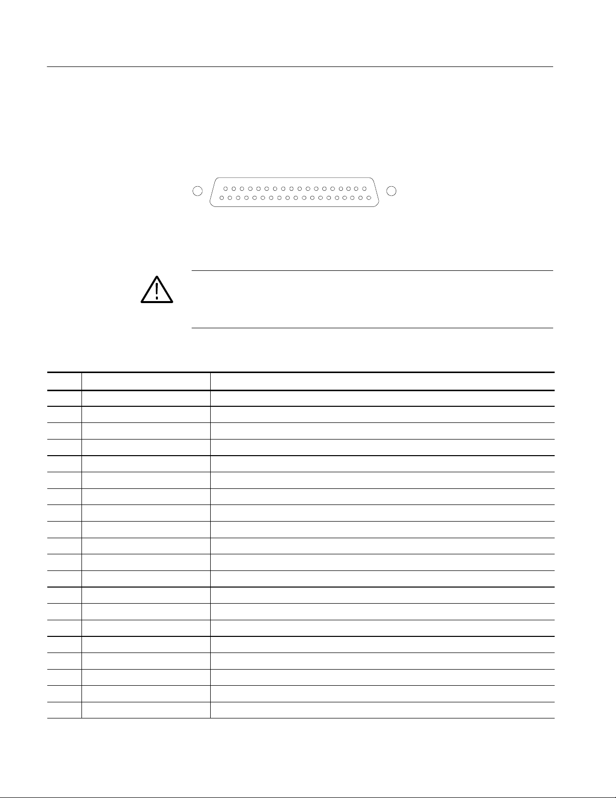
Operating Basics
Analog Input/Output
Connector
The Analog I/O connector is used to input and output analog signals. The
Analog I/O connector is a 37-pin, D-subminiature connector. Table 2--10 lists the
function of each pin in the connector.
20 37
119
Figure 2- 35: Analog I/O connect or pin diagram
CAUTION. Use care when connecting the Analog Audio Output. Refer to
Table 1--25 in Specifications, to ensure Audio Load and Output Power meet
specifications. Exceeding Analog Audio Output Power may result in damage to
the instrument.
Table 2- 10: Analog I/O connector pin-out
Pin Pin name Description
1 ANALOG_INPUT_LP0_A Balanced differential analog audio input: Left, positive, Pair 0, Line A
2 ANALOG_INPUT_LP0_B Balanced differential analog audio input: Left, positive, Pair 0, Line B
3 ANALOG_INPUT_RP0_A Balanced differential analog audio input: Right, positive, Pair 0, Line A
4 ANALOG_INPUT_RP0_B Balanced differential analog audio input: Right, positive, Pair 0, Line B
5 ANALOG_INPUT_LP1_A Balanced differential analog audio input: Left, positive, Pair 1, Line A
6 ANALOG_INPUT_LP1_B Balanced differential analog audio input: Left, positive, Pair 1, Line B
7 ANALOG_INPUT_RP1_A Balanced differential analog audio input: Right, positive, Pair 1, Line A
8 ANALOG_INPUT_RP1_B Balanced differential analog audio input: Right, positive, Pair 1, Line B
9 ANALOG_INPUT_LP2_A Balanced differential analog audio input: Left, positive, Pair 2, Line A
10 ANALOG_INPUT_LP2_B Balanced differential analog audio input: Left, positive, Pair 2, Line B
11 ANALOG_INPUT_RP2_A Balanced differential analog audio input: Right, positive, Pair 2, Line A
12 ANALOG_INPUT_RP2_B Balanced differential analog audio input: Right, positive, Pair 2, Line B
13 GND
14 ANA_OUT_LN0 Balanced differential analog audio output: Left, negative, Pair 0
15 ANA_OUT_RN0 Balanced differential analog audio output: Right, negative, Pair 0
16 ANA_OUT_LN1 Balanced differential analog audio output: Left, negative, Pair 1
17 ANA_OUT_RN1 Balanced differential analog audio output: Right, negative, Pair 1
18 ANA_OUT_LN2 Balanced differential analog audio output: Left, negative, Pair 2
19 ANA_OUT_RN2 Balanced differential analog audio output: Right, negative, Pair 2
20 ANALOG_INPUT_LN0_A Balanced differential analog audio input: Left, negative, Pair 0, Line A
2- 30
WVR610A & WVR611A Waveform Rasterizers Service Manual
Page 85

Table 2- 10: Analog I/O connector pin-out (Cont.)
Pin DescriptionPin name
21 ANALOG_INPUT_LN0_B Balanced differential analog audio input: Left, negative, Pair 0, Line B
22 ANALOG_INPUT_RN0_A Balanced differential analog audio input: Right, negative, Pair 0, Line A
23 ANALOG_INPUT_RN0_B Balanced differential analog audio input: Right, negative, Pair 0, Line B
24 ANALOG_INPUT_LN1_A Balanced differential analog audio input: Left, negative, Pair 1, Line A
25 ANALOG_INPUT_LN1_B Balanced differential analog audio input: Left, negative, Pair 1, Line B
26 ANALOG_INPUT_RN1_A Balanced differential analog audio input: Right, negative, Pair 1, Line A
27 ANALOG_INPUT_RN1_B Balanced differential analog audio input: Right, negative, Pair 1, Line B
28 ANALOG_INPUT_LN2_A Balanced differential analog audio input: Left, negative, Pair 2, Line A
29 ANALOG_INPUT_LN2_B Balanced differential analog audio input: Left, negative, Pair 2, Line B
30 ANALOG_INPUT_RN2_A Balanced differential analog audio input: Right, negative, Pair 2, Line A
31 ANALOG_INPUT_RN2_B Balanced differential analog audio input: Right, negative, Pair 2, Line B
32 ANA_OUT_LP0 Balanced differential analog audio output: Left, positive, Pair 0
33 ANA_OUT_RP0 Balanced differenti al anal og audio output: Right, posit ive, Pair 0
34 ANA_OUT_LP1 Balanced differential analog audio output: Left, positive, Pair 1
35 ANA_OUT_RP1 Balanced differenti al anal og audio output: Right, posit ive, Pair 1
36 ANA_OUT_LP2 Balanced differential analog audio output: Left, positive, Pair 2
37 ANA_OUT_RP2 Balanced differenti al anal og audio output: Right, posit ive, Pair 2
Operating Basics
The previous table identifies the Analog input/output connectors by left/right
pairs. The waveform rasterizer interface and the optional audio breakout cable
identifies the signals as a series of numbers from 1 to 6. Table 2--11 maps the
left/right pairs to the analog input number used in the interface and on the
breakout cable.
Table 2- 11: Channel pair to analog input mapping
Pair label Analog input
L0 1
R0 2
L1 3
R1 4
L2 5
R2 6
WVR610A & WVR611A Waveform Rasterizers Service Manual
2- 31
Page 86

Operating Basics
Connecting Signals. When connecting audio signals to the Analog Input
connectors, you can use either balanced or unbalanced signals. If you connect
unbalanced signals to the inputs, you do not have to ground the unused lead
(grounding the unused lead can reduce noise).
When connecting the Analog Output connectors, you can connect them as
balanced or unbalanced. However, if you connect the balanced outputs to an
unbalanced input, you must ground the unused lead. You can ground either lead.
NOTE. Note that grounding the unused lead does not attenuate the output but it
does halve the clipping level. Therefore, you must attenuate the output by at least
6 dB to avoid clipping. The output signal level in unbalanced mode is double the
signal level in balanced mode.
Units that have both analog and digital capability can have AES or embedded
inputs converted to analog and then routed to the six balanced outputs.
XGA Output Connector
This is the display output. The display resolution is 1024 x 768, in 16 colors.
The output is compatible with standard analog PC monitors, either CRT or
LCD-based. The REMOTE connector is a 15-pin D-type connector with socket
contacts. See Figure 2--36.
15
6
10
1115
Figure 2- 36: XGA output connector pin diagram
Table 2- 12: XGA connector pin-out
Pin Description Notes
1 Red Video
2 Green Video
3 Blue Video
2- 32
4 Not connected
5 Ground
6 Red Ground
7 Green Ground
WVR610A & WVR611A Waveform Rasterizers Service Manual
Page 87

Table 2- 12: XGA connector pin-out (Cont.)
Pin NotesDescription
8 Blue Ground
9 +5 V For monitor EEPROM
10 Not Connected
11 Not Connected
12 ID Bit Supports I2C polling
13 Horizontal Sync
14 Vertical Sync
15 ID Clock
Operating Basics
Ground Closure
The REMOTE connector interface uses ground closures for remote control and
indicating to external equipment when alarms have occurred. The input of LTC
is through the REMOTE connector. The REMOTE connector is a 15-pin D-type
connector with socket contacts. See Figure 2--37 and Table 2--13.
81
915
Figure 2- 37: REMOTE connector pin diagram
Table 2- 13: REMOTE connector pin-out
Pin Description Direction Notes
1 Reserved for future use -- --
2 GND
3 Reserved for future use -- --
4 Reserved for future use -- --
5 Preset 1 IN Recall Preset 1
6 GND
7 +Time Code IN LTC (longitudinal time code) input.
8 --Time Code IN
WVR610A & WVR611A Waveform Rasterizers Service Manual
2- 33
Page 88

Operating Basics
thePresetsignalscausestheassociated
waveformraster
izer
b
y
Table 2- 13: REMOTE connector pin-out (Cont.)
Pin NotesDirectionDescription
9 Output OUT This line goes to ground when asserted. It
is asserted when an alarm occurs, if
enabled.
10 Reserved for future use -- --
11 Reserved for future use -- --
12 Reserved for future use -- --
13 Preset 2 IN Recall f ront -panel presets. Asserting one of
Ethernet Connector
14 Preset 3 IN
15 Preset 4 IN
front-panel preset to be applied to the
.Assertapin
connecting it to ground.
The waveform rasterizer provides a 10/100 BaseT Ethernet interface. The
Ethernet connector is a standard RJ-45 connector. See Figure 2--38.
Green LEDYellow LED
Figure 2- 38: RJ-45 Ethernet connector
The connector includes two LEDs for indicating status. See Table 2--14.
Table 2- 14: Ethernet connector LEDs
LED color Meaning
Green Connection is active
Yellow ON = 100 Mb transmission rate
OFF = 10 Mb transmission rate
2- 34
WVR610A & WVR611A Waveform Rasterizers Service Manual
Page 89

Table 2--15 provides a pin-out for the RJ-45 connector.
Table 2- 15: Ethernet connector pin-out
Pin Pin name Description
1 TX_D1+ Transceive Data+
2 TX_D1-- Transceive Data--
3 RX_D2+ Receive Data+
4 BI_D3+ Bi-directional Data+
5 BI_D3-- Bi-directional Data--
6 RX_D2-- Receive Data--
7 BI_D4+ Bi-directional Data+
8 BI_D4-- Bi-directional Data--
Operating Basics
WVR610A & WVR611A Waveform Rasterizers Service Manual
2- 35
Page 90

Operating Basics
2- 36
WVR610A & WVR611A Waveform Rasterizers Service Manual
Page 91

Changing Instrument Settings
Use the Configuration menu to adjust instrument settings that are not specific to
a tile. The Configuration menu settings are instrument settings that you will
generally set when you first install the waveform rasterizer, and then change only
occasionally afterward.
SDI Input Settings
The SDI Input settings specify how SDI inputs are displayed. See Table 2--16.
To change the SDI Input settings:
1. Press CONFIG to display the Configuration menu.
2. Select SDI Input to display the submenu.
3. Press the right-arrow key to change the menu focus to the SDI Input
submenu.
4. Select the desired setting and change the setting as needed.
Input Format
Strip EAV/SAV/ANC
5. After changing the setting, press CONFIG to remove the Configuration
menu.
Table 2- 16: SDI input settings
Setting Choices / Range
Input Format Auto / 525 / 625
Stri p EAV/SAV / ANC On / Off
Chroma Offset/Align
NTSC Setup 0%/7.5%
Specifies the format of the input signal. Auto allows the input to automatically
detect the input format, or it can be configured to run only in 525 or 625 line
mode. The manual mode (525 or 625) may be useful for signals with errors.
Determines whether the EAV and SAV timing references or the ancillary data,
such as audio, are visible in the Waveform display. Since these data values are
not band limited, they usually ring when displayed through the video waveform
filters.
WVR610A & WVR611A Waveform Rasterizers Service Manual
2- 37
Page 92

Changing Instrument Settings
Chroma
NTSC Setup
Determines the vertical position of the color difference signals. If you select
Align, the chroma zero levels are aligned with the luminance zero level. The
color difference signals will extend below luma, but Gain will expand around the
zero levels. If you select Offset a 350 mV positive offset is added to the PbPr
channels. This does not affect the transcoded RGB display or the picture monitor
output signal.
Specifies how the SDI-->Composite and Arrowhead display will be setup.
Composite Input Settings
The Composite Input settings specify how composite inputs are displayed. See
Table 2--17.
To change the Composite Input settings:
1. Press CONFIG to display the Configuration menu.
2. Select Composite Input.
3. Use the navigation keys to change the menu focus to the submenu.
Input Format
4. Select the desired setting and change the setting as needed.
5. After changing the setting, press CONFIG to remove the Configuration
menu.
Table 2- 17: Composite input settings
Setting Choices / Range
Input Format Auto / NTSC / PAL
Sync AFC Speed Fast / Slow
DC Restore Fast / Slow /Off
NTSC Setup On / Off
PAL Ve ctor Normal / V+
Specifies the format of the input composite signal. In Auto, the waveform
rasterizer automatically detects the correct format. This setting is useful when
you occasionally changes the input format. If you always monitor the same
signal format, you can specify NTSC or PAL.
2- 38
WVR610A & WVR611A Waveform Rasterizers Service Manual
Page 93

Changing Instrument Settings
Sync AFC Speed
DC Restore
NTSC Setup
The Sync AFC Speed sets the ability of the loop to follow changes in the
external reference signal. “Fast” can track signals with more line rate variation.
“Slow” has lower jitter.
Applies a voltage to the signal to keep one point on the waveform at a fixed DC
level. This makes taking measurements easier when the DC level of the
waveform shifts due to changes in signal content. Setting choices are Fast, Slow,
and Off.
H Select Off when you wish to see the DC offset in the signal. Off cancels the
operation of the DC Restore circuitry.
H Select Slow when you wish to remove DC offset from the signal but you still
want to see hum.
H Select Fast when you want to remove the effects of hum and offset from the
signal.
The NTSC Setup setting optimizes the operation of the WVR610A &
WVR611A for NTSC signals with and without set up. For example, this setting
changes the scaling of the vector bar targets.
PAL Vector
When V+ is chosen, the phase reference of the --V lines is inverted, then shown
as an overlay on the +V lines to provide a comparison display.
External Reference Setting
The External Reference setting specifies the allowed formats of the signal on the
EXT REF IN connector. See Table 2--18.
To change the External Reference settings:
1. Press CONFIG to display the Configuration menu.
2. Use the GENERAL knob or the up/down arrow keys to select External
3. Use the navigation keys to change the menu focus to the External Ref
4. Select the Lock to Standard setting and change the setting as needed.
5. After changing the setting, press CONFIG to remove the Configuration
Ref.
submenu.
menu.
WVR610A & WVR611A Waveform Rasterizers Service Manual
2- 39
Page 94

Changing Instrument Settings
Table 2- 18: External reference settings
Setting Choices
Lock to Standard Auto / NTSC / PAL
Sync AFC Speed Fast / Slow
Lock to Standard
Sync AFC Speed
Sets the external reference format. In Auto, the waveform rasterizer automatically detects the correct format. This setting is useful when you occasionally change
the input format for the external reference signal. If you always use the same
external reference signal format, you can specify NTSC or PAL.
The Sync AFC Speed sets the ability of the loop to follow changes in the
external reference signal. “Fast” can track signals with more line rate variation.
“Slow” has lower jitter.
NOTE. When using an SDI input with an external reference, an input signal
time--base variation outside the specified range may be shown as a reference
unlock on the status bar and error logs.
Analog Audio Displays Settings
The Audio Display submenu provides access to parameters that control meter
ballistics, various meter characteristics such as Peak Hold Time, the number of
consecutive samples required to trigger various alarms, and other settings.
Table 2--19 lists the settings for audio displays.
2- 40
To change the audio display settings:
1. Press CONFIG to display the Configuration menu.
2. Select Analog Audio Displays. Use the right-key to change to menu focus
to the Analog Audio Displays submenu.
3. Select the desired setting and change the setting as desired.
4. After changing the setting, press CONFIG to remove the Configuration
menu.
WVR610A & WVR611A Waveform Rasterizers Service Manual
Page 95

Changing Instrument Settings
Table 2- 19: Analog Audio display settings
Setting Values
Ballistics True Peak / PPM Type 1 / PPM Type 2 / VU
Default: True Peak
Peak Hold Time Range: 0 to 10 seconds
Default: 2 seconds
Peak Hold Segment On / Off
Default: On
Set 0dB Mark To: Top of Scale / Peak Program Level / Test Level
Default: Test Level
Peak Program Level 24 to --6 dBu
Default: 10 dBu
Test Level 24 to --6 dBu
Default: 0 dBu
Meter Scaling Normal (Default)
Custom Height: 10 to 90 dB (Default: 70 dB)
Custom Offset: --20 to 0 dB (Default: 0 dB)
GraticuleStepSize:3to10dB(Default:
10 dB)
Set Meter Type to: dBu / DIN (IEC Type 1) / VU / Nordic (IEC
Type IIb) / IEEE PPM
Silence Level Range: --16 to --46 dBu
Default: --26 dB
Duration for Silence Range: 0 to 60 seconds
Default: 10 seconds
Over Level Range: 24 to --6 dB
Default: 10 dB
Duration for Over Range: 0 to 30 seconds
Default: 1 second
Error Hold Time Range: 0 to 30 seconds
WVR610A & WVR611A Waveform Rasterizers Service Manual
Default: 2 seconds
2- 41
Page 96

Changing Instrument Settings
Table 2- 19: Analog Audio display settings (Cont.)
Setting Values
Correlation Meter Speed Range: 1 to 30
Default: 8
Lissajous AGC On / Off
Default: On
Ballistics
Specifies the response characteristics of the level meters. Choices are True Peak,
PPM (Peak Program Meter) Type 1 and Type 2, and VU.
H True Peak -- Show actual signal peaks regardless of their duration. Rise
times are essentially instantaneous. Fall time is like PPM Type 2, and
requires 2.8 seconds to fall 20 dB. The in-bar peak indicator will persist at
the peak level for the “Peak Hold Time”. When True Peak ballistics are
selected, the display designation is True Peak Ballistics.
H PPM Type 1-- Response equivalent to IEC Type I (essentially the same as
DIN 45406 and Nordic N--9). The PPM Type 1 has a slightly faster attack
time and a faster return time than Type 2, requiring 1.7 seconds to fall 20 dB
as opposed to 2.8 seconds for Type II. When PPM Type 1 ballistics are
selected, the display designation is PPM Type 1 Ballistics.
H PPM Type 2--Response equivalent to IEC Type II (the same as defined in
IEEE Std 152--1991). The PPM Type 2 has a slightly slower attack time and
a slower return time than Type 1, requiring 2.8 seconds to fall 20 dB as
opposed to 1.7 seconds for Type 1. When PPM Type 2 ballistics are selected,
the display designation is PPM Type 2 Ballistics.
H VU -- A VU meter as defined by IEEE Std. 152-1991, but with an extended
dB-linear scale. The meter bars will also contain true peak indicators when
VU is selected. The display designation of this setting is VU Ballistics.
2- 42
Peak Hold Time
Peak Hold Segment
Set 0 dB Mark To
Specifies the number of seconds that the True Peak Indicator remains at the most
recent peak level.
Switches the Peak Hold Indicator on or off.
Numbers the meter scale relative to Top of Scale or to one of the two user-adjustable levels. When the zero mark is set to either Peak Program or Test level, the
scale units are dBr, relative to the 0 dB level; units above the selected 0 dB mark
are positive, while units below it are negative.
WVR610A & WVR611A Waveform Rasterizers Service Manual
Page 97

Changing Instrument Settings
Peak Program Level
Test Level
Meter Scaling
Set Meter Type to:
Sets the maximum desired level for monitored programs. The meter bars change
to red above the Peak Program Level.
Sets as the test or “line up” level for your system. The meter bars change to
yellow between the Test and Peak Program Levels.
Sets the scaling for the level meters. Meter scaling can be set to Normal or
customized by setting up to three parameters: Custom Height, Custom Offset and
Graticule Size. At the Normal setting, the meter scale is set to a 70 dB range,
with the actual values at the top and bottom of the meter depending on the
setting for Set 0dB Mark to:. When you select one of the custom parameters, all
are enabled. When using Custom Height, the range of the meters can be set from
10 -- 90 dB. When using Custom Offset, you are setting the location of a
“window” on the bar, where the size of the window is set by the Custom Height
setting. The Custom Offset setting, in effect, moves the window up and down the
range of the level meter. The Graticule Size setting specifies the difference in dB
between graticule tic marks. The difference between tic marks can be set from
3dBto10dB,exceptforVUwhichissetat3dB.
Sets parameters defining meter characteristics to conform with audio meter types
standardized in the industry. The characteristics of each meter type are shown in
Table 2--20.
Silence Level
Duration for Silence
Table 2- 20: Characteristics of meter types
Scale
Meter Type Ballistic 0dBMark Test PPL
dBu PPM Type II Test 0dBu 10 dBu 70 dB 0dB 10 dB
DIN
(IEC Type 1)
VU VU Tes t 0dBu 0dBu 24 dB 21 dB 1dB
Nordic
(IEC Type IIb)
IEEE PPM PPM Type II PPL 0dBu
PPM Type I PPL -- 3 d B u
(--9 dBr)
PPM Type II Test 0dBu 6dBu 54 dB 12 dB 6dB
(--8 dBr)
6dBu
(0 dBr)
8dBu
(0 dBr)
Height
55 dB 13 dB 5dB
32 dB 8dB 4dB
Scale
Offset
Scale
Step
Sets the audio level below which the signal is considered silent. This value is
used to trigger an on-screen indicator and alarms.
Specifies how long the audio level must be below the Silence Level before an
alarm is triggered. Setting the duration to “0” seconds disables the alarm.
WVR610A & WVR611A Waveform Rasterizers Service Manual
2- 43
Page 98

Changing Instrument Settings
Over Level
Duration for Over
Error Hold Time
Correlation Meter Speed
Lissajous AGC
Specifies the audio level above which the signal is considered “over”. This
setting is used to trigger on-screen indicators and alarms.
Specifies how long the audio level must be above the Over Level before an alarm
will be triggered.
Specifies the length of time the in-bar error messages are displayed after the error
has been removed.
Determines how quickly the meter reacts to changes in phase relationship. The
meter reading is actually an average of correlation over time and this setting
determines how many samples are used to calculate the average. Lower settings
result in a faster meter response. Experiment to find the setting that best fits your
needs. The default setting is 8, which is 1.5 seconds.
When On, allows the Lissajous or Phase display to change gain and keep the
display well scaled. When Off, puts the display in fixed gain mode with the Peak
Program level at the perimeter of the active area.
NOTE. The audio pop-up menu allows selection of input and allows the optional
phase display to be added to the audio tile.
Digital Audio Displays Settings
The Digital Audio Display submenu provides access to parameters that control
meter ballistics, various meter characteristics such as Peak Hold Time, the
number of consecutive samples required to trigger various alarms, and other
settings. Table 2--19 lists the settings for audio displays.
To change the audio display settings:
1. Press CONFIG to display the Configuration menu.
2. Select Digital Audio Displays. Use the right-key to change to menu focus to
the Digital Audio Displays submenu.
3. Select the desired setting and change the setting as desired.
4. After changing the setting, press CONFIG to remove the Configuration
menu.
2- 44
WVR610A & WVR611A Waveform Rasterizers Service Manual
Page 99

Changing Instrument Settings
Table 2- 21: Digital Audio display sett ings
Setting Values
Ballistics True Peak / PPM Type 1 / PPM Type 2 / VU
Default: True Peak
Peak Hold Time Range: 0 to 10 seconds
Default: 2 seconds
Peak Hold Segment On / Off
Default: On
Set 0dB Mark To: Top of Scale / Peak Program Level / Test Level
Default: Peak Program Level
Peak Program Level 0to--30dBFS
Default: --8 dB
Test Level 0to--30dBFS
Default: --18 dB
Meter Scaling Normal (Default)
Custom Height: 10 to 90 dB (Default: 70 dB)
Custom Offset: --20 to 0 dB (Default: 0 dB)
GraticuleStepSize:3to10dB(Default:
10 dB)
# Samples for Clip Range: 0 to 100
Default: 1
# Sample for Mute Range: 0 to 100
Default: 10 consecutive
Silence Level Range: --70 to --40 dBFS
Default: --60 dB
Duration for Silence Range: 0 to 60 seconds
Default: 10 seconds
Over Level Range: --20 to 0 dBFS
Default: --8 dB
Duration for Over Range: 0 to 30 seconds
Error Hold Time Range: 0 to 30 seconds
WVR610A & WVR611A Waveform Rasterizers Service Manual
Default: 1 second
Default: 2 seconds
2- 45
Page 100

Changing Instrument Settings
Table 2- 21: Digital Audio display sett ings (Cont.)
Setting Values
Correlation Meter Speed Range: 1 to 30
Default: 8
Lissajous AGC On / Off
Default: On
Ballistics
Specifies the response characteristics of the level meters. Choices are True Peak,
PPM (Peak Program Meter) Type 1 and Type 2, and VU.
H True Peak -- Show actual signal peaks regardless of their duration. Rise
times are essentially instantaneous. Fall time is like PPM Type 2, and
requires 2.8 seconds to fall 20 dB. The in-bar peak indicator will persist at
the peak level for the “Peak Hold Time”. When True Peak ballistics are
selected, the display designation is True Peak Ballistics.
H PPM Type 1-- Response equivalent to IEC Type I (essentially the same as
DIN 45406 and Nordic N--9). The PPM Type 1 has a slightly faster attack
time and a faster return time than Type 2, requiring 1.7 seconds to fall 20 dB
as opposed to 2.8 seconds for Type II. When PPM Type 1 ballistics are
selected, the display designation is PPM Type 1 Ballistics.
H PPM Type 2--Response equivalent to IEC Type II (the same as defined in
IEEE Std 152--1991). The PPM Type 2 has a slightly slower attack time and
a slower return time than Type 1, requiring 2.8 seconds to fall 20 dB as
opposed to 1.7 seconds for Type 1. When PPM Type 2 ballistics are selected,
the display designation is PPM Type 2 Ballistics.
H VU -- A VU meter as defined by IEEE Std. 152-1991, but with an extended
dB-linear scale. The meter bars will also contain true peak indicators when
VU is selected. The display designation of this setting is VU Ballistics.
2- 46
Peak Hold Time
Peak Hold Segment
Set 0 dB Mark To
Specifies the number of seconds that the True Peak Indicator remains at the most
recent peak level.
Switches the Peak Hold Indicator on or off.
Numbers the meter scale relative to Top of Scale or to one of the two user-adjustable levels. When the zero mark is set to either Peak Program or Test level, the
scale units are dBr, relative to the 0 dB level; units above the selected 0 dB mark
are positive, while units below it are negative.
WVR610A & WVR611A Waveform Rasterizers Service Manual
 Loading...