

Page 1

Service Manual
WVR500
Waveform/Vector Monitor
070-8897-01
Warning
The servicing instructions are for use by qualified
personnel only. To avoid personal injury, do not
perform any servicing unless you are qualified to
do so. Refer to all safety summaries prior to performing service.
Page 2

Copyright T ektronix, Inc. All rights reserved.
T ektronix products are covered by U.S. and foreign patents, issued and pending. Information in this publication supercedes
that in all previously published material. Specifications and price change privileges reserved.
Printed in the U.S.A.
T ektronix, Inc., P.O. Box 1000, Wilsonville, OR 97070–1000
TEKTRONIX and TEK are registered trademarks of T ektronix, Inc.
Page 3

WARRANTY
T ektronix warrants that the products that it manufactures and sells will be free from defects in materials and workmanship
for a period of three (3) years from the date of shipment. If a product proves defective during this warranty period,
T ektronix, at its option, either will repair the defective product without charge for parts and labor, or will provide a
replacement in exchange for the defective product.
In order to obtain service under this warranty, Customer must notify Tektronix of the defect before the expiration of the
warranty period and make suitable arrangements for the performance of service. Customer shall be responsible for
packaging and shipping the defective product to the service center designated by T ektronix, with shipping charges prepaid.
T ektronix shall pay for the return of the product to Customer if the shipment is to a location within the country in which the
T ektronix service center is located. Customer shall be responsible for paying all shipping charges, duties, taxes, and any
other charges for products returned to any other locations.
This warranty shall not apply to any defect, failure or damage caused by improper use or improper or inadequate
maintenance and care. T ektronix shall not be obligated to furnish service under this warranty a) to repair damage resulting
from attempts by personnel other than T ektronix representatives to install, repair or service the product; b) to repair
damage resulting from improper use or connection to incompatible equipment; c) to repair any damage or malfunction
caused by the use of non-T ektronix supplies; or d) to service a product that has been modified or integrated with other
products when the effect of such modification or integration increases the time or difficulty of servicing the product.
THIS WARRANTY IS GIVEN BY TEKTRONIX IN LIEU OF ANY OTHER WARRANTIES, EXPRESS OR
IMPLIED. TEKTRONIX AND ITS VENDORS DISCLAIM ANY IMPLIED WARRANTIES OF
MERCHANTABILITY OR FITNESS FOR A P ARTICULAR PURPOSE. TEKTRONIX’ RESPONSIBILITY TO
REP AIR OR REPLACE DEFECTIVE PRODUCTS IS THE SOLE AND EXCLUSIVE REMEDY PROVIDED TO
THE CUSTOMER FOR BREACH OF THIS WARRANTY. TEKTRONIX AND ITS VENDORS WILL NOT BE
LIABLE FOR ANY INDIRECT , SPECIAL, INCIDENTAL, OR CONSEQUENTIAL DAMAGES IRRESPECTIVE
OF WHETHER TEKTRONIX OR THE VENDOR HAS ADVANCE NOTICE OF THE POSSIBILITY OF SUCH
DAMAGES.
Page 4

Service Assurance
If you have not already purchased Service Assurance for this product, you may do so at any time during the product’s
warranty period. Service Assurance provides Repair Protection and Calibration Services to meet your needs.
Repair Protection extends priority repair services beyond the product’s warranty period; you may purchase up to three
years of Repair Protection.
Calibration Services provide annual calibration of your product, standards compliance and required audit documentation,
recall assurance, and reminder notification of scheduled calibration. Coverage begins upon registration; you may purchase
up to five years of Calibration Services.
Service Assurance Advantages
Priced well below the cost of a single repair or calibration
Avoid delays for service by eliminating the need for separate purchase authorizations from your company
Eliminates unexpected service expenses
For Information and Ordering
For more information or to order Service Assurance, contact your T ektronix representative and provide the information
below . Service Assurance may not be available in locations outside the United States of America.
Name VISA or Master Card number and expiration
Company date or purchase order number
Address Repair Protection (1,2, or 3 years)
City , State, Postal code Calibration Services (1,2,3,4, or 5 years)
Country Instrument model and serial number
Phone Instrument purchase date
Page 5

Table of Contents
Specifications
Operating Information
General Safety Summary vii. . . . . . . . . . . . . . . . . . . . . . . . . . . . . . . . . . . .
Service Safety Summary ix. . . . . . . . . . . . . . . . . . . . . . . . . . . . . . . . . . . . .
Preface xi. . . . . . . . . . . . . . . . . . . . . . . . . . . . . . . . . . . . . . . . . . . . . . . . . . .
Specifications 1–1. . . . . . . . . . . . . . . . . . . . . . . . . . . . . . . . . . . . . . . . . . . . . .
Product Description 1–1. . . . . . . . . . . . . . . . . . . . . . . . . . . . . . . . . . . . . . . . . . . . . . .
Characteristics T ables 1–2. . . . . . . . . . . . . . . . . . . . . . . . . . . . . . . . . . . . . . . . . . . . . .
Installation 2–1. . . . . . . . . . . . . . . . . . . . . . . . . . . . . . . . . . . . . . . . . . . . . . . .
Mechanical Installation 2–1. . . . . . . . . . . . . . . . . . . . . . . . . . . . . . . . . . . . . . . . . . . .
Electrical Installation 2–3. . . . . . . . . . . . . . . . . . . . . . . . . . . . . . . . . . . . . . . . . . . . . .
Operating Instructions 2–7. . . . . . . . . . . . . . . . . . . . . . . . . . . . . . . . . . . . . .
Front Panel Controls 2–7. . . . . . . . . . . . . . . . . . . . . . . . . . . . . . . . . . . . . . . . . . . . . .
Special Operating Modes 2–10. . . . . . . . . . . . . . . . . . . . . . . . . . . . . . . . . . . . . . . . . . .
On-Screen Readout 2–11. . . . . . . . . . . . . . . . . . . . . . . . . . . . . . . . . . . . . . . . . . . . . . .
Menu Operation 2–12. . . . . . . . . . . . . . . . . . . . . . . . . . . . . . . . . . . . . . . . . . . . . . . . . .
Theory of Operation
Theory of Operation 3–1. . . . . . . . . . . . . . . . . . . . . . . . . . . . . . . . . . . . . . . .
Performance Verification
Performance Verification 4–1. . . . . . . . . . . . . . . . . . . . . . . . . . . . . . . . . . . .
Required Equipment List 4–1. . . . . . . . . . . . . . . . . . . . . . . . . . . . . . . . . . . . . . . . . . .
Short-Form Performance Verification 4–3. . . . . . . . . . . . . . . . . . . . . . . . . . . . . . . . .
Long-Form Performance Verification 4–4. . . . . . . . . . . . . . . . . . . . . . . . . . . . . . . . .
Adjustment Procedures
Adjustment Procedures 5–1. . . . . . . . . . . . . . . . . . . . . . . . . . . . . . . . . . . . . .
Required Equipment List 5–1. . . . . . . . . . . . . . . . . . . . . . . . . . . . . . . . . . . . . . . . . . .
Short-Form Adjustment Procedures 5–3. . . . . . . . . . . . . . . . . . . . . . . . . . . . . . . . . . .
Long-Form Adjustment Procedures 5–3. . . . . . . . . . . . . . . . . . . . . . . . . . . . . . . . . . .
WVR500 Waveform/Vector Monitor Service Manual
i
Page 6

Table of Contents
Maintenance
Options
Replaceable Parts
Maintenance 6–1. . . . . . . . . . . . . . . . . . . . . . . . . . . . . . . . . . . . . . . . . . . . . . .
Service Options 6–1. . . . . . . . . . . . . . . . . . . . . . . . . . . . . . . . . . . . . . . . . . . . . . . . . .
Preparation 6–3. . . . . . . . . . . . . . . . . . . . . . . . . . . . . . . . . . . . . . . . . . . . . . . . . . . . . .
Preventive Maintenance 6–4. . . . . . . . . . . . . . . . . . . . . . . . . . . . . . . . . . . . . . . . . . . .
Repackaging Instructions 6–6. . . . . . . . . . . . . . . . . . . . . . . . . . . . . . . . . . . . . . . . . . .
Removal and Replacement 6–7. . . . . . . . . . . . . . . . . . . . . . . . . . . . . . . . . . .
Troubleshooting Procedures 6–17. . . . . . . . . . . . . . . . . . . . . . . . . . . . . . . . . .
Required Equipment 6–17. . . . . . . . . . . . . . . . . . . . . . . . . . . . . . . . . . . . . . . . . . . . . . .
Troubleshooting Flowchart 6–17. . . . . . . . . . . . . . . . . . . . . . . . . . . . . . . . . . . . . . . . .
Options 7–1. . . . . . . . . . . . . . . . . . . . . . . . . . . . . . . . . . . . . . . . . . . . . . . . . . .
Power Cord Options 7–1. . . . . . . . . . . . . . . . . . . . . . . . . . . . . . . . . . . . . . . . . . . . . . .
Replaceable Parts 8–1. . . . . . . . . . . . . . . . . . . . . . . . . . . . . . . . . . . . . . . . . .
Parts Ordering Information 8–1. . . . . . . . . . . . . . . . . . . . . . . . . . . . . . . . . . . . . . . . .
Using the Replaceable Parts List 8–2. . . . . . . . . . . . . . . . . . . . . . . . . . . . . . . . . . . . .
ii
WVR500 Waveform/Vector Monitor Service Manual
Page 7

List of Figures
Table of Contents
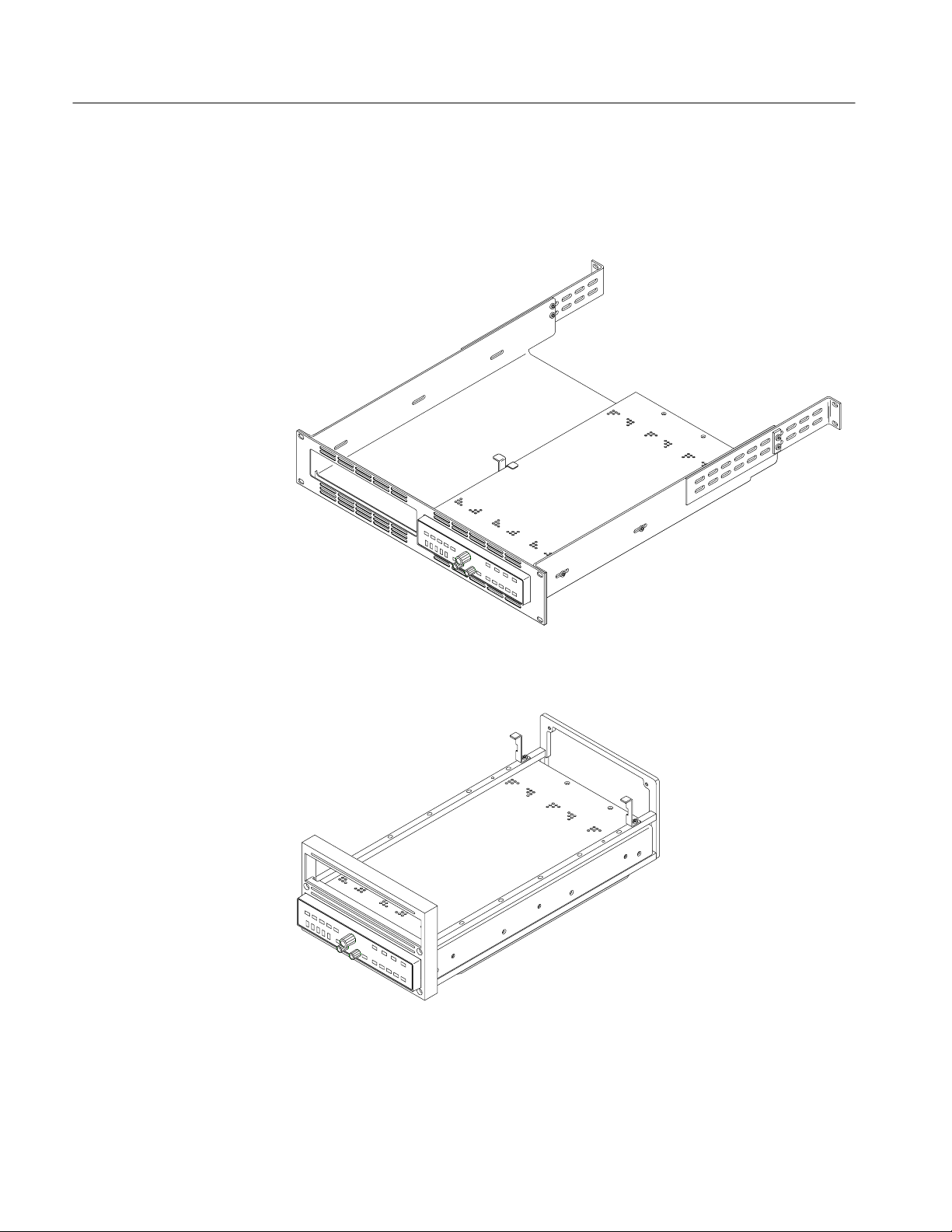
Figure 2–1: The TVGF13 side-by-side rack adapter 2–2. . . . . . . . . . . . . .
Figure 2–2: The TVGF14 dual half-rack adapter 2–2. . . . . . . . . . . . . . . .
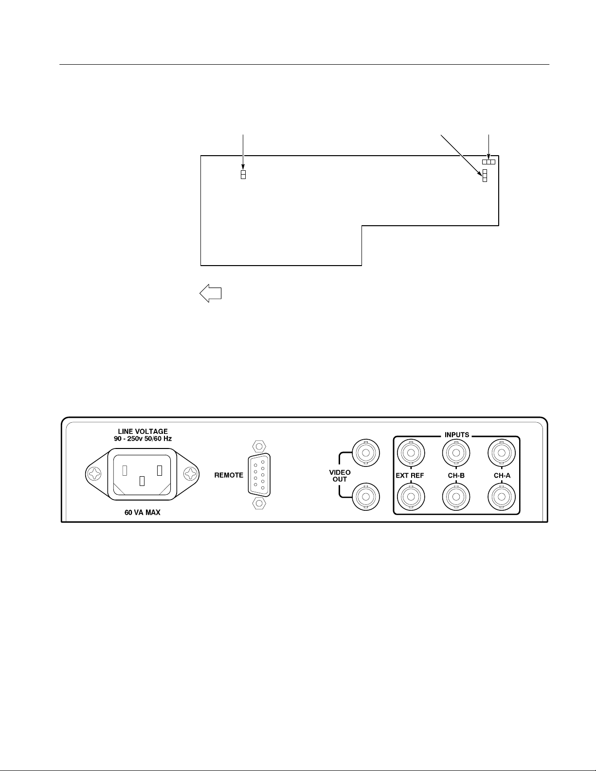
Figure 2–3: Operational jumper locations. 2–5. . . . . . . . . . . . . . . . . . . . . .
Figure 2–4: WVR500 monitor rear panel 2–5. . . . . . . . . . . . . . . . . . . . . . .
Figure 2–5: WVR500 monitor front panel 2–8. . . . . . . . . . . . . . . . . . . . . .
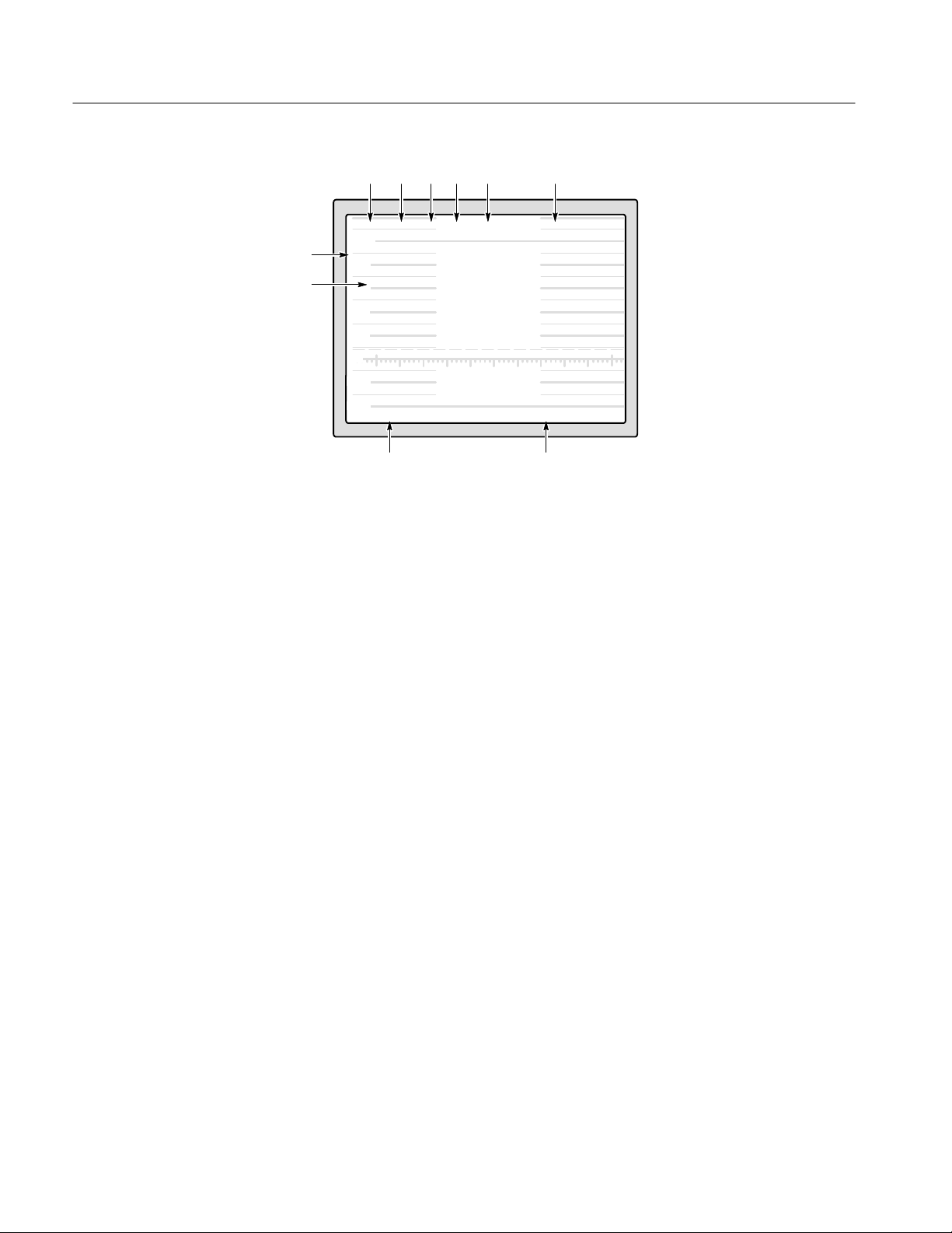
Figure 2–6: On-screen readout display 2–12. . . . . . . . . . . . . . . . . . . . . . . . .
Figure 2–7: Typical menu display 2–13. . . . . . . . . . . . . . . . . . . . . . . . . . . . .
Figure 3–1: Front Panel board block diagram 3–1. . . . . . . . . . . . . . . . . . .
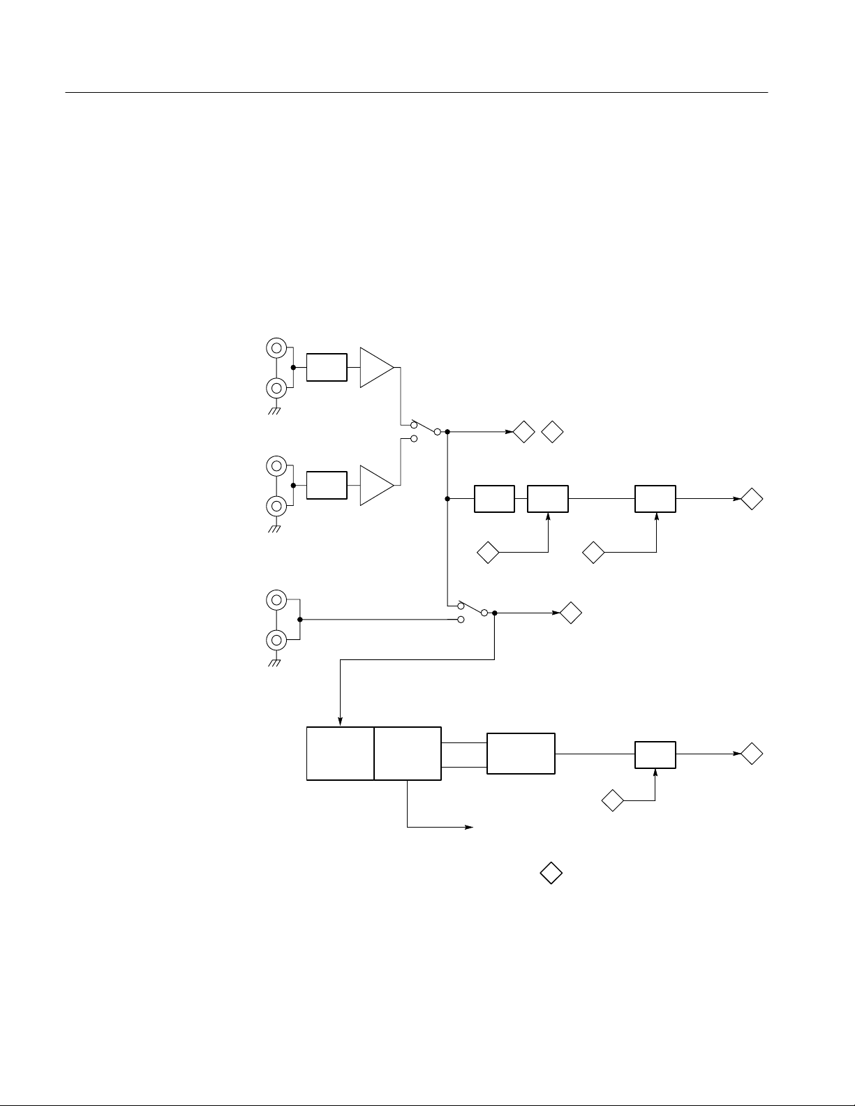
Figure 3–2: Partial Main board block diagram 3–2. . . . . . . . . . . . . . . . . .
Figure 3–3: Subcarrier generator block diagram 3–3. . . . . . . . . . . . . . . .
Figure 3–4: Vector demodulators block diagram 3–3. . . . . . . . . . . . . . . . .
Figure 3–5: Microprocessor circuitry block diagram 3–4. . . . . . . . . . . . .
Figure 3–6: Analog control ciruitry block diagram 3–5. . . . . . . . . . . . . . .
Figure 3–7: FPGA and RAMDAC circuitry block diagram 3–6. . . . . . . .
Figure 3–8: Rasterizer block diagram 3–7. . . . . . . . . . . . . . . . . . . . . . . . . .
Figure 3–9: Video out and power supply block diagram 3–8. . . . . . . . . . .
Figure 3–10: Serial Filter board block diagram 3–8. . . . . . . . . . . . . . . . . .
Figure 4–1: –3 dB marks on the vector graticule 4–16. . . . . . . . . . . . . . . . .
Figure 5–1: Location of the Calibration Enable jumper 5–4. . . . . . . . . . .
Figure 5–2: NTSC graticule showing the correct adjustment of
vector gain and symmetry 5–13. . . . . . . . . . . . . . . . . . . . . . . . . . . . . . . .
Figure 6–1: Removing the top cover 6–8. . . . . . . . . . . . . . . . . . . . . . . . . . .
Figure 6–2: Removing the front-panel assembly 6–11. . . . . . . . . . . . . . . . .
Figure 6–3: Removing the Front Panel board 6–10. . . . . . . . . . . . . . . . . . .
Figure 6–4: Removing the power supply 6–10. . . . . . . . . . . . . . . . . . . . . . . .
Figure 6–5: Removing the Serial Filter board 6–12. . . . . . . . . . . . . . . . . . .
Figure 6–6: Removing the line filter 6–13. . . . . . . . . . . . . . . . . . . . . . . . . . .
Figure 6–7: Main board BNC connectors 6–14. . . . . . . . . . . . . . . . . . . . . . .
Figure 6–8: Removing the Main board 6–15. . . . . . . . . . . . . . . . . . . . . . . . .
Figure 6–9: A2 and A3 circuit board test point locations 6–17. . . . . . . . . .
Figure 6–10: Troubleshooting flowchart 6–18. . . . . . . . . . . . . . . . . . . . . . . .
WVR500 Waveform/Vector Monitor Service Manual
iii
Page 8

Table of Contents
List of Tables
Figure 8–1: WVR 500 monitor exploded view 8–5. . . . . . . . . . . . . . . . . . .
Table 1–1: Vertical deflection system 1–3. . . . . . . . . . . . . . . . . . . . . . . . . .
Table 1–2: DC restoration 1–5. . . . . . . . . . . . . . . . . . . . . . . . . . . . . . . . . . .
Table 1–3: Horizontal deflection system 1–5. . . . . . . . . . . . . . . . . . . . . . . .
Table 1–4: Synchronization 1–6. . . . . . . . . . . . . . . . . . . . . . . . . . . . . . . . . .
Table 1–5: Vector mode 1–7. . . . . . . . . . . . . . . . . . . . . . . . . . . . . . . . . . . . .
Table 1–6: Power source 1–8. . . . . . . . . . . . . . . . . . . . . . . . . . . . . . . . . . . .
Table 1–7: Physical characteristics 1–8. . . . . . . . . . . . . . . . . . . . . . . . . . . .
Table 1–8: Environmental characteristics 1–8. . . . . . . . . . . . . . . . . . . . . .
Table 1–9: Certifications and compliances 1–9. . . . . . . . . . . . . . . . . . . . . .
Table 2–1: Operational jumper selections 2–4. . . . . . . . . . . . . . . . . . . . . .
Table 4–1: Verification required test equipment 4–1. . . . . . . . . . . . . . . . .
Table 4–2: Short-form performance verification 4–3. . . . . . . . . . . . . . . .
Table 5–1: Adjustment required test equipment 5–1. . . . . . . . . . . . . . . . .
Table 5–2: Short-form adjustment procedures 5–3. . . . . . . . . . . . . . . . . .
Table 5–3: Power supply test point voltages 5–5. . . . . . . . . . . . . . . . . . . .
Table 6–1: Required tools for module removal and replacement 6–7. . . .
Table 6–2: Required equipment for troubleshooting 6–17. . . . . . . . . . . . .
Table 8–1: Replaceable parts list column descriptions 8–2. . . . . . . . . . . .
iv
WVR500 Waveform/Vector Monitor Service Manual
Page 9

General Safety Summary
Review the following safety precautions to avoid injury and prevent damage to
this product or any products connected to it.
Only qualified personnel should perform service procedures.
Injury Precautions
Use Proper Power Cord. To avoid fire hazard, use only the power cord specified
for this product.
Avoid Electric Overload. To avoid electric shock or fire hazard, do not apply a
voltage to a terminal that is outside the range specified for that terminal.
Avoid Overvoltage. To avoid electric shock or fire hazard, do not apply potential
to any terminal, including the common terminal, that varies from ground by
more than the maximum rating for that terminal.
Avoid Electric Shock. To avoid injury or loss of life, do not connect or disconnect
probes or test leads while they are connected to a voltage source.
Ground the Product. This product is grounded through the grounding conductor
of the power cord. To avoid electric shock, the grounding conductor must be
connected to earth ground. Before making connections to the input or output
terminals of the product, ensure that the product is properly grounded.
Do Not Operate Without Covers. To avoid electric shock or fire hazard, do not
operate this product with covers or panels removed.
Use Proper Fuse. To avoid fire hazard, use only the fuse type and rating specified
for this product.
Do Not Operate in Wet/Damp Conditions. To avoid electric shock, do not operate
this product in wet or damp conditions.
Do Not Operate in an Explosive Atmosphere. To avoid injury or fire hazard, do not
operate this product in an explosive atmosphere.
Symbols and Terms
WVR500 Waveform/Vector Monitor Service Manual
T erms in this Manual. These terms may appear in this manual:
WARNING. Warning statements identify conditions or practices that could result
in injury or loss of life.
CAUTION. Caution statements identify conditions or practices that could result in
damage to this product or other property.
v
Page 10

General Safety Summary
T erms on the Product. These terms may appear on the product:
DANGER indicates an injury hazard immediately accessible as you read the
marking.
WARNING indicates an injury hazard not immediately accessible as you read the
marking.
CAUTION indicates a hazard to property including the product.
Symbols on the Product. The following symbols may appear on the product:
Certifications and
Compliances
DANGER
High Voltage
Protective Ground
(Earth) T erminal
ATTENTION
Refer to Manual
Double
Insulated
Refer to the specifications section for a listing of certifications and compliances
that apply to this product.
vi
WVR500 Waveform/Vector Monitor Service Manual
Page 11

Service Safety Summary
Only qualified personnel should perform service procedures. Read this Service
Safety Summary and the General Safety Summary before performing any service
procedures.
Do Not Service Alone. Do not perform internal service or adjustments of this
product unless another person capable of rendering first aid and resuscitation is
present.
Disconnect Power. To avoid electric shock, disconnect the main power by means
of the power cord or, if provided, the power switch.
Use Caution When Servicing the CRT. To avoid electric shock or injury, use
extreme caution when handling the CRT. Only qualified personnel familiar with
CRT servicing procedures and precautions should remove or install the CRT.
CRTs retain hazardous voltages for long periods of time after power is turned off.
Before attempting any servicing, discharge the CRT by shorting the anode to
chassis ground. When discharging the CRT, connect the discharge path to ground
and then the anode. Rough handling may cause the CRT to implode. Do not nick
or scratch the glass or subject it to undue pressure when removing or installing it.
When handling the CRT, wear safety goggles and heavy gloves for protection.
Use Care When Servicing With Power On. Dangerous voltages or currents may
exist in this product. Disconnect power, remove battery (if applicable), and
disconnect test leads before removing protective panels, soldering, or replacing
components.
To avoid electric shock, do not touch exposed connections.
WVR500 Waveform/Vector Monitor Service Manual
vii
Page 12

Service Safety Summary
viii
WVR500 Waveform/Vector Monitor Service Manual
Page 13

Preface
This manual provides servicing information for the WVR500 monitor. Material
found in this volume is targeted at the service technician; detailed operating
information can be found in the WVR500 Waveform/Vector Monitor User
Manual.
Service Level Supported. This manual supports only Module Level (for module
exchange) servicing. Module Level servicing utilizes the block diagram and its
descriptions to isolate a problem to the circuits on a particular etched circuit
board.
Specific Content. Some of the information in this manual is shared with the user
manual; however, the depth of the material depends on the potential use. A quick
comparison will reveal that there are installation instructions in both manuals,
along with specifications, servicing, and operating instructions.
The operating instructions in the user manual are much more detailed than those
in the service manual. The need for a service technician is considerably less than
that of an end user. If the operating instructions in this manual are not complete
enough, please refer to the user manual for more detailed instructions.
The specifications contained in the Specifications section of this manual should
be used by the servicing technician. The specification tables contain step
numbers that cross reference to the Performance Verification section step
numbers to make it possible to document the test methods used to verify the
accuracy of the instrument.
Sections of this manual include the replaceable parts list, troubleshooting
procedures, and removal and replace procedures needed to isolate and replace
faulty modules. Replacement part ordering information can be found in the
Replaceable Parts section of this manual.
WVR500 Waveform/Vector Monitor Service Manual
ix
Page 14

Preface
Contacting Tektronix
Product
Support
Service
Support
For other
information
To write us Tektronix, Inc.
For application-oriented questions about a Tektronix measurement product, call toll free in North America:
1-800-TEK-WIDE (1-800-835-9433 ext. 2400)
6:00 a.m. – 5:00 p.m. Pacific time
Or contact us by e-mail:
tm_app_supp@tek.com
For product support outside of North America, contact your
local Tektronix distributor or sales office.
Contact your local Tektronix distributor or sales office. Or visit
our web site for a listing of worldwide service locations.
http://www.tek.com
In North America:
1-800-TEK-WIDE (1-800-835-9433)
An operator will direct your call.
P.O. Box 1000
Wilsonville, OR 97070-1000
x
WVR500 Waveform/Vector Monitor Service Manual
Page 15

Specifications
Page 16

Page 17

Specifications
Product Description
This section contains a brief functional description of the WVR500 monitor,
followed by the characteristics tables.
The Tektronix WVR500 monitor is a rasterizing television waveform/vector
monitor which outputs a display signal to a remote monitor or video switcher.
It has dual standard (NTSC and PAL) capability with the functionality of a
waveform monitor, vectorscope, and picture monitor. The instrument is 8 1/2
inch wide by 1 1/2 inch high by 17 inches long, weighing 4 1/2 pounds, fitting
the standard half-rack applications. The instrument can be powered from AC
lines ranging from 90-250 V.
The WVR500 monitor uses a proprietary rasterizer which displays analog-like
waveforms and vectors on the remote monitor simultaneously with the appropriate measurement graticules. The rasterized waveform and vector displays can fill
the entire screen or be reduced to 1/4 sized windows overlaying the picture
monitor display. The picture monitor display cannot be resized.
Instrument operation is controlled by a microprocessor which polls the front-panel switches. The front-panel switches are the momentary touch type, several of
which have lighted functional indicators. Many of the monitoring functions are
selected through the on-screen menus, which are entered by pressing front-panel
buttons.
Displays can come from two channels of unterminated composite video input
loopthrough connectors on the rear panel. An external reference input allows for
the connection of an external sync signal. The rear-panel remote connector
allows for full instrument operation from a remote location.
The Waveform display mode provides three standard sweep rates: 1 Line
(5 ms/Div), 2 Line (10 ms/Div), and 2 Field. The line-rate sweeps can be
magnified X10 to additional sweep rates: 1 Line Mag (0.5 ms/Div), and 2 Line
Mag (1 ms/Div). The 2 Field sweep is magnified by approximately X20. Vertical
gain is either fixed at X1 or X5, or variable from 50% to 120% of the input
signal amplitude. The signal filter selections are Flat (no filter) and Luminance
(low pass filter), which can be displayed separately or in a parade display in the
2 Line and 2 Field sweeps. The Line Select mode allows specific lines to be
viewed. The Amplitude Alarm mode provides automatic video level monitoring
by highlighting the portion of the waveform exceeding the 100 IRE (1.0 V PAL)
graticule line.
WVR500 Waveform/Vector Monitor Service Manual
1–1
Page 18

Specifications
The Vectorscope display mode displays signals with the standard vectorscope
color bars amplitude and phase relationships. The vector display can also be used
to make differential gain and phase measurements. The +V display (PAL only)
overlays the –V axis on the +V axis to check the PAL system color encoders.
A full 360_ digital phase shifter, with 75% and 100% color bars settings, and
variable gain are provided.
The Picture Monitor display mode displays the video input signal as a picture.
The brightness, contrast, hue, and chroma of the display are set internally and are
not adjustable.
The Waveform-in-Picture display mode displays the Waveform Monitor and/or
the Vectorscope displays in 1/4-screen sized windows overlaying the Picture
Monitor display. The reduced displays can be made semi-transparent for full
viewing of the Picture display.
Options
Accessories
User Interface
Characteristics Tables
Refer to the Options section for a list of the available options for the WVR500
monitor.
Refer to the Replaceable Parts list for a list of the Standard and Optional
accessories.
Many of the instrument monitoring parameters are configured through the menu
system. The
menu access, while the numbered buttons are used to make selections from the
displayed menus. The large unlabeled center knob is called the General Purpose
(GP) Knob, and is assigned control of monitoring functions through the menu
system. Instructions on how to make menu selections begin on page 2–12.
The current setting of several of the front-panel controls are displayed in the
on-screen readout. A description of the on-screen readout begins on page 2–11.
The tables that follow specify instrument electrical characteristics, mechanical
characteristics, environmental characteristics, and certification. The tables are
logically grouped under specific functions, beginning with video input and
vertical channel specifications and ending with the instrument’s certifications.
MENU, PRESETS, DISPLAY, CONFIG, and CLEAR buttons control
1–2
Categories
Each table consists of a column that identifies the characteristics that are defined
by the entries in the description column. A single item in the category column
might have multiple description items, which could include performance
requirements, reference information, and performance verification step numbers.
WVR500 Waveform/Vector Monitor Service Manual
Page 19

Specifications
Descriptions
The second column of the two column format contains all of the descriptive
material about the listed characteristic. In addition, the performance verification
procedure step number, used to verify the characteristic, is also in this column.
Because this instrument is designed to operate on both PAL and NTSC standards, some of the tolerances are defined in millivolts and IRE units. In these
dual-value tolerances, the PAL values appear in parentheses.
Performance Requirements (Req). Items with this designation are critical to
instrument performance. In most cases they have a tolerance given and have a
performance verification step number accompanying them. However, there are a
few areas where instrument operation verifies that this performance requirement
is met.
Reference Information (RI). This is information about the operation of the
instrument that is important enough to place it with the performance requirements. In some cases there may be a tolerance listed, but these should be
considered as typical, not absolute.
Performance Verification Step. This item identifies the step number of the
Performance Verification procedure, located in Section 4, which tests the listed
requirement. Section 5 contains calibration information, if instrument readjustment becomes necessary.
T able 1–1: Vertical deflection system
Category Description
Deflection Factor Req: 1 V Full Scale: 1 V input displayed within 1% of 140 IRE (1.0 V PAL).
RI: Flat filter selected.
Req: X5 Gain: Gain Accuracy ±5%.
RI: 1 V input signal.
Req: X5 Gain Registration: ≤1 major division of vertical shift from baseline between
unmagnified and magnified signal.
Req: Variable Gain Range: Input signals between 0.8 V and 2 V can be adjusted to
140 IRE (1.0 V PAL) display. 160 mV and 400 mV for X5 Gain.
Req: Position Range: 1 V signal can be positioned so that peak white and sync tip can
be placed at blanking level, with the DC Restorer Clamp on, regardless of gain
setting.
WVR500 Waveform/Vector Monitor Service Manual
1–3
Page 20

Specifications
T able 1–1: Vertical deflection system (cont.)
Category Description
Frequency Response Req: 1 V Full Scale: 50 kHz to 6 MHz within 2% of response at 50 kHz.
RI: Specifications apply for full screen height video input signal, with Variable
Gain off, and Flat filter selected.
Req: X5 Gain: 50 kHz to 6 MHz within 5% of response at 50 kHz.
RI: Flat filter selected.
Req: Luminance Filter: ≥30 dB attenuation at 4.00 MHz.
RI: Response at 15 kHz does not vary between Flat and Luminance filters by
more than 1%.
Transient Response RI: Specifications apply for full screen height video input signal, with Variable
Gain off, 1 V Full Scale or X5 Gain, using the 2T pulse and 2T bar.
Req: Pulse-to-Bar Ratio: X1: 0.99:1 to 1.01:1.
X5: 0.98:1 to 1.02:1.
Req: Field Rate Square Wave or V ertical Window Tilt: ≤1%.
Req: 25 s Bar Tilt: ≤1%.
Req: Overscan: ≤2% variation in baseline of 100 IRE (700 mV P AL) 12.5T (20T PAL)
modulated pulse as it is positioned over the middle 80% of the screen.
RI: Preshoot: ≤1%.
RI: Overshoot: X1: ≤2%.
X5: ≤4%.
RI: Ringing: X1: ≤2%.
X5: ≤4%.
Maximum Absolute Input Level Req: ±5 VDC + peak AC.
RI: Displays in excess of 200 IRE (1.428 V PAL) may cause frequency response
aberrations.
RI: Maximum Operating Input V oltage: Peak AC + DC should be within +8.0 V
and –5.6 V for proper operation.
DC Input Impedance Req: ≥15 k.
RI: Unterminated.
Return Loss (75 ) Req: ≥40 dB from 50 kHz to 6 MHz.
RI: CH-A and CH-B input channels, loopthrough terminated in 75 . Input in use
or not in use, instrument power on or off, all deflection factor settings.
Loopthrough Isolation RI: ≥70 dB of isolation between loopthroughs. Measured at FSC between CH-A,
CH-B, and EXT REF inputs.
1–4
WVR500 Waveform/Vector Monitor Service Manual
Page 21

Specifications
T able 1–1: Vertical deflection system (cont.)
Category Description
Crosstalk Between Channels RI: ≥70 dB of isolation between channels. Measured at FSC between CH-A,
CH-B, and EXT REF inputs.
Video Out RI: Differential Gain (50% APL): Within 1% with a 140 IRE (1.0 V PAL) unit
display .
RI: Differential Phase (50% APL): Within 1° with a 140 IRE (1.0 V PAL) unit
display.
Req: Return Loss (75 ): ≥30 dB from 50 kHz to 6 MHz.
RI: With the instrument turned on.
Req: Input to Video Out Gain Ratio: 1:1 ±5% @ 15 kHz.
RI: Picture display mode.
T able 1–2: DC restoration
Category Description
DC Restorer Clamp Time RI: Back Porch.
Frequency Response at 60 Hz (50 Hz PAL) Req: Attenuation of 60 Hz (50 Hz PAL) on Input signal:
Slow Mode – ≤20%.
Fast Mode – ≥90%.
Req: Blanking Level Shift with 10% to 90% APL Change: APL changes from 50% to
either 10% or 90% will cause blanking level shift of 1 IRE unit (7.14 mV PAL) or
less.
Req: Blanking Level Shift Due to Presence or Absence of Burst: 1 IRE unit (7.14 mV
PAL) or less shift from no color burst to presence of color burst.
T able 1–3: Horizontal deflection system
Category Description
Sweep Req: Sweep will occur in all Horizontal mode settings with or without synchronization.
2FLD Sweep Repetition Rate RI: Displays 2 full fields, including the field rate sync between them.
2FLD Sweep Magnification RI: Approximately X20.
1LINE Sweep Repetition Rate Req: Equal to the line-rate of applied video or external sync.
2LINE Sweep Repetition Rate Req: Equal to half the line-rate of applied video or external sync.
Sweep Length RI: 2LINE and 2FLD sweep length is nominally 12.5 divisions.
WVR500 Waveform/Vector Monitor Service Manual
1–5
Page 22

Specifications
T able 1–3: Horizontal deflection system (cont.)
Category Description
Timing Accuracy RI: All timing and linearity specifications exclude the first and last major divisions
of the unmagnified display.
Req: 10 ms/div. (2LINE): Within 2%.
Req: 5 ms/div. (1LINE): Within 2%.
Req: 1 ms/div. (2LINE + MAG): Within 2%.
Req: 0.5 ms/div . (1LINE + MAG): Within 3%.
Integral Linearity Req: Within 1%.
RI: Measured between the 10 ms and 110 ms points on the 10 ms/division sweep.
Sweep Magnifier Registration RI: Magnification occurs about the center of the screen.
Horizontal Position Req: Any portion of a synchronized video sweep can be positioned on screen in all
sweep modes.
T able 1–4: Synchronization
Category
Input Requirements Req: Internal Reference, NTSC: Composite video or black burst with sync amplitudes
40 IRE ±6 dB.
Req: Internal Reference, P AL: Composite video or black burst with sync amplitudes
300 mV ±6 dB.
Req: External Reference: Sync amplitude between 143 mV and 4 V will synchronize
sweeps.
EXT REF Input Req: DC Input Impedance (Unterminated): ≥15 kW.
Req: Return Loss (75 W): ≥40 dB from 50 kHz to 6 MHz.
RI: Loopthrough terminated in 75 W, instrument power on or off.
RI: Absolute Maximum Input Voltage: ±12 VDC plus peak AC.
1–6
WVR500 Waveform/Vector Monitor Service Manual
Page 23

T able 1–5: Vector mode
Category Description
Chrominance Processing Req: Chrominance Bandwidth:
Upper –3 dB Point: F
Lower –3 dB Point: F
RI: Nominal Subcarrier Frequency (FSC)
NTSC: 3.579545 MHz.
PAL: 4.43361875 MHz.
RI: +V Mode (Applicable to PAL operation only): +V-type display as selected by
front-panel menu selection. When selected, V axis is inverted at a half
line-rate to produce a single vector display.
Display RI: Vector Phase Accuracy: ±1.25. Measured with color bar signal.
RI: Vector Gain Stability: Typically ±2.5%.
RI: Quadrature Phasing: Typically ±0.5.
Subcarrier Regenerator Req: Pull-In Range
NTSC: ±50 Hz of F
PAL: ±10 Hz of F
RI: Subcarrier Regenerator free runs in absence of appropriate signal. Reference
can be burst of either the displayed signal or the external reference signal.
RI: Pull-In Time: Within 1 second, with subcarrier frequency within 50 Hz (10 Hz
for PAL) of F
Req: Phase Shift with Subcarrier Frequency Change:
NTSC: ±2° from F
PAL: ±2° from F
Req: Phase Shift with Burst Amplitude Change: ±2_ from nominal burst amplitude to
±6 dB.
RI: Internal or External burst reference.
Req: Phase Shift with Input Channel Change: ±0.5_.
RI: With EXT REF selected.
Req: Phase Shift with Variable Gain Control: ±1_as gain is varied from +3 dB to –6 dB.
RI: Phase Control Range: 360_ continuous rotation.
Req: Burst Jitter: 0.5_ rms or less.
RI: With 140 IRE (1 V PAL) composite video input. Internal or external
referenced.
Display Characteristics RI: Differential Phase: ±1_.
RI: Differential Gain: ±1%.
RI: Measured with 140 IRE (1 V PAL) linearity signal (5-step, 10-step, or Ramp)
with 40 IRE (300 mV PAL) of subcarrier.
+500 kHz, ±100 kHz.
SC
–500 kHz, ±100 kHz.
SC
.
SC
.
SC
.
SC
to (FSC +50 Hz), or FSC to (FSC – 50 Hz).
SC
to (FSC +10 Hz), or FSC to (FSC – 10 Hz).
SC
Specifications
WVR500 Waveform/Vector Monitor Service Manual
1–7
Page 24

Specifications
T able 1–6: Power source
Category Description
Mains Voltage Range Req: 90–250 V.
Mains Frequency Range Req: 48 Hz to 66 Hz.
Power Consumption RI: 25 Watts maximum.
Power Fuse Rating Req: 250 V, 2 A, F-type.
T able 1–7: Physical characteristics
Category Description
Dimensions RI: Height: 1 3/4 inches (44.5 mm).
Width: 8 inches (203.2 mm).
Length: 18 1/2 inches (469.9 mm).
Weight RI: Approximately 4.0 lbs (approximately 1.8 kg).
T able 1–8: Environmental characteristics
Category Description
Temperature RI: Non-Operating: –55° C to +75° C.
Operating: 0° C to +50° C.
(IEC 1010-1 compliance to +40° C.)
Altitude RI: Non-Operating: To 50,000 feet.
Operating: To 15,000 feet.
(IEC 1010-1 compliance to 2000 meters.)
Equipment Type RI: Measurement (as defined in IEC 1010-1, Annex H).
Equipment Class RI: Class I (as defined in IEC 1010-1 Annex H).
Installation Category RI: Installation Category II (as defined in IEC 1010-1, Annex J). Note: Rated for
indoor use only.
Pollution Degree RI: Pollution Degree 2 (as defined in IEC 1010-1).
Vibration — Operating RI: 15 minutes each axis at 0.015 inch, frequency varied from 10–55–10 Hz in
1-minute cycles with instrument secured to vibration platform. 10 minutes
each axis at any resonant point or at 55 Hz if a resonant point is not found.
MIL-T-28800D, Paragraph 1.2.2, Class 3.
Shock — Non-Operating RI: 30 g, 1/2 sine, 11 ms duration, 3 shocks per surface (18 total).
Transportation RI: Qualified under NST A Test Procedure 1A, Category II (24 inch drop).
Humidity RI: Will operate at 95% relative humidity for up to five days.
1–8
WVR500 Waveform/Vector Monitor Service Manual
Page 25

Specifications
Table 1–9: Certifications and compliances
Category Description
EC Declaration of Conformity Compliance was demonstrated to the following specifications as listed in the Official
Journal of the European Communities:
EMC Directive 89/336/EEC:
EN 50081-1 (Emissions):
EN 55022 Class B Radiated and Conducted Emissions
EN 50082-1 (Immunity):
IEC 801-2 Electrostatic Discharge Immunity
IEC 801-3 RF Electromagnetic Field Immunity
IEC 801-4 Electrical Fast T ransient/Burst Immunity
Conditional Statements:
1. High quality shielded cables must be used to insure compliance to the
above listed standards.
Low Voltage Directive 73/23/EEC, Amended by 93/68/EEC:
EN 61010-1 Safety requirements for electrical equipment for measurement,
control, and laboratory use. Part 1: General Requirements.
Safety Standards
U.S. Nationally Recognized
Laboratory Listing
Canadian Certification CAN/CSA C22.2 No. 231 CSA Safety Requirements for Electrical and Electronic
European Union Compliance Low Voltage Directive 73/23/EEC, Amended by 93/68/EEC.
UL1244 Standard for Electrical and Electronic Measuring and Testing Equipment.
Measuring and Test Equipment.
EN61010-1 Safety Requirements for Electrical Equipment for Measurement, Control, and
Laboratory Use.
Additional Compliance IEC1010-1 Safety Requirements for Electrical for Measurement, Control, and
Laboratory Use.
Safety Certification Compliance
Temperature, operating +5 to +40_ C
Altitude (maximum operating) 2000 meters
Equipment Type T est and measuring
Safety Class Class I (as defined in IEC 1010–1, Annex H) – grounded product
Overvoltage Category Overvoltage Category II (as defined in IEC 1010–1, Annex J).
Pollution Degree Pollution Degree 2 (as defined in IEC 1010–1). Note: rated for indoor use only.
WVR500 Waveform/Vector Monitor Service Manual
1–9
Page 26

Specifications
1–10
WVR500 Waveform/Vector Monitor Service Manual
Page 27

Operating Information
Page 28

Page 29

Installation
Mechanical Installation
This section contains mechanical and electrical installation instructions, as well
as instrument operation instructions that relate to the service of the WVR500
monitor. The Operating Instructions section begins on page 2–7.
Before installing the WVR500 monitor, refer to the Environmental Characteristic
requirements, located in Table 1–8 of the Specifications section of this manual.
All qualification testing was performed with the factory shipped cabinet
installed. To guarantee compliance with specifications, only operate the
instrument in a cabinet or rackmount adapter.
Unpacking
Cabinet
Custom Installation
Rackmounting
Save the shipping carton and packing materials (including antistatic bag) in the
event it becomes necessary to ship the instrument to a Tektronix Service Center
for service or repair. Repackaging instructions are located in the Maintenance
section of this manual.
The WVR500 monitor is shipped installed in a cabinet. There are no optional
cabinets available.
For applications such as consoles, the instrument can be mounted with the front
molding flush or protruding from the console. In both cases, allow approximately three inches of rear clearance for BNC and power-cord connections. To mount
the instrument safely, attach it to a shelf strong enough to hold its weight.
The WVR500 monitor is a half-rack width and one rack unit high instrument. It
requires approximately three inches of rear clearance for power cord and cable
connections, and 20 inches in front of a rack for installation and removal of the
instrument.
Tektronix offers two optional rack adapters to rackmount the WVR500 monitor.
The rackmount adapters, TVGF13 and TVGF14, provide the proper electrical
environment, supply adequate shielding, minimize handling damage, and reduce
dust collection within the instrument. Contact your local Tektronix Field Office
or Service Center for ordering information.
WVR500 Waveform/Vector Monitor Service Manual
2–1
Page 30
Installation
TVGF13. This rack adapter allows two Tektronix half-rack instruments to be
mounted side-by-side in a full rack application. The WVR500 monitor mounts in
either slot of the TVGF13 rack adapter. See Figure 2–1.
Figure 2–1: The TVGF13 side-by-side rack adapter
Figure 2–2: The TVGF14 dual half-rack adapter
2–2
WVR500 Waveform/Vector Monitor Service Manual
Page 31

Installation
TVGF14. This rack adapter mounts two Tektronix half-rack width and one rack
unit high instruments in a standard half-rack application. The WVR500 monitor
mounts in the lower slot of the TVGF14 rack adapter. See Figure 2–2.
Remote Monitor
Electrical Installation
Power Source
Mains Frequency and
Voltage Range
The WVR500 monitor does not have a built in display device, and is therefore
dependent on a remote monitor or video switcher to display its output. The
placement of the WVR500 monitor in a permanent location should take this
requirement into account.
The following electrical installation instructions provides information about the
power source, mains frequency and voltage range, power cord options, internal
operational jumpers, and rear-panel connectors.
The WVR500 monitor is designed to operate from a single-phase power source
having one of its current-carrying conductors at or near earth ground (the neutral
conductor). Only the line conductor is fused for over-current protection. Systems
that have both current-carrying conductors live with respect to ground (such as
phase-to-phase on multiphase systems) are not recommended as power sources.
A protective ground connection by way of the grounding conductor in the power
cord is essential for safe operation.
The WVR500 monitor operates at 50 and 60 Hz, over the range of 90–250 Volts,
without operator adjustment.
Power Switch
Fuse
WVR500 Waveform/Vector Monitor Service Manual
The WVR500 monitor does not have an external power switch. Power is
supplied and removed from the instrument by means of the power cord.
WARNING. When power is supplied, line voltage will be present in the instrument. Do not operate the WVR500 monitor without the cabinet installed or
serious injury could result.
The WVR500 monitor does not have an external power fuse. The fuse is located
internally on the Power Supply board. Refer all internal instrument servicing to a
qualified service person. The Maintenance section of this manual contains
instructions for replacing the power supply fuse on page 6–11.
2–3
Page 32

Installation
Power Cord
Operational Jumpers
Any of the power cord options listed in the Options section of this manual can be
ordered for the WVR500 monitor. If no power cord option is specified, instruments are shipped with a North American 125 V power cord.
Unless otherwise specified, power cords for use in North America are UL listed
and CSA certified. Power cords for use in areas other than North America are
approved by at least one test house acceptable in the country to which the
product is shipped.
There are only two operational modifications made to the WVR500 monitor
through internal jumper settings. Each input channel has a jumper for the
selection of AC or DC input coupling. In addition, there is a jumper that enables
the Calibration mode.
Table 2–1 lists the operational jumpers and their functions. Figure 2–3 shows the
location of the operational jumpers on the Main board.
The rest of the instrument configurations are changed through the on-screen
menus. Details of the menu operation are located in the Operating Instructions
section starting on page 2–12.
NOTE. There are jumpers in the WVR500 monitor that are for factory use only.
Leave the factory-use-only jumpers listed in Table 2–1 in their operating
positions.
T able 2–1: Operational jumper selections
Jumper Number Name Function
A2J1 CHA Input Coupling 1-2 DC coupled
2-3 AC coupled (factory preset)
A2J2 CHB Input Coupling 1-2 DC coupled
2-3 AC coupled (factory preset)
A2J27 Calibration Mode Enable Calibration mode:
Jumper installed on both pins
Normal operation:
Jumper installed on one pin only
A2J17, A2J18,
A2J19, A2J20,
A2J100
Factory Use Only 1-2 Factory use only
2-3 Operating position
2–4
WVR500 Waveform/Vector Monitor Service Manual
Page 33
Installation
Rear Panel Connectors
J27
Calibration
mode enable
1
A2 Main board
Front of instrument
J2
CH B input
coupling
J1
CH A input
coupling
1
1
Figure 2–3: Operational jumper locations
All of the WVR500 monitor external connectors are located on the instrument’s
rear panel. The rear panel is illustrated in Figure 2–4. General information about
the rear panel connectors is provided in the following paragraphs.
Figure 2–4: WVR500 monitor rear panel
Video Inputs. The two channels of video input use four 75 W compensated
loopthrough BNC connectors. These inputs are not internally terminated and
therefore require a 75 W external termination to provide accurate measurement
capabilities. The maximum operating input voltage for the video inputs is
±5 VDC plus peak AC.
WVR500 Waveform/Vector Monitor Service Manual
2–5
Page 34

Installation
External Reference. The external reference input uses two 75 W compensated
loopthrough BNC connectors. This input is not internally terminated and
therefore requires a 75 W external termination to provide accurate measurement
capabilities. The external reference input provides both external synchronizing
signals and external subcarrier input to the instrument. The input can be either a
black burst or composite-video signal.
Video Output. The two video output BNC connectors are a 75 W compensated
dual output of the video signal selected by the front-panel INPUT switch. These
outputs can be used to drive a picture monitor and/or a video switcher.
Remote. The RS232 remote connector is a 9-pin subminiature D-type with male
contacts that provides a serial interface for remote control. All front-panel
controls and menu settings can be set through this interface. Refer to the
WVR500 Waveform/Vector Monitor User Manual for detailed information about
the remote interface.
AC Power. The power connector is a standard AC plug receptacle for 120 or
240 VAC power mains. The plug is compatible with any of the power cord
options available with the WVR500 monitor. The monitor operates at 50 and
60 Hz, over the range of 90–250 Volts, without operator adjustment.
2–6
WVR500 Waveform/Vector Monitor Service Manual
Page 35

Operating Instructions
This section duplicates the operating information material contained in the
WVR500 Waveform/Vector Monitor User Manual. The basics of front-panel
operation and the menu system are presented here in a brief format for the
convenience of service personnel. Refer to the user manual when you need a
more complete explanation of instrument operation.
These operating instructions include the following descriptions:
Front-panel controls page 2–7
Special operating modes page 2–10
On-screen readout page 2–11
Menu operation page 2–12
Front Panel Controls
The description of the front-panel controls begins with a generic overview of
control functionality. The overview is followed by description of each control
based on function. The WVR500 monitor front panel is shown in Figure 2–5; the
rear panel is shown in Figure 2–4 on page 2–5.
Overview
WVR500 Waveform/Vector Monitor Service Manual
The front-panel knobs are the continuous rotation type. The adjustment range
limit is reached when there are not any more visible display changes.
The large center knob has adjustment functions assigned to it through the menus.
This control is referred to as the General Purpose (GP) Knob.
The front-panel buttons are push and release toggle switches, with some of the
front-panel selections backlit to indicate the current setting.
The WVR500 monitor does not have an external power switch. The instrument
is turned on or off by plugging or unplugging the power cord from the power
source.
WARNING. If an appropriate power source is supplied to this instrument, line
voltage will be present in the instrument. Do not operate this instrument without
the cabinet installed or serious injury could result.
2–7
Page 36

Operating Instructions
Figure 2–5: WVR500 monitor front panel
Display Mode Selection
Input Channel Selection
Signal Reference
Selection
Press the WAVEFORM to provide a voltage vs. time display of the video signal.
Press the VECTOR button to present an XY plot of the demodulated chromi-
nance phase and amplitude portion of the video signal. The angle represents
chrominance phase, and the distance from the center represents chrominance
amplitude.
Press the PICTURE button to
Press the WV IN PIC (waveform in picture) button to
display the video signal as a picture.
display the waveform
monitor and/or vectorscope displays, reduced to 1/4-screen sized windows, over
the picture monitor display. The reduced displays can be made transparent to
view the entire picture display.
Press the INPUT button to toggle the
signals on the
CH A and CH B rear-panel connectors.
VIDEO OUT display signal between the
Only one input channel can be selected for display at a time. The currently
selected channel is shown by a lighted indicator.
Press the REF button to toggle the signal reference between
reference) and
EXT (external signal reference). The current signal reference is
INT (internal
shown by a lighted indicator. The instrument will operate from external reference
signals of either composite video or black burst.
Sweep Rate Selection
2–8
Sweep rate selection only applies to the Waveform display mode. The current
sweep rate is shown by a lighted indicator.
Press the SWEEP button to toggle the display through three sweep rates:
1LINE
(5 ms/Div.), 2LINE (10 ms/Div.), and 2FLD.
WVR500 Waveform/Vector Monitor Service Manual
Page 37

Operating Instructions
Press the MAG button to horizontally magnify the sweep to additional sweep
rates:
1LINE + MAG (0.5 ms/Div.), and 2LINE + MAG (1 ms/Div.). 2FLD + MAG
magnifies the sweep by approximately X20. An indicator lights when MAG is
selected.
Signal Gain
Signal Positioning
Filter Selection
The current sweep rate is displayed in the on-screen readout.
when
2FLD + MAG is selected.
X20 is displayed
Press the GAIN X5 button to vertically magnify the waveform monitor display
by X5. The vectorscope display is magnified by X5 in all directions. An
indicator lights when
GAIN X5 is selected.
Variable gain is activated through a menu selection in the Operating menu. The
waveform and vector display modes have separate variable gain adjustments.
VAR is displayed in the on-screen readout when variable gain is turned on.
Signal positioning
is controlled by the ↕ and ↔ knobs and applies to the
waveform monitor display only. In the vectorscope display, the signal is
auto-centered and the position is not adjustable.
Filter selections apply to the waveform display mode only. The current filter
selection is shown by a lighted indicator and the on-screen readout.
Press the FILTER button to toggle the waveform display through FLAT (no
filter),
both
parade, while
LUM (low-pass filtered for luminance display), and a parade display of
FLAT and LUM filters. 2LINE and 2FLD sweeps display the two filters in a
1LINE displays an overlay of the two filters.
Line Select Mode
Line Select mode allows the selection of a single line to display from lines
6 through 262 (3 through 312 PAL) of fields one and three, two and four, or all
fields of the input signal. The on-screen readout lists the currently selected line
and field numbers when the Line Select mode is turned on.
Press the LINE SEL button to toggle the Line Select mode on and off. An
indicator lights and any open menus are closed when the mode is turned on.
Line and field selections, as well as screen update speed, are made through the
waveform or vector display mode Operating menus after the Line Select mode
has been turned on. For basic information on the menu selections, see page 2–12.
Line Select mode is not displayed in
when Line Select is turned on, the sweep rate will automatically change to
1LINE. While Line Select is on, the SWEEP button will toggle between 1LINE
and 2LINE sweep rates only.
2LINE sweep, the line displayed on the left is the selected line.
In
WVR500 Waveform/Vector Monitor Service Manual
2FLD sweep. If 2FLD sweep is selected
2–9
Page 38

Operating Instructions
Menu Access
Instrument Reset
Menus are entered by pressing one of the following front-panel buttons:
PRESETS, DISPLAY, and CONFIG. Menus are exited by pressing the CLEAR
button, selecting a different menu, selecting another display mode, or by turning
on the Line Select mode.
The menu options displayed by each of the four menus, are dependant on the
current display mode. Several of the menus are multi-page, shown by the menu
selection option of
Extraordinary conditions may cause the WVR500 monitor front-panel controls to
become locked. To reset the instrument, unplug the power cord from the power
source and then plug it back in. If this reset does not unlock the controls, contact
your Tektronix field office for assistance.
Special Operating Modes
The Amplitude Alarm, Variable Gain, and Calibration operating modes are
entered through the menu system as described below.
Amplitude Alarm Mode
The Amplitude Alarm applies to the waveform monitor display only. When the
Amplitude Alarm has been turned on, any portion of the signal display exceeding the 100 IRE (1.0 V PAL) graticule line is highlighted. The Amplitude Alarm
is also visible in the waveform monitor portion of the Waveform-in-Picture
display mode. The Amplitude Alarm is turned on through the Waveform display
mode Operating menu. The characteristics of the highlighted portion of the
display, such as intensity and color, are set through the Display menu.
MENU,
MORE.
2–10
Variable Gain Mode
The Variable Gain mode is turned on through a menu selection in the Operating
menus of the waveform and vector display modes.
on-screen readout when variable gain is turned on.
Turning Variable Gain on in the waveform display mode does not turn it on in
the vector display mode. The two display modes have separate variable gain
adjustments and do not track with each other.
When Variable Gain is on, and the GP Knob has been assigned a different
control function, selecting variable gain from the menu will reassign the
GP Knob to variable gain control. A second press of the button will turn the
mode off.
The GP Knob is assigned to variable gain control, instead of the display mode
default, when entering the Waveform or Vector display modes if variable gain
was left on when that display mode was last exited.
WVR500 Waveform/Vector Monitor Service Manual
VAR is displayed in the
Page 39

Operating Instructions
Calibration Mode
On-Screen Readout
Readout Description
The Calibration mode is entered through a menu selection, which appears in the
Configure menu, after the movement of an internal jumper (A2J27).
The calibration adjustments are done entirely from the front panel. Detailed
information on the Calibration mode and instrument adjustments are located in
Adjustment Procedures on page 5–1.
The WVR500 monitor uses on-screen readouts to display the current front-panel
control settings when the Waveform or Vector display modes are selected. The
readout can be turned on or off through the Configure menu.
Figure 2–6 shows the locations of the readout messages.
1 The currently selected input channel; CH A or CH B.
2 The current monitoring standard; NTSC or PAL.
3 The current signal reference; Int (internal) or Ext (external).
4 The current filter selection. The readout is blank if Flat filter is selected. LP
(low pass) is displayed if Lum filter is selected. PAR (parade) is displayed if
both Flat and Lum filters are selected. The readout appears in this location in
Waveform display mode only. For the Vector display mode, this readout is in
location 7.
5 Displays the current state of variable gain. The readout is blank if variable
gain is off, and VAR is displayed when variable gain is turned on. The
readout appears in this location in the Waveform display mode only. For the
Vector display mode, this readout appears in location 7.
6 Displays the current function assigned to the GP Knob.
7 The filter selection and variable gain readout locations for the Vector display
mode only.
8 The message Missing Sync or Bad Sync is displayed when the signal
reference is lost. Missing Sync is displayed when there is no sync pulse
detected by the instrument. Bad Sync is displayed when a sync pulse is
detected but cannot be processed.
A Configuration menu selection turns the sync message on and off. The sync
message appears in different locations depending on the current display
mode. The sync message will not appear if the on-screen readout has been
turned off. In Picture display mode, the screen goes completely black if the
sync message or readout is turned off.
WVR500 Waveform/Vector Monitor Service Manual
2–11
Page 40
Operating Instructions
12345 6
7
8
CH A NTSC INT DV AR GAIN
100
PAR VAR
80
MISSING SYNC
60
40
20
0
–20
–40
LINE 16 ALL
PAR VAR
5US/D
TEK
910
Figure 2–6: On-screen readout display
9 Displays the currently selected line and field numbers when the Line Select
mode is turned on. The readout lists the selected line first, followed by the
field number. The Missing Sync or Bad Sync messages appear here in the
Waveform and Vector display modes when the signal reference is lost.
10 Displays the current sweep rate in the Waveform display mode only; 5US/D
for 1Line sweep, 10US/D for 2Line sweep, 0.5US/D for 1Line + Mag
sweep, 1US/D for 2Line + Mag sweep, and X20 for 2Field + Mag sweep.
No readout appears for 2Field sweep.
Menu Operation
Menu Control
2–12
The basics of operating the menu system is presented here in a brief format for
convenience. Refer to the WVR500 Waveform/Vector Monitor User Manual for a
complete explanation of instrument operation.
Menus are entered by pressing one of the following front-panel buttons:
PRESETS, DISPLAY, and CONFIG. Menus are exited by pressing the CLEAR
MENU,
button, selecting a different menu, selecting another display mode, or by turning
on the Line Select mode. The menu options displayed by each of the four menus,
are dependant on the current display mode. Several of the menus are multi-page,
shown by the menu selection option of
MORE.
Press the MENU button to display the Operating menu for the currently selected
display mode. Contents include variable gain and vector phase control, as well as
safe title and safe action windows.
WVR500 Waveform/Vector Monitor Service Manual
Page 41

Operating Instructions
Press the PRESETS button to display the Presets Recall/Store menu. This menu
allows you to save or recall up to four instrument front-panel and menu setups.
Press the DISPLAY button to enter the Display menu for the currently selected
display mode. Contents include signal and graticule intensity and color
adjustments. There are not any adjustments for focus or trace rotation, as they are
processed internally by the WVR500 monitor.
Press the CONFIG button to enter the Configure menu in the waveform and
vector display modes only. Several operating parameters, such as instrument
monitoring standard, DC restorer clamp speed, and graticule visibility are set in
this menu.
Press the CLEAR button once to clear the menu display, but leave the GP Knob
in control of any function assigned to it through the menus. Press the
CLEAR
button a second time to return the GP Knob to the default function of the current
display mode.
The GP KNOB is assigned control of various adjustments through the menus.
The current function assigned to the knob is displayed in the on-screen readout.
Making Menu Selections
The Numbered Buttons (1 through 5) are used to make menu selections while the
menus are displayed. Menu selections are made by pressing the numbered button
corresponding to the number appearing next to the desired menu selection.
Menu selections are made by pressing the Numbered Button corresponding to
the menu selection number. The highlight bar toggles through the menu
selections with each press of the Numbered Button. Selections can be made only
while the menu is displayed. Figure 2–7 shows a typical menu display.
When the WVR500 monitor is first powered up, the menus open to page one.
When a menu is reentered, it opens to the last menu page that was open.
Figure 2–7: Typical menu display
WVR500 Waveform/Vector Monitor Service Manual
2–13
Page 42

Operating Instructions
GP Knob Function Control
The center unlabeled knob is the General Purpose (GP) Knob. The variable
control knob is assigned various adjustment functions through the menus.
This adjustment knob is sensitive to quick turns. Adjustments should be made
with moderate knob-turning speed.
When a menu selection assigns control of a function to the GP Knob, a knob
icon appears in front of the function name in that menu. The current function of
the GP Knob is displayed next to a knob icon in the on-screen readout.
The GP Knob is assigned a default function entering a new display mode:
Waveform display mode assigns GP Knob control to signal intensity, or to
variable gain if the mode was left on when the display mode was last exited.
Vector display mode assigns GP Knob control to vector phase, or to variable
gain if the mode was left on when the display mode was last exited.
Picture display mode does not assign a function to the GP Knob.
Waveform-in-Picture display mode assigns GP Knob control to vector phase
when vector is one of the reduced displays. When waveform display only is
selected, the GP Knob is not assigned a function.
2–14
WVR500 Waveform/Vector Monitor Service Manual
Page 43

Theory of Operation
Page 44

Page 45

Theory of Operation
This section contains a block-level description of the WVR500 monitor circuitry.
This description is written at a level to facilitate troubleshooting to the replaceable module level.
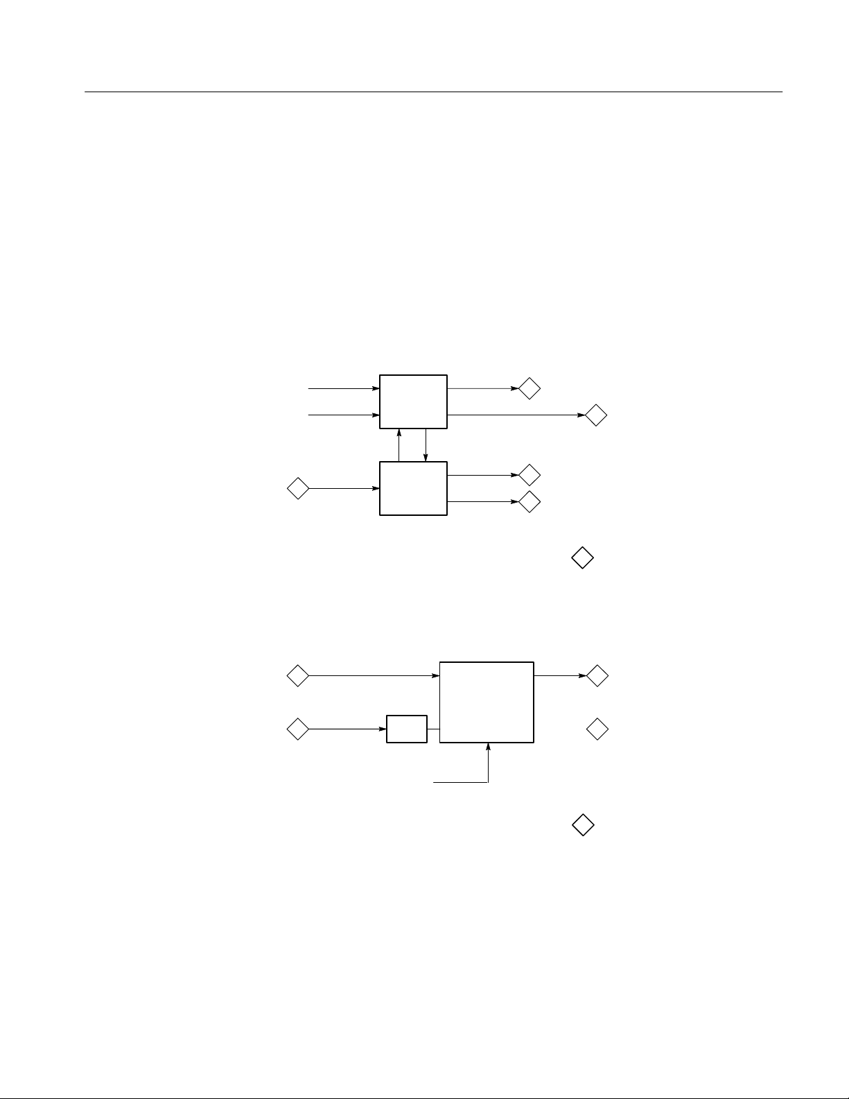
A1 Front Panel Board
A1U6 and A1U7 decode the button matrix so that the microprocessor can poll
front-panel activity using the serial interface (see Figure 3–1). A1U4 and A1U9
control the front-panel LED display. A1U8 provides A/D conversion of the
front-panel knobs. The front-panel settings for both gain and position provide
input to the vertical and horizontal amplifiers.
NOTE. The diamond numbers that appear in the figures are references to the
other block diagrams. The block diagram numbers appear at the end of the
figure caption. For example, in Figure 3–1, the diamond number 5 appears in
the block diagram. The circuitry that connects to the Front Panel board at the
point indicated by the diamond number 5 is shown in block diagram 5
(Figure 3–5 on page 3–4).
A2 Main Board
FRONT PANEL
SERIAL I/O
5
Figure 3–1: Front Panel board block diagram 1
The A2 Main Board in the WVR500 monitor provides most of the instrument’s
functionality. To simplify the description of the Main Board, its description is
broken down in major functional sections.
BUTTONS
LEDS
KNOBS
WVR500 Waveform/Vector Monitor Service Manual
3–1
Page 46
Theory of Operation
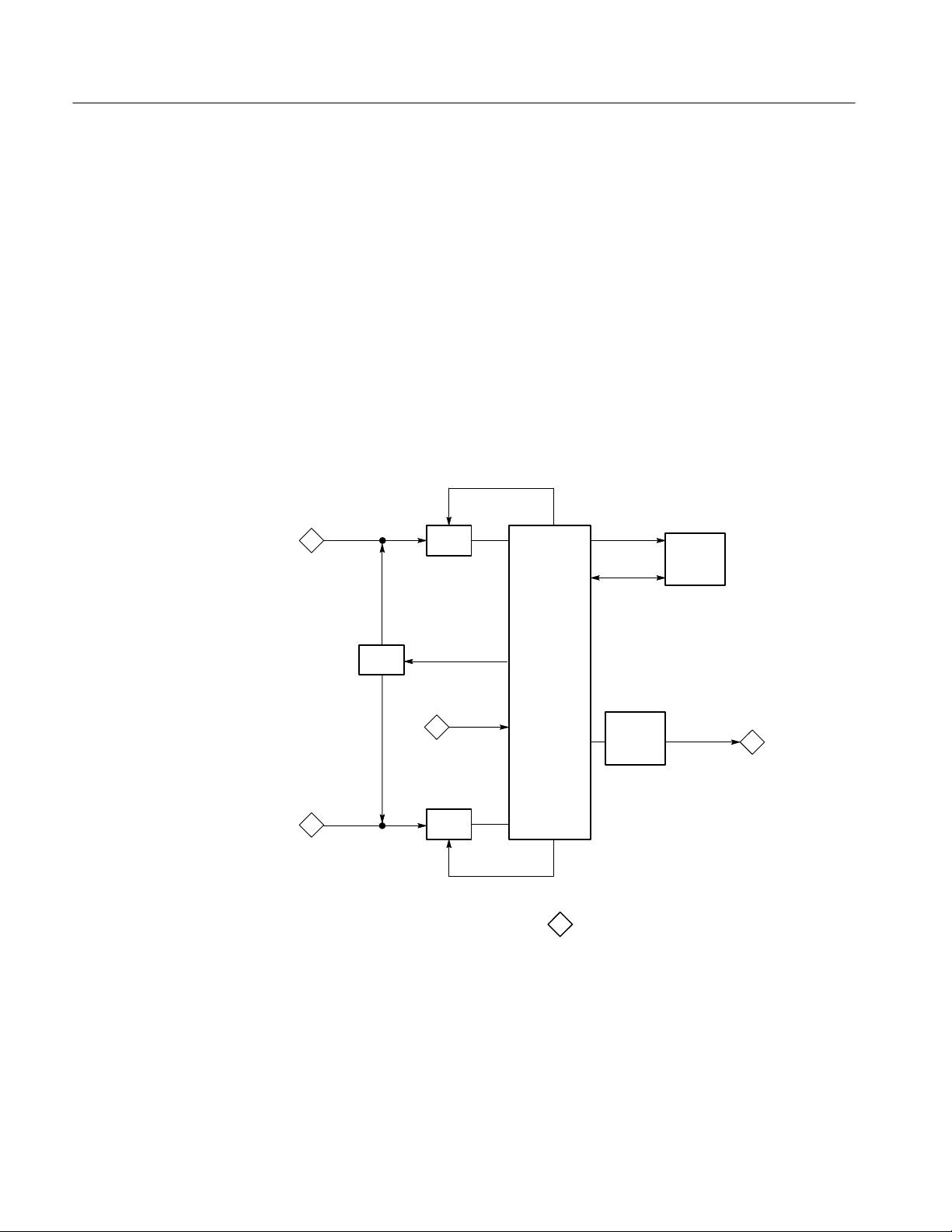
CH-A, CH-B, and
EXT REF
Entering in from the rear-panel connectors (see Figure 3–2), the CH-A and CH-B
input are AC or DC coupled, depending on the position of the jumper on A2J1.
A2U1 provides amplification buffering, with channel switching handled by
A2U117 and control signals from the microprocessor. For the EXT REF input,
A2Q9 provides the amplification buffering. A2U17 switches between internal
and external video reference using control signals from the microprocessor.
A2U18 buffers the reference signal and outputs the REF VID signal to the sync
separator and to the subcarrier sample circuitry.
CH-A
CPLG
CH-B
EXT
REF
INPUT
U117
CPLG
REFERENCE
SWITCH
INT
VIDEO
U17
4 9
CLAMP FILTER
FILTER
SELECT
3 4
REF
VIDEO
3
FILT
VIDEO VERT
GAIN
R–Y
VERT
OUT
8
3–2
SYNC
SEPARATOR
SWEEP
CONTROL/
VIDEO
REFERENCE
CONTROL
DISPLAY
SIGNALS
LTRIG
FTRIG
SWEEP
GENERATOR
Figure 3–2: Partial Main board block diagram 2
WVR500 Waveform/Vector Monitor Service Manual
SWEEP
SIG
4
B–Y
HORIZ
MAG
HORIZ
OUT
8
Page 47
Theory of Operation
Vector Demodulators
The subcarrier generator (see Figure 3–3) uses the NTSC and PAL selection
signals from the microprocessor to switch between the two oscillators, A2Y1 and
A2Y2. The subcarrier-sample circuitry uses video-control signals and commands
from the microprocessor and the REF VID signal to provide F_CNT reference
signal for the phase-lock loops. The sample circuit is made up by A2U36,
A2U32, A2U59A, A2U31, and the surrounding circuit. A2U34 generates the
ECL subcarrier signal as well as the quadrature signals for the vector demodulator. The video timing generator, A2U108, receives the ECL subcarrier and
generates the vertical and horizontal timing signals for the FPGA. The INT VID
signal is filtered, switched through A2U39A or B, and is passed through the gain
amplifier A2U45 (see Figure 3–4) before going to the vector demodulators.
ECL SUB
QUADRATURE SIGNALS
FILTER
SELECT
PAL
PLS
9
2
8
4
2
PAL
NTSC
REF VIDEO
SUBCARRIER
GENERATOR
SUBCARRIER
SAMPLE
Figure 3–3: Subcarrier generator block diagram 3
Vertical Signal Generation
The demodulators A2U41 and A2U42 use the quadrature signals and the video
signal to generate the R-Y and B-Y signals.
QUADRATURE SIGNALS
3 2
VECTOR
DEMODULATORS
2
INT VIDEO
X1/X5
GAIN
VECTORS
R–Y
B–Y
2
Figure 3–4: Vector demodulators block diagram 4
The clamp (see Figure 3–2) is activated through the front panel and is made up
primarily by A2U5 and A2U6. The clamped signal is then filtered by A2U7,
with filter switching handled by control signals to A2U3 parts A, B, and C. The
output signal, FILT VID, goes to the vertical amplifier, and the vertical amplifier
outputs either the FILT VID signal or the R-Y signal from the vectorscope
vertical demodulator.
WVR500 Waveform/Vector Monitor Service Manual
3–3
Page 48

Theory of Operation
Horizontal Signal
Generation
Microprocessor
A2U13 separates the sync from the REF VID signal (see Figure 3–2) and
generates two control signals used by the control and timing circuit. The sweep
control and timing components, along with the state machines in A2U21 and
A2U22, receive control signals from the sync separator and the microprocessor.
These signals are used to generate the display control signals and the timing
signals used by the rest of the instrument. The sweep generator is made up of
A2U20, A2Q7, and A2Q8. The sweep generator is controlled by either the line
or field trigger timing signals (LTRIG or FTRIG) coming from the state machine
A2U21. The horizontal amplifier outputs either the SWEEP SIG signal from the
sweep generator or the B-Y signal from the vectorscope horizontal demodulator.
The microprocessor, A2U72 (see Figure 3–5), receives information from three
primary sources: (1) interrupt and timing signals from the video and display
circuitry, (2) the rear panel RS-232 port, and (3) the serial interface signals, SCK,
MISO, and MOSI, on the microprocessor. A2U82 buffers signals to and from the
microprocessor. A2U71 provides a reset to the microprocessor on instrument
power-up, or can provide a manual reset by shorting the pins on A2J8.
PERIPHERAL
CHIP SELECT
ADRS
DATA
PROC
INTFC
6
7
8
SERIAL I/O
1
RESET
w PROC
INTERRUPTS
RS-232
10
ADRS
DATA
DATA
ADRS
ADRS
ROM RAM
BUFFERS
CHIP
SELECTS
ADRS
DATA
DATA
ADRS
NVRAM
Figure 3–5: Microprocessor circuitry block diagram 5
The DAC (see Figure 3–6), A2U46, uses signals from the microprocessor to
generate analog control voltages for adjustable instrument functions. These
voltage signals are buffered by parts of A2U47, A2U48, A2U49, A2U50, and
A2U59. The serial latches, A2U51, A2U52, A2U53, and A2U54, receive serial
data and control signals from the microprocessor to output mode-enabling
analog-control logic to the rest of the instrument.
3–4
WVR500 Waveform/Vector Monitor Service Manual
Page 49

Theory of Operation
ANALOG
LOGIC
CONTROL
VOLTAGES
PROC
INTFC
5
PROC
INTFC
5
DAC
SERIAL
LATCHES
ANALOG
CONTROL
Figure 3–6: Analog control circuitry block diagram 6
The serial interface (see Figure 3–5) decodes peripheral-chip selection through
A2U70. The ROMs, A2U68 and A2U69, contain the instrument control
program. A2U79, A2U80, A2U81, and A2U84 serve as data and address buffers
for the control lines. A2U77 and A2U78 decode the chip selection information
using the address and data lines from the microprocessor. The buffered data and
address lines from the microprocessor go to the RAM, A2U66 and A2U67, and
the NVRAM. The NVRAM stores the instrument calibration constants and the
state of the instrument for use on instrument power-up. The microprocessor uses
the address and data lines to control the instrument, primarily through the FPGA,
RAM DAC, and the Rasterizer.
FPGA, RAM DAC, and
Rasterizer
The FPGA (see Figure 3–7), A2U86, provides control and timing signals to the
rest of the instrument. The FPGA looks at the video signal (WFM 0-7) coming
from line memory and makes decisions based on the input and the control codes
it receives from the rest of the system. The FPGA is configured using the serial
interface during initial instrument start-up. The FPGA sends control signals and
correct video timing to the RAM DAC. The RAM DAC uses the video and
control signals to generate RGB video signals to send to the encoder.
8
WFM (0-7)
5
PROC
INTFC
FPGA
& TIMING
SIGNALS
WFM (3-7)
WFM (0-2)
RAMDACCONTROL
R, G, B
9
Figure 3–7: FPGA and RAMDAC circuitry block diagram 7
WVR500 Waveform/Vector Monitor Service Manual
3–5
Page 50
Theory of Operation
The A/D converters (see Figure 3–8), A2U89 and A2U90, are controlled by the
rasterizer, with input from the dither generators, to sample the incoming video
signal. A2U94 and A2U97 generate controlled noise which improves the
appearance of the output signal. The rasterizer, A2U88, controls the sampling of
the vertical and horizontal signals coming through the A/D converters, and the
samples are buffered into display memory to be used in generating rasterized
output one line at a time.
The rasterizer provides an analog look to the display by using the variable
persistence algorithms stored in display memory, A2U95 and A2U96. They hold
the data used by the rasterizer to generate the line output and serve as data
storage while the rasterizer completes its algorithms. A2U92 is the line memory
controlled by the rasterizer to output the video signal (WFM 0-7) one line at a
time to the FPGA and the RAM DAC.
SAMPLE
VERT
OUT
2
DITHER
5
HORIZ
OUT
2
A/D
DITH (0-1)
PROC
INTFC
A/D
Y IN
RASTERIZER
X IN
SAMPLE
Figure 3–8: Rasterizer block diagram 8
ADRS
DATA
LINE
MEMORY
DISPLAY
MEMORY
WFM (0-7)
7
3–6
WVR500 Waveform/Vector Monitor Service Manual
Page 51

Theory of Operation
Video Out Generation
The encoder (see Figure 3–9), A2U111, uses the ECL subcarrier input from the
subcarrier generator to encode the rasterized RGB signals from the RAM DAC
and to provide an encoded NTSC or PAL signal to the output clamp. The clamp,
A2U112 and A2U113, forces the level of the encoded video signal to match that
of the INT VID signal. The mux, A2U109, switches rapidly between the internal
video and the encoded video. The video is buffered by A2U110 for output to the
rear-panel connectors.
INT VIDEO
2
7
ECL SUB
3
LINE
VOLTAGE
R, G, B
ENCODER
VIDEO
TIMING
GENERATOR
POWER
SUPPLY
BOARD
+5V
+15V
–15V
CLAMP/
MUX
VIDEO
TIMING
SIGNALS
REGULATORS
OUTPUT
BUFFER
VIDEO
OUT
+12V
–12V
A3 Power Supply Board
A4 Serial Filter Board
Figure 3–9: Video out and power supply block diagram 9
The Power Supply board (see Figure 3–9) provides the ±15 V and ±5 V supplies
needed by the Main board via A2J11. The Power Supply board circuitry is
supported only by the module exchange program. The regulators A2U62 and
A2U63 use the
±15V to generate the ±12 V supplies which are used by the
analog circuitry.
The Serial Filter board (see Figure 3–10) provides filtering and noise immunity
for signals coming to and from the instrument through the RS-232 rear-panel
connector. A2U101 serves as the interface driver.
R2–232
REMOTE
FILTERS INTERFACE
RXD
TXD
5
5
Figure 3–10: Serial Filter board block diagram 10
WVR500 Waveform/Vector Monitor Service Manual
3–7
Page 52

Theory of Operation
3–8
WVR500 Waveform/Vector Monitor Service Manual
Page 53

Performance Verification
Page 54

Page 55

Performance Verification
vete
iversal
tio
stem
This section contains a short-form and long-form version of the performance
verification procedures.
Required Equipment List
The following test equipment and accessory items are required to perform the
performance verification procedures. Broad specifications are followed by an
example of equipment that meet these specifications.
T able 4–1: Verification required test equipment
Type of Equipment Requirements Example
T est Oscilloscope Vertical Amplifier:
30 MHz Bandwidth, 2 mV sensitivity.
Time Base:
10 ns/Div to 5 ms/Div sweep speeds, triggering
to 50 MHz.
Television Signal Generator Color test signals for the television standard of
the monitor to be tested: color bars signal,
linearity staircase and variable apl, pulse and
bar; with 2T pulse, 2T bar, and modulated
pulse, field square wave signal, and black burst
signal.
NOTE: The 1410–Series generators with standard SPG and TSG modules can be used, but not
all checks and adjustments can be made. The standard SPG2/SPG12 modules will not check
lock to changes in sync amplitude, cw lock to changes in burst amplitude, and frequency lock to
burst offset frequency changes.
The signal generator must be ordered with one or both options (AA and AB). The TSG3 and
TSG13 are Modulated Staircase Generators with variable APL. The TSG5 and TSG15 are Pulse
and Bar Generators with modulated pulse and field square wave signals.
Leveled Sine Wave Generator Output Level Range: –11.55 dBm (200 mV) to
0.43 dBm (800 mV).
Frequency: 50 kHz to 10 MHz.
Function Generator Range: 0.1 to 5 Vpp when loaded by 75 ;
10 Vpp when unloaded.
Frequency: 50 kHz to 10 MHz.
A TEKTRONIX TAS 465 Oscilloscope. Also
10X probe, P6109B, and 1X probe, P6119B.
NTSC TEKTRONIX 1410 with Option AA and
Option AB (modified SPG2 and TSG7), TSG3,
and TSG5.
PAL TEKTRONIX 1411 with Option AA and
Option AB (modified SPG12 and TSG17),
TSG13, and TSG15.
Wa
k 9100 Un
with Oscilloscope Calibration Module (Option 250)
Fluke 5500A Multi-product Calibrator with
Oscilloscope Calibration Option
(Option 5500A-SC)
Calibra
n Sy
Picture monitor Television picture monitor for the appropriate
video standard (NTSC or PAL)
WVR500 Waveform/Vector Monitor Service Manual
Generic television picture monitor with BNC
video input connector
4–1
Page 56

Performance Verification
T able 4–1: Verification required test equipment (cont.)
Type of Equipment ExampleRequirements
Variable Autotransformer General Radio Metered Auto Transformer
W10MT3W. If 220 V operation must be
checked, a conversion transformer or appropri-
ate 220 V autotransformer is needed.
Voltmeter Range: 0 to >100 VDC. Accuracy: ±0.1%. TEKTRONIX DMM252 Digital Multimeter.
Frequency Counter Range: 10 Hz to 10 MHz. Accuracy: ±0.001%. TEKTRONIX CMC251 Multifunction Counter.
Video Amplitude Calibrator (V AC) Signal: Adjustable square wave 0.0 to
999.9 mVpp.
Resolution: 0.1 mV .
Accuracy: 0.05%.
Frequency: Approximately 270 Hz.
Peak-to-Peak Detector Input Signal Range: 0.25 to 1.0 Vpp.
Flatness: ±0.2% 50 kHz to 10 MHz.
Input Impedance: 75 .
Spectrum Analyzer Bandwidth up to 10 MHz and sensitivity up to
50 dB; with internal tracking generator.
Power Module For powering and housing a Tektronix
067-0916-00 and a 015-0408-00.
RF Bridge Range: At least 46 dB return loss sensitivity,
50 kHz to 10 MHz (used with 75 precision
high-frequency termination).
75 Precision High-Frequency
End-Line Termination
75 Terminators Six required; two should be end-line, and four
0.25% DC accuracy, with return loss of 42 dB
or greater up to 30 MHz (for use with the RF
Bridge).
should be feedthrough type.
TEKTRONIX 067-0916-00 installed in a
TM500-Series Power Module.
Tektronix Part No. 015-0408-00 (includes
Peak-to-Peak Detector Head 015-0413-00)
installed in a TM500-Series Power Module.
Tektronix 2712 Option 04.
Tektronix TM500-Series Power Module.
Wide Band Engineering Part No. A57TLSCR.
Wide Band Engineering termination model
A56T75B.
End-line, 75 terminator
(Tektronix Part No. 011-0102-00).
Coaxial Cables Three 75 cables required, one precision
(1%) 50 cable required.
50 -to-75 Minimum Loss
Attenuator
Dual-Input Coupler Matched BNC cable-T for making phase
comparisons between two inputs. Matched
length of the two arms within ±0.1 inch.
4–2
WVR500 Waveform/Vector Monitor Service Manual
Feedthrough, 75 terminator
(Tektronix Part No. 011-0103-02).
75 – 42-inch
(Tektronix Part No. 012-0159-00).
50 – 36-inch 1% precision
(Tektronix Part No. 012-0482-00).
Tektronix Part No. 011-0057-00.
Tektronix Part No. 067-0525-02.
Page 57

Performance Verification
Short-Form Performance Verification
The short-form of the performance verification in Table 4–2 is for those who are
familiar with the long-form performance verification procedure. Page numbers
provide easy cross-reference to the long-form procedure.
T able 4–2: Short-form performance verification
Step Requirements Page
Preliminary Setup Initial equipment connections and control settings. 4–4
Power Supply Operation Stable operation over an AC input range of 90 – 250 V. 4–5
Vertical Gain 1 Volt Full Scale (X1): 1 V input displayed within 1% of 140 IRE (1.00 V
PAL) graticule. X5 Gain: 0.2 V input displayed within 5% of 140 IRE (1.00 V
PAL) graticule. Input to Output Gain Ratio: 1:1 ±5% at 15 kHz.
Input Channel Frequency Response X1 Gain Response (Flat filter selected): 50 kHz to 6 MHz within 2% of
response at 50 kHz. X5 Gain Response (Flat filter selected): 50 kHz to
6 MHz within 5% of response at 50 kHz.
Luminance Filter Frequency Response Response at 15 kHz within ±1% between Flat and Luminance filters.
≥30 dB attenuation at 4.00 MHz.
Sweep Timing and Integral Linearity Sweep Timing Accuracy: 5 ms/Div. (1 Line), 10 ms/Div. (2 Line), and
1.0 ms/Div . (2 Line + MAG), ±2%. 0.2 ms/Div. (1 Line + MAG) ±3%.
Integral Linearity: ±1%.
Horizontal Magnifier Registration and
Position Range
X5 Gain Registration X5 Gain Registration: ≤1 major division of vertical shift from baseline
Overscan, Pulse-to-Bar Ratio, and Tilt Overscan: ≤2% variation in baseline of 100 IRE (700 mV PAL) 12.5T (20T
Vertical Position Range and Variable Gain
Range
DC Restorer Response Attenuation of 60 Hz (50 Hz PAL) on Input Signal: SLOW mode: ≤20%.
Vector Gain and Phase Vector Gain Stability: ±2.5%. Vector Phase Accuracy: ±1.25°. 4–13
Vector Phase Stability Phase Shift with Input Channel Change: ±0.5°. Phase Shift with V ariable
Internal Synchronization Stable display with composite video or black burst with sync amplitude of
Magnifier Registration: Magnification occurs about the center of the screen.
Position Range: Any portion of the sweep can be positioned on screen.
between unmagnified and magnified signal.
PAL) modulated pulse as it is positioned over the middle 80% of the screen.
Pulse-to-Bar Ratio: X1: 0.99:1 to 1.01:1; X5: 0.98:1 to 1.02:1. Tilt: ≤1%.
Vertical Position Range: 1 V signal can be positioned so that peak white and
sync tip can be placed at blanking level, with the DC Restorer Clamp on,
regardless of gain setting. Variable Gain Range: Input signals between 0.8 V
and 2 V can be adjusted to 140 IRE (1.0 V) display. 160 mV and 400 mV for
X5 Gain.
FAST mode: ≥90%. Blanking Level Shift with 10% to 90% APL Change:
APL changes from 50% to either 10% or 90% will cause blanking level shift
of ≤1 IRE (7.14 mV PAL). Blanking Level Shift Due to Presence or Absence
of Burst: ≤1 IRE unit (7.14 mV PAL) shift.
Gain Control Varied from +3 dB to –6 dB: ±1°. Phase Shift with Burst
Amplitude Change from Nominal to ±6 dB: ±2°. Phase Shift with Subcarrier
Frequency Change from F
40 IRE (300 mV PAL) ±6 dB.
to FSC ±50 Hz (FSC ±10 Hz PAL): ±2°.
SC
4–5
4–6
4–7
4–8
4–9
4–9
4–10
4–1 1
4–12
4–14
4–15
WVR500 Waveform/Vector Monitor Service Manual
4–3
Page 58

Performance Verification
T able 4–2: Short-form performance verification (cont.)
Step PageRequirements
Chrominance Bandwidth Chrominance Bandwidth: Upper –3 dB Point: FSC + 500 kHz, ±100 kHz.
Lower –3 dB Point: F
Return Loss Video Inputs: ≥40 dB from 50 kHz to 6 MHz. Power on or off. Video
Outputs: ≥30 dB from 50 kHz to 6 MHz. Power on.
– 500 kHz, ±100 kHz.
SC
Long-Form Performance Verification
Perform the following procedure to verify the operation of the instrument.
Preliminary Setup
Perform the following procedure to start the performance verification:
1. Connect the WVR500 monitor AC power cord to the variable autotransform-
er. Set the mains Power switch for the autotransformer to On and set the
autotransformer to the local nominal mains voltage (110 V or 220 V).
2. Connect a 75 W cable from one of the WVR500 monitor VIDEO OUT
connectors to the picture monitor input via a 75 W in-line terminator.
3. Connect the output of the VAC to the CH-A input on the WVR500 monitor.
Do not terminate the CH-A loop-though. Set the VAC for a 999.9 mV
output.
4–16
4–17
4. Set the WVR500 monitor front-panel controls to WAVEFORM display,
CHA input, 2LINE sweep, FLAT filter, and INT reference. Turn off MAG,
GAINX5, and the LINE SEL mode.
5. Adjust the GP Knob to set the signal intensity to the desired level.
6. Enter the Configure menu. Select NTSC STANDARD, CLAMP ON,
SLOW CLAMP, PAL PLUS V OFF, NTSC ALT V OFF, GRATICULE ON,
SETUP, SYNC MESSAGE ON, WIDE SCREEN OFF, and 75% BARS.
7. Enter the Operating menu (MENU button) and select ALARM OFF,
READOUT ON, MENU RIGHT, and VAR GAIN OFF.
8. Enter the Display menu. Select GRAT INTENS and adjust the GP Knob to
set the graticule intensity to the desired level.
9. Press the CLEAR button to clear the menu display.
NOTE. Once the instrument is powered up, allow at least 20 minutes of warm-up
time before continuing.
4–4
WVR500 Waveform/Vector Monitor Service Manual
Page 59

Performance Verification
Power Supply Operation
Vertical Gain
Requirement: Stable operation over an AC input range of 90 – 250 V.
1. Vary the autotransformer from low-line to high-line voltage (90 – 132 V for
110 V, or 180 – 250 V for 220 V operation).
2. Check for stable instrument operation over the prescribed voltage range.
3. Set the autotransformer to the nominal mains voltage.
Requirement: 1 Volt Full Scale (X1): 1 V input displayed within 1% of 140 IRE
(1.00 V PAL) graticule. X5 Gain: 0.2 V input displayed within 5% of 140 IRE
(1.00 V PAL) graticule. Input to Output Gain Ratio: 1:1 ±5% at 15 kHz.
1. Check for display amplitude of 140 IRE ±1% (1.4 IRE).
2. Set the VAC for a 199.9 mV output.
3. Turn on GAIN X5 (front panel).
4. Check for display amplitude of 140 IRE ±5% (7 IRE).
5. Enter the Configure menu and select PAL STANDARD. Clear the menu
display.
6. Check for display amplitude of 1000 mV ±5% (50 mV).
7. Turn off GAINX5 (front panel).
8. Set the VAC for a 999.9 mV output.
9. Check for display amplitude of 1000 mV ±1% (10 mV).
10. Remove the VAC signal from the CH-A input.
11. Connect a 75 W cable from the output of the function generator to the
oscilloscope input. Set the oscilloscope for 200 mV/Div.
12. Set the function generator frequency for a 15 kHz sine wave and adjust the
generator amplitude for exactly 1.0 V of display.
13. Move the output of the function generator from the oscilloscope to the
WVR500 monitor CH-A input. Do not terminate the CH-A loopthrough.
14. Connect a cable from the second VIDEO OUT connector to the oscilloscope
input with a 75 W feedthrough terminator.
15. Connect a black burst signal from the television signal generator to the
EXT REF input using a 75 W cable. Terminate the loopthrough in 75 W.
16. Select EXT REF and PICTURE display mode.
17. Check for a 1 V display on the oscilloscope ±5% (50 mV).
WVR500 Waveform/Vector Monitor Service Manual
4–5
Page 60

Performance Verification
18. Remove the cable from the second VIDEO OUT connector, then select
Waveform display mode.
19. Remove the function generator signal from the CH-A input.
20. Remove the black burst signal and terminator from the EXT REF input.
Input Channel Frequency
Response
Requirement: X1 Gain Response (Flat filter selected): 50 kHz to 6 MHz within
2% of response at 50 kHz. X5 Gain Response (Flat filter selected): 50 kHz to
6 MHz within 5% of response at 50 kHz.
1. Select EXT reference (front panel).
2. Connect the output of the leveled sine wave generator to the CH-A input,
using the 50 W precision cable and 50 W-to-75 W minimum loss attenuator.
3. Connect the 015-0413-00 Peak-to-Peak Detector Head to the open CH-A
loopthrough and connect the other end to the 015-0408-00 Peak-to-Peak
Detector + Input.
4. Connect the Peak-to-Peak Detector Output to either an oscilloscope or
DMM. Note: The DMM must have a “Reading Null” ability, or else use the
oscilloscope.
5. Set the leveled sine wave generator frequency to 50 kHz and adjust the
generator amplitude for exactly 700 mV (100 IRE NTSC) of display.
6. Adjust the Peak-to-Peak Detector plus amplifier and input control until the
Green LED is on.
7. Note the DMM readout level or the oscilloscope DC level.
4–6
8. Set the sine wave generator frequency to 4.43 MHz (3.58 MHz NTSC).
9. Adjust the sine wave generator amplitude for exactly 700 mV (100 IRE
NTSC) of display.
10. Check that the DMM readout level, or the oscilloscope DC level, is within
±14 mV of the reading noted in step 7.
11. Set the sine wave generator frequency to 6 MHz.
12. Adjust the sine wave generator amplitude for exactly 700 mV (100 IRE
NTSC) of display.
13. Check that the DMM readout level, or the oscilloscope DC level, is within
±14 mV of the reading noted in step 7.
14. Enter the Configure menu and select NTSC STANDARD.
15. Repeat steps 5 through 13 using the NTSC values.
WVR500 Waveform/Vector Monitor Service Manual
Page 61

Performance Verification
16. Move the sine wave generator cable and the Peak-to-Peak Detector Head
from the CH-A input to the CH-B input.
17. Select CHB input (front panel). Enter the Configure menu and select PAL
STANDARD.
18. Repeat steps 5 through 15 for the CH-B input.
19. Remove the sine wave generator cable and the Peak-to-Peak Detector Head
from the CH-B INPUT.
20. Connect the sine wave generator cable to a dual-input coupler via a 75 W
in-line terminator.
21. Connect the dual-input coupler to the CH-A and CH-B inputs.
22. Set the sine wave generator frequency to 50 kHz.
23. Select CHB input, and turn on GAINX5.
24. Adjust the sine wave generator amplitude for exactly 100 IRE (700 mV
PAL) of display.
Luminance Filter
Frequency Response
25. Set the sine wave generator frequency to 3.58 MHz (4.43 MHz PAL).
26. Check that the display amplitude is 100 IRE (700 mV PAL) ±5%.
27. Set the sine wave generator frequency to 6 MHz.
28. Check that the display amplitude is 100 IRE (700 mV PAL) ±5%.
29. Enter the Configure menu and select PAL STANDARD.
30. Repeat steps 22 through 28 using the PAL values.
31. Select CHA input (front panel). Enter the Configure menu and select NTSC
STANDARD.
32. Repeat steps 22 through 30 for the CH-A input.
33. Turn off GAINX5.
Requirement: Response at 15 kHz within ±1% between Flat and Luminance
filters. ≥30 dB attenuation at 4.00 MHz.
1. Replace the sine wave generator signal on the dual-input coupler with the
output from the function generator.
2. Set the function generator for a 15 kHz sine wave, and then adjust the
generator for a display amplitude of 100 IRE.
WVR500 Waveform/Vector Monitor Service Manual
4–7
Page 62

Performance Verification
3. When switching between FLAT and LUM filters, check that the display
amplitude changes <1 IRE.
4. Select FLAT filter and INT reference.
5. Replace the function generator signal on the dual-input coupler with the
output from the leveled sine wave generator.
6. Set the sine wave generator frequency to 50 kHz, and then adjust the
generator for a display amplitude of 100 IRE.
7. Select LUM filter and turn on GAINX5.
8. Set the sine wave generator frequency to 4.00 MHz.
9. Check for display amplitude of <5 IRE (0.5 major division).
10. Select FLAT filter, and turn off GAINX5.
Sweep Timing and
Integral Linearity
Requirement: Sweep Timing Accuracy: 5 ms/Div. (1 Line), 10 ms/Div. (2 Line),
and 1.0 ms/Div. (2 Line + MAG), ±2%. 0.2 ms/Div. (1 Line + MAG) ±3%.
Integral Linearity: ±1%.
1. Set the sine wave generator frequency to 100 kHz.
2. Check for 1 cycle per division, ±1 minor division, over the center 10 grati-
cule divisions, with each cycle being within ±1 minor division of a major
graticule mark.
3. Set the sine wave generator frequency to 1 MHz.
4. Turn on MAG (front panel).
5. Check for 1 cycle per division, ±1 minor division, over the center 10 grati-
cule divisions.
6. Check for 1 cycle per division over both ends of the sweep, ±1 minor
division, using the horizontal position control and ignoring the first and
last cycle.
7. Set the sine wave generator frequency to 2 MHz.
8. Select 1LINE sweep (front panel).
9. Check for 1 cycle per division, ±1.5 minor divisions, over the center
10 graticule divisions.
4–8
10. Check for 1 cycle per division over both ends of the sweep, ±1.5 minor
division, using the horizontal position control and ignoring the first and
last cycle.
11. Set the sine wave generator frequency to 200 kHz.
WVR500 Waveform/Vector Monitor Service Manual
Page 63

Performance Verification
12. Turn off MAG (front panel).
13. Check for 1 cycle per division, ±1 minor division, over the center 10 grati-
cule divisions.
14. Enter the Configure menu and select PAL STANDARD. Clear the menu
display.
15. Repeat steps 1 through 13 for PAL.
16. Remove the dual-input coupler from the CH-A and CH-B inputs.
Horizontal Magnifier
Registration and Position
Range
Requirement: Magnifier Registration: Magnification occurs about the center of
the screen. Position Range: Any portion of the sweep can be positioned on
screen.
1. Connect a 75 W cable from the NTSC television signal generator to the
CH-A input. Terminate the loopthrough in 75 W.
2. Set the television signal generator for an NTSC color bars output.
3. Enter the Configure menu and select NTSC STANDARD. Clear the menu
display.
4. Select 2LINE sweep. Horizontally center the signal display, then turn on
MAG.
5. Check that some portion of the vertical interval is displayed.
6. Check by adjusting the horizontal position control, that the magnified
display can be positioned off the screen to the left and to the right.
7. Turn off MAG.
8. Check by adjusting the horizontal position control that the display cannot be
positioned off the screen to the left or to the right.
9. Replace the NTSC color bars signal on the CH-A input with a PAL color
bars signal.
10. Enter the Configure menu and select PAL STANDARD. Clear the menu
display.
11. Repeat steps 4 through 8 for PAL.
X5 Gain Registration
WVR500 Waveform/Vector Monitor Service Manual
Requirement: X5 Gain Registration: ≤1 major division of vertical shift from
baseline between unmagnified and magnified signal.
1. Enter the Configure menu. Select CLAMP ON and CLAMP SLOW, and
then clear the menu.
4–9
Page 64

Performance Verification
2. Position the signal baseline to the graticule baseline, and then turn on
GAINX5.
3. Check that the signal is on the graticule baseline ±1 major division.
4. Turn off GAINX5.
5. Replace the PAL color bars signal on the CH-A input with an NTSC color
bars signal.
6. Enter the Configure menu and select NTSC STANDARD. Clear the menu
display.
7. Repeat steps 2 through 4 for NTSC.
Overscan, Pulse-to-Bar
Ratio, and Tilt
Requirement: Overscan: ≤2% variation in baseline of 100 IRE (700 mV PAL)
12.5T (20T PAL) modulated pulse as it is positioned over the middle 80% of the
screen. Pulse-to-Bar Ratio: X1: 0.99:1 to 1.01:1; X5: 0.98:1 to 1.02:1. Tilt: ≤1%.
1. Set the television signal generator output for the pulse-and-bars signal.
2. Select 2LINE sweep and turn on MAG (front panel).
3. Check that the pulse amplitude is within 1 IRE (7 mV PAL) of the bar
amplitude.
4. Turn on GAIN X5 and position the signal to the graticule baseline.
5. Check that the pulse amplitude is within 1 major division (0.75 major
division PAL) of the bar amplitude.
6. Turn off MAG.
7. Check that the bottom edge of the mod pulse varies <1 major division
(0.75 major division PAL), while positioning the signal vertically over the
entire graticule area.
8. Select 2FLD sweep.
9. Check for <0.5 major division of tilt on the bar.
4–10
10. Turn on the field square wave on the pulse-and-bar generator.
11. Check for <0.5 major division of tilt on the bar.
12. Turn off GAINX5.
13. Turn off the field square wave on the pulse-and-bar generator.
14. Replace the NTSC pulse-and-bar signal on the CH-A input with a PAL
pulse-and-bar signal. Leave the loopthrough terminated.
WVR500 Waveform/Vector Monitor Service Manual
Page 65

Performance Verification
15. Enter the Configure menu, select PAL STANDARD, then clear the menu
display.
16. Repeat steps 2 through 13 for PAL.
Vertical Position Range
and Variable Gain Range
Requirement: Vertical Position Range: 1 V signal can be positioned so that peak
white and sync tip can be placed at blanking level, with the DC Restorer Clamp
on, regardless of gain setting. Variable Gain Range: Input signals between 0.8 V
and 2 V can be adjusted to 140 IRE (1.0 V) display. 160 mV and 400 mV for X5
Gain.
1. Select 2LINE sweep.
2. Replace the PAL pulse-and-bar signal on the CH-A input with the PAL color
bars signal. Leave the loopthrough terminated.
3. Check that by adjusting the vertical position control, the white bar and sync
tip portions of the signal can be adjusted to the graticule baseline.
4. Replace the PAL color bars signal on the CH-A input with the output of the
leveled sine wave generator. Leave the loopthrough terminated.
5. Enter the Configure menu, select NTSC STANDARD. Clear the menu
display.
6. Set the leveled sine wave generator frequency to 3.58 MHz, then adjust the
generator amplitude control for a display of 114 IRE.
7. Enter the Operating menu (MENU button) and select VAR GAIN ON. Clear
the menu display.
8. Check that by adjusting the GP Knob the signal amplitude can be adjusted to
140 IRE.
9. Enter the Operating menu (MENU button) and select VAR GAIN OFF. Clear
the menu display.
10. Adjust the leveled sine wave generator amplitude control for a display of
140 IRE.
11. Enter the Operating menu (MENU button) and select VAR GAIN ON. Clear
the menu display.
12. Check that by adjusting the GP Knob the signal amplitude can be adjusted to
70 IRE.
13. Enter the Operating menu (MENU button) and select VAR GAIN OFF. Clear
the menu display.
WVR500 Waveform/Vector Monitor Service Manual
4–11
Page 66

Performance Verification
DC Restorer Response
Requirement: Attenuation of 60 Hz (50 Hz PAL) on Input Signal: SLOW mode:
≤20%. FAST mode: ≥90%. Blanking Level Shift with 10% to 90% APL Change:
APL changes from 50% to either 10% or 90% will cause blanking level shift of
≤1 IRE (7.14 mV PAL). Blanking Level Shift Due to Presence or Absence of
Burst: ≤1 IRE unit (7.14 mV PAL) shift.
1. Enter the Configure menu, select PAL STANDARD, and then clear the menu
display.
2. Connect a PAL black burst signal from the television signal generator to the
EXT REF input. Terminate the loopthrough in 75 W.
3. Replace the sine wave generator signal on the CH-A input with the output of
the function generator. Leave the loopthrough terminated.
4. Set the function generator for a 50 Hz sine wave, and set the amplitude for a
350 mV display.
5. Select EXT reference.
6. Check that the display amplitude is >280 mV.
7. Enter the Configure menu and select FAST CLAMP. Clear the menu display.
8. Check that the display amplitude is <35 mV.
9. Replace the function generator signal on the CH-A input with the PAL
linearity signal. Leave the loopthrough terminated.
10. Select INT reference and turn on GAINX5.
11. Position the signal baseline to the graticule baseline.
12. Turn on the AC bounce on the linearity signal generator.
13. Check that the signal baseline shifts <7 mV (1/3 major division).
14. Turn off the AC bounce, then replace the linearity signal on the CH-A input
with the PAL pulse and bar signal. Leave the loopthrough terminated.
15. Turn off the color burst on the pulse and bar signal generator.
16. Check that the signal baseline shifts <7.14 mV when switching the color
burst on and off.
17. Turn on the color burst on pulse and bar signal generator.
18. Turn off GAINX5, and then remove all signals and terminators from the
WVR500 monitor.
4–12
WVR500 Waveform/Vector Monitor Service Manual
Page 67

Performance Verification
Vector Gain and Phase
Requirement: Vector Gain Stability: ±2.5%. Vector Phase Accuracy: ±1.25°.
1. Connect the PAL 75% color bars signal to the CH-A and CH-B inputs using
a 75 W feedthrough terminator and dual-input coupler.
2. Select VECTOR display mode.
3. Check that all of the color vector dots can be positioned in the vector target
boxes within ±1.25° and within ±2.5% amplitude using the GP Knob for
PHASE control. The position of the burst vector is not critical.
4. Set the color bars signal generator for 100% color bars.
5. Enter the Configure menu and select 100% BARS. Clear the menu display.
6. Check that all of the color vector dots can be positioned in the vector target
boxes within ±1.25° and within ±2.5% amplitude using the GP Knob for
PHASE control. NOTE: The position of the burst vector is not critical.
7. Replace the PAL color bars signal on the CH-A and CH-B inputs with an
NTSC 100% color bars signal. Leave the inputs feedthrough terminated.
8. Enter the Configure menu and select NTSC STANDARD. Clear the menu
display.
9. Check that all of the color vector dots can be positioned in the vector target
boxes within ±1.25° and within ±2.5% amplitude using the GP Knob for
PHASE control. The position of the burst vector is not critical.
10. Select 0% setup on the television signal generator.
11. Enter the Configure menu and select NO SETUP. Clear the menu display.
12. Check that all of the color vector dots can be positioned in the vector target
boxes within ±1.25° and within ±2.5% amplitude using the GP Knob for
PHASE control. The position of the burst vector is not critical.
13. Set the color bars signal generator for 75% color bars.
14. Enter the Configure menu and select 75% BARS. Clear the menu display.
15. Check that all of the color vector dots can be positioned in the vector target
boxes within ±1.25° and within ±2.5% amplitude using the GP Knob for
PHASE control. The position of the burst vector is not critical.
16. Select 7.5% setup on the television signal generator.
17. Enter the Configure menu and select SETUP. Clear the menu display.
18. Check that all of the color vector dots can be positioned in the vector target
boxes within ±1.25° and within ±2.5% amplitude using the GP Knob for
PHASE control. The position of the burst vector is not critical.
WVR500 Waveform/Vector Monitor Service Manual
4–13
Page 68

Performance Verification
Vector Phase Stability
Requirement: Phase Shift with Input Channel Change: ±0.5°. Phase Shift with
Variable Gain Control Varied from +3 dB to –6 dB: ±1°. Phase Shift with Burst
Amplitude Change from Nominal to ±6 dB: ±2°. Phase Shift with Subcarrier
Frequency Change from F
to FSC ±50 Hz (FSC ±10 Hz PAL): ±2°.
SC
1. Connect the black burst output from the NTSC television signal generator to
the EXT REF input. Terminate the loopthrough in 75 W.
2. Select EXT reference.
3. Position the Red vector to the 0° graticule using the GP Knob (PHASE
control).
4. Check by switching between CH-A and CH-B inputs that the vector phase
changes less than ±0.5°.
5. Replace the NTSC color bars signal on the CH-A and CH-B inputs and the
black burst signal on the EXT REF input with the PAL 75% color bars and
black burst signals. Leave the loopthroughs terminated.
6. Enter the Configure menu and select PAL STANDARD. Clear the menu
display.
7. Position the Red vector to the 0° graticule using the GP Knob (PHASE
control).
8. Check by switching between CH-A and CH-B inputs that the vector phase
changes less than ±0.5°.
9. Remove all signals and terminators from the WVR500 monitor.
10. Connect the PAL black burst signal to the CH-A input. Terminate the
loopthrough in 75 W.
11. Select INT reference and CH-A input.
12. NTSC only: Enter the Configure menu and select NO SETUP. Clear the
menu display.
13. Position the burst vector to the 0° graticule using the GP Knob (PHASE
control).
14. Enter the Operating menu (MENU button) and select VAR GAIN ON. Press
the CLEAR button once.
15. Check that the vector phase changes less than ±1° while varying the vector
burst amplitude from 1/2 to 1.5 times nominal amplitude, using the GP Knob
(VECT GAIN control).
16. Enter the Operating menu (MENU button) and select VAR GAIN OFF. Clear
the menu display.
4–14
WVR500 Waveform/Vector Monitor Service Manual
Page 69

Performance Verification
17. NTSC only: Enter the Configure menu and select SETUP. Clear the menu
display.
18. Position the burst vector to the 0° graticule using the GP Knob (PHASE
control).
19. Check that the vector phase changes less than ±2° while varying the signal
burst amplitude from nominal to ±6 dB, using the television signal generator
burst amplitude control.
20. Return the burst amplitude to nominal on the television signal generator.
21. Check that the vector phase changes less than ±2° while varying the
subcarrier frequency from F
to FSC ±50 Hz (FSC ±10 Hz PAL), using the
SC
television signal generator subcarrier frequency control.
22. Replace the PAL black burst signal on the CH-A input with the NTSC black
burst signal. Leave the loopthrough terminated.
23. Enter the Configure menu and select NTSC STANDARD. Clear the menu
display.
Internal Synchronization
24. Repeat steps 12 through 21 for NTSC.
Requirement: Stable display with composite video or black burst with sync
amplitude of 40 IRE (300 mV PAL) ±6 dB.
1. Move the terminator from the CH-A input to the EXT REF input. Connect a
cable from the remaining CH-A input to the remaining EXT REF input.
2. Enter the Operating menu (MENU button) and select VAR GAIN ON. Press
the CLEAR button once.
3. Adjust the GP Knob (VECT GAIN control) to place the tip of the burst
vector on the compass rose.
4. Remove the terminator from the EXT REF input.
5. Check for a stable display in both INT and EXT reference.
6. Triple terminate the EXT REF input.
7. Check for a stable display in both INT and EXT reference.
8. Enter the Operating menu (MENU button) and select VAR GAIN OFF. Press
the CLEAR button once.
9. Remove the input signals and terminators from the WVR500 monitor.
WVR500 Waveform/Vector Monitor Service Manual
4–15
Page 70

Performance Verification
Chrominance Bandwidth
Requirement: Chrominance Bandwidth: Upper –3 dB Point: F
±100 kHz. Lower –3 dB Point: F
– 500 kHz, ±100 kHz.
SC
+ 500 kHz,
SC
1. Connect the precision 50 W cable to the output of the leveled sine wave
generator. Connect the other end of the cable to the 50 W to 75 W minimumloss attenuator, and then connect the attenuator to the CH-A input. Terminate
the loopthrough in 75 W.
2. Connect the NTSC black burst signal to the EXT REF input. Terminate the
loopthrough in 75 W.
3. Select VECTOR display mode, CH-A input, and EXT reference.
4. Set the leveled sine wave generator frequency to 3.58 MHz (4.43 MHz PAL)
and adjust the amplitude control so that the circle overlays the graticule
compass rose.
5. Decrease the frequency on the leveled sine wave generator until the edge of
the circle display reaches the –3 dB (70%) gaps on the vertical graticule axis.
See Figure 4–1.
–3 dB points Compass rose
4–16
Figure 4–1: –3 dB marks on the vector graticule
6. Check that the frequency readout on the leveled sine wave generator is
between 2.98 and 3.18 MHz (3.83 and 4.03 MHz PAL).
7. Adjust the frequency on the leveled sine wave generator until the edge of the
circle display reaches the –3 dB (70%) point gaps on the horizontal graticule
axis.
8. Check that the frequency readout on the leveled sine wave generator is
between 2.98 and 3.18 MHz (3.83 and 4.03 MHz PAL).
WVR500 Waveform/Vector Monitor Service Manual
Page 71

Performance Verification
9. Increase the frequency on the leveled sine wave generator until the edge of
the circle display expands out to the compass rose and again reduces to the
–3 dB (70%) point gaps on the vertical graticule axis.
10. Check that the frequency readout on the leveled sine wave generator is
between 3.98 and 4.18 MHz (4.83 and 5.03 MHz PAL).
11. Adjust the frequency on the leveled sine wave generator until the edge of the
circle display reaches the –3 dB (70%) point gaps on the horizontal graticule
axis.
12. Check that the frequency readout on the leveled sine wave generator is
between 3.98 and 4.18 MHz (4.83 and 5.03 MHz PAL).
13. Replace the NTSC black burst signal on the EXT REF input with the PAL
black burst signal. Leave the loopthrough terminated.
14. Enter the Configure menu and select PAL STANDARD. Clear the menu
display.
15. Repeat steps 4 through 12 for PAL.
Return Loss
16. Remove all signals and terminators from the WVR500 monitor.
Requirement: Video Inputs: ≥40 dB from 50 kHz to 6 MHz. Power on or off.
Video Outputs: ≥30 dB from 50 kHz to 6 MHz. Power on.
NOTE. The Return Loss check needs to be done only if repairs have been made
on the Input circuitry.
1. Connect a precision 50 W cable from the spectrum analyzer RF Input to the
RF Output on the RF Bridge.
2. Connect a precision 50 W cable from the spectrum analyzer TG Output to the
RF Input on the RF Bridge.
3. Select Demod/TG on the spectrum analyzer. Turn on the tracking generator
and set the tracking generator fixed level to 0.00 dBm.
4. Set the spectrum analyzer Span/Div to 1 MHz and the Resolution Bandwidth
to 30 kHz.
5. Set the spectrum analyzer Reference Level to the first major division down
from the top on the analyzer display.
6. Set the spectrum analyzer Vertical Scale to 10 dB.
7. Remove one of the cables from the RF Bridge.
WVR500 Waveform/Vector Monitor Service Manual
4–17
Page 72

Performance Verification
8. Set the spectrum analyzer Frequency to 5 MHz, turn on the Marker, and then
set the Marker to 6 MHz.
9. Reconnect the cable to the RF Bridge.
10. Note the Reference Level Readout.
11. Adjust the spectrum analyzer External Attenuation Amplitude (on the 2712
Input menu) by the amount noted in the previous step. Note: The Reference
Level Readout should now be 0.00 dBm.
12. Connect the precision high-frequency terminator to the Device Under Test
connector on the RF Bridge.
13. Check that the frequency response from 0 MHz to 6 MHz is ≥40 dBm.
14. Return the spectrum analyzer frequency marker to 6 MHz if it was moved.
15. Remove the precision high-frequency terminator from the RF Bridge.
16. Connect the Device Under Test connector on the RF Bridge to the WVR500
monitor CH-A input. Terminate the CH-A loopthrough with the precision
high-frequency terminator used in step 12.
17. Select CH-A input.
18. Check that the Reference Level Readout on the spectrum analyzer is
≥40 dBm.
19. Remove the power cord from the WVR500 monitor.
20. Check that the Reference Level Readout on the spectrum analyzer is
≥40 dBm.
21. Plug the power cord back into the WVR500 monitor.
22. Repeat steps 16 through 21 for the CH-B and EXT REF inputs.
23. Connect the Device Under Test connector on the RF Bridge to the WVR500
monitor VIDEO OUT connector.
24. Connect a PAL black burst signal to the EXT REF input. Terminate the
loopthrough in 75 W.
25. Select EXT reference and PICTURE display mode on the WVR500 monitor.
26. Check that the Reference Level Readout on the spectrum analyzer is
≥30 dBm.
27. Remove all signal cables and terminators from the WVR500 monitor.
4–18
This completes the performance verification procedures.
WVR500 Waveform/Vector Monitor Service Manual
Page 73

Adjustment Procedures
Page 74

Page 75

Adjustment Procedures
vete
iversal
tio
stem
This section contains a short-form and long-form version of the adjustment
procedures.
Required Equipment List
The following equipment and accessory items are required to perform the
adjustment procedures. Broad specifications are followed by an example of
equipment that meet these specifications.
T able 5–1: Adjustment required test equipment
Type of Equipment Minimum Requirements Examples
Oscilloscope Vertical Amplifier:
30 MHz Bandwidth, 2 mV sensitivity.
Time Base:
10 ns/Div to 5 ms/Div sweep speeds, triggering
to 50 MHz.
Television Signal Generator Color test signals for the television standard of
the monitor to be tested: color bar signal,
linearity staircase and variable apl, pulse and
bar; with 2T pulse, 2T bar, and modulated
pulse, field square wave signal, and black burst
signal.
NOTE: The 1410–Series generators with standard SPG and TSG modules can be used, but not
all checks and adjustments can be made. The standard SPG2/SPG12 modules will not check
lock to changes in sync amplitude, cw lock to changes in burst amplitude, and frequency lock to
burst offset frequency changes.
The signal generator must be ordered with one or both options (AA and AB). The TSG3 and
TSG13 are Modulated Staircase Generators with variable APL. The TSG5 and TSG15 are Pulse
and Bar Generators with modulated pulse and field square wave signals.
Leveled Sine Wave Generator Output Level Range: –11.55 dBm (200 mV) to
0.43 dBm (800 mV).
Frequency: 50 kHz to 10 MHz.
Function Generator Range: 0.1 to 5 Vpp when loaded by 75 ;
10 Vpp when unloaded.
Frequency: 50 kHz to 10 MHz.
A TEKTRONIX TAS 465 Oscilloscope. Also
10X probe, P6109B, and 1X probe, P6119B.
NTSC TEKTRONIX 1410 with Option AA and
Option AB (modified SPG2 and TSG7), TSG3,
and TSG5.
PAL TEKTRONIX 1411 with Option AA and
Option AB (modified SPG12 and TSG17),
TSG13, and TSG15.
Wa
k 9100 Un
with Oscilloscope Calibration Module
(Option 250)
Fluke 5500A Multi-product Calibrator with
Oscilloscope Calibration Option
(Option 5500A-SC)
Calibra
n Sy
Picture monitor Television picture monitor for the appropriate
video standard (NTSC or PAL)
Voltmeter Range: 0 to >100 VDC. Accuracy: ±0.1%. TEKTRONIX DMM252 Digital Multimeter.
Frequency Counter Range: 10 Hz to 10 MHz. Accuracy: ±0.001%. TEKTRONIX CMC251 Multifunction Counter.
WVR500 Waveform/Vector Monitor Service Manual
Generic television picture monitor with BNC
video input connector
5–1
Page 76

Adjustment Procedures
T able 5–1: Adjustment required test equipment (cont.)
Type of Equipment ExamplesMinimum Requirements
Video Amplitude Calibrator (V AC) Signal: Adjustable square wave 0.0 to
999.9 mVpp.
Resolution: 0.1 mV .
Accuracy: 0.05%.
Frequency: Approximately 270 Hz.
Peak-to-Peak Detector Input Signal Range: 0.25 to 1.0 Vpp.
Flatness: 0.2% 50 kHz to 10 MHz.
Input Impedance: 75 .
Power Module For powering and housing a Tektronix
067-0916-00 and a 015-0408-00.
75 Terminators Six required; two should be end-line, and four
should be feedthrough type.
Coaxial Cables Three 75 cables required, one precision
(1%) 50 cable required.
BNC-Female-to-Dual-Banana
Adapter
TEKTRONIX 067-0916-00 installed in a
TM500–Series Power Module.
Tektronix Part No. 015-0408-00 (includes
Peak-to-Peak Detector Head 015-0413-00)
installed in a TM500-Series Power Module.
Tektronix TM500-Series Power Module.
End-line, 75 terminator
(Tektronix Part No. 011-0102-00).
Feedthrough, 75 terminator
(Tektronix Part No. 011-0103-02).
75 – 42-inch
(Tektronix Part No. 012-0159-00).
75 – 24-inch
(Tektronix Part No. 012-1339-00).
50 – 36-inch 1% precision
(Tektronix Part No. 012-0482-00).
Tektronix Part No. 103-0090-00.
5–2
WVR500 Waveform/Vector Monitor Service Manual
Page 77

Short-Form Adjustment Procedures
The short-form reference table is intended for those who are familiar with the
complete adjustment procedures. Step and page numbers provide easy cross-reference to the long-form procedure on the following pages.
T able 5–2: Short-form adjustment procedures
Step Name Page #
Preliminary Setup 5–4
Check Power Supply Operation 5–5
Sample Frequency 5–6
Display Appearance 5–6
Sweep Timing, Length, and MAG Registration 5–7
Adjustment Procedures
Vertical Gain 5–8
Rasterizer Contrast and NTSC Setup Level 5–10
Frequency Response 5–10
Dot and Circle Overlay 5–11
Vector Gain and Symmetry 5–12
Residual Subcarrier 5–14
Encoder Hue 5–15
Post Calibration Setup 5–15
Long-Form Adjustment Procedures
Perform the following procedures to adjust the instrument back to factory
specifications.
Adjustment Methodology
The WVR500 monitor does not have any internal adjustments. Adjustments are
made by entering the Calibration mode through the Configure menu, and
assigning selected adjustment functions to the General Purpose (GP) Knob.
WVR500 Waveform/Vector Monitor Service Manual
5–3
Page 78

Adjustment Procedures
Preliminary Setup
Before making adjustments, perform the following procedure:
1. Disconnect the WVR500 monitor from the ac power source. Remove the
instrument top cover, following the instructions on page 6–7 in the Mainte-
nance section of this manual.
NOTE. The Calibration Enable jumper on A2J27, is mounted on one pin during
normal instrument operation. The Calibration mode is enabled when the jumper
is mounted on both pins.
2. Enable the Calibration mode by positioning the jumper on A2J27 onto both
pins. See Figure 5–1.
3. Connect the WVR500 monitor AC power cord to an appropriate AC power
source (110 V or 220 V).
NOTE. Once the instrument is powered up, allow at least 20 minutes of warm-up
time before performing any checks or adjustments.
4. Connect a 75 W cable from one of the WVR500 monitor VIDEO OUT
connectors to the input of a picture monitor using a 75 W feedthrough
terminator.
5. Connect a color bars signal from the NTSC television signal generator to the
CH-A input on the WVR500. Terminate the CH-A loopthrough in 75 W.
A2
J27
A3
Figure 5–1: Location of the Calibration Enable jumper
5–4
WVR500 Waveform/Vector Monitor Service Manual
Page 79

Adjustment Procedures
NOTE. The following steps set the front-panel controls and menu selections as
needed to start the adjustment procedures. These settings are saved and used
later to return the instrument controls to a known state. Failure to set the
controls as called out below may result in erroneous adjustments.
6. Set the WVR500 front-panel controls to WAVEFORM display, CHA input,
2LINE sweep, FLAT filter, and INT reference. Turn off MAG, GAINX5,
and the LINE SEL mode.
7. Enter the Configure menu. Select NTSC STANDARD, CLAMP ON,
SLOW CLAMP, PAL PLUS V OFF, NTSC ALT V OFF, GRATICULE ON,
SETUP, SYNC MESSAGE ON, WIDE SCREEN OFF, and 75% BARS.
8. Enter the Operating menu (MENU button) and select ALARM OFF,
READOUT ON, MENU RIGHT, and VAR GAIN OFF.
9. Press the CLEAR button twice to clear the menu display.
NOTE. The following step saves the initial front panel and menu selections, as
setup in the previous steps, by overwriting one of the instrument’s four presets.
The procedure uses Preset 4 for this purpose, but you can use the Preset of your
choice. If you select a Preset number other than 4 to overwrite, be sure to recall
that number when the procedure says to recall Preset 4.
Check Power Supply
Operation
10. Enter the Presets menu and select STORE 4.
11. Press the CLEAR button to clear the menu display.
Perform the following procedure to verify proper power supply operation:
1. Set the voltmeter to measure DC voltages.
2. Check the power supply voltages listed in Table 5–3. See Figure 5–1 for the
test point locations.
3. Disconnect the voltmeter leads from the instrument.
T able 5–3: Power supply test point voltages
Test point Voltage range
A2U62, pin 3 –1 1.65 to –12.36 V
A2U63, pin 3 +1 1.65 to +12.36 V
A2J1 1, pin 2, pin 3 +4.9 to +5.1 V
WVR500 Waveform/Vector Monitor Service Manual
5–5
Page 80

Adjustment Procedures
Sample Frequency
Display Appearance
Perform the following procedure to adjust the Sample Frequency:
1. Enter the Configure menu and select CALIBRATE. Then select SAMPLE
FREQ.
2. Connect a X1 probe from the frequency counter to A2U93, pin 1. See
Figure 5–1 on page 5–4.
3. Adjust the GP Knob (SAMPLE FREQ control) for a frequency readout
between 7.4 to 7.6 MHz.
4. Disconnect the X1 probe from the instrument. Press the CLEAR button
twice to clear the menu display.
Use the following procedure to adjust the display appearance:
1. Use the WVR500 monitor vertical and horizontal position controls to
position the waveform display on screen.
2. Adjust the GP Knob (INTENSITY control) for the desired intensity of the
waveform display.
3. Enter the Display menu and select GRAT HUE.
NOTE. If the color of the graticule is white, the GRAT HUE control will have no
visible effect.
4. Adjust the GP Knob (GRAT HUE control) for the desired hue of the
graticule display.
5. From the Display menu select GRAT COLOR.
6. Adjust the GP Knob (GRAT COLOR control) for a white graticule display.
7. From the Display menu select BACKGROUND.
8. Adjust the GP Knob (BACKGROUND control) for the desired background
display.
9. From the Display menu select HUE.
10. Adjust the GP Knob (HUE control) for a uniform green waveform display.
11. From the Display menu select COLOR.
12. Adjust the GP Knob (COLOR control) for the desired color intensity of the
waveform display.
13. Press the CLEAR button twice to clear the menu display.
5–6
WVR500 Waveform/Vector Monitor Service Manual
Page 81

Adjustment Procedures
NOTE. The following step saves the initial front panel and menu selections, as
setup in the previous steps, by overwriting one of the instrument’s four presets.
The procedure uses Preset 4 for this purpose, but you can use the Preset of your
choice. If you select a Preset number other than 4 to overwrite, be sure to recall
that number when the procedure says to recall Preset 4.
14. Enter the Presets menu and select STORE 4.
15. Press the CLEAR button once to clear the menu display.
Sweep Timing, Length,
and MAG Registration
Use the following procedure to adjust the Sweep Timing, Length, and MAG
Registration:
NOTE. In step 1, make sure to use a 50 to 75 minimum-loss terminator and
a precision (1%) 50 cable if the generator specifies a 50 output.
1. Replace the color bars signal on the CH-A input with the output of the
function generator. Leave the loopthrough terminated.
NOTE. Verify the generator frequencies used in these steps by checking them on a
frequency counter.
2. Set the function generator frequency to 100 kHz and adjust the amplitude for
a 100 IRE display (700 V PAL).
3. Enter the Configure menu and select CALIBRATE. Then select SWEEP
SIZE. Press the CLEAR button once to clear the menu display.
4. Adjust the GP Knob (SWEEP SIZE control) for 1 cycle per major division.
5. Select 1LINE sweep. Set the function generator frequency to 200 kHz.
6. Adjust the GP Knob (SWEEP SIZE control) for 1 cycle per major division.
NOTE. In step 7, make sure to use a 50 to 75 minimum-loss terminator and
a precision (1%) 50 cable if the generator specifies a 50 output.
7. Replace the function generator signal on the CH-A input with the output of
the leveled sine wave generator. Leave the loopthrough terminated.
8. Turn on the WVR500 monitor MAG, and set the sine wave generator
frequency to 1 MHz.
9. Adjust the GP Knob (SWEEP SIZE control) for 1 cycle per major division.
WVR500 Waveform/Vector Monitor Service Manual
5–7
Page 82

Adjustment Procedures
10. Set the sine wave generator frequency to 2 MHz.
11. Adjust the GP Knob (SWEEP SIZE control) for 1 cycle per major division.
12. Turn off the WVR500 monitor MAG and select 2FLD sweep.
13. Replace the sine wave signal on the CH-A input with an NTSC color bars
signal from the television signal generator (use a PAL signal when repeating
this step for PAL).
14. Adjust the GP Knob (SWEEP SIZE control) for sweep length of 12 major
divisions.
15. Enter the Configure menu and select CALIBRATE. Then select HORZ
NORM REG. Press the CLEAR button once to clear the menu display.
16. Adjust the GP Knob (NORM REG control) to horizontally center the vertical
interval on the graticule.
17. Turn on the WVR500 monitor MAG.
Vertical Gain
18. Enter the Configure menu and select HORZ MAG REG. Press the CLEAR
button once to clear the menu display.
19. Adjust the GP Knob (NORM REG control) to horizontally center the vertical
interval on the graticule.
20. Enter the Presets menu and select RECALL 4.
21. Enter the Configure menu and select PAL STANDARD.
22. Repeat steps 1 through 19 for PAL.
Use the following procedure to adjust the vertical gain:
1. Replace the color bars signal on the CH-A input with the output of the VAC.
Remove the terminator from the loopthrough.
2. Set the VAC amplitude for a 999.9 mV output.
3. Enter the Presets menu and select RECALL 4.
4. Enter the Configure menu and select CALIBRATE. Then select VERT SIZE.
Press the CLEAR button once to clear the menu display.
5. Adjust the GP Knob (VERT SIZE control) for a display amplitude of exactly
140 IRE.
5–8
6. Enter the Configure menu and select PAL STANDARD. Then select
CALIBRATE and VERT SIZE. Press the CLEAR button once to clear the
menu display.
WVR500 Waveform/Vector Monitor Service Manual
Page 83

Adjustment Procedures
7. Adjust the GP Knob (VERT SIZE control) for a display amplitude of exactly
1.0 V.
8. Set the VAC amplitude for a 199.9 mV output.
9. Turn on the WVR500 monitor GAIN X5.
10. Adjust the GP Knob (VERT SIZE control) for a display amplitude of exactly
200 mV (1.0 V on graticule).
11. Enter the Configure menu and select NTSC STANDARD, CALIBRATE,
and VERT SIZE. Press the CLEAR button once to clear the menu display.
12. Adjust the GP Knob (VERT SIZE control) for a display amplitude of exactly
28 IRE (140 IRE on graticule).
13. Turn off the WVR500 monitor GAINX5.
14. Replace the VAC signal on the CH-A input with an NTSC 75% color bars
signal. Terminate the loopthrough in 75 W.
15. Enter the Configure menu and select VERT X1 BASE.
16. Adjust the GP Knob (X1 BASE control) to position the signal baseline
exactly on the graticule baseline.
17. Turn on the WVR500 monitor GAINX5.
18. Select VERT X5 BASE from the Configure menu.
19. Adjust the GP Knob (X5 BASE control) to position the signal baseline
exactly on the graticule baseline.
20. Turn off the WVR500 monitor GAINX5.
21. Replace the NTSC signal on the CH-A input with a PAL 75% color bars
signal. Leave the loopthrough terminated.
22. Enter the Configure menu and select PAL STANDARD. Then select
CALIBRATE and VERT X1 BASE.
23. Adjust the GP Knob (X1 BASE control) to position the signal baseline
exactly on the graticule baseline.
24. Turn on the WVR500 monitor GAINX5.
25. Select VERT X5 BASE from the Configure menu.
26. Adjust the GP Knob (X5 BASE control) to position the signal baseline
exactly on the graticule baseline.
27. Turn off the WVR500 monitor GAINX5, then press the CLEAR button
twice to clear the menu display.
WVR500 Waveform/Vector Monitor Service Manual
5–9
Page 84

Adjustment Procedures
Rasterizer Contrast and
NTSC Setup Level
Use the following procedure to adjust the rasterizer contrast and NTSC setup
level:
1. Connect a short 75 W cable from the second VIDEO OUT connector to the
CH-B input. Terminate the loopthrough in 75 W.
2. Select CH-B input and LUM filter.
3. Enter the Configure menu and select NTSC STANDARD. Then select
CALIBRATE and RAST CONTRST.
4. Adjust the GP Knob (RAST CONTRST control) for maximum display
amplitude.
5. Enter the Display menu and select BACKGROUND.
6. Adjust the GP Knob (BACKGROUND control) to position the setup level of
the signal to the 7.5 IRE dashed graticule line.
NOTE. Use the vertical position control to keep the signal baseline on the
graticule baseline.
7. Select CH-A input and FLAT filter, and then press the CLEAR button twice
to clear the menu display.
Frequency Response
8. Remove all input signals and terminators from the WVR500 monitor.
Use the following procedure to adjust the frequency response.
1. Connect the output of the leveled sine wave generator to the CH-A input.
2. Connect the peak-to-peak detector head to the other side of the CH-A
loopthrough from the + input of the peak-to-peak detector.
3. Connect the output of the peak-to-peak detector to either a DMM or an
oscilloscope.
4. Connect an NTSC black burst signal to the EXT REF input. Terminate the
loopthrough in 75 W.
5. Select EXT reference on the WVR500 monitor.
6. Set the sine wave generator frequency to 50 kHz and the amplitude for a
display of exactly 100 IRE.
7. Adjust the peak-to-peak detector plus level control until the green LED
lights.
8. Note the voltmeter readout or reference the trace on the oscilloscope.
5–10
WVR500 Waveform/Vector Monitor Service Manual
Page 85

Adjustment Procedures
9. Set the sine wave generator frequency to 3.58 MHz.
10. Enter the Configure menu and select CALIBRATE. Then select FREQ
RESP.
11. Adjust the GP Knob (FREQ RESP control) for a display amplitude of
exactly 100 IRE.
12. Set the sine wave generator frequency to 6 MHz, then adjust the amplitude
control for a display of exactly 100 IRE.
13. Check that the reading on the voltmeter, or the oscilloscope trace level, is
within ±14 mV of the reference noted in step 8.
14. Turn on the WVR500 monitor GAINX5.
15. Set the sine wave generator frequency to 50 kHz and the amplitude for a
display of exactly 20 IRE (10 major divisions).
16. Adjust the peak-to-peak detector plus level control fully counterclockwise.
Dot and Circle Overlay
17. Note the voltmeter readout or reference the trace on the oscilloscope.
18. Set the sine wave generator frequency to 3.58 MHz.
19. Enter the Configure menu and select CALIBRATE. Then select FREQ
RESP.
20. Adjust the GP Knob (FREQ RESP control) for a display amplitude of
exactly 20 IRE (10 major divisions).
21. Set the sine wave generator frequency to 6 MHz.
22. Adjust the sine wave generator amplitude for a display amplitude of exactly
20 IRE (10 major divisions).
23. Check that the reading on the voltmeter or the oscilloscope trace level is
within ±7 mV of the reference noted in step 17.
24. Turn off the GAINX5 on the WVR500 monitor.
25. Remove all input signals and terminators from the WVR500 monitor.
Use the following procedure to adjust the dot and circle overlay:
1. Connect a PAL 75% color bars signal from the television signal generator to
the CH-A input. Terminate the loopthrough in 75 W.
2. Select CH-A input, EXT reference, and VECTOR display mode on the
WVR500 monitor.
WVR500 Waveform/Vector Monitor Service Manual
5–11
Page 86

Adjustment Procedures
3. Enter the Configure menu and select PAL STANDARD and PAL PLUS V
ON. Select CALIBRATE, PHASE ZERO, and then select QUAD PHASE.
Press the CLEAR button once to clear the menu display.
4. Adjust the GP Knob (QUAD PHASE control) to overlay the circles.
5. Replace the PAL color bars signal on the CH-A input with an NTSC 75%
color bars signal. Leave the loopthrough terminated.
6. Enter the Configure menu and select NTSC STANDARD. Select PAL PLUS
V OFF and NTSC ALT V ON. Select CALIBRATE, PHASE ZERO, and
then select QUAD PHASE. Press the CLEAR button once to clear the menu
display.
7. Adjust the GP Knob (QUAD PHASE control) to overlay the circles.
8. Enter the Configure menu and select NTSC ALT V OFF.
Vector Gain and
Symmetry
Use the following procedure to adjust the vector gain and symmetry:
1. Enter the Configure menu and select CALIBRATE. Select PHASE ZERO
and then select VECT GAIN. Press the CLEAR button once to clear the
menu display.
2. Verify that the television signal generator is set for an NTSC 75% color bars
signal output with the 7.5% setup level on.
3. Adjust the GP Knob (VECT GAIN control) so that the vector dots land in
the center of the red and cyan graticule target boxes. See Figure 5–2.
4. Enter the Configure menu and select CALIBRATE. Select PHASE ZERO
and then VECT SYMMETRY. Press the CLEAR button once to clear the
menu display.
5. Adjust the GP Knob (VECT SYMMETRY control) so that the vector dots
land in the center of the blue and yellow graticule target boxes. See
Figure 5–2.
6. Enter the Configure menu and select SETUP OFF. Select PHASE ZERO,
and then select VECT GAIN. Press the CLEAR button once to clear the
menu display.
7. Set the television signal generator for a 0% setup level.
5–12
8. Adjust the GP Knob (VECT GAIN control) so that the vector dots land in
the center of the red and cyan graticule target boxes.
9. Enter the Configure menu and select PHASE ZERO and then VECT
SYMMETRY. Press the CLEAR button once to clear the menu display.
WVR500 Waveform/Vector Monitor Service Manual
Page 87

Adjustment Procedures
Red
Yellow
Blue
Cyan
Figure 5–2: NTSC graticule showing the correct adjustment of vector gain and
symmetry
10. Adjust the GP Knob (VECT SYMMETRY control) so that the vector dots
land in the center of the blue and yellow graticule target boxes.
11. Enter the Configure menu and select 100% BARS. Select PHASE ZERO
and then select VECT GAIN.
12. Set the television signal generator for a 100% color bars signal output.
13. Adjust the GP Knob (VECT GAIN control) so that the vector dots land in
the center of the red and cyan graticule target boxes.
14. Enter the Configure menu and select PHASE ZERO and then VECT
SYMMETRY. Press the CLEAR button once to clear the menu display.
15. Adjust the GP Knob (VECT SYMMETRY control) so that the vector dots
land in the center of the blue and yellow graticule target boxes.
16. Enter the Configure menu and select SETUP ON. Select PHASE ZERO and
then select VECT GAIN.
17. Set the television signal generator for a 7.5% setup level.
18. Adjust the GP Knob (VECT GAIN control) so that the vector dots land in
the center of the red and cyan graticule target boxes.
19. Enter the Configure menu and select PHASE ZERO and then VECT
SYMMETRY. Press the CLEAR button once to clear the menu display.
20. Adjust the GP Knob (VECT SYMMETRY control) so that the vector dots
land in the center of the blue and yellow graticule target boxes.
WVR500 Waveform/Vector Monitor Service Manual
5–13
Page 88

Adjustment Procedures
21. Replace the NTSC color bars signal on the CH-A input with a PAL 75%
color bars signal. Leave the loopthrough terminated.
22. Enter the Configure menu and select PAL STANDARD. Select 75% BARS,
CALIBRATE, PHASE ZERO, and then select VECT GAIN. Press the
CLEAR button once to clear the menu display.
23. Adjust the GP Knob (VECT GAIN control) so that the vector dots land in
the center of the red and cyan graticule target boxes.
24. Enter the Configure menu and select PHASE ZERO and then VECT
SYMMETRY. Press the CLEAR button once to clear the menu display.
25. Adjust the GP Knob (VECT SYMMETRY control) so that the vector dots
land in the center of the blue and yellow graticule target boxes.
26. Enter the Configure menu and select 100% BARS. Select PHASE ZERO
and then select VECT GAIN.
27. Set the television signal generator for a 100% color bars signal output.
Residual Subcarrier
28. Adjust the GP Knob (VECT GAIN control) so that the vector dots land in
the center of the red and cyan graticule target boxes.
29. Enter the Configure menu and select PHASE ZERO and then VECT
SYMMETRY. Press the CLEAR button once to clear the menu display.
30. Adjust the GP Knob (VECT SYMMETRY control) so that the vector dots
land in the center of the blue and yellow graticule target boxes.
Use the following procedure to adjust the residual subcarrier:
1. Set the television signal generator for a PAL 75% color bars output.
2. Connect a short 75 W cable from the second VIDEO OUT to the CH-B
input. Terminate the loopthrough in 75 W.
3. Select CH-B input, INT reference, and WAVEFORM display mode.
4. Enter the Configure menu and select 75% BARS, CALIBRATE, and then
select RESIDUAL SC 1.
5. Adjust the GP Knob (RESID SC 1 control) for the best null of the waveform
baseline. This adjustment appears similar to a focus adjustment.
6. Select RESIDUAL SC 2 from the Configure menu.
5–14
7. Adjust the GP Knob (RESID SC 2 control) for the best null of the waveform
baseline while switching between RESIDUAL SC 1 and RESIDUAL SC 2.
WVR500 Waveform/Vector Monitor Service Manual
Page 89

Adjustment Procedures
8. Replace the PAL color bars signal on the CH-A input with an NTSC 75%
color bars signal. Leave the loop–through terminated.
9. Enter the Configure menu and select NTSC STANDARD. Select CALI-
BRATE and then select RESIDUAL SC 1.
10. Repeat steps 5 through 7 for NTSC.
Encoder Hue
Use the following procedure to adjust the encoder hue:
1. Remove the signal and terminator from the CH-A input. Select VECTOR
display mode.
2. Use the GP Knob (PHASE control) to position the burst vector on the 0°
graticule mark.
3. Enter the Configure menu. Select CALIBRATE and then select ENCODER
HUE.
4. Adjust the GP Knob (ENCODER HUE control) to position the burst dot 90°
from the burst vector.
5. Select 1LINE sweep and WAVEFORM display mode.
6. Enter the Configure menu and select PAL STANDARD. Select CALI-
BRATE and then select ENCODER HUE. Press the CLEAR button once to
clear the menu display.
7. Position the signal baseline to the graticule baseline.
8. Adjust the GP Knob (ENCODER HUE control) for the best overlay of the
burst boxes.
9. Press the CLEAR button twice to clear the menu display.
Post Adjustment
Procedure
WVR500 Waveform/Vector Monitor Service Manual
Use the following procedure to return the WVR500 monitor to its normal
operating configuration.
1. Remove all signals and terminators from the WVR500 monitor, then
disconnect the power cord from the AC power source.
2. Disable the Calibration mode by positioning the jumper on A2J27 onto just
one pin. See Figure 5–1 on page 5–4.
3. Install the instrument back into it’s cabinet following the instructions on
page 6–7 in the Maintenance section of this manual.
This completes the WVR500 monitor adjustment procedures.
5–15
Page 90

Adjustment Procedures
5–16
WVR500 Waveform/Vector Monitor Service Manual
Page 91

Maintenance
Page 92

Page 93

Maintenance
Service Options
This section contains instructions for servicing the WVR500 monitor. If the
instrument does not function properly, troubleshooting and corrective measures
should be taken immediately to circumvent additional problems.
There are a couple of servicing options are available. One option is returning the
instrument to Tektronix for repair and/or calibration. The second option is to
troubleshoot the instrument to the replaceable module level and return the
module to Tektronix for exchange. Each of these options should be investigated
as to which one will be the most time efficient and cost effective for your
application.
NOTE. When considering which service offerings best suit your current need,
remember that Tektronix provides a limited parts and service warranty for all its
products. No customer repairs should be attempted during the warranty period
for this instrument.
Tektronix Service
Offerings
When Tektronix service is used, even during the warranty period, the instrument
should be tagged and repackaged according to the instructions on page 6–6.
Tektronix maintains a worldwide service organization that can provide a number
of services to assist in maintaining the operation of the instrument at its specified
level. They range from complete repair and adjustment to supplying replacement
parts. In addition, there are training programs that are available for service
technicians. Contact your local Tektronix field office or representative for
detailed information about the Tektronix service programs.
1-800-TEK-WIDE. For more information about any of the Tektronix service
offerings, US and Canadian customers can call our 24-hour service number at
1-800-TEK-WIDE (1-800-835-9433). Service training questions may require
specialists who are only available between 8 am – 5 pm, Pacific time.
Service Training. Tektronix provides service training in a number of programs. In
addition to classes held at our Beaverton campus, special classes at convenient
locations can be arranged.
WVR500 Waveform/Vector Monitor Service Manual
6–1
Page 94

Maintenance
Field Service Centers. Tektronix maintains service centers world wide. These
centers provide repair and calibration services for Tektronix instruments. Not all
service centers are equipped to repair or calibrate all of our instruments; be ready
to give the operator the instrument type and operating options when calling for
assistance.
Module Exchange Program. The module exchange program operates by exchanging a defective module for a calibrated new or reconditioned module at a cost
less than the new module price. The process begins by contacting one of the
Tektronix Field Service Center, Sales office or representative. In addition, US
customers can call 1-800-TEK-WIDE (1-800-835-9433) for assistance. They will
provide information on the cost of the module and returning the failed module.
NOTE. Circuit boards that are damaged due to mishandling, or containing
modifications not originated by Tektronix, are not acceptable for the exchange
program.
When calling in to arrange for a circuit board exchange, it is essential that you
have some key information ready to relay to our representatives. The following
information will help to ensure that you are getting a direct replacement.
Instrument type and serial number
List of options installed in your instrument
Module assembly number (AX) and name, and the 9-digit circuit board part
number (67X-XXXX-XX)
Always get the module part number from the Replaceable Parts section in
this manual. Make sure that the module part number you order is applicable
to the serial number of your instrument.
Software version number
The software version number for the WVR500 monitor can be displayed
from the Configuration menu.
Factory Replacement Parts. Replacement parts are available through the local
Tektronix field office or representative. However, many common electronic parts
are available through local sources. Using a local source, where possible, will
eliminate shipping delays.
6–2
WVR500 Waveform/Vector Monitor Service Manual
Page 95

Preparation
Maintenance
Changes to Tektronix instruments are sometimes made to accommodate
improved components, as they become available, and to improve circuit
performance. Therefore, it is important to include the following information
when ordering parts:
Part number of desired component
Instrument type or number
Serial number of instrument
Modification or option numbers included in instrument (if applicable)
If you order a part that has been replaced with a different or improved part, your
local Tektronix, Inc., Field Office or representative will contact you concerning
any change in part number.
Servicing Prerequisites
Electrostatic Damage
Prevention
Please read and follow these preparation instructions before attempting to
perform any maintenance or service to the instrument.
Make sure of the following before beginning any instrument service:
The maintenance or service of the WVR500 monitor should be performed by
qualified service personnel only.
Read the Service Safety Summary located at the beginning of this manual
before attempting to perform any maintenance or service to the instrument.
Read the Operating Information section of this manual before attempting to
perform any maintenance or service to the instrument.
The WVR500 monitor contains electrical components that are susceptible to
damage from electrostatic discharge. Static voltages of 1 kV to 30 kV are
common in unprotected environments.
CAUTION. Static discharge can damage any semiconductor component in this
instrument.
WVR500 Waveform/Vector Monitor Service Manual
6–3
Page 96

Maintenance
Observe the following precautions to avoid static damage:
Minimize handling of static-sensitive components.
Transport and store static-sensitive components or assemblies in their
original containers, on a metal rail, or on conductive foam. Label any
package that contains static-sensitive assemblies or components.
Discharge the static voltage from your body by wearing a wrist strap while
handling these components. Servicing static-sensitive assemblies or
components should only be performed at a static-free workstation by
qualified personnel.
Nothing capable of generating or holding a static charge should be allowed
on the workstation surface.
Keep the component leads shorted together whenever possible.
Pick up components by the body, never by the leads.
Do not slide the components over any surface.
Preventive Maintenance
Avoid handling components in areas that have a floor or work surface
covering capable of generating a static charge.
Use a soldering iron that is connected to earth ground.
Use only special antistatic, suction-type or wick-type desoldering tools.
NOTE.
!
Preventive maintenance consists of cleaning, visual inspection, performance
checking, and, if needed, readjustment. The preventive maintenance schedule
established for the instrument should be based on the environment in which it is
operated and the amount of use. Under average conditions, scheduled preventive
maintenance should be performed every 2000 hours of operation.
6–4
WVR500 Waveform/Vector Monitor Service Manual
Page 97

Maintenance
Cleaning
The instrument should be cleaned often enough to prevent dust or dirt from
accumulating. Dirt acts as a thermal insulating blanket that prevents effective
heat dissipation, and can provide high-resistance electrical leakage paths between
conductors or components in a humid environment.
Exterior.
cloth or small brush. A brush is especially useful to remove dust from around the
selector buttons, knobs, and connectors. Hardened dirt may be removed with a
cloth dampened in water that contains a mild detergent. Abrasive cleaners should
not be used.
Interior. Clean the interior of the instrument by loosening the accumulated dust
with a dry, soft brush. Once the dirt is loosened remove it with low-pressure air
(high-velocity air can damage some parts). Hardened dirt or grease may be
removed with a cotton-tipped applicator dampened with a solution of mild
detergent and water. Abrasive cleaners should not be used. If the circuit board
assemblies must be removed for cleaning, follow the instructions in Removal and
Replacement starting on page 6–7.
After cleaning, allow the interior to thoroughly dry before applying power to the
instrument.
Clean the dust from the outside of the instrument by wiping with a soft
Visual Inspection
Performance Verification
and Readjustments
CAUTION.
After cleaning, carefully check the instrument for defective connections,
damaged parts, and improperly seated transistors or integrated circuits. The
remedy for most visible defects is obvious; however, if heat-damaged parts are
discovered, determine the cause of overheating before replacing the damaged
part, to prevent additional damage.
Periodic checks of the transistors and integrated circuits are not recommended.
The best measure of performance is the actual operation of the component in the
circuit.
Instrument performance should be checked after each 2000 hours of operation, or
every 12 months. This will help to ensure maximum performance and assist in
locating defects that may not be apparent during regular operation. Performance
verification and adjustment procedures are included in this manual.
WVR500 Waveform/Vector Monitor Service Manual
6–5
Page 98

Maintenance
Repackaging Instructions
Use the following instructions to prepare your instrument for shipment to a
Tektronix, Inc., Service Center:
1. Attach a tag to the instrument showing: the owner, complete address and
2. Package the instrument in the original packaging materials. If the original
phone number of someone at your firm who can be contacted, the instrument
serial number, and a description of the required service.
packaging materials are not available, follow these directions:
a. Obtain a carton of corrugated cardboard having inside dimensions six or
more inches greater than the dimensions of the instrument. Use a
shipping carton that has a test strength of at least 250 pounds (113.5 kg).
b. Place the instrument in its carrying pouch or surround the instrument
with a protective bag.
c. Pack dunnage or urethane foam between the instrument and the carton. If
using Styrofoam kernels, overfill the box and compress the kernels by
closing the lid. There should be three inches of tightly packed cushioning on all sides of the instrument.
3. Seal the carton with shipping tape, industrial stapler, or both.
6–6
WVR500 Waveform/Vector Monitor Service Manual
Page 99
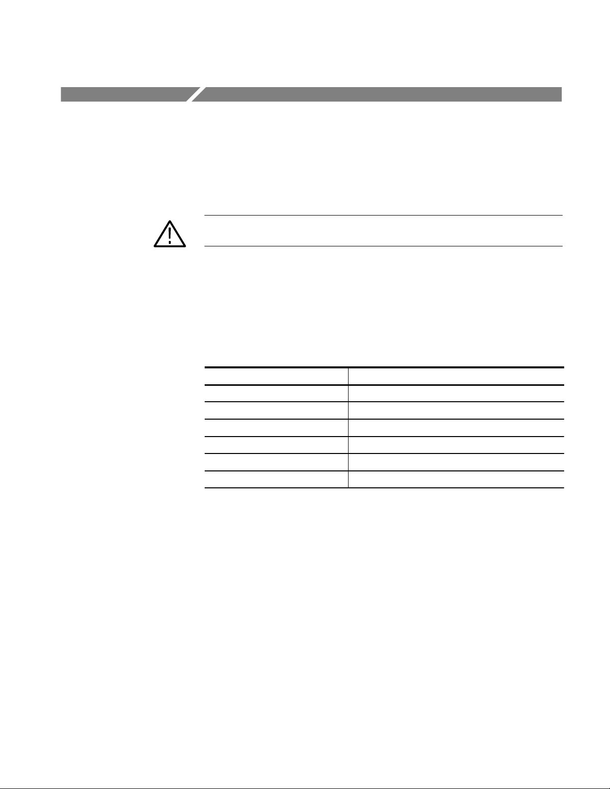
Removal and Replacement
This section explains how to remove and replace the field replaceable modules of
the WVR500 monitor. All field replaceable parts are listed in the Replaceable
Parts section, which begins on page 8–1.
WARNING. Disconnect the power cord from the instrument before attempting any
disassembly procedures.
Required Tools
Top Cover
The following tools are required to completely disassemble the WVR500
monitor to its modules. Some of these tools are only required for removal of
specific instrument components.
T able 6–1: Required tools for module removal and replacement
Name Description
Screwdriver handle Accepts POZIDRIV bits
Torque driver Accepts POZIDRIV bits; can be set up to 4ft-lb
POZIDRIV tip POZIDRIV bit for screw heads
3/16-inch Nut-driver Used for Serial Filter board removal
Hex wrench, 1/16 inch Used for knob removal
Soldering Iron 15 W. Used for removing the Main board
To remove the top cover:
1. Remove the 11 screws from the top cover. See Figure 6–1.
2. Carefully lift the top cover off the bottom cover assembly.
To replace the top cover:
1. Place the top cover on the bottom cover assembly. Check that the plastic
power supply shield is tucked inside the bottom cover assembly and under
the tab near the Serial Filter board, and that the silkscreen label on the top
cover is over the power plug.
2. Insert the (11) machine screws through the top cover into the bottom cover
assembly. Tighten the screws using a torque driver set to 4 ft-lb.
WVR500 Waveform/Vector Monitor Service Manual
6–7
Page 100

Removal and Replacement
Top cover
Screws (11)
Figure 6–1: Removing the top cover
Front Panel Assembly
To remove the front-panel assembly from the bottom-cover assembly:
1. Remove the top cover following the instructions on page 6–7.
2. Disconnect the front-panel assembly cable from A2J22 on the Main board.
3. Remove the two screws from the underside of the bottom cover. See
Figure 6–2.
To reattach the front panel assembly to the bottom cover:
1. Line up the tabs on the front panel assembly with the two holes in the
bottom cover.
2. Insert the two screws through the underside of the bottom cover into the
front panel assembly tabs. Tighten the screws using a torque driver set to
4 ft–lb.
3. Reconnect the front panel cable to the A2J22 connector on the Main board.
4. Replace the top cover by following the instructions on page 6–7.
6–8
WVR500 Waveform/Vector Monitor Service Manual
 Loading...