

Page 1

Instruction Manual
TMS 871
1394 Bus Support Package
071-0637-00
There are no current European directives that
apply to this product. This product provides
cable and test lead connections to a test object of
electronic measuring and test equipment.
Warning
The servicing instructions are for use by
qualified personnel only. To avoid personal
injury, do not perform any servicing unless you
are qualified to do so. Refer to all safety
summaries prior to performing service.
Page 2

Copyright E T ektronix, Inc. All rights reserved. Licensed software products are owned by Tektronix or its suppliers and are protected by United States copyright laws and international treaty provisions.
Use, duplication, or disclosure by the Government is subject to restrictions as set forth in subparagraph (c)(1)(ii) of the
Rights in T echnical Data and Computer Software clause at DFARS 252.227-7013, or subparagraphs (c)(1) and (2) of the
Commercial Computer Software – Restricted Rights clause at F AR 52.227-19, as applicable.
T ektronix products are covered by U.S. and foreign patents, issued and pending. Information in this publication supercedes
that in all previously published material. Specifications and price change privileges reserved.
T ektronix, Inc., P.O. Box 1000, Wilsonville, OR 97070–1000
TEKTRONIX and TEK are registered trademarks of T ektronix, Inc.
Page 3

SOFTWARE WARRANTY
T ektronix warrants that the media on which this software product is furnished and the encoding of the programs on
the media will be free from defects in materials and workmanship for a period of three (3) years from the date of
shipment. If a medium or encoding proves defective during the warranty period, T ektronix will provide a
replacement in exchange for the defective medium. Except as to the media on which this software product is
furnished, this software product is provided “as is” without warranty of any kind, either express or implied.
T ektronix does not warrant that the functions contained in this software product will meet Customer’s
requirements or that the operation of the programs will be uninterrupted or error-free.
In order to obtain service under this warranty, Customer must notify Tektronix of the defect before the expiration
of the warranty period. If T ektronix is unable to provide a replacement that is free from defects in materials and
workmanship within a reasonable time thereafter, Customer may terminate the license for this software product
and return this software product and any associated materials for credit or refund.
THIS WARRANTY IS GIVEN BY TEKTRONIX IN LIEU OF ANY OTHER WARRANTIES, EXPRESS
OR IMPLIED. TEKTRONIX AND ITS VENDORS DISCLAIM ANY IMPLIED WARRANTIES OF
MERCHANTABILITY OR FITNESS FOR A PARTICULAR PURPOSE. TEKTRONIX’
RESPONSIBILITY TO REPLACE DEFECTIVE MEDIA OR REFUND CUSTOMER’S PAYMENT IS
THE SOLE AND EXCLUSIVE REMEDY PROVIDED TO THE CUSTOMER FOR BREACH OF THIS
WARRANTY. TEKTRONIX AND ITS VENDORS WILL NOT BE LIABLE FOR ANY INDIRECT,
SPECIAL, INCIDENTAL, OR CONSEQUENTIAL DAMAGES IRRESPECTIVE OF WHETHER
TEKTRONIX OR THE VENDOR HAS ADVANCE NOTICE OF THE POSSIBILITY OF SUCH
DAMAGES.
Page 4

HARDWARE WARRANTY
T ektronix warrants that the products that it manufactures and sells will be free from defects in materials and
workmanship for a period of one (1) year from the date of shipment. If a product proves defective during this
warranty period, T ektronix, at its option, either will repair the defective product without charge for parts and labor,
or will provide a replacement in exchange for the defective product.
In order to obtain service under this warranty, Customer must notify Tektronix of the defect before the expiration
of the warranty period and make suitable arrangements for the performance of service. Customer shall be
responsible for packaging and shipping the defective product to the service center designated by T ektronix, with
shipping charges prepaid. Tektronix shall pay for the return of the product to Customer if the shipment is to a
location within the country in which the T ektronix service center is located. Customer shall be responsible for
paying all shipping charges, duties, taxes, and any other charges for products returned to any other locations.
This warranty shall not apply to any defect, failure or damage caused by improper use or improper or inadequate
maintenance and care. T ektronix shall not be obligated to furnish service under this warranty a) to repair damage
resulting from attempts by personnel other than T ektronix representatives to install, repair or service the product;
b) to repair damage resulting from improper use or connection to incompatible equipment; c) to repair any
damage or malfunction caused by the use of non-T ektronix supplies; or d) to service a product that has been
modified or integrated with other products when the effect of such modification or integration increases the time
or difficulty of servicing the product.
THIS WARRANTY IS GIVEN BY TEKTRONIX IN LIEU OF ANY OTHER WARRANTIES, EXPRESS
OR IMPLIED. TEKTRONIX AND ITS VENDORS DISCLAIM ANY IMPLIED WARRANTIES OF
MERCHANTABILITY OR FITNESS FOR A PARTICULAR PURPOSE. TEKTRONIX’
RESPONSIBILITY TO REPAIR OR REPLACE DEFECTIVE PRODUCTS IS THE SOLE AND
EXCLUSIVE REMEDY PROVIDED TO THE CUST OMER FOR BREACH OF THIS WARRANTY.
TEKTRONIX AND ITS VENDORS WILL NOT BE LIABLE FOR ANY INDIRECT , SPECIAL,
INCIDENTAL, OR CONSEQUENTIAL DAMAGES IRRESPECTIVE OF WHETHER TEKTRONIX OR
THE VENDOR HAS ADVANCE NOTICE OF THE POSSIBILITY OF SUCH DAMAGES.
Page 5

Table of Contents
Getting Started
Operating Basics
Preface ix. . . . . . . . . . . . . . . . . . . . . . . . . . . . . . . . . . . . . . . . . . . . . . . . . . .
Manual Conventions ix. . . . . . . . . . . . . . . . . . . . . . . . . . . . . . . . . . . . . . . . . . . . . .
Logic Analyzer Documentation ix. . . . . . . . . . . . . . . . . . . . . . . . . . . . . . . . . . . . . .
Contacting T ektronix x. . . . . . . . . . . . . . . . . . . . . . . . . . . . . . . . . . . . . . . . . . . . . .
Support Description 1–2. . . . . . . . . . . . . . . . . . . . . . . . . . . . . . . . . . . . . . . . . . . . . . .
Logic Analyzer Software Compatibility 1–2. . . . . . . . . . . . . . . . . . . . . . . . . . . . . . .
Standard Accessories 1–2. . . . . . . . . . . . . . . . . . . . . . . . . . . . . . . . . . . . . . . . . . . . . .
Options 1–2. . . . . . . . . . . . . . . . . . . . . . . . . . . . . . . . . . . . . . . . . . . . . . . . . . . . . . . . .
Requirements and Restrictions 1–3. . . . . . . . . . . . . . . . . . . . . . . . . . . . . . . . . . . . . . .
Connecting to a System Under T est 1–3. . . . . . . . . . . . . . . . . . . . . . . . . . . . . . . . . . .
Setting Up the Support 2–1. . . . . . . . . . . . . . . . . . . . . . . . . . . . . . . . . . . . . .
Channel Group Definitions 2–1. . . . . . . . . . . . . . . . . . . . . . . . . . . . . . . . . . . . . . . . .
Symbols 2–2. . . . . . . . . . . . . . . . . . . . . . . . . . . . . . . . . . . . . . . . . . . . . . . . . . . . . . . .
Acquiring and Viewing Data 2–7. . . . . . . . . . . . . . . . . . . . . . . . . . . . . . . . .
Acquiring Data 2–7. . . . . . . . . . . . . . . . . . . . . . . . . . . . . . . . . . . . . . . . . . . . . . . . . . .
Trigger Setups 2–7. . . . . . . . . . . . . . . . . . . . . . . . . . . . . . . . . . . . . . . . . . . . . . . . . . .
Custom Clocking 2–9. . . . . . . . . . . . . . . . . . . . . . . . . . . . . . . . . . . . . . . . . . . . . . . . .
Display Options 2–10. . . . . . . . . . . . . . . . . . . . . . . . . . . . . . . . . . . . . . . . . . . . . . . . . .
Displaying Data 2–11. . . . . . . . . . . . . . . . . . . . . . . . . . . . . . . . . . . . . . . . . . . . . . . . . .
1394 Bus Packets 2–16. . . . . . . . . . . . . . . . . . . . . . . . . . . . . . . . . . . . . . . . . . . . . . . . .
Specifications
Probe Adapter Description 3–1. . . . . . . . . . . . . . . . . . . . . . . . . . . . . . . . . . . . . . . . . .
Probe Adapter Functions 3–2. . . . . . . . . . . . . . . . . . . . . . . . . . . . . . . . . . . . . . . . . . .
Specifications 3–2. . . . . . . . . . . . . . . . . . . . . . . . . . . . . . . . . . . . . . . . . . . . . . . . . . . .
Channel Assignments 3–4. . . . . . . . . . . . . . . . . . . . . . . . . . . . . . . . . . . . . . . . . . . . . .
Signal Descriptions 3–9. . . . . . . . . . . . . . . . . . . . . . . . . . . . . . . . . . . . . . . . . . . . . . .
Functional Verification
Functional Verification 4–1. . . . . . . . . . . . . . . . . . . . . . . . . . . . . . . . . . . . . .
Probe Adapter Circuit Description 4–1. . . . . . . . . . . . . . . . . . . . . . . . . . . . . . . . . . . .
Equipment Required 4–1. . . . . . . . . . . . . . . . . . . . . . . . . . . . . . . . . . . . . . . . . . . . . . .
Verifying Clock Activity Using an Oscilloscope 4–2. . . . . . . . . . . . . . . . . . . . . . . . .
Verifying Probe Adapter Functionality with the TLA System Activity Monitor 4–3
Troubleshooting 4–4. . . . . . . . . . . . . . . . . . . . . . . . . . . . . . . . . . . . . . . . . . . . . . . . . .
Replaceable Parts
Parts Ordering Information 5–1. . . . . . . . . . . . . . . . . . . . . . . . . . . . . . . . . . . . . . . . .
Using the Replaceable Parts List 5–1. . . . . . . . . . . . . . . . . . . . . . . . . . . . . . . . . . . . .
TMS 871 1394 Bus Support Package Instruction Manual
i
Page 6

Table of Contents
List of Figures
Figure 1–1: TMS 871 support package 1–1. . . . . . . . . . . . . . . . . . . . . . . . .
Figure 1–2: Connecting the cables to the probe adapter 1–4. . . . . . . . . . .
Figure 1–3: Complete test setup 1–5. . . . . . . . . . . . . . . . . . . . . . . . . . . . . . .
Figure 2–1: Trigger Setup Window 2–8. . . . . . . . . . . . . . . . . . . . . . . . . . . .
Figure 2–2: All Fields Display 2–12. . . . . . . . . . . . . . . . . . . . . . . . . . . . . . . .
Figure 2–3: Selected Fields Display 2–13. . . . . . . . . . . . . . . . . . . . . . . . . . . .
Figure 2–4: Truncated Data in a Selected Field 2–14. . . . . . . . . . . . . . . . . .
Figure 2–5: Packet Header Display 2–15. . . . . . . . . . . . . . . . . . . . . . . . . . . .
Figure 2–6: Packet Type Display 2–16. . . . . . . . . . . . . . . . . . . . . . . . . . . . . .
Figure 3–1: Dimensions of the probe adapter 3–3. . . . . . . . . . . . . . . . . . . .
Figure 4–1: SCLK/2 (system clock) signal test point 4–2. . . . . . . . . . . . . .
Figure 4–2: Activity pattern 4–3. . . . . . . . . . . . . . . . . . . . . . . . . . . . . . . . . .
ii
TMS 871 1394 Bus Support Package Instruction Manual
Page 7

List of Tables
Table of Contents
Table 2–1: Displayed Channel Groups 2–1. . . . . . . . . . . . . . . . . . . . . . . . .
Table 2–2: Error group symbol table definitions 2–2. . . . . . . . . . . . . . . .
Table 2–3: Event group symbol table definitions 2–3. . . . . . . . . . . . . . . .
Table 2–4: PCtrl group symbol table definitions 2–3. . . . . . . . . . . . . . . . .
Table 2–5: Speed group symbol table definitions 2–4. . . . . . . . . . . . . . . .
Table 2–6: Type group symbol table definitions 2–4. . . . . . . . . . . . . . . . .
Table 2–7: Last_Data group symbol table definitions 2–5. . . . . . . . . . . . .
Table 2–8: Tcode group symbol table definitions 2–5. . . . . . . . . . . . . . . .
Table 3–1: Electrical specifications 3–2. . . . . . . . . . . . . . . . . . . . . . . . . . . .
Table 3–2: Environmental specifications* 3–3. . . . . . . . . . . . . . . . . . . . . .
Table 3–3: Certifications and compliances 3–3. . . . . . . . . . . . . . . . . . . . . .
Table 3–4: Channel group display order 3–4. . . . . . . . . . . . . . . . . . . . . . .
Table 3–5: Quad_Data group assignments 3–5. . . . . . . . . . . . . . . . . . . . . .
Table 3–6: Speed group assignments 3–6. . . . . . . . . . . . . . . . . . . . . . . . . .
Table 3–7: Type group assignments 3–6. . . . . . . . . . . . . . . . . . . . . . . . . . .
Table 3–8: Event group assignments 3–6. . . . . . . . . . . . . . . . . . . . . . . . . .
Table 3–9: Error group assignments 3–7. . . . . . . . . . . . . . . . . . . . . . . . . . .
Table 3–10: Count group assignments 3–7. . . . . . . . . . . . . . . . . . . . . . . . .
Table 3–11: Last_Data group assignments 3–7. . . . . . . . . . . . . . . . . . . . . .
Table 3–12: Phy_Data group assignments 3–8. . . . . . . . . . . . . . . . . . . . . .
Table 3–13: Phy_Ctrl group assignments 3–8. . . . . . . . . . . . . . . . . . . . . . .
Table 3–14: Clock and qualifier channel assignments 3–8. . . . . . . . . . . .
Table 3–15: Signal descriptions 3–9. . . . . . . . . . . . . . . . . . . . . . . . . . . . . . .
Table 4–1: Equipment list 4–1. . . . . . . . . . . . . . . . . . . . . . . . . . . . . . . . . . .
TMS 871 1394 Bus Support Package Instruction Manual
iii
Page 8

Table of Contents
iv
TMS 871 1394 Bus Support Package Instruction Manual
Page 9

General Safety Summary
Review the following safety precautions to avoid injury and prevent damage to
this product or any products connected to it. To avoid potential hazards, use this
product only as specified.
Only qualified personnel should perform service procedures.
To Avoid Fire or Personal Injury
Symbols and Terms
Connect and Disconnect Properly . Connect the probe output to the measurement
instrument before connecting the probe to the circuit under test. Disconnect the
probe input from the circuit under test before disconnecting the probe from the
measurement instrument.
Observe All Terminal Ratings. To avoid fire or shock hazard, observe all ratings
and marking on the product. Consult the product manual for further ratings
information before making connections to the product.
Do Not Operate With Suspected Failures. If you suspect there is damage to this
product, have it inspected by qualified service personnel.
Do Not Operate in Wet/Damp Conditions.
Do Not Operate in an Explosive Atmosphere.
Keep Product Surfaces Clean and Dry .
T erms in this Manual. These terms may appear in this manual:
WARNING. Warning statements identify conditions or practices that could result
in injury or loss of life.
CAUTION. Caution statements identify conditions or practices that could result in
damage to this product or other property.
TMS 871 1394 Bus Support Package Instruction Manual
v
Page 10

General Safety Summary
T erms on the Product. These terms may appear on the product:
DANGER indicates an injury hazard immediately accessible as you read the
marking.
WARNING indicates an injury hazard not immediately accessible as you read the
marking.
CAUTION indicates a hazard to property including the product.
Symbols on the Product. The following symbols may appear on the product:
Protective Ground
(Earth) T erminal
CAUTION
Refer to Manual
Double
Insulated
vi
TMS 871 1394 Bus Support Package Instruction Manual
Page 11

Service Safety Summary
Only qualified personnel should perform service procedures. Read this Service
Safety Summary and the General Safety Summary before performing any service
procedures.
Do Not Service Alone. Do not perform internal service or adjustments of this
product unless another person capable of rendering first aid and resuscitation is
present.
Disconnect Power. To avoid electric shock, disconnect the main power by means
of the power cord or, if provided, the power switch.
Use Care When Servicing With Power On. Dangerous voltages or currents may
exist in this product. Disconnect power, remove battery (if applicable), and
disconnect test leads before removing protective panels, soldering, or replacing
components.
To avoid electric shock, do not touch exposed connections.
TMS 871 1394 Bus Support Package Instruction Manual
vii
Page 12

Service Safety Summary
viii
TMS 871 1394 Bus Support Package Instruction Manual
Page 13

Preface
This instruction manual contains specific information about the TMS 871 1394
Bus support package and is part of a set of information on how to operate this
product on compatible Tektronix logic analyzers.
If you are familiar with operating support packages on the logic analyzer for
which the TMS 871 1394 Bus support was purchased, you will probably only
need this instruction manual to set up and run the support.
If you are not familiar with operating support packages, you will need to
supplement this instruction manual with information on basic operations to set up
and run the support.
Each logic analyzer has basic information that describes how to perform tasks
common to support packages on that platform. This information can be in the
form of online help, an installation manual, or a user manual. For complete
information on packet types and field descriptions, refer to the IEEE 1394_1995
Standard and the IEEE 1394a supplement.
This manual provides detailed information on the following topics:
H Connecting the logic analyzer to the system under test
H Setting up the logic analyzer to acquire data from the system under test
H Acquiring and viewing data
H Using the probe adapter
Manual Conventions
This manual uses the following conventions:
H The term “system under test (SUT)” refers to the 1394 Bus system from
which data will be acquired.
H The term “logic analyzer” refers to the Tektronix logic analyzer for which
this product was purchased.
H The term “module” refers to the Tektronix logic analyzer module for which
this product was purchased.
Logic Analyzer Documentation
A description of other documentation available for each type of Tektronix logic
analyzer is located in the corresponding module user manual. The manual set
provides the information necessary to install, operate, maintain, and service the
logic analyzer and associated products.
TMS 871 1394 Bus Support Package Instruction Manual
ix
Page 14

Preface
Contacting Tektronix
Product
Support
Service
Support
For other
information
To write us
Website
For questions about using Tektronix measurement products, call
toll free in North America:
1-800-TEK-WIDE (1-800-835-9433 ext. 2400)
6:00 a.m. – 5:00 p.m. Pacific time
Or contact us by e-mail:
tm_app_supp@tek.com
For product support outside of North America, contact your
local Tektronix distributor or sales office.
Tektronix offers extended warranty and calibration programs as
options on many products. Contact your local Tektronix
distributor or sales office.
For a listing of worldwide service centers, visit our web site.
In North America:
1-800-TEK-WIDE (1-800-835-9433)
An operator will direct your call.
Tektronix, Inc.
P.O. Box 1000
Wilsonville, OR 97070-1000
USA
Tektronix.com
x
TMS 871 1394 Bus Support Package Instruction Manual
Page 15

Getting Started
This chapter provides information on the following topics and tasks:
H A description of the TMS 871 1394 Bus support package
H Logic analyzer software compatibility
H Options and accessories
H Support restrictions
H How to connect to the system under test
Figure 1–1 shows components of the TMS 871 1394 Bus support package.
Figure 1–1: TMS 871 support package
TMS 871 1394 Bus Support Package Instruction Manual
1–1
Page 16

Getting Started
Support Description
The TMS 871 1394 Bus support package displays data from the IEEE 1394 High
Performance Serial Bus. The support runs on a compatible Tektronix logic
analyzer equipped with a 68-channel or wider module, and requires two P6434
probes.
A complete list of standard and optional accessories is provided at the end of the
parts list in the Replaceable Mechanical Parts chapter.
Logic Analyzer Software Compatibility
The TMS 871 application software requires Version 3.0 and higher of TLA 700
System software running on the logic analyzer, and Version 3.0 and higher of
TLA 700 LA module firmware on the modules you will be using.
Standard Accessories
Options
The probe adapter is shipped with the following standard accessories:
H TMS 871 Support SW Disk
H TMS 871 Support Instruction Manual
H 1394 cable
H 5V power supply
H North American power cord
The following options are available when ordering the TMS 871 Support:
H Option A1 Power Cord, Europe, 230 V
H Option A2 Power Cord, United Kingdom, 230 V
H Option A3 Power Cord, Australia, 230 V
H Option A5 Power Cord, Switzerland, 230 V
H Option 21 Add 2 P6434 Probes
1–2
TMS 871 1394 Bus Support Package Instruction Manual
Page 17

Requirements and Restrictions
You should review the general requirements and restrictions of 1394 Bus support
in the information on basic operations.
You should also review electrical, environmental, and mechanical specifications
in the Specifications chapter in this manual as they pertain to your system under
test, as well as the following descriptions of other support requirements and
restrictions.
Getting Started
System Clock Rate
Merged Module Pair
The TMS 871 support package can acquire data from the 1394 bus operating at
speeds of 100, 200, or 400 Mb/s.
If you have a pair of modules that are merged in the logic analyzer, you can
un-merge them (and use either one). If you want the modules to remain merged,
then the probe adapter must connect to the master module.
Connecting to a System Under Test
To connect the logic analyzer to the probe adapter, follow these steps:
CAUTION. Static discharge can damage the probe adapter, the probes, or the
module. To prevent static damage, handle all of these products only in a
static-free environment.
1. Plug the power supply into an appropriate power source.
2. Connect the DC plug to the probe adapter to provide power to the probe
adapter.
3. Connect the P6434 probes to the 1394 probe adapter. Align the probe tip with
the mating connector and gently connect as shown in Figure 1–2.
TMS 871 1394 Bus Support Package Instruction Manual
1–3
Page 18

Getting Started
Push down to latch after
probe is connected
Pin 1
Figure 1–2: Connecting the cables to the probe adapter
CAUTION. Incorrect handling of the P6434 probe while connecting it to the probe
adapter can result in damage to the probe or to the mating connector on the
probe adapter. To avoid damaging the probe and probe adapter, always position
the probe perpendicular to the mating connector and gently connect the probe.
4. Connect the module ends of the P6434 probes to the corresponding connec-
tors on the logic analyzer. The probe module ends are keyed.
NOTE. The right-side P6434 probe (as seen from the rear of the probe adapter)
connects to D1–D0 and C3–C2 connectors on the logic analyzer. This may not
match the color coding on a pre-labeled P6434 probe.
5. Connect the 1394 probe adapter to the 1394 system under test using the 6-pin
1394 cable supplied with the probe adapter, or any standard 6-pin 1394
cable. Use any of the three ports on the front of the probe adapter.
6. The complete test setup appears in Figure 1–3 on page 1–5.
1–4
TMS 871 1394 Bus Support Package Instruction Manual
Page 19

To Logic Analyzer
Getting Started
P6434 Probes (2)
To power
supply
TMS 871
To SUT
1394 Cable
Figure 1–3: Complete test setup
TMS 871 1394 Bus Support Package Instruction Manual
1–5
Page 20

Getting Started
1–6
TMS 871 1394 Bus Support Package Instruction Manual
Page 21

Setting Up the Support
This section describes how to set up the support and includes these topics:
H Channel group definitions
H Symbol table files
Remember that the information in this section is specific to the operations and
functions of the TMS 871 support package. Information on basic operations
describes general tasks and functions.
Before you acquire and display data, you need to load the support and specify
setups for clocking and triggering as described in the information on basic
operations. The support provides default values for each of these setups, but you
can change them as needed.
Channel Group Definitions
The software automatically defines channel groups for the support.
Channel Groups
The defined channel groups are Data, Speed, Type, Event, Error, Count,
Last_Data, Phy_Data, and Phy_Ctrl.
To see which signal is in which channel group, refer to the channel group
assignment tables beginning on page 2–2. Tables 2–2 through 2–6 show the
channel assignments for the setup.
T able 2–1: Displayed Channel Groups
Group name Display radix
Data HEX
Mnemonic NONE (disassembly text generated by support)
Speed SYM
Type SYM
Event SYM
Error SYM
Count DEC
Last_Data SYM
Phy_Data HEX
Phy_Ctrl SYM
1
1
1
1
1
1
Timestamp
1
These groups are acquired but not displayed in a default listing. They may be added
to the listing window by the user.
TMS 871 1394 Bus Support Package Instruction Manual
2–1
Page 22

Setting Up the Support
Symbols
The TMS 871 support supplies the following seven symbol table files:
H 1394_Error.tsf
H 1394_Event.tsf
H 1394_PCtrl.tsf
H 1394_Speed.tsf
H 1394_Type.tsf
H 1394_Last.tsf
H 1394_Tcode.tsf
Each file replaces specific channel group values with symbolic values when
Symbolic is the radix for the channel group.
Error Group
The symbol table file for the Error group is 1394_Error.
The error group represents hardware errors that can occur on the bus. The symbol
table shows the error code for the corresponding signal that was set. Multiple
errors are not covered by the table.
Table 2–2 shows the 1394_Error symbol table.
T able 2–2: Error group symbol table definitions
Error group value
Iso_Cycle_Lost
Cyc_Too_Long
State_Timeout
Quad_Align_Err
Symbol
-- 000000 No Error
ISO_LOST 100000 Isochronous cycle did not complete
ISO_LONG 010000 Isochronous cycle exceeds maximum time
TIMEOUT 001000 Phy stayed in one state too long
ALIGN_ERR 000100 Quad data not ending on quadlet boundary
ACK_ERR 000010 2nd nibble of ACK not logical inverse
SLFPKT_ERR 000001 2nd quadlet of self-ID pkt not logical inverse
Ack_Err
Self_Packet_Err
Description
2–2
TMS 871 1394 Bus Support Package Instruction Manual
Page 23

Setting Up the Support
Event Group
The symbol table file for the Event group is 1394_Event.
The event group collects the validation strobe that, with SysClk, determine the
packet is valid. The events are grouped for displaying added information in the
listing and for triggering use.
Table 2–3 shows the 1394_Event symbol table.
T able 2–3: Event group symbol table definitions
Event group value
Arb_Gap
Sub_Gap
Data_Rdy
Ack_Rcvd
Symbol
-- 000000 No event
ARB_GAP 100000 Arbitration gap detected
SUB_GAP 010000 Subaction gap detected
DA TA_RDY 001000 Quadlet data is valid
ACK_RCVD 000 100 Acknowledge data is valid
HW_ERROR 000010 Hardware error has occured
RESET XXXXX1 Bus reset detected
Reset
HW_Error
Description
PCtrl Group
The symbol table file for the PCtrl group is 1394_PCtrl.
The PCtrl group represents the PHY CTL signals as defined by 1394a. This
group is not normally displayed. The information is for those advanced users
who wish to look at the signals immediately available at the PHY-Link interface.
Table 2–4 shows the 1394_PCtrl symbol table.
T able 2–4: PCtrl group symbol table definitions
PCtrl group value
Symbol
IDLE 00 No activity
ST ATUS 10 PHY sending status info to link
RECEIVE 01 Packets being received
GRANT 00 PHY granting bus to link
Phy_Ctrl_0
Phy_Ctrl_1
Description
TMS 871 1394 Bus Support Package Instruction Manual
2–3
Page 24

Setting Up the Support
Speed Group
Type Group
The symbol table file for the Speed group is 1394_Speed.
The speed group indicates the bus speed as 100, 200, or 400 Mb/s.
Table 2–5 shows the 1394_Speed symbol table.
T able 2–5: Speed group symbol table definitions
Speed group value
Value
100 00 Speed is 100 Mb/s
200 10 Speed is 200 Mb/s
400 01 Speed is 400 Mb/s
– 11 Undefined
Speed_0
Speed_1
Description
The symbol table file for the Type group is 1394_Type.
The type group represents a collection of special packet identification signals.
Table 2–6 shows the 1394_Type symbol table.
T able 2–6: Type group symbol table definitions
Type group value
Bcast_Packet
Symbol
-- 000 Other packet type
BCAST 1XX Broadcast packet
SLFID X1X Self-Id packet
ISO XX1 Isochronous packet
Self_Id_Packet
Iso_Cyc
Description
2–4
TMS 871 1394 Bus Support Package Instruction Manual
Page 25

Setting Up the Support
Last_Data Group
Tcode Group
The symbol table file for the Last_Data group is 1394_Last.
The Last_Data symbols label the one bit (last data quadlet in a packet) as true or
false to clarify usage in Trigger Setups.
Table 2–7 shows the 1394_Last symbol table.
T able 2–7: Last_Data group symbol table definitions
Value
True 1
False 0
Last_Rx_Data
The symbol table file for the Tcode group is 1394_Tcode. It is used for trigger
setup to identify transaction codes in the Data group on the first quadlet of a
packet.
Table 2–8 shows the 1394_Tcode symbol table.
T able 2–8: Tcode group symbol table definitions
Tcode group value
Symbol
WR_REQ_QUAD XXXXXX0X Write Request for Data Quadlet
WR_REQ_BLK XXXXXX1X Write Request for Data Block
WR_RESP XXXXXX2X Write Response
RD_REQ_QUAD XXXXXX4X Read Request for Data Quadlet
RD_REQ_BLK XXXXXX5X Read Request for Data Block
RD_RESP_QUAD XXXXXX6X Read Request for Data Quadlet
RD_RESP_BLK XXXXXX7X Read Response for Data Block
CYC_ST AR T XXXXXX8X Cycle Start
LOCK_REQ XXXXXX9X Lock Request
ISOCH XXXXXXAX Isochronous or Streaming Data
LOCK_RESP XXXXXXBX Lock Response
Tcode
Description
Information on basic operations describes how to modify an existing symbol
table, create new symbol tables, and use symbolic values for triggering and
displaying other channel groups symbolically, such as the Address channel
group.
TMS 871 1394 Bus Support Package Instruction Manual
2–5
Page 26

Setting Up the Support
2–6
TMS 871 1394 Bus Support Package Instruction Manual
Page 27

Acquiring and Viewing Data
This section describes how to acquire data and view it in a listing window with
the following topics and tasks:
H Acquiring data
H Trigger setups
H Clocking options
H Display options
H Displaying data
Acquiring Data
Once you load the 1394 setup, you can specify the trigger, choose a clocking
mode, and acquire data.
If you have any problems acquiring data, refer to information on basic operations
in your online help.
Trigger Setups
The signals available on the 1394 bus allow for many triggering possibilities.
The .tla files include trigger setting examples, which will be similar to the
example shown in Figure 2–1 on page 2–8.
TMS 871 1394 Bus Support Package Instruction Manual
2–7
Page 28

Acquiring and Viewing Data
Figure 2–1: Trigger Setup Window
This trigger/capture state machine model can be used for a wide variety of
situations. In this example, the default is to store everything with the State 1
being used to identify certain packet types by a specific tcode bit pattern in the
first quadlet of the packet. The Last_Data group is TRUE only on the last quadlet
which allows State 2 to exclude (not store) the entire packet identified in State 1.
In this example, all Cycle Start packets are excluded from being stored and the
logic analyzer is triggered on an Isochronous packet.
Note that the custom clocking options also allow the user to not store long packet
data, gaps, and errors. As there is a limit to the number of clauses in a trigger
state (typically 4), the custom clocking option should be examined for more
complex triggering/storage situations.
Using the model shown in Figure 2–1, some variations useful to 1394 might be:
H Group Speed (symbolic). Can exclude packets labeled with a speed code. For
example, all 100Mb/s packets can be excluded. State 2 is not needed.
H Group Event (symbolic for event). Singles out specific types of qualifying
events. Overlaps custom clocking for gaps and errors. Useful for identifying
trigger point, such as triggering on a bus reset.
2–8
TMS 871 1394 Bus Support Package Instruction Manual
Page 29

Acquiring and Viewing Data
H Group Count>n. Can be used to store only the first n bytes of the packet.
State 2 is not needed. Note that this is covered for a value of 16 by a custom
clocking option.
H Type (symbolic for type). Allows broadcast, self-id packets, or iso packets to
be excluded. For more information, refer to Tables 3–7 and 3–13 on pages
3–6 and 3–8 for a description of the signals in this group. State 2 is not
needed.
H Group Count=1 and Group Data=(symbolic for tcode). Allows various
packet types to be excluded from storage. Used with State 2.
H Group Error=(symbolic for error). Singles out a specific type of error to not
store or to trigger on. State 2 is not needed.
H Group Count=n and Group Data=HEX. Generic way to specify a packet by
information known to be in a certain byte. For example, the destination
address which is the first 16 bytes of the first quadlet for several different
packet types. Used with State 2 to exclude capture from the identified
quadlet through the end of the packet.
Custom Clocking
Clocking Mode
The TMS 871 will add the selection 1394 to the Load Support Package dialog
box, under the File pulldown menu. Once the 1394 support has been loaded, the
Custom clocking mode selection in the logic analyzer Setup menu is also
enabled. Custom will be the default selection whenever the 1394 support has
been loaded.
When Custom is selected, the TMS 871 support will modify the Custom
Clocking Options menu to display three options:
H Clocking Mode
H Quadlet Capture
H Packet Truncation
The selections for these three options are defined below.
The Clocking Mode option allows the user to select either Normal or Raw Phy
modes of clocking. Normal mode is used for disassembly and for all groups
except Phy_Data and Phy_Ctrl. In Normal mode, different clock options are
available.
Raw Phy mode clocks at twice the rate of Normal mode (the Phy-Link SCLK
signal rate) and is used for acquiring the low-level Phy_Ctrl and Phy_Data group
signals only. Because of the different clocking, other group values may or may
TMS 871 1394 Bus Support Package Instruction Manual
2–9
Page 30

Acquiring and Viewing Data
not be valid when acquired. Raw Phy mode is not useful for disassembly. When
this mode is selected, the settings of the other two clocking options have no
effect.
Quadlet Capture
Packet Truncation
There are four quadlet capture selections possible, listed below. These only take
effect when the Clocking Mode is set to Normal. The All Valid selection is the
default.
H All Valid. The all valid selection qualifies quadlets for acquisition by looking
for a Data_Rdy, Arb_Gap, Sub_Gap, Ack_Rcvd, HW_Error, or Reset signal
in the Event group (see Table 3–8 on page 3–6). This selection captures all
the valid quadlets which include gaps, acks, and errors.
H All Valid, no gaps. Same as All Valid except Arb_Gap and Sub_Gap events
are not captured.
H All Valid, no errors. Same as All Valid except errors (HW_errors) are not
captured.
H All Valid, no gaps or errors. Same as All Valid except no gaps or errors are
captured.
There are two selections possible here: None and After 16 quadlets. None is the
default. These only take effect when the Clocking Mode is set to Normal.
H None. There is no attempt to truncate packets.
H After 16 quadlets. Only quadlets up to and including the 16th quadlet in each
packet will be captured in this mode.
Display Options
2–10
The TMS 871 disassembles the fields of the packets specified in 1394-1995 and
1394a standards. The TMS 871 displays various levels of packet detail as
selected by choosing one of five disassembly modes as described in Displaying
Data on page 2–11.
TMS 871 1394 Bus Support Package Instruction Manual
Page 31

Displaying Data
Acquiring and Viewing Data
There are six formats to display 1394 bus cycles:
H Waveform (Timing)
H Listing (State):
H All Fields
H Selected Fields
H Truncated Data
H Packet Header
H Packet Type
All Listing modes are available through the Disassembly Properties menu of the
Listing display.
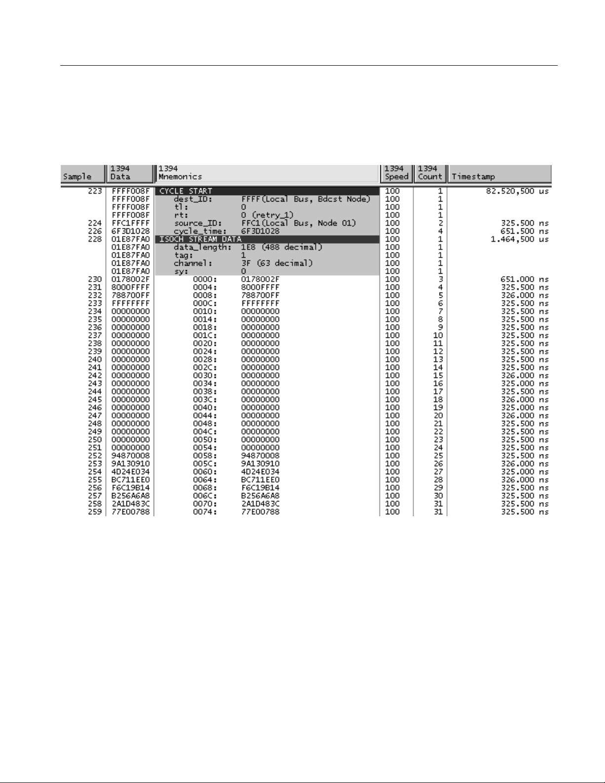
All Fields
All captured data (packet data, packet header, gaps, errors, and ack data) will be
displayed in this mode. Refer to Figure 2–2 on page 2–12.
All numeric values in the 1394 Mnemonics column are in hexadecimal, unless
otherwise specified.
TMS 871 1394 Bus Support Package Instruction Manual
2–11
Page 32

Acquiring and Viewing Data
Figure 2–2: All Fields Display
2–12
TMS 871 1394 Bus Support Package Instruction Manual
Page 33
Acquiring and Viewing Data
Selected Fields
In this mode, only the most significant packet header data fields will be displayed
and/or disassembled, along with all data. Gaps will not be displayed, nor will
header or data CRC’s. Ack data and errors will be displayed. Refer to Figure 2–3.
Figure 2–3: Selected Fields Display
TMS 871 1394 Bus Support Package Instruction Manual
2–13
Page 34

Acquiring and Viewing Data
Truncated Data
This mode displays selected fields, but only the first 16 data quadlets of any data
field. Refer to Figure 2–4.
Figure 2–4: Truncated Data in a Selected Field
2–14
TMS 871 1394 Bus Support Package Instruction Manual
Page 35

Acquiring and Viewing Data
Packet Header
This mode displays the selected header fields, without data quadlets. Refer to
Figure 2–5.
Figure 2–5: Packet Header Display
TMS 871 1394 Bus Support Package Instruction Manual
2–15
Page 36

Acquiring and Viewing Data
Packet Type
Figure 2–6: Packet Type Display
1394 Bus Packets
This mode displays errors and Ack data, but only one line for each packet (packet
type) is displayed . Refer to Figure 2–6.
Refer to the IEEE 1394_1995 Standard and the IEEE 1394a supplement for
complete information on packet types and field descriptions.
2–16
TMS 871 1394 Bus Support Package Instruction Manual
Page 37

Specifications
This chapter contains the following information:
H Probe adapter description
H Specification tables
H Channel assignment tables
H Signal descriptions
Probe Adapter Description
The probe adapter consists of an enclosed unit with three 6-pin connectors for
1394 Bus connections, and two 34-pin connectors for the LA interconnect (via
P6434 probes). Power is provided by an external power supply that plugs into the
back of the probe adapter. Signals from the 1394 Bus cable flow into the probe
adapter and through the P6434 probes to the logic analyzer.
All probe adapter circuitry is powered from an external power supply which must
supply 5-15 volts DC, at 350 milliamps maximum. The adapter has an internal
fuse and circuitry which protects against damage from reversed-polarity power
supply connections.
The probe adapter contains 3-port, 1394a-compliant PHY circuitry. The probe
adapter, following 1394 protocols, causes a bus reset when connected, when it
arbitrates for a node on the bus. Once connected, the probe adapter does not
generate any traffic from the Link layer, and does not expect any traffic to be
addressed to it.
After connecting, the probe adapter monitors all PHY-link data and conditions
the data with an on-board FPGA to generate signals for acquisition and triggering
by the logic analyzer.
The signals presented by the probe adapter to the logic analyzer are TTL level
with a clocking speed of 50 MHz or less. The probe adapter does not cause
excessive loading on critical signals.
TMS 871 1394 Bus Support Package Instruction Manual
3–1
Page 38

Specifications
Probe Adapter Functions
The probe adapter captures the following types of bus packets and events.
H Asynch Quadlet
H Isoch Quadlet
H Self ID Quadlet
H Phy Config Quadlet
H Ack Byte
H Arb Gap
H Sub-Action Gap
H Bus Reset
The following Hardware Errors are detected:
Specifications
H Isochronous cycle lost
H Isochronous cycle too long
H State timeout
H Quadlet alignment error
H Acknowledge packet error
H Self ID packet error
These specifications are for a probe adapter connected between a compatible
Tektronix logic analyzer and a 1394-1995 or 1394a-compliant device. The
system must be connected in a legal 1394 topology and running at S100, S200, or
S400 speeds. Table 3–1 shows the electrical requirements of the probe adapter in
order for the support to acquire correct data.
T able 3–1: Electrical specifications
Characteristics Requirements
Probe Adapter DC power requirements
5 V Vcc Voltage 4.75–5.25 VDC
5 V Vcc Current I max (calculated) 350 mA
3–2
TMS 871 1394 Bus Support Package Instruction Manual
Page 39

Specifications
Table 3–2 shows the environmental specifications.
T able 3–2: Environmental specifications*
Characteristic Description
Temperature
Maximum operating +50° C (+122° F)
Minimum operating 10° C (+50° F)
Non-operating –50° C to +75° C (–67° to +167° F)
* Designed to meet Tektronix standard 062-2847-00 class 5.
Table 3–3 shows the compliances that apply to the probe adapter.
T able 3–3: Certifications and compliances
EMC Compliance Meets the intent of Directive 89/336/EEC for Electromagnetic
Compatibility when it is used with the product(s) stated in the
specifications table. Refer to the EMC specification published for the
stated products. May not meet the intent of the directive if used with
other products.
FCC Compliance Emissions comply with FCC Code of Federal Regulations 47, Part 15,
Subpart B, Class A Limits.
Figure 3–1 shows the dimensions of the probe adapter.
34.29 mm
1.35 in
156.21 mm
99.98 mm
3.70 in
6.15 in
Figure 3–1: Dimensions of the probe adapter
TMS 871 1394 Bus Support Package Instruction Manual
3–3
Page 40

Specifications
Channel Assignments
Channel assignments shown in Table 3–5 through Table 3–14 use the following
conventions:
H All signals are required by the support unless indicated otherwise.
H Channels are shown starting with the most significant bit (MSB) descending
to the least significant bit (LSB). Note that 1394 convention labels the most
significant bit as zero.
H Section:channel refers to the module channel number.
The group assignment tables indicate whether the signal is required for custom
clocking and/or the disassembly. Required signals must be connected to properly
strobe and login bus data into acquisition memory, and to disassemble the
acquired bus data.
Channel groups will be displayed in the order shown in Table 3–4.
T able 3–4: Channel group display order
Group name Display radix
Data HEX
Mnemonic None (disassembly text generated by support package
software)
Speed SYM
Type SYM (default not displayed)
Event SYM (default not displayed)
Error SYM (default not displayed)
Count DEC
Last_Data SYM (default not displayed)
Phy_Data HEX (default not displayed)
Phy_Ctrl SYM (default not displayed)
Timestamp
3–4
TMS 871 1394 Bus Support Package Instruction Manual
Page 41

Specifications
Table 3–5 shows the probe section and channel assignments for the Quad group
and the signal to which each channel connects. By default, this channel group is
displayed in hexadecimal.
T able 3–5: Quad_Data group assignments
Required for clocking
Bit order Section:channel Signal name
31 A3:7 Data_0 Disassembly
30 A3:6 Data_1 Disassembly
29 A3:5 Data_2 Disassembly
28 A3:4 Data_3 Disassembly
27 A3:3 Data_4 Disassembly
26 A3:2 Data_5 Disassembly
25 A3:1 Data_6 Disassembly
24 A3:0 Data_7 Disassembly
23 A2:7 Data_8 Disassembly
22 A2:6 Data_9 Disassembly
21 A2:5 Data_10 Disassembly
20 A2:4 Data_11 Disassembly
19 A2:3 Data_12 Disassembly
18 A2:2 Data_13 Disassembly
17 A2:1 Data_14 Disassembly
16 A2:0 Data_15 Disassembly
15 A1:7 Data_16 Disassembly
14 A1:6 Data_17 Disassembly
13 A1:5 Data_18 Disassembly
12 A1:4 Data_19 Disassembly
11 A1:3 Data_20 Disassembly
10 A1:2 Data_21 Disassembly
9 A1:1 Data_22 Disassembly
8 A1:0 Data_23 Disassembly
7 A0:7 Data_24 Disassembly
6 A0:6 Data_25 Disassembly
5 A0:5 Data_26 Disassembly
4 A0:4 Data_27 Disassembly
3 A0:3 Data_28 Disassembly
2 A0:2 Data_29 Disassembly
1 A0:1 Data_30 Disassembly
0 A0:0 Data_31 Disassembly
or disassembly
TMS 871 1394 Bus Support Package Instruction Manual
3–5
Page 42

Specifications
Table 3–6 shows the Speed group assignments. The default radix of the Speed
group is SYMBOLIC. The symbol table filename is 1394_Speed.
T able 3–6: Speed group assignments
Required for clocking
Section:channel Signal name
C3:1 Speed_0 No
C3:0 Speed_1 No
or disassembly
Table 3–7 shows the Type group assignments. The default radix of the Type
group is SYMBOLIC. The symbol table filename is 1394_Type.
T able 3–7: Type group assignments
Required for clocking
Section:channel Signal name
C2:7 Bcast_Packet No
C2:6 Self-Id_Packet No
C2:5 Iso_Cyc No
or disassembly
Table 3–8 lists the Event group assignments. The default radix of the event group
is SYMBOLIC. The symbol table filename is 1394_Event.
T able 3–8: Event group assignments
Required for clocking
Section:channel Signal name
C2:3 Arb_Gap Both
C2:2 Sub_Gap Both
C2:1 Data_Rdy Both
C2:0 ACK_Rcvd Both
CLK:1 HW_Error Both
CLK:3 Reset Both
or disassembly
3–6
TMS 871 1394 Bus Support Package Instruction Manual
Page 43

Specifications
Table 3–9 lists the Error group assignments. The default radix of the Error group
is SYMBOLIC. The symbol table filename is 1394_Error.
T able 3–9: Error group assignments
Required for clocking
Section:channel Signal name
C3:7 Iso_Cycle_Lost No
C3:6 Cyc_Too_Long No
C3:5 State_Timeout No
C3:4 Quad_Align_Err No
C3:3 Ack_Err No
C3:2 Self_Packet_Err No
or disassembly
Table 3–10 shows the Count group assignments. The default radix of the Count
group is DECIMAL.
T able 3–10: Count group assignments
Required for clocking
Section:channel Signal name
CLK:2 Count_0 Disassembly
D1:3 Count_1 Disassembly
D1:2 Count_2 Disassembly
D1:1 Count_3 Disassembly
D1:0 Count_4 Disassembly
or disassembly
Table 3–11 shows the Last_Data group assignments. The default radix of the
Last_Data group is SYMBOLIC. The symbol table filename is 1394_Last.
T able 3–11: Last_Data group assignments
Required for clocking
Section:channel Signal name
D1:5 Last_Rx_Data No
or disassembly
TMS 871 1394 Bus Support Package Instruction Manual
3–7
Page 44

Specifications
Table 3–12 shows the Phy_Data group assignments. The default radix of the
Phy_Data group is HEX.
T able 3–12: Phy_Data group assignments
Required for clocking
Section:channel Signal name
D0:7 Phy_Data_0 No
D0:6 Phy_Data_1 No
D0:5 Phy_Data_2 No
D0:4 Phy_Data_3 No
D0:3 Phy_Data_4 No
D0:2 Phy_Data_5 No
D0:1 Phy_Data_6 No
D0:0 Phy_Data_7 No
or disassembly
Table 3–13 shows the Phy_Ctrl group assignments. The default radix of the
Phy_Ctrl group is SYMBOLIC. The symbol table filename is 1394_PCtrl.
T able 3–13: Phy_Ctrl group assignments
Required for clocking
Section:channel Signal name
D1:7 Phy_Ctrl_0 No
D1:6 Phy_Ctrl_1 No
or disassembly
Table 3–14 lists the Clock and Qualifier channel assignments that are used as
clocks and/or qualifiers to the Clocking State Machine.
T able 3–14: Clock and qualifier channel assignments
Section:channel Signal name
CLK:0 Sys Clk
CLK:1 HW_Error
CLK:2 Count_0
CLK:3 Reset
C2:0 Ack_Rcvd
C2:1 Data_Rdy
C2:2 Sub_Gap
C2:3 Arb_Gap
3–8
TMS 871 1394 Bus Support Package Instruction Manual
Page 45

Signal Descriptions
Specifications
This section includes a table that lists all of the signals generated by the probe
adapter with a short description of each. See Table 3–15.
T able 3–15: Signal descriptions
Signal name Description
SysClk Master clock at half the rate of the PHY_Link SCLK signal.
Arb_Gap Indicates an arbitration gap has been detected on the 1394 bus.
Sub_Gap Indicates a subaction gap has been detected on the 1394 bus.
Data_Rdy Indicates the data quadlet on the data lines has changed and is valid. This
signal is also used to strobe the data quadlet and most control signals into
the logic analyzer.
Ack_Rcvd Indicates an acknowledge packet is being transsmitted on the bus and is
present on the 8 least significant bits of quadlet data (Data[24:31]).
Count[0:4] These bits indicate the count of the current quadlet being transmitted during
the packet. Legal values for the count bits are from 1 through 30, inclusive. A
count value of 31 is used to indicate a quadlet count value greater than 30.
Speed[0:1] These bits indicate the speed of the data being transmitted. See Table 2–5.
Bcast_Packet This signal is asserted during all broadcast packets. A broadcast packet is
detected when the destination ID of a packet is 3FF:3F (the 16 bit destination
ID is all ones). This signal will remain asserted during the entire packet
transfer, including the arbitration and subaction gap periods. This signal will
be deasserted only upon the detection of a packet whose destination ID is not
3FF:3F.
Iso_Cyc This signal will be asserted upon detection of a cycle start packet and will
remain asserted during the entire isochronous data transfer cycle.
Self_Id_Packet Indicates the current quadlet is part of a self-ID packet.
Data[0:31] Data from the 1394 bus are presented on these data lines in quadlet format.
Acknowledge packets are also presented on the 8 least significant bits of the
data lines.
Phy_Ctrl[0:1] The CTL signals from the PHY-Link interface used for low level acquisitions.
Phy_Data[0:7] The data signals from the PHY-Link interface used for low level acquisitions.
Last_Rx_Data Indicates the current quadlet is the final quadlet of the packet.
Reset Indicates that a bus reset state has been detected on the 1394 bus.
HW_Error Indicates that a hardware error has occurred. This signal is strobed when any
of the six specific hardware errors occurs (described below), and is used as
the hardware error strobe signal.
Iso_Cycle_Lost This error signal is asserted with HW_Error when an isochronous cycle did
not complete.
Iso_Cycle_Too_Long This error signal is asserted with HW_Error when an isochronous cycle
exceeded the maximum time.
TMS 871 1394 Bus Support Package Instruction Manual
3–9
Page 46

Specifications
T able 3–15: Signal descriptions (cont.)
Signal name Description
State_Timeout This error signal is asserted with HW_Error when the PHY stayed in a
particular state too long. This is usually caused by a loop in the cable
topology.
Quad_Align_Err This error signal is asserted with HW_Error when the quadlet data did not
end on a quadlet boundary.
Ack_Err This error signal is asserted with HW_Error when the second nibble of an ack
packet is not the logical inverse of the first nibble packet.
Self_Packet_Err This error signal is asserted with HW_Error when the second quadlet of a
self-ID packet is not the logical inverse of the first quadlet of the self-ID
packet.
3–10
TMS 871 1394 Bus Support Package Instruction Manual
Page 47

WARNING
The following servicing instructions are for use only by qualified personnel. To
avoid injury, do not perform any servicing other than that stated in the operating
instructions unless you are qualified to do so. Refer to all Safety Summaries
before performing any service.
Page 48

Page 49

Functional Verification
This chapter contains the following topics:
H Verifying Probe Adapter Clock Activity-verifies internal probe adapter
circuitry
H Verifying Probe Adapter Functionality with a TLA System-verifies internal
probe adapter circuitry and P6434 interface to the logic analyzer
H Troubleshooting
Probe Adapter Circuit Description
The probe adapter contains a three-port, 1394a-compatible, commercial PHY
chip to connect to the 1394 bus system under test and to monitor bus traffic. An
on-board FPGA conditions the PHY-Link signals for acquisition and display by
the logic analyzer. The probe adapter uses an external power supply to furnish
the 5 volts necessary to power the circuitry. An internal, resettable thermal fuse is
used for circuit protection. You can monitor the system clock signal (PHY-Link
SCLK/2) to verify the circuitry is active when the probe adapter is on.
Equipment Required
Table 4–1 lists the equipment you will need to verify circuit operation. You can
use an oscilloscope to check the system clock presence, or view the signal
activity if a logic analyzer is available.
T able 4–1: Equipment list
Item description Recommended example
Screwdriver Phillips #2
DMM TX1, TX3
Oscilloscope (25 MHz minimum, TTL level) TDS210
Logic Analyzer (optional) TLA 700 with 68-channel module
Two Logic Analyzer Probes (optional) P6434
TMS 871 1394 Bus Support Package Instruction Manual
4–1
Page 50

Functional Verification
Verifying Clock Activity Using an Oscilloscope
For verifying the probe adapter functionality, there is a diagnostic test point
connected to the SysClk signal which may be used with an oscilloscope to
determine basic operation of the PHY and link chips.
Use the following procedure to verify clock activity in the probe adapter:
1. Plug in the power supply and connect the power jack to the circuit board.
2. Verify the green LED on the front of the probe adapter is lit. If it is not lit,
either power is not being supplied correctly to the probe adapter or the probe
adapter is defective. See Troubleshooting on page 4–4.
3. To access the interal test point, remove the two philips screws accessible
from the bottom of the probe adapter case.
4. Remove the top half of the probe adapter case, exposing the top of the circuit
board.
5. Connect an oscilloscope probe to the SCLK/2 test point. See Figure 4–1.
4–2
SCLK/2
SCLK/2 test point
Figure 4–1: SCLK/2 (system clock) signal test point
6. Verify that a TTL-level square wave signal at about 25 MHz is present.
Absence of this signal indicates the circuit is not operating correctly. See
Troubleshooting on page 4–4.
Note that SCLK/2 is the system clock, and it must be active for the custom
clocking feature to acquire any data at all.
TMS 871 1394 Bus Support Package Instruction Manual
Page 51

Functional Verification
Verifying Probe Adapter Functionality with the TLA System Activity Monitor
If you have a logic analyzer, module, and probes are available, use the following
procedure to verify the probe adapter functionality:
1. Plug in the power supply and connect the power jack to the probe adapter.
2. Verify the green LED on the front of the probe adapter is lit. If it is not lit,
either power is not being supplied correctly to the probe adapter or the probe
adapter is defective. See Troubleshooting on page 4–4.
3. Power on the system and load the 1394 support from the logic analyzer
application. The probe adapter should not be connected to a 1394 bus system
for this test.
4. Connect the logic analyzer module to the 1394 probe adapter with two P6434
probes. Note that one P6434 connects to A3–A2 and A1–A0 and the other
P6434 connector connects to C3–C2 and D1–D0 as indicated on the probe
adapter rear panel.
5. Using the supplied 1394 cable, connect any two of the three 1394 ports
together to form a 1394 bus loop.
6. Wait for 1 or 2 seconds and then disconnect the cable from both ports.
7. View the activity window in the setup window of the TLA 700 application.
Look for an activity pattern as shown in Figure 4–2. Deviations from this pattern
indicate the probe adapter circuitry is not operating correctly or there may be a
problem with the logic analyzer probe hookup. Note that CK0 is the system clock
and must be active for the support’s custom clocking to acquire any data at all.
Figure 4–2: Activity pattern
TMS 871 1394 Bus Support Package Instruction Manual
4–3
Page 52

Functional Verification
Troubleshooting
If the probe adapter does not appear to function, and the cable and probe
connections appear good, you may have a power supply problem. Perform the
following steps to verify the power supply is working:
1. Disconnect the power supply from the back of the probe adapter.
2. Check the output with a DMM-it should measure 5 volts.
If the power supply does not measure 5 volts, replace it and verify the probe
adapter functions correctly.
If the power supply is not the problem, the fuse inside the probe adapter might be
tripped. Do the following steps to reset the fuse:
1. Disconnect the power to the probe adapter.
2. Wait 3 or 4 seconds.
3. Reconnect the power to the probe adapter.
4. If the green LED is lit, retest the probe adapter, using either the Oscilloscope
or the Activity Monitor checks. If the probe adapter still does not work, the
probe adapter unit might be defective. Contact your local Tektronix service
center.
5. If the green LED is not lit, and the power supply is not the problem, the
probe adapter unit might be defective. Contact your local Tektronix service
center.
If the square-wave signal is absent when performing the oscilloscope check, the
probe adapter unit might be defective. Contact your local Tektronix service
center.
If the Activity Monitor check fails, the probe adapter unit might be defective.
Contact your local Tektronix service center.
4–4
TMS 871 1394 Bus Support Package Instruction Manual
Page 53

Replaceable Parts
This chapter contains a list of the replaceable components for the TMS 871 1394
Bus support.
Parts Ordering Information
Replacement parts are available through your local Tektronix field office or
representative.
Changes to Tektronix products are sometimes made to accommodate improved
components as they become available and to give you the benefit of the latest
improvements. Therefore, when ordering parts, it is important to include the
following information in your order:
H Part number
H Instrument type or model number
H Instrument serial number
H Instrument modification number, if applicable
If you order a part that has been replaced with a different or improved part, your
local Tektronix field office or representative will contact you concerning any
change in part number.
Change information, if any, is located at the rear of this manual.
Using the Replaceable Parts List
The tabular information in the Replaceable Parts List is arranged for quick
retrieval. Understanding the structure and features of the list will help you find
all of the information you need for ordering replacement parts. The following
table describes the content of each column in the parts list.
TMS 871 1394 Bus Support Package Instruction Manual
5–1
Page 54

Replaceable Parts
Parts list column descriptions
Column Column name Description
1 Figure & index number Items in this section are referenced by figure and index numbers to the exploded view illustrations
that follow.
2 Tektronix part number Use this part number when ordering replacement parts from Tektronix.
3 and 4 Serial number Column three indicates the serial number at which the part was first effective. Column four
indicates the serial number at which the part was discontinued. No entries indicates the part is
good for all serial numbers.
5 Qty This indicates the quantity of parts used.
6 Name & description An item name is separated from the description by a colon (:). Because of space limitations, an
item name may sometimes appear as incomplete. Use the U.S. Federal Catalog handbook H6-1
for further item name identification.
7 Mfr. code This indicates the code of the actual manufacturer of the part.
8 Mfr. part number This indicates the actual manufacturer’s or vendor’s part number.
Abbreviations
Chassis Parts
Mfr. Code to Manufacturer
Cross Index
Abbreviations conform to American National Standard ANSI Y1.1-1972.
Chassis-mounted parts and cable assemblies are located at the end of the
Replaceable Parts List.
The table titled Manufacturers Cross Index shows codes, names, and addresses of
manufacturers or vendors of components listed in the parts list.
5–2
TMS 871 1394 Bus Support Package Instruction Manual
Page 55

Replaceable Parts
Manufacturers cross index
Mfr.
code
80009 TEKTRONIX INC 14150 SW KARL BRAUN DR
14310 AULT INC 7105 NORTHLAND TERRACE MINNEAPOLIS, MN 55428–1534
22526 FCI/BERG ELECTRONICS INC 825 OLD TRAIL ROAD ETTERS, PA 17319–9769
S3109 FELLER U.S. CORPORATION 72 VERONICA AVE
TK1373 PATELEC–CEM 10156 TORINO
TK2541 AMERICOR ELECTRONICS LTD UNIT–H
TK2548 XEROX CORPORATION 14181 SW MILLIKAN WA Y BEAVERT ON, OR 97005
TK6318 DATA TRANSIT 612 MINDY WA Y SAN JOSE, CA 95123
Manufacturer Address City , state, zip code
PO BOX 500
UNIT #5
VAICENTALLO
62/456
2682 W COYLE AVE
BEAVERT ON, OR 97077-0001
SOMERSET, NJ 08873
ITALY,
ELK GROVE VILLAGE, IL 60007
Replaceable parts list
Fig. &
index
number
5–1 119-6253-00 1 ADAPTER,PROBE:1394 ASSEMBL Y,TMS871 OPT 01 TK6318 119-6253-00
–2 119-5061-01 1 POWER SUPPL Y:25W,5V 5A,CONCENTRIC 2MM,90-265V,
–3 161-0104-00 1 CA ASSY,PWR:3,18 AWG,98 L,250V/10AMP,RT ANG,IEC320,
–4 012–1567–00 1 CA ASSY:IEEE 1394, 48 L,STANDARD FIREWIRE CABLE 22526 84865–122D
5–2–1 P6434 2 P6434 MASS TERMINATION PROBE, OPT 21
Tektronix part
number
071-0637-00 1 MANUAL,TECH:INSTRUCTION,TMS871 TK2548 071-0637-00
161-0104-06 1 CA ASSY,PWR:3,1.0MM SQ,250V/10A,2.5 METER,RTANG,
161-0104-07 1 CA ASSY,PWR:3,1.0MM SQ,240V/10A,2.5 METER,RTANG,
161-0104-05 1 CA ASSY,PWR:3,1.0MM SQ,250V/10A,2.5 METER,RTANG,
161-0167-00 1 CA ASSY,PWR:3,0.75MM SQ,250V/10A,2.5 METER,RTANG,
* Check the P6434 manual for detailed replaceable part information.
Serial no.
effective
Serial no.
discont’d
Qty Name & description
STANDARD ACCESSORIES
47-63 HZ IEC,15X8.6X5 CM, UL,CSA, TUV,IEC,SELF
RCPT X STR,NEMA 15-5P,W/CORD GRIP
OPTIONS AND OPTIONAL ACCESSORIES
IEC320,RCPT,EUROPEAN,SAFETY CONTROLLED, OPT A1
IEC320,RCPT X 13A,UNITED KINGDOM,SAFETY CONTROLLED, OPT A2
IEC320,RCPT,AUSTRALIA,SAFETY CONTROLLED, OPT A3
IEC320,RCPT,SWISS,NO CORD GRIP,SAFETY CONTROLLED,
OPT A5
Mfr.
code
14310 SW108KA0002F01
S3109 ORDER BY
Mfr. part number
DESCRIPTION
* 80009 ORDER BY
DESCRIPTION
TK1373 ORDER BY
TK2541 ORDER BY
TK1373 161-0104-05
S3109 ORDER BY
DESCRIPTION
DESCRIPTION
DESCRIPTION
TMS 871 1394 Bus Support Package Instruction Manual
5–3
Page 56

Replaceable Parts
1
2
3
4
Figure 5–1: TMS 871 replaceable parts
1
Figure 5–2: TMS 871 options/optional accessories
5–4
TMS 871 1394 Bus Support Package Instruction Manual
 Loading...