

Tektronix TMS600 Instruction Manual

Instruction Manual
TMS 600
SAB-C167 80C167 Microcontroller Support
070-9800-00
There are no current European directives that
apply to this product. This product provides
cable and test lead connections to a test object of
electronic measuring and test equipment.
Warning
The servicing instructions are for use by
qualified personnel only. To avoid personal
injury, do not perform any servicing unless you
are qualified to do so. Refer to all safety
summaries prior to performing service.

Copyright E T ektronix, Inc. All rights reserved. Licensed software products are owned by Tektronix or its suppliers and are
protected by United States copyright laws and international treaty provisions.
Use, duplication, or disclosure by the Government is subject to restrictions as set forth in subparagraph (c)(1)(ii) of the
Rights in T echnical Data and Computer Software clause at DFARS 252.227-7013, or subparagraphs (c)(1) and (2) of the
Commercial Computer Software – Restricted Rights clause at F AR 52.227-19, as applicable.
T ektronix products are covered by U.S. and foreign patents, issued and pending. Information in this publication supercedes
that in all previously published material. Specifications and price change privileges reserved.
Printed in the U.S.A.
T ektronix, Inc., P.O. Box 1000, Wilsonville, OR 97070–1000
TEKTRONIX and TEK are registered trademarks of T ektronix, Inc.

SOFTWARE WARRANTY
T ektronix warrants that the media on which this software product is furnished and the encoding of the programs on
the media will be free from defects in materials and workmanship for a period of three (3) months from the date of
shipment. If a medium or encoding proves defective during the warranty period, T ektronix will provide a
replacement in exchange for the defective medium. Except as to the media on which this software product is
furnished, this software product is provided “as is” without warranty of any kind, either express or implied.
T ektronix does not warrant that the functions contained in this software product will meet Customer’s
requirements or that the operation of the programs will be uninterrupted or error-free.
In order to obtain service under this warranty, Customer must notify Tektronix of the defect before the expiration
of the warranty period. If T ektronix is unable to provide a replacement that is free from defects in materials and
workmanship within a reasonable time thereafter, Customer may terminate the license for this software product
and return this software product and any associated materials for credit or refund.
THIS WARRANTY IS GIVEN BY TEKTRONIX IN LIEU OF ANY OTHER WARRANTIES, EXPRESS
OR IMPLIED. TEKTRONIX AND ITS VENDORS DISCLAIM ANY IMPLIED WARRANTIES OF
MERCHANTABILITY OR FITNESS FOR A PARTICULAR PURPOSE. TEKTRONIX’
RESPONSIBILITY TO REPLACE DEFECTIVE MEDIA OR REFUND CUSTOMER’S PAYMENT IS
THE SOLE AND EXCLUSIVE REMEDY PROVIDED TO THE CUSTOMER FOR BREACH OF THIS
WARRANTY. TEKTRONIX AND ITS VENDORS WILL NOT BE LIABLE FOR ANY INDIRECT,
SPECIAL, INCIDENTAL, OR CONSEQUENTIAL DAMAGES IRRESPECTIVE OF WHETHER
TEKTRONIX OR THE VENDOR HAS ADVANCE NOTICE OF THE POSSIBILITY OF SUCH
DAMAGES.

HARDWARE WARRANTY
T ektronix warrants that the products that it manufactures and sells will be free from defects in materials and
workmanship for a period of one (1) year from the date of shipment. If a product proves defective during this
warranty period, T ektronix, at its option, either will repair the defective product without charge for parts and labor,
or will provide a replacement in exchange for the defective product.
In order to obtain service under this warranty, Customer must notify Tektronix of the defect before the expiration
of the warranty period and make suitable arrangements for the performance of service. Customer shall be
responsible for packaging and shipping the defective product to the service center designated by T ektronix, with
shipping charges prepaid. Tektronix shall pay for the return of the product to Customer if the shipment is to a
location within the country in which the T ektronix service center is located. Customer shall be responsible for
paying all shipping charges, duties, taxes, and any other charges for products returned to any other locations.
This warranty shall not apply to any defect, failure or damage caused by improper use or improper or inadequate
maintenance and care. T ektronix shall not be obligated to furnish service under this warranty a) to repair damage
resulting from attempts by personnel other than T ektronix representatives to install, repair or service the product;
b) to repair damage resulting from improper use or connection to incompatible equipment; c) to repair any
damage or malfunction caused by the use of non-T ektronix supplies; or d) to service a product that has been
modified or integrated with other products when the effect of such modification or integration increases the time
or difficulty of servicing the product.
THIS WARRANTY IS GIVEN BY TEKTRONIX IN LIEU OF ANY OTHER WARRANTIES, EXPRESS
OR IMPLIED. TEKTRONIX AND ITS VENDORS DISCLAIM ANY IMPLIED WARRANTIES OF
MERCHANTABILITY OR FITNESS FOR A PARTICULAR PURPOSE. TEKTRONIX’
RESPONSIBILITY TO REPAIR OR REPLACE DEFECTIVE PRODUCTS IS THE SOLE AND
EXCLUSIVE REMEDY PROVIDED TO THE CUST OMER FOR BREACH OF THIS WARRANTY.
TEKTRONIX AND ITS VENDORS WILL NOT BE LIABLE FOR ANY INDIRECT , SPECIAL,
INCIDENTAL, OR CONSEQUENTIAL DAMAGES IRRESPECTIVE OF WHETHER TEKTRONIX OR
THE VENDOR HAS ADVANCE NOTICE OF THE POSSIBILITY OF SUCH DAMAGES.

Table of Contents
Getting Started
Operating Basics
General Safety Summary v. . . . . . . . . . . . . . . . . . . . . . . . . . . . . . . . . . . . . . . . . . .
Service Safety Summary vii. . . . . . . . . . . . . . . . . . . . . . . . . . . . . . . . . . . . . . . . . . .
Preface: Microcontroller Support Documentation ix. . . . . . . . . . . . . . .
Manual Conventions ix. . . . . . . . . . . . . . . . . . . . . . . . . . . . . . . . . . . . . . . . . . . . . .
Logic Analyzer Documentation x. . . . . . . . . . . . . . . . . . . . . . . . . . . . . . . . . . . . . .
Contacting T ektronix x. . . . . . . . . . . . . . . . . . . . . . . . . . . . . . . . . . . . . . . . . . . . . .
Support Description 1–1. . . . . . . . . . . . . . . . . . . . . . . . . . . . . . . . . . . . . . . . . . . . . . .
Logic Analyzer Software Compatibility 1–2. . . . . . . . . . . . . . . . . . . . . . . . . . . . . . .
Logic Analyzer Configuration 1–2. . . . . . . . . . . . . . . . . . . . . . . . . . . . . . . . . . . . . . .
Requirements and Restrictions 1–2. . . . . . . . . . . . . . . . . . . . . . . . . . . . . . . . . . . . . . .
Configuring the Probe Adapter 1–3. . . . . . . . . . . . . . . . . . . . . . . . . . . . . . . . . . . . . .
Connecting to a System Under T est 1–4. . . . . . . . . . . . . . . . . . . . . . . . . . . . . . . . . . .
With a PQFP Probe Adapter 1–4. . . . . . . . . . . . . . . . . . . . . . . . . . . . . . . . . . . . .
Without a Probe Adapter 1–8. . . . . . . . . . . . . . . . . . . . . . . . . . . . . . . . . . . . . . . .
Applying and Removing Power 1–11. . . . . . . . . . . . . . . . . . . . . . . . . . . . . . . . . . . . . .
Setting Up the Support 2–1. . . . . . . . . . . . . . . . . . . . . . . . . . . . . . . . . . . . . .
Channel Group Definitions 2–1. . . . . . . . . . . . . . . . . . . . . . . . . . . . . . . . . . . . . . . . .
Clocking Options 2–1. . . . . . . . . . . . . . . . . . . . . . . . . . . . . . . . . . . . . . . . . . . . . . . . .
Alternate Bus Master Cycles 2–2. . . . . . . . . . . . . . . . . . . . . . . . . . . . . . . . . . . .
Write Mode 2–2. . . . . . . . . . . . . . . . . . . . . . . . . . . . . . . . . . . . . . . . . . . . . . . . . .
Symbols 2–2. . . . . . . . . . . . . . . . . . . . . . . . . . . . . . . . . . . . . . . . . . . . . . . . . . . . . . . .
Acquiring and Viewing Disassembled Data 2–3. . . . . . . . . . . . . . . . . . . . .
Acquiring Data 2–3. . . . . . . . . . . . . . . . . . . . . . . . . . . . . . . . . . . . . . . . . . . . . . . . . . .
Viewing Disassembled Data 2–3. . . . . . . . . . . . . . . . . . . . . . . . . . . . . . . . . . . . . . . .
Hardware Display Format 2–4. . . . . . . . . . . . . . . . . . . . . . . . . . . . . . . . . . . . . . .
Software Display Format 2–5. . . . . . . . . . . . . . . . . . . . . . . . . . . . . . . . . . . . . . .
Control Flow Display Format 2–6. . . . . . . . . . . . . . . . . . . . . . . . . . . . . . . . . . . .
Subroutine Display Format 2–6. . . . . . . . . . . . . . . . . . . . . . . . . . . . . . . . . . . . . .
Changing How Data is Displayed 2–6. . . . . . . . . . . . . . . . . . . . . . . . . . . . . . . . . . . .
Optional Display Selections 2–7. . . . . . . . . . . . . . . . . . . . . . . . . . . . . . . . . . . . .
Marking Cycles 2–7. . . . . . . . . . . . . . . . . . . . . . . . . . . . . . . . . . . . . . . . . . . . . . .
Displaying Exception Labels 2–9. . . . . . . . . . . . . . . . . . . . . . . . . . . . . . . . . . . .
TMS 600 SAB-C167 80C167 Microcontroller Support Instruction Manual
i

Table of Contents
Specifications
Probe Adapter Description 3–1. . . . . . . . . . . . . . . . . . . . . . . . . . . . . . . . . . . . . . . . . .
Probe Adapter Configuration 3–2. . . . . . . . . . . . . . . . . . . . . . . . . . . . . . . . . . . . . . . .
Probe Adapter Specifications 3–2. . . . . . . . . . . . . . . . . . . . . . . . . . . . . . . . . . . . . . . .
Probe Adapter Channel Assignments 3–6. . . . . . . . . . . . . . . . . . . . . . . . . . . . . . . . . .
How Data is Acquired 3–12. . . . . . . . . . . . . . . . . . . . . . . . . . . . . . . . . . . . . . . . . . . . .
Custom Clocking 3–12. . . . . . . . . . . . . . . . . . . . . . . . . . . . . . . . . . . . . . . . . . . . .
Clocking Options 3–14. . . . . . . . . . . . . . . . . . . . . . . . . . . . . . . . . . . . . . . . . . . . .
Alternate Microprocessor Connections 3–15. . . . . . . . . . . . . . . . . . . . . . . . . . . . . . . .
Signals On the Probe Adapter 3–15. . . . . . . . . . . . . . . . . . . . . . . . . . . . . . . . . . . .
Extra Channels 3–15. . . . . . . . . . . . . . . . . . . . . . . . . . . . . . . . . . . . . . . . . . . . . . .
80C167 Microcontroller Signal Names to 144 pin EIAJ QFP test clip pinout 3–15. .
Maintenance
Probe Adapter Circuit Description 4–1. . . . . . . . . . . . . . . . . . . . . . . . . . . . . . . . . . . .
Replacing Signal Leads 4–1. . . . . . . . . . . . . . . . . . . . . . . . . . . . . . . . . . . . . . . . . . . .
Replacing the Fuse 4–2. . . . . . . . . . . . . . . . . . . . . . . . . . . . . . . . . . . . . . . . . . . . . . . .
Replaceable Electrical Parts
Parts Ordering Information 5–1. . . . . . . . . . . . . . . . . . . . . . . . . . . . . . . . . . . . . . . . .
Using the Replaceable Electrical Parts List 5–1. . . . . . . . . . . . . . . . . . . . . . . . . . . . .
Replaceable Mechanical Parts
Parts Ordering Information 6–1. . . . . . . . . . . . . . . . . . . . . . . . . . . . . . . . . . . . . . . . .
Using the Replaceable Mechanical Parts List 6–1. . . . . . . . . . . . . . . . . . . . . . . . . . .
Index
ii
TMS 600 SAB-C167 80C167 Microcontroller Support Instruction Manual

List of Figures
Table of Contents
Figure 1–1: Jumper locations on the probe adapter 1–3. . . . . . . . . . . . . .
Figure 1–2: Attaching the PQFP clip to the probe adapter. 1–5. . . . . . . .
Figure 1–3: Connecting the probe adapter to the SUT. 1–6. . . . . . . . . . . .
Figure 1–4: Connecting the cable to the high-density probe 1–7. . . . . . . .
Figure 1–5: Connecting channel and clock probes to a
high-density probe 1–8. . . . . . . . . . . . . . . . . . . . . . . . . . . . . . . . . . . . . .
Figure 1–6: Location of the power jack 1–12. . . . . . . . . . . . . . . . . . . . . . . . .
Figure 2–1: Hardware display format 2–5. . . . . . . . . . . . . . . . . . . . . . . . . .
Figure 3–1: Jumper locations on the probe adapter 3–2. . . . . . . . . . . . . .
Figure 3–2: Dimensions of the probe adapter 3–5. . . . . . . . . . . . . . . . . . . .
Figure 3–3: 80C167 multiplexed bus timing 3–13. . . . . . . . . . . . . . . . . . . . .
Figure 3–4: 80C167 demultiplexed bus timing 3–14. . . . . . . . . . . . . . . . . . .
Figure 4–1: Location of the fuse 4–2. . . . . . . . . . . . . . . . . . . . . . . . . . . . . . .
TMS 600 SAB-C167 80C167 Microcontroller Support Instruction Manual
iii

Table of Contents
List of Tables
Table 1–1: Supported microcontrollers 1–1. . . . . . . . . . . . . . . . . . . . . . . .
Table 1–2: 80C167 signal connections for channel probes 1–9. . . . . . . . .
Table 1–3: 80C167 signal connections for clock probes 1–11. . . . . . . . . . . .
Table 2–1: Control group symbol table definitions 2–2. . . . . . . . . . . . . . .
Table 2–2: Meaning of special characters in the display 2–4. . . . . . . . . .
Table 2–3: Cycle type definitions 2–4. . . . . . . . . . . . . . . . . . . . . . . . . . . . .
Table 3–1: Electrical specifications 3–2. . . . . . . . . . . . . . . . . . . . . . . . . . . .
Table 3–2: Environmental specifications 3–4. . . . . . . . . . . . . . . . . . . . . . .
Table 3–3: Certifications and compliances 3–4. . . . . . . . . . . . . . . . . . . . . .
Table 3–4: Address group channel assignments 3–6. . . . . . . . . . . . . . . . .
Table 3–5: Data group channel assignments 3–7. . . . . . . . . . . . . . . . . . . . .
Table 3–6: Control group channel assignments 3–8. . . . . . . . . . . . . . . . . .
Table 3–7: Port2 channel group assignments 3–8. . . . . . . . . . . . . . . . . . . .
Table 3–8: Misc0 group channel assignments 3–9. . . . . . . . . . . . . . . . . . .
Table 3–9: Misc1 group channel assignments 3–10. . . . . . . . . . . . . . . . . . .
Table 3–10: P7 (7-0) channel group assignments 3–10. . . . . . . . . . . . . . . . .
Table 3–11: P8 (7-0) channel group assignments 3–11. . . . . . . . . . . . . . . . .
Table 3–12: Clock channel assignments 3–12. . . . . . . . . . . . . . . . . . . . . . . .
iv
TMS 600 SAB-C167 80C167 Microcontroller Support Instruction Manual

General Safety Summary
Review the following safety precautions to avoid injury and prevent damage to
this product or any products connected to it. To avoid potential hazards, use this
product only as specified.
Only qualified personnel should perform service procedures.
While using this product, you may need to access other parts of the system. Read
the General Safety Summary in other system manuals for warnings and cautions
related to operating the system.
To Avoid Fire or
Personal Injury
Use Proper Power Cord. Use only the power cord specified for this product and
certified for the country of use.
Connect and Disconnect Properly . Do not connect or disconnect probes or test
leads while they are connected to a voltage source.
Observe All Terminal Ratings. To avoid fire or shock hazard, observe all ratings
and marking on the product. Consult the product manual for further ratings
information before making connections to the product.
Do not apply a potential to any terminal, including the common terminal, that
exceeds the maximum rating of that terminal.
Use Proper AC Adapter. Use only the AC adapter specified for this product.
Do Not Operate Without Covers. Do not operate this product with covers or panels
removed.
Use Proper Fuse. Use only the fuse type and rating specified for this product.
Avoid Exposed Circuitry. Do not touch exposed connections and components
when power is present.
Do Not Operate With Suspected Failures. If you suspect there is damage to this
product, have it inspected by qualified service personnel.
Do Not Operate in Wet/Damp Conditions.
Do Not Operate in an Explosive Atmosphere.
Keep Product Surfaces Clean and Dry .
Provide Proper Ventilation. Refer to the manual’s installation instructions for
details on installing the product so it has proper ventilation.
TMS 600 SAB-C167 80C167 Microcontroller Support Instruction Manual
v
General Safety Summary
Symbols and Terms
T erms in this Manual. These terms may appear in this manual:
WARNING. Warning statements identify conditions or practices that could result
in injury or loss of life.
CAUTION. Caution statements identify conditions or practices that could result in
damage to this product or other property.
T erms on the Product. These terms may appear on the product:
DANGER indicates an injury hazard immediately accessible as you read the
marking.
WARNING indicates an injury hazard not immediately accessible as you read the
marking.
CAUTION indicates a hazard to property including the product.
Symbols on the Product. The following symbols may appear on the product:
WARNING
High Voltage
Protective Ground
(Earth) T erminal
CAUTION
Refer to Manual
Double
Insulated
vi
TMS 600 SAB-C167 80C167 Microcontroller Support Instruction Manual

Service Safety Summary
Only qualified personnel should perform service procedures. Read this Service
Safety Summary and the General Safety Summary before performing any service
procedures.
Do Not Service Alone. Do not perform internal service or adjustments of this
product unless another person capable of rendering first aid and resuscitation is
present.
Disconnect Power. To avoid electric shock, disconnect the main power by means
of the power cord or, if provided, the power switch.
Use Care When Servicing With Power On. Dangerous voltages or currents may
exist in this product. Disconnect power, remove battery (if applicable), and
disconnect test leads before removing protective panels, soldering, or replacing
components.
To avoid electric shock, do not touch exposed connections.
TMS 600 SAB-C167 80C167 Microcontroller Support Instruction Manual
vii

Service Safety Summary
viii
TMS 600 SAB-C167 80C167 Microcontroller Support Instruction Manual

Preface: Microcontroller Support Documentation
This instruction manual contains specific information about the TMS 600
80C167 microcontroller support and is part of a set of information on how to
operate this product on compatible Tektronix logic analyzers.
If you are familiar with operating microcontroller supports on the logic analyzer
for which the TMS 600 80C167 support was purchased, you will probably only
need this instruction manual to set up and run the support.
If you are not familiar with operating microcontroller supports, you will need to
supplement this instruction manual with information on basic operations to set up
and run the support.
Information on basic operations of microcontroller supports is included with each
product. Each logic analyzer has basic information that describes how to perform
tasks common to supports on that platform. This information can be in the form
of online help, an installation manual, or a user manual.
This manual provides detailed information on the following topics:
H Connecting the logic analyzer to the system under test
Manual Conventions
H Setting up the logic analyzer to acquire data from the system under test
H Acquiring and viewing disassembled data
H Using the probe adapter
This manual uses the following conventions:
H The term “disassembler” refers to the software that disassembles bus cycles
into instruction mnemonics and cycle types.
H The phrase “information on basic operations” refers to online help, an
installation manual, or a basic operations of microcontroller supports user
manual.
H In the information on basic operations, the term “XXX” or “P54C” used in
field selections and file names must be replaced with C167. This is the name
of the microcontroller in field selections and file names you must use to
operate the 80C167 support.
H The term “system under test” and “SUT” refers to the microcontroller-based
system from which data will be acquired.
TMS 600 SAB-C167 80C167 Microcontroller Support Instruction Manual
ix

Preface: Microcontroller Support Documentation
H The term “logic analyzer” refers to the Tektronix logic analyzer for which
this product was purchased.
H The term “module” refers to a 102/136-channel or a 96-channel module.
H “80C167” refers to the SAB-C167 or the 80C167, which are two different
names for the same microcontroller.
H A tilde (~) following a signal name indicates an active low signal.
Logic Analyzer Documentation
A description of other documentation available for each type of Tektronix logic
analyzer is located in the corresponding module user manual. The manual set
provides the information necessary to install, operate, maintain, and service the
logic analyzer and associated products.
Contacting Tektronix
Product
Support
Service
Support
For other
information
To write us Tektronix, Inc.
For application-oriented questions about a Tektronix measurement product, call toll free in North America:
1-800-TEK-WIDE (1-800-835-9433 ext. 2400)
6:00 a.m. – 5:00 p.m. Pacific time
Or, contact us by e-mail:
tm_app_supp@tek.com
For product support outside of North America, contact your
local Tektronix distributor or sales office.
Contact your local Tektronix distributor or sales office. Or, visit
our web site for a listing of worldwide service locations.
http://www.tek.com
In North America:
1-800-TEK-WIDE (1-800-835-9433)
An operator will direct your call.
P.O. Box 1000
Wilsonville, OR 97070-1000
x
TMS 600 SAB-C167 80C167 Microcontroller Support Instruction Manual

Getting Started

Getting Started
Support Description
This chapter provides information on the following topics and tasks:
H A description of the TMS 600 microcontroller support package
H Logic analyzer software compatibility
H Your SUT (system under test) requirements
H Support restrictions
H How to configure your probe adapter
H How to connect to your SUT
H How to apply and remove power from the probe adapter
The TMS 600 microcontroller support package disassembles data from systems
that are based on the Siemens 80C167 microcontroller. The support runs on a
compatible Tektronix logic analyzer equipped with a 102/136-channel module or
a 96-channel module.
Refer to information on basic operations to determine how many modules and
probes your logic analyzer needs to meet the minimum channel requirements for
the TMS 600 microcontroller support.
Table 1–1 shows the microcontrollers and packages from which the TMS 600
support can acquire and disassemble data.
T able 1–1: Supported microcontrollers
Name Package
80C167CR PQFP
80C167SR PQFP
80C167S PQFP
A complete list of standard and optional accessories is provided at the end of the
parts list in the Replaceable Mechanical Parts chapter.
TMS 600 SAB-C167 80C167 Microcontroller Support Instruction Manual
1–1

Getting Started
To use this support efficiently, you need to have the items listed in the information on basic operations as well as:
H C167 User’s Manual, Siemens, August 1994
H C16x Instruction Set Manual, Siemens, September 1995
Information on basic operations also contains a general description of supports.
Logic Analyzer Software Compatibility
The label on the microcontroller support floppy disk states which version of logic
analyzer software the support is compatible with.
Logic Analyzer Configuration
To use the 80C167 support, the Tektronix logic analyzer must be equipped with
either a 102/136-channel module, or a 96-channel module at a minimum. The
module must be equipped with enough probes to acquire channel and clock data
from signals in your 80C167-based system.
Refer to information on basic operations to determine how many modules and
probes the logic analyzer needs to meet the channel requirements.
Requirements and Restrictions
You should review the general requirements and restrictions of microcontroller
supports in the information on basic operations as they pertain to your SUT.
You should also review electrical, environmental, and mechanical specifications
in the Specifications chapter in this manual as they pertain to your system under
test, as well as the following descriptions of other 80C167 support requirements
and restrictions.
System Clock Rate. The TMS 600 support can acquire data from the 80C167
microcontroller at speeds of up to 20 MHz
Hardware Reset. If a hardware reset occurs in your 80C167 system during an
acquisition, the disassembler might acquire an invalid sample.
1
; it has been tested to 5 MHz.
1–2
1
Specification at time of printing. Contact your Tektronix sales representative for
current information on the fastest devices supported.
TMS 600 SAB-C167 80C167 Microcontroller Support Instruction Manual
Dynamic Bus Width Switching. The disassembler does not acquire data when the
microcontroller is operating in dynamic bus width switching mode.
Code In Internal ROM. The disassembler does not acquire code in internal ROM
when executed.
PEC Detection. The disassembler does not support PEC (peripheral event
controller) detection by the disassembler, only the marking options are provided.
Opcode Fetch and Data Read. There is no signal on the microcontroller to
distinguish between Opcode Fetches and Data Reads. Use marking options to
correct the disassembler.
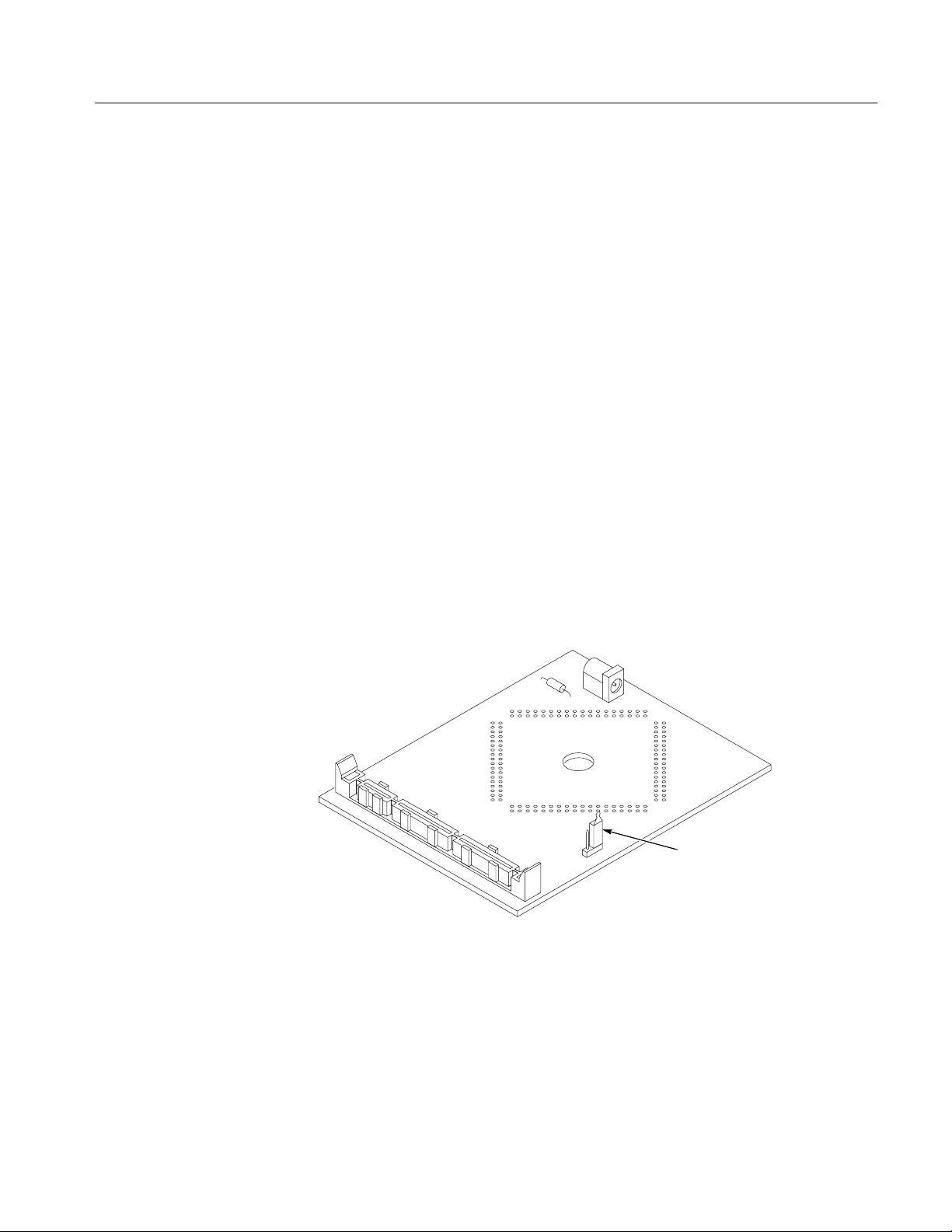
Configuring the Probe Adapter
There is one jumper on the probe adapter to select between multiplexed and
demultiplexed address mode.
Getting Started
Figure 1–1 shows the MUX/DEMUX jumper location on the probe adapter.
MUX/DEMUX
Jumper
Figure 1–1: Jumper locations on the probe adapter
TMS 600 SAB-C167 80C167 Microcontroller Support Instruction Manual
1–3
Getting Started
Connecting to a System Under Test
Before you connect to the SUT, you must connect the probes to the module.
Your SUT must also have a minimum amount of clear space surrounding the
microcontroller to accommodate the probe adapter. Refer to the Specifications
chapter in this manual for the required clearances.
The channel and clock probes shown in this chapter are for a 102/136-channel
module. The probes will look different if you are using a 96-channel module.
The general requirements and restrictions of microcontroller supports in the
information on basic operations shows the vertical dimensions of a channel or
clock probe connected to square pins on a circuit board.
With a PQFP Probe
Adapter
To connect the logic analyzer to a SUT using a PQFP probe adapter, follow these
steps:
1. Turn off power to your SUT. It is not necessary to turn off the logic analyzer.
CAUTION. Static discharge can damage the microcontroller, the probe adapter,
the probes, or the module. To prevent static damage, handle all the above only in
a static-free environment.
Always wear a grounding wrist strap or similar device while handling the
microcontroller and probe adapter.
2. To discharge your stored static electricity, touch the ground connector located
on the back of the logic analyzer. Then, touch any of the ground pins of the
probe adapter to discharge stored static electricity from the probe adapter.
3. Line up pin 1 on the 144 pin EIAJ QFP test clip, to pin 1 on the connector
located on the bottom of the probe adapter circuit board, as shown in
Figure 1–2.
1–4
TMS 600 SAB-C167 80C167 Microcontroller Support Instruction Manual
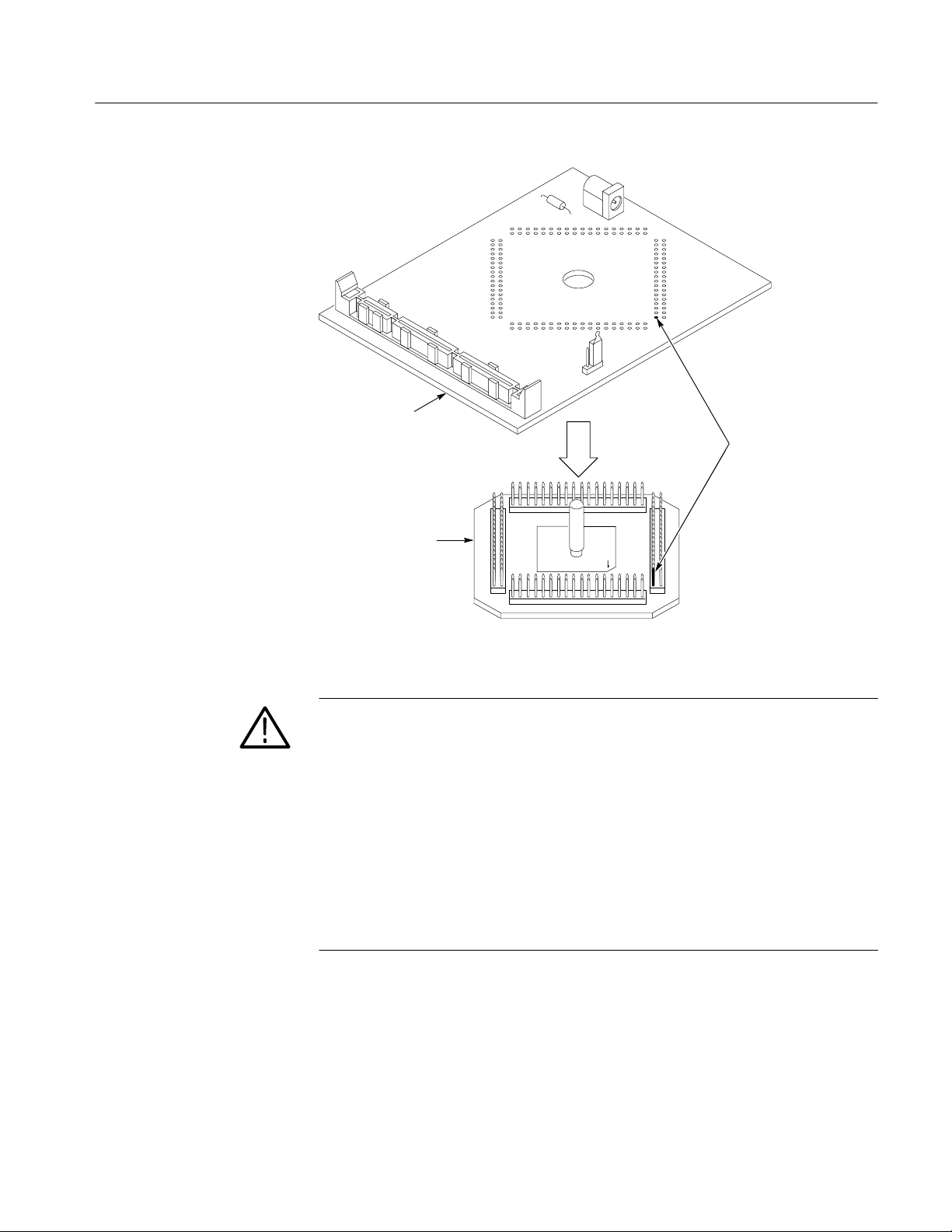
Probe adapter
144 pin EIAJ
QFP test clip
Getting Started
Pin 1
Figure 1–2: Attaching the PQFP clip to the probe adapter.
CAUTION. This EIAJ PQFP (Plastic Quad Flat Pack) probe adapter has been
equipped with a clip that has been designed for tight tolerances.
The clip supports only PQFP devices that conform to the EIAJ standard.
Attaching the clip to a device that does not conform to this EIAJ standard can
easily damage the clip’s connection pins and/or the microcontroller, causing the
probe adapter to malfunction.
Please contact the IC manufacturer to verify that the microcontroller you are
connecting to conforms to the EIAJ standard.
For best performance and long probe life, exercise extreme care when connecting
the probe to the microcontroller.
TMS 600 SAB-C167 80C167 Microcontroller Support Instruction Manual
1–5

Getting Started
4. Place the probe adapter assembly onto the microcontroller on your SUT,
as shown in Figure 1–3.
Probe adapter
assembly
Pin 1
Figure 1–3: Connecting the probe adapter to the SUT.
Microcontroller
Pin 1
1–6
TMS 600 SAB-C167 80C167 Microcontroller Support Instruction Manual
Pin-1 side
Getting Started
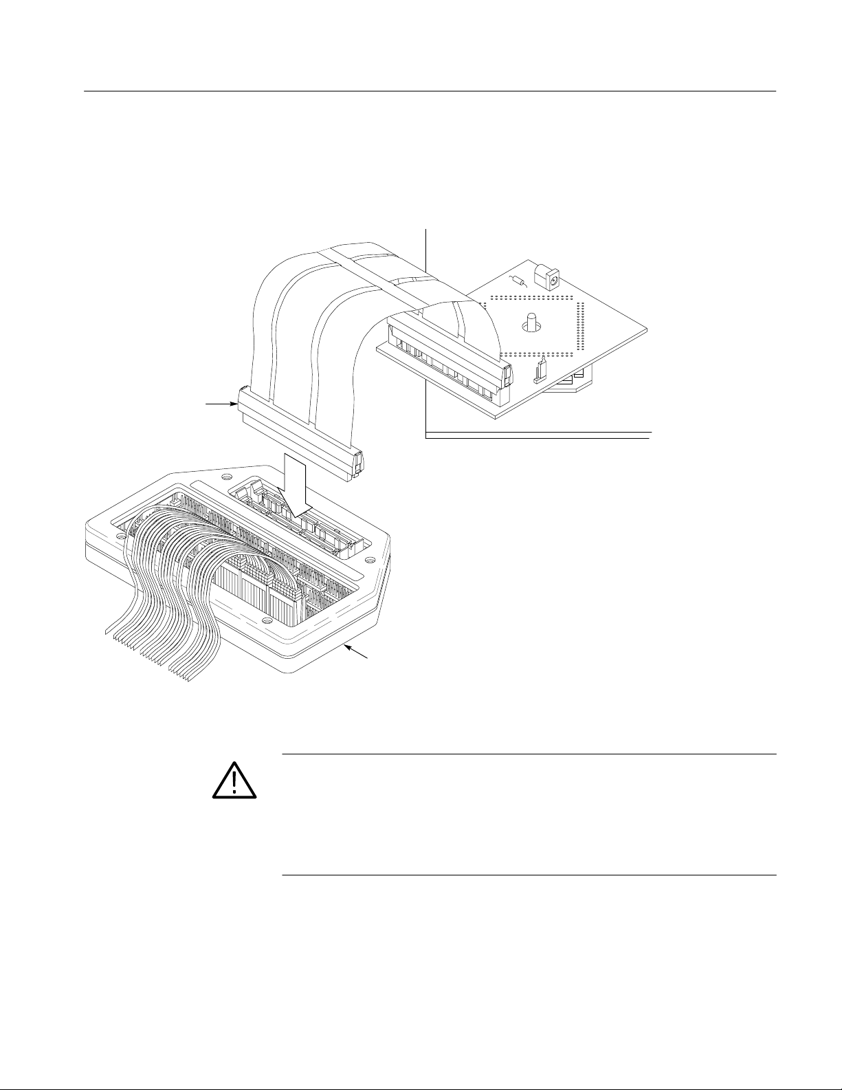
5. Align pin 1 on the LO cable connector, the end on the narrowest cable strip
of the cable, with pin 1 on the LO connector on the high-density probe.
Connect the cable to the connector as shown in Figure 1–4.
High-density probe
Figure 1–4: Connecting the cable to the high-density probe
CAUTION. Failure to correctly place the probe adapter onto the microcontroller
might permanently damage all electrical components when power is applied.
Center the clip on the microcontroller and apply an equal downward force on all
four sides of the clip, slightly rocking the probe adapter in a clockwise circle.
Do not apply leverage to the probe adapter when installing or removing it.
TMS 600 SAB-C167 80C167 Microcontroller Support Instruction Manual
1–7

Getting Started
6. Connect the channel and clock probes to the high-density probe as shown in
Figure 1–5. Match the channel groups and numbers on the probe labels to the
corresponding pins on the high-density probe. Match the ground pins on the
probes to the corresponding pins on the probe adapter.
Clock probe
Hold the channel probes by the podlet
holder when connecting them to the
high-density probe. Do not hold them
by the cables or necks of the podlets.
Channel probe
and podlet holder
Without a Probe Adapter
Channels connect to
the logic analyzer
High-density probe
Figure 1–5: Connecting channel and clock probes to a high-density probe
7. Measure the resistance between Vcc and ground to verify that they are not
shorted together. If you detect a short, determine the source and repair the
problem before applying power.
You can use channel probes, clock probes, and leadsets with a commercial test
clip (or adapter) to make connections between the logic analyzer and your SUT.
To connect the probes to 80C167 signals on the SUT using a test clip, follow
these steps:
1. Turn off power to your SUT. It is not necessary to turn off power to the logic
analyzer.
1–8
TMS 600 SAB-C167 80C167 Microcontroller Support Instruction Manual

Getting Started
CAUTION. Static discharge can damage the microcontroller, the probes, or the
module. To prevent static damage, handle all of the above only in a static-free
environment.
Always wear a grounding wrist strap or similar device while handling the
microcontroller.
2. To discharge your stored static electricity, touch the ground connector located
on the back of the logic analyzer. If you are using a test clip, touch any of the
ground pins on the clip to discharge stored static electricity from it.
3. Use Table 1–2 to connect the channel probes to 80C167 signal pins on the
test clip or in the SUT.
Use leadsets to connect at least one ground lead from each channel probe and
the ground lead from each clock probe to ground pins on your test clip.
T able 1–2: 80C167 signal connections for channel probes
Section:channel 80C167 signal Section:channel 80C167 signal
A3:7 P2.15* D3:7 T2IN*
A3:6 P2.14* D3:6 T3IN*
A3:5 P2.13* D3:5 T4IN*
A3:4 P2.12* D3:4 CAPIN*
A3:3 P2.1 1* D3:3 MRST*
A3:2 P2.10* D3:2 MTSR*
A3:1 P2.9* D3:1 TXD0*
A3:0 P2.8* D3:0 RXD0*
A2:7 A23 D2:7 CC31IO*
A2:6 A22 D2:6 CC30IO*
A2:5 A21 D2:5 CC29IO*
A2:4 A20 D2:4 CC28IO*
A2:3 A19 D2:3 POUT3*
A2:2 A18 D2:2 POUT2*
A2:1 A17 D2:1 POUT1*
A2:0 A16 D2:0 POUT0*
A1:7 A15 D1:7 D15
A1:6 A14 D1:6 D14
A1:5 A13 D1:5 D13
A1:4 A12 D1:4 D12
TMS 600 SAB-C167 80C167 Microcontroller Support Instruction Manual
1–9

Getting Started
T able 1–2: 80C167 signal connections for channel probes (cont.)
Section:channel 80C167 signalSection:channel80C167 signal
A1:3 A1 1 D1:3 D11
A1:2 A10 D1:2 D10
A1:1 A9 D1:1 D9
A1:0 A8 D1:0 D8
A0:7 A7 D0:7 D7
A0:6 A6 D0:6 D6
A0:5 A5 D0:5 D5
A0:4 A4 D0:4 D4
A0:3 A3 D0:3 D3
A0:2 A2 D0:2 D2
A0:1 A1 D0:1 D1
A0:0 A0 D0:0 D0
C3:7 CS4~* C2:7 BHE~
C3:6 CS3~* C2:6 WR~
C3:5 CS2~* C2:5 RD~
C3:4 CS1~* C2:4 ALE
C3:3 CS0~* C2:3 READY~*
C3:2 CLKOUT* C2:2 RSTIN~
C3:1 NMI~* C2:1 HLDA~
C3:0 EA~* C2:0 RSTOUT~
C1:7 P8.7* C0:7 P2.7*
C1:6 P8.6* C0:6 P2.6*
C1:5 P8.5* C0:5 P2.5*
C1:4 P8.4* C0:4 P2.4*
C1:3 P8.3* C0:3 P2.3*
C1:2 P8.2* C0:2 P2.2*
C1:1 P8.1* C0:1 P2.1*
C1:0 P8.0* C0:0 P2.0*
* Signal not required for disassembly.
1–10
TMS 600 SAB-C167 80C167 Microcontroller Support Instruction Manual
Getting Started
Table 1–3 shows the clock probes and the 80C167 signal to which they must
connect for disassembly to be correct.
T able 1–3: 80C167 signal connections for clock probes
Section:channel 80C167 signal
CK:3 BHE~=
CK:2 WR~=
CK:1 RD~=
CK:0 ALE=
= Indicates the channel is double probed
4. Align pin 1 or A1 of your test clip with the corresponding pin 1 or A1 of the
80C167 microcontroller in your SUT and attach the clip.
Applying and Removing Power
A power supply for the TMS 600 80C167 probe adapter is included with the
support. The power supply provides +5 volts power to the probe adapter. The
center connector of the power jack connects to Vcc.
NOTE. Whenever the SUT is powered off, be sure to remove power from the probe
adapter.
To apply power to the 80C167 probe adapter and SUT, follow these steps:
CAUTION. Failure to use the +5 V power supply provided by Tektronix might
permanently damage the probe adapter and 80C167 microcontroller. Do not
mistake another power supply that looks similar for the +5 V power supply.
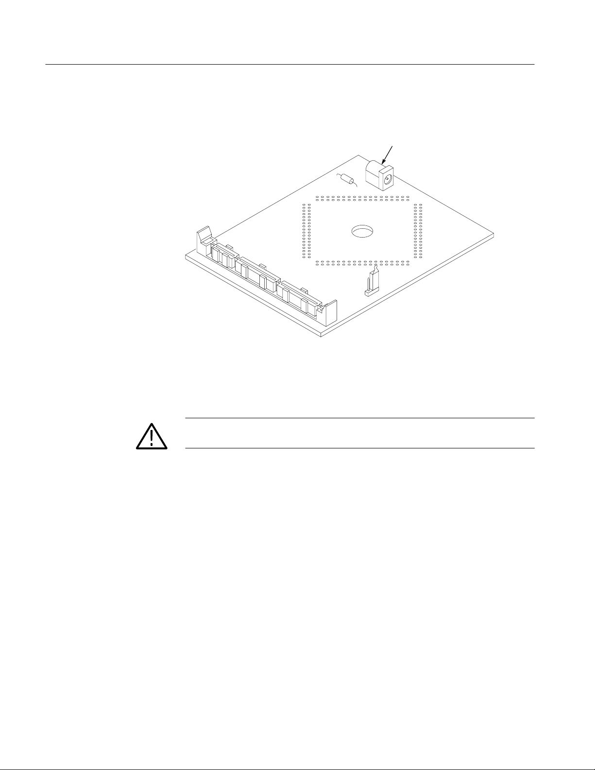
1. Connect the +5 V power supply to the jack on the probe adapter. Figure 1–6
shows the location of the jack on the adapter board.
CAUTION. Failure to apply power to the probe adapter before applying power to
your SUT might permanently damage the 80C167 microcontroller and SUT.
2. Plug the power supply for the probe adapter into an electrical outlet.
3. Power on the SUT.
TMS 600 SAB-C167 80C167 Microcontroller Support Instruction Manual
1–11
Getting Started
Figure 1–6 shows the location of the power jack.
Power jack
Figure 1–6: Location of the power jack
To remove power from the SUT and 80C167 probe adapter, follow these steps:
CAUTION. Failure to power down your SUT before removing the power from the
probe adapter might permanently damage the 80C167 microcontroller and SUT.
1. Power off your SUT.
2. Unplug the power supply for the probe adapter from the electrical outlet.
1–12
TMS 600 SAB-C167 80C167 Microcontroller Support Instruction Manual

Operating Basics
 Loading...