

Page 1
•
•
•
•
•
•
•
•
•
•
•
•
•
•
Instruction Manual
Tektronix
/
TM502A
Power Module
070-6502-01
•
•
•
•
•
•
•
•
•
•
•
•
•
•
•
•
•
Warning
The servicing instructions are for use by qualified
personnel only. To avoid personal injury, do not
perform any servicing unless you are qualified to
do so. Refer to the Safety Summary prior to
performing service.
Please check for change information at the rear
of this manual .
First Printing: January I 993
Revised Printing: December 1993
•
Page 2
•
•
•
Instrument Serial Numbers
Each instrument manufactured by Tektronix has a serial number on a panel insert or tag, or stamped on the
chassis. The first letter in the serial number designates the country of manufacture. The last five digits of the
serial number are assigned sequentially and are unique to each instrument. Those manufactured in the
United States have six unique digits. The country of manufacture is identified as follows:
B010000
E200000
J300000
H700000
Instruments manufactured for Tektronix by external vendors outside the United States are assigned a two digit
alpha code to identify the country of manufacture (e.g., JP for Japan, HK for Hong Kong, IL for Israel, etc.).
Tektronix, Inc., P.O. Box 500, Beaverton, OR 97077
Printed in U.S.A.
Copyright
patents, issued and pending. The following are registered trademarks: TEKTRONIX, TEK, TEKPROBE, and
SCOPE-MOBILE.
© Tektronix, Inc., 1993. All rights reserved. Tektronix products are covered by U.S. and foreign
Tektronix, Inc., Beaverton, Oregon, USA
Tektronix United Kingdom, Ltd., London
Sony/Tektronix, Japan
Tektronix Holland, NV, Heerenveen, The Netherlands
•
•
•
•
•
•
•
•
•
•
•
•
•
•
•
•
•
•
•
•
•
•
•
•
•
•
•
•
•
Page 3
•
•
•
•
•
•
•
•
•
•
•
•
•
•
•
•
WARRANTY
Tektronix warrants that this product will be free from defects in materials and workmanship for a period of one (1) year from the
date of shipment. If any such product proves defective during this warranty period, Tektronix, at its option, either will repair the
defective product without charge for parts and labor, or will provide a replacement in exchange for the defective product.
In order to obtain service under this warranty, Customer must notify Tektronix of the defect before the expiration of the warranty
period and make suitable arrangements for the performance of service. Customer shall be responsible for packaging and
shipping the defective product to the service center designated by Tektronix, with shipping charges prepaid. Tektronix shall
pay for the return of the product to Customer if the shipment is to a location within the country in which the Tektronix service
center is located. Customer shall be responsible for paying all shipping charges, duties, taxes, and any other charges for
products returned to any other locations .
This warranty shall not apply to any defect, failure or damage caused by improper use or improper or inadequate maintenance
and care. Tektronix shall not be obligated to furnish service under this warranty a) to repair damage resulting from attempts by
personnel other than Tektronix representatives to install, repair or service the product; b) to repair damage resulting from
improper use or connection to incompatible equipment; or c) to service a product that has been modified or integrated with
other products when the effect of such modification or integration increases the time or difficulty of servicing the product.
THIS WARRANTY IS GIVEN BY TEKTRONIX WITH RESPECT TO THIS PRODUCT IN LIEU OF ANY OTHER
WARRANTIES, EXPRESSED OR IMPLIED. TEKTRONIX AND ITS VENDORS DISCLAIM ANY IMPLIED WARRANTIES OF
MERCHANTABILITY OR FITNESS FOR A PARTICULAR PURPOSE. TEKTRONIX' RESPONSIBILITY TO REPAIR OR
REPLACE DEFECTIVE PRODUCTS IS THE SOLE AND EXCLUSIVE REMEDY PROVIDED TO THE CUSTOMER FOR
BREACH OF THIS WARRANTY. TEKTRONIX AND ITS VENDORS WILL NOT BE LIABLE FOR ANY INDIRECT, SPECIAL,
INCIDENTAL, OR CONSEQUENTIAL DAMAGES IRRESPECTIVE OF WHETHER TEKTRONIX OR THE VENDOR HAS
ADVANCE NOTICE OF THE POSSIBILITY OF SUCH DAMAGES .
•
•
•
•
•
•
•
•
•
•
•
•
•
•
•
•
Page 4

•
•
•
•
•
•
•
•
•
•
•
•
•
•
•
•
•
•
•
•
•
•
•
•
•
•
•
•
•
•
•
•
Page 5
•
•
•
•
•
•
•
•
•
•
•
•
•
•
•
•
•
•
•
•
Specification
Operating Instructions
Contents
Operators Safety Summary .................................. .
Service Safety Summary .................................... .
Specification ............................................... .
Instrument Description .................................. .
Performance Conditions ................................. .
Operating Instructions ...................................... .
Power Source .......•...................................
Power Usage/ Loading Considerations ................... .
Line Voltage Selection/Fuse Replacement ................ .
Handleffilt Stand Installation ............................ .
Operating Temperature .................................. .
Power Modules .......•..................................
Family Compatibility .••..................................
Module Installation ....•..................................
Plug-in Retainer Clip Information ....................... .
Power-on Procedure .................................. .
iii
V
1-1
1-1
1-1
2-1
2-1
2-1
2-1
2-3
2-4
2-4
2-4
2-4
2-5
2-5
•
•
•
•
•
•
•
•
•
•
•
•
Maintenance
TM 502A Instruction Manual
Maintenance ..........•.....................................
Static Sensitive Components ............................ .
Cleaning ............................................... .
Obtaining Replacement Parts ............................ .
Preventive Maintenance and Calibration .................. .
Soldering Techniques ................................... .
Removing the Cabinet ................................... .
Removing the Circuit Board ............................. .
Removing the Voltage Selector/Fuse Holder Assembly .... .
Replacing the Series Pass Transistor ..................... .
Packaging information .................................. .
3-1
3-1
3-2
3-3
3-3
3-4
3-4
3-4
3-5
3-5
3-6
i
Page 6
•
•
Options
Replaceable Electrical Parts
Diagrams and Circuit Board Illustrations
Symbols ...••...........................................
Component Values ...................................... .
Graphic Items and Special Symbols Used in This Manual .. .
Component Locator Diagrams ........................... .
Replaceable Mechanical Parts
Index
6-1
6-1
6-2
6-2
•
•
•
•
•
•
•
•
•
•
•
•
•
•
•
•
•
•
•
•
•
•
•
•
•
ii
Contents
•
•
•
•
•
Page 7
•
•
•
•
•
•
•
•
•
•
•
•
•
•
•
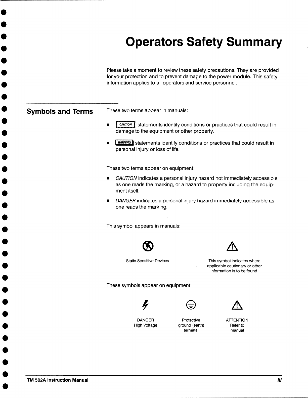
Symbols and Terms
Operators Safety Summary
Please take a moment to review these safety precautions. They are provided
for your protection and to prevent damage to the power module. This safety
information applies to all operators and service personnel.
These two terms appear in manuals:
•
~
damage to the equipment or other property .
• I wARNtNG I statements identify conditions or practices that could result in
personal injury or loss of life .
These two terms appear on equipment:
• CAUTION indicates a personal injury hazard not immediately accessible
as one reads the marking, or a hazard to property including the equipment itself .
statements identify conditions or practices that could result in
•
•
•
•
•
•
•
•
•
•
•
•
•
• DANGER indicates a personal injury hazard immediately accessible as
one reads the marking .
This symbol appears in manuals:
®
Static-Sensitive Devices
These symbols appear on equipment:
DANGER
High Voltage
Protective
ground (earth)
terminal
This symbol indicates where
applicable cautionary or other
information is to be found .
ATTENTION
Refer to
manual
•
•
•
•
TM 502A Instruction Manual
iii
Page 8
•
•
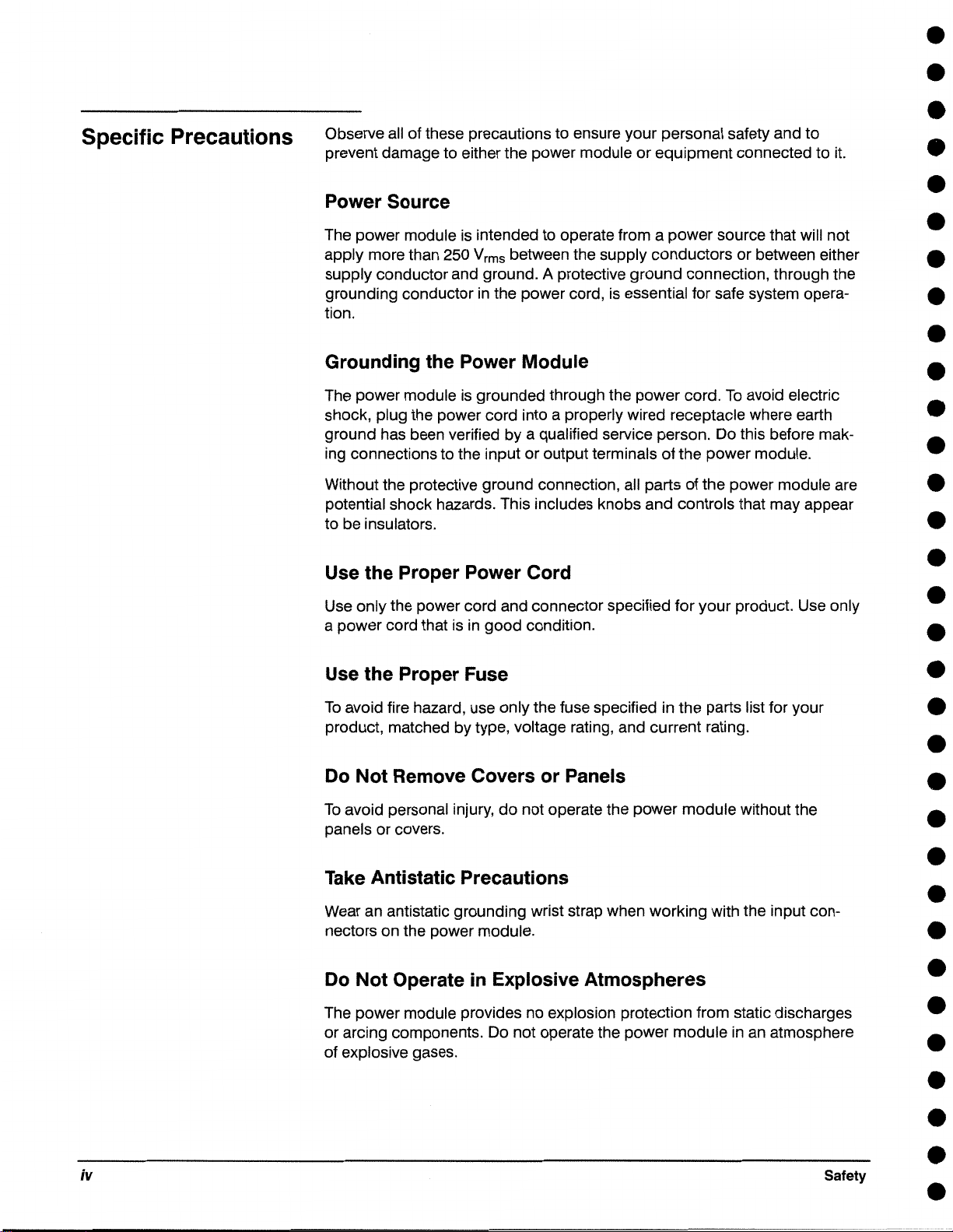
Specific Precautions
Observe all of these precautions to ensure your personal safety and to
prevent damage to either the power module or equipment connected to it.
Power Source
The power module is intended to operate from a power source that will not
apply more than 250
supply conductor and ground. A protective ground connection, through the
grounding conductor in the power cord, is essential for safe system operation.
Grounding the Power Module
The power module is grounded through the power cord. To avoid electric
shock, plug the power cord into a properly wired receptacle where earth
ground has been verified by a qualified service person. Do this before making connections to the input or output terminals of the power module.
Without the protective ground connection, all parts of the power module are
potential shock hazards. This includes knobs and controls that may appear
to be insulators.
Use the Proper Power Cord
Vrms between the supply conductors or between either
•
•
•
•
•
•
•
•
•
•
•
•
•
Use only the power cord and connector specified for your product. Use only
a power cord that is in good condition.
Use the Proper Fuse
To avoid fire hazard, use only the fuse specified in the parts list for your
product, matched by type, voltage rating, and current rating.
Do Not Remove Covers or Panels
To avoid personal injury, do not operate the power module without the
panels or covers.
Take Antistatic Precautions
Wear an antistatic grounding wrist strap when working with the input connectors on the power module.
Do Not Operate in Explosive Atmospheres
The power module provides no explosion protection from static discharges
or arcing components. Do not operate the power module in an atmosphere
of explosive gases.
•
•
•
•
•
•
•
•
•
•
•
•
•
iv
Safety
•
•
•
•
Page 9
•
•
•
•
•
•
•
•
•
•
•
•
•
•
•
•
•
•
•
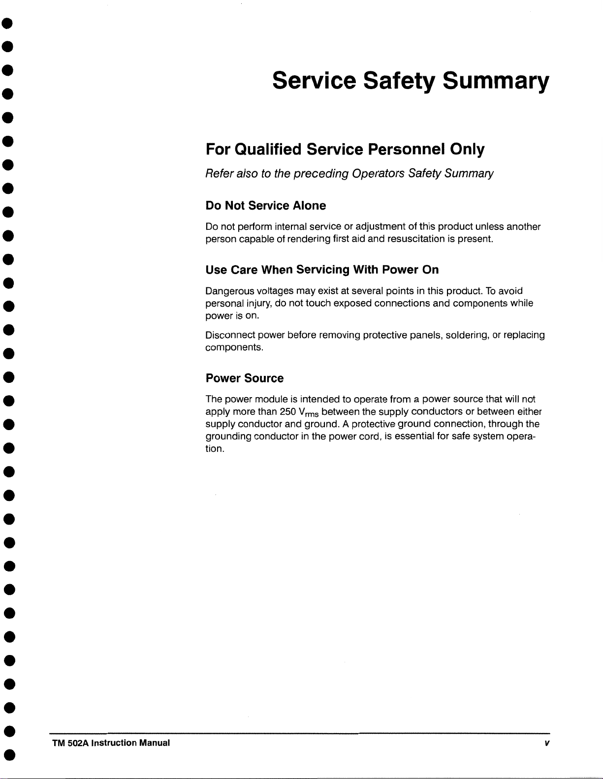
Service Safety Summary
For Qualified Service Personnel Only
Refer also to the preceding Operators Safety Summary
Do Not Service Alone
Do not perform internal service or adjustment of this product unless another
person capable of rendering first aid and resuscitation is present.
Use Care When Servicing With Power On
Dangerous voltages may exist at several points in this product. To avoid
personal injury, do not touch exposed connections and components while
power is on .
Disconnect power before removing protective panels, soldering, or replacing
components .
Power Source
The power module is intended to operate from a power source that will not
apply more than 250
supply conductor and ground. A protective ground connection, through the
grounding conductor in the power cord, is essential for safe system operation .
Vrms between the supply conductors or between either
•
•
•
•
•
•
•
•
•
•
•
•
•
TM 502A Instruction Manual
V
Page 10

•
•
•
•
•
•
•
•
•
•
•
•
•
•
•
•
•
•
•
•
•
•
•
•
•
•
vi
Safety
•
•
•
•
•
•
Page 11
•
•
•
•
•
•
•
•
•
•
•
•
•
•
•
Instrument
Description
Performance
Conditions
Specification
The TM 502A is a two compartment-wide power module for the
TM 500-series of modular instrumentation. The power module accepts up to
two independently functional plug-in modules to form a compact, versatile,
and low-cost instrumentation system. The TM 502A is a basic power source
for plug-in modules of the TM 500 series family. It provides unregulated de
and ac supplies and nondedicated power transistors for plug-in usage .
The values listed in this section are valid only when the instrument is
operated at an ambient temperature between
0°c and +so0c.
•
•
•
•
•
•
•
•
•
•
•
•
•
•
•
•
•
TM 502A Instruction Manual
1-1
Page 12
•
•
Characteristics
+33.5 VDC
Tolerance
PARDb
Maximum load
Maximum load
-33.5 VDC
Tolerance
PARDb
Maximum load
Maximum load
+11.5 VDC
Tolerance
Maximum load
8
8
8
~i
~i
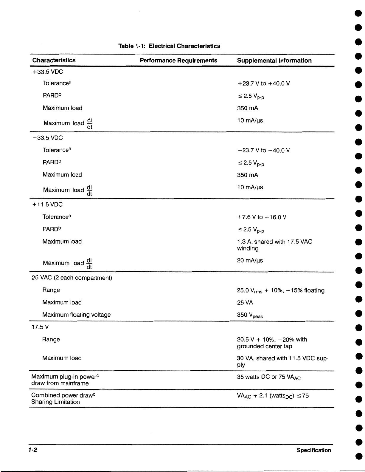
Table 1-1 : Electrical Characteristics
Performance Requirements
Supplemental Information
+23.7 V to +40.0 V
::52.5 Vp-p
350mA
10 mA/µs
-23.7 V to -40.0 V
::52.5 Vp-p
350mA
10 mA/µs
+7.6 V to +16.0 V
::52.5 Vp-p
1 .3 A, shared with 17 .5 VAC
winding
•
•
•
•
•
•
•
•
•
•
•
•
•
•
•
Maximum load
25 VAC (2 each compartment)
Range
Maximum load
Maximum floating voltage
17.5 V
Range
Maximum load
Maximum plug-in power
draw from mainframe
Combined power drawc
Sharing Limitation
~!
0
20 mA/µs
25.0 Vrms + 10%, -15% floating
25VA
350 Vpeak
20.5 V + 10%, -20% with
grounded center tap
30 VA, shared with 11.5 VDC supply
35 watts DC or 75 VAAc
VAAc + 2.1 (wattsoc)
:s; 75
•
•
•
•
•
•
•
•
•
•
•
•
1-2
Specification
•
•
•
Page 13

•
•
•
•
•
•
•
•
•
•
•
•
•
•
Table 1-1: Electrical Characteristics (Cont.)
Characteristics
Total Power from Mainframe
Total power drawc
(all compartments combined)
Series Pass Transistors
Type
Maximum dissipation
Source Power Requirements
Voltage Ranges
Line Frequency
Maximum Power Consumption
Fuse Data
Performance Requirements
Supplemental Information
VAAc + 2.1 (watts
One NPN and PNP per compart-
ment
7.5 W each, 15 W total
Selectable:
100 V, 120 V, 220 V, and 240 V
nominal line
50/60 Hz
Approximately 120 W
0
± 10%
c) :s; 75
•
•
•
•
•
•
•
•
•
•
•
•
•
100 V, 120 V ranges
220 V, 240 V ranges
Miscellaneous
Maximum recommended plug-in
power dissipation
One-wide
Two-wide
Recommended adjustment interval
8
Worst case: Low line with full load and high line with no load. These limits Include PARO .
hPeriodic and Random Deviation. See National Electrical Manufacturers Association (NEMA) Standards Publication No. PY1-1972.
CAt nominal line voltage .
1.0 A, 3 AG, slow blow, 250 V
0.5 A, 3 AG, slow blow, 250 V
10 to15 W
25to 35 W
1000 hours or 6 months
•
•
•
•
•
TM 502A Instruction Manual
REV DEC 1993
1-3
Page 14

Table 1-2: Environmental Characteristics
•
•
8
•
Characteristics
Temperature
Operating
Non-operating
Humidityb
Altitude
Operating
Non-operating
Vibration
Shock
Bench Handling
Transportation
EMC
Description
Meets MIL-T-28800D, class 5.
0°c to +50°C
-55°C to + 75°C
95% RH, 0°C to 30°C
non-condensing
15,000 ft (4.6 km)
50,000 ft (15 km)
O" (0.25 mm) peak-to-peak,
0.01
5 Hz to 55 Hz, 75 minutes
20 g's (1/2 sine)
11 ms duration, 3 shocks in each
direction along 3 major axes,
18 total shocks
12 drops from 45°
4" or equilibrium, whichever
occurs first.
Qualified under National Safe Transit Association Preshipment Test
Procedures 1A-B-1 and 1A-B-2
Electro-mechanical compatibility within limits of F.C.C. Regulations,
Part 15, Subpart J, Class
A.
Exceeds MIL-T-28800D, class 5.
Exceeds MIL-T-28800D, class 5.
Meets MIL-T-28800D, class 5 without plug-ins (0.015"
displacement, 30 g's shock).
Meets MIL-T-28800D, class 5 with-
out plug-ins (0.015"
displacement, 30 g's shock)
Meets MIL-T-28800D, class 5.
•
•
•
•
•
•
•
•
•
•
•
•
•
•
•
•
Electrical Discharge
awith plug-ins
1-4
20 kV maximum charge applied to instrument case.
Specification
•
•
•
•
•
•
•
•
•
•
•
•
•
Page 15
•
•
•
•
•
•
•
•
•
•
•
•
•
•
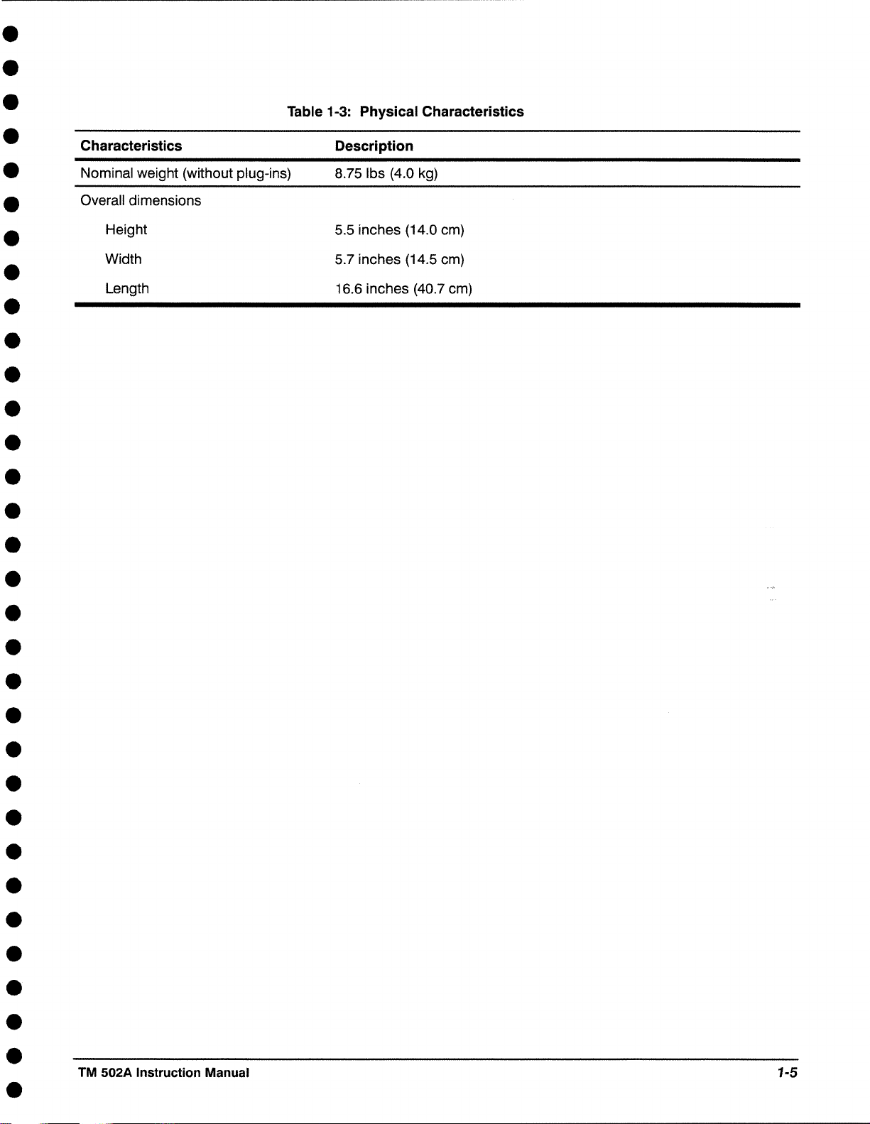
Characteristics
Nominal weight (without plug-ins)
Overall dimensions
Height
Width
Length
Table 1-3: Physical Characteristics
Description
8.75 lbs (4.0 kg)
5.5 inches (14.0 cm)
5.7 inches (14.5 cm)
16.6 inches (40.7 cm)
•
•
•
•
•
•
•
•
•
•
•
•
•
•
•
•
•
•
TM 502A Instruction Manual
1-5
Page 16

•
•
•
•
•
•
•
•
•
•
•
•
•
•
•
•
•
•
•
•
•
•
•
•
•
•
1-6
Specification
•
•
•
•
•
•
Page 17
•
•
•
•
•
•
•
•
•
•
•
•
•
•
•
•
•
•
•
•
Power Source
Power Usage/
Loading
Considerations
Operating Instructions
This section of the manual tells how to prepare the power module for use,
and install plug-in modules .
The TM 502A Power Module is calibrated and ready for use when received.
A list of standard accessories (and part numbers) is located in the back of
this manual.
The TM 502A Power Module is designed to operate from a power source
with its neutral at or near earth (ground) potential with a separate safetyearth conductor. It is not intended to operate from two phases of a multi-
phase system .
With two plug-in modules installed, the TM 502A Power Module can require
up to 120 W of power at the upper limits of the high-line voltage ranges .
Actual power consumption depends on the particular module combination
and operating mode selected at any one time .
The power capability of the TM 502A Power Module can best be used by
carefully planning the plug-in configuration, the external loads, and the
resulting power distributions. The power module will work best if you do the
following:
1. Use equal loads in both compartments .
2. Dissipate as much power as possible in the external loads.
3. Operate the system in an ambient temperature near 25°C .
•
•
•
•
•
•
•
•
•
•
•
•
Line Voltage
Selection/Fuse
Replacement
TM 502A Instruction Manual
Each plug-in has access to a pair of heat-sinked, series-pass transistors-
one NPN and the other PNP. These transistors enable the plug-in to operate
in power ranges not possible if the power were to dissipate within the plugins .
The line voltage selector is part of the line cord plug assembly, located in the
rear of the power module. Verify that the voltage shown in the selector
window is correct for the line voltage available.
If the displayed voltage selection is incorrect, or the fuse needs replacement, perform the following procedure while referring to Figure 2-1 .
1. Ensure that the power switch on the rear of the module is turned off and
that the line cord is not plugged into the line voltage connector .
REV DEC 1993
2-1
Page 18
•
•
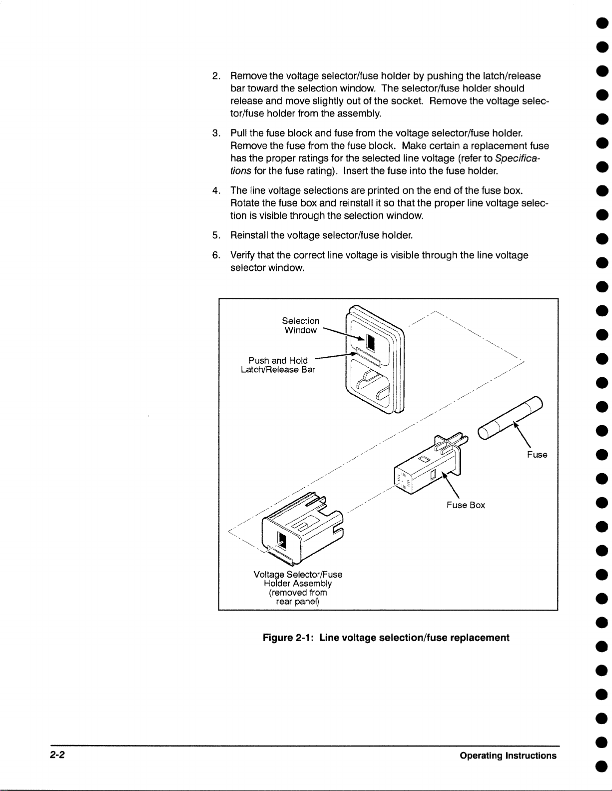
2. Remove the voltage selector/fuse holder by pushing the latch/release
bar toward the selection window. The selector/fuse holder should
release and move slightly out of the socket. Remove the voltage selec-
tor/fuse holder from the assembly.
3. Pull the fuse block and fuse from the voltage selector/fuse holder.
Remove the fuse from the fuse block. Make certain a replacement fuse
has the proper ratings for the selected line voltage (refer to Specifica-
tions for the fuse rating). Insert the fuse into the fuse holder.
4. The line voltage selections are printed on the end of the fuse box.
Rotate the fuse box and reinstall it so that the proper line voltage selec-
tion is visible through the selection window.
5. Reinstall the voltage selector/fuse holder.
6. Verify that the correct line voltage is visible through the line voltage
selector window.
Push and Hold
Latch/Release Bar
•
•
•
•
•
•
•
•
•
•
•
•
•
/
/
/
/
/
/
Fuse Box
Voltage Selector/Fuse
Holder Assembly
(removed from
rear panel)
Figure 2-1: Line voltage selection/fuse replacement
•
•
•
Fuse
•
•
•
•
•
•
•
•
•
•
2-2
Operating Instructions
•
•
•
•
Page 19

•
•
•
•
•
•
•
•
•
•
•
•
•
•
•
Handle/Tilt Stand
Installation
Before you install the handle, check the handle kit contents against the
following list:
Phillips screws
2
metal washers
2
lock washers
2
plastic locking buttons
2
1 metal handle
A Phillips screwdriver is the only tool required.
Perform the following steps to install the handle/tilt stand .
1. Turn off the power switch and disconnect the line cord .
•
•
•
•
•
•
•
•
•
•
•
•
•
•
/
Figure 2-2: Handle installation
2. Remove any plug-in modules .
3. On each side of the power module (approximately 2 inches (5 cm) from
the front edge) is a black plug. Remove each plug by pushing it out
from the inside of the power module.
4. From outside of the power module, place the plastic locking button in
the handle slot and into the square hole in the side panel, as shown in
Figure 2-2. Note that the rounded edges of the button must face the top
and bottom panels of the power module as shown in the illustration .
•
•
•
TM 502A Instruction Manual
2-3
Page 20

Operating
Temperature
5. Place the metal washer inside the side panel over the hole in the button.
6. Install and tighten the Phillips screw.
Repeat the procedure for the other end of the handle.
The TM 502A Power Module can operate in an ambient air temperature
range of o·c to +so·c (32°F to +122°F). Since the TM 502A Power
Module can be stored in temperatures between -ss·c and +75°C (-67°F
+ 167°F), allow the instrument chassis to return to within the temperature
to
operating limits before applying power.
•
•
•
•
•
•
•
•
•
•
Power Modules
Family Compatibility
It is not necessary to use both plug-in compartments to operate the power
module.
Turn the power module off before inserting or removing the plug-in;
otherwise, damage can occur to the plug-in circuitry.
Mechanically, the TM 500-series plug-in modules are very similar to other
Tektronix product families. However, they are not
Therefore, the TM 502A interface has barriers on the mating connectors
between pins 6 and 7 to ensure that incompatible plug-ins cannot be in-
serted. (Pin 1 is on the connector end near the bottom side of the power
module.) A compatible module will have a matching slot between pins 6
and 7 of its main circuit board edge connector. This slot and barrier com-
bination is the primary keying assignment.
electrically compatible.
•
•
•
•
•
•
•
•
•
•
•
•
•
Module Installation
2-4
The modularity of this instrumentation system provides for a host of functions to be performed by the plug-in modules. Specific functions are
grouped into families of classes, of which there may be several plug-in
module members. For example, some classes are power supplies, signal
sources, measurement, and so forth. Each modular member of a functional
family will have a second slot peculiar to its family assignment located in its
edge connector. The TM 502A can "program" one or both compartments to
accept only members of that family by installing a second barrier in the
interface connector to match the module's slot location. Contact the nearest
Tektronix field office to order additional barriers.
Operating Instructions
•
•
•
•
•
•
•
•
•
Page 21

•
•
•
Perform the following steps to install a module in the TM 502A Power
Module .
•
•
•
•
•
•
•
•
•
•
•
•
•
•
•
•
1 . Check the location of the plastic barriers on the TM 502A interconnect-
ing jack to ensure that their locations match the slots in the edge of the
plug-in module's main circuit board. If they do not match, refer the
qualified service personnel to the Maintenance section of this manual for
more information .
2. Align the plug-in module chassis with the upper and lower guides of the
selected compartment. Push the module in and press firmly to seat the
circuit board in the interconnecting jack. (Remove the plug-in module
by pulling on the release latch in the lower left corner of the plug-in
module.)
Plug-in Retainer Clip Information
The retainer clip is used to ensure that an installed plug-in module can not
come out of the power module while it is moved or transported. Note that
plug-in modules cannot be removed or inserted with the retainer clip
installed .
1. Perform the following steps to install the retainer clip:
2. Stand the power module on end.
3. Remove the round-head Phillips screw located on the bottom side of the
TM 502A Power Module just behind the front casting .
4. Align the hole in the retainer clip with the following: the chassis hole, the
clip extending forward and into the module opening, and the bottom
edge of the plug-in module(s) .
5. Reinstall the screw .
•
•
•
•
•
•
•
•
•
•
•
•
TM 502A Instruction Manual
Power-on Procedure
After completing the power module preparation and plug-in module installation instructions, install the power cord and connect the power cord to the
proper power outlet. Turn on the power switch on the rear of the power
module. Some plug-ins have independent power switches, usually labeled
"OUTPUT," that control power from the mainframe power to the plug-in .
2-5
•
Page 22

•
•
•
•
•
•
•
•
•
•
•
•
•
•
•
•
•
•
•
•
•
•
•
•
•
•
2-6
Operating Instructions
•
•
•
•
•
•
Page 23

•
•
•
•
•
•
•
•
•
•
•
•
•
•
•
•
•
•
•
•
•
•
•
WARNING I
The following servicing instructions are for use only by qualified
personnel.
other than that contained in the operating instructions unless you
are qualified to do so. Refer to the Operator's Safety Summary and
the Service Safety Summary prior
To avoid personal injury, do not perform any servicing
to performing any service .
•
•
•
•
•
•
•
•
•
Page 24

Page 25

•
•
•
•
•
•
•
•
•
•
•
•
•
•
•
Static Sensitive
Components
Maintenance
This section provides maintenance and service information for the TM 502A
power module .
Static discharge can damage any semiconductor component in this
instrument .
This instrument contains electrical components that are susceptible to
damage from static discharge. See Table
various classes of semiconductors. Static voltages of
common in unprotected environments .
Table 3-1 : Relative Susceptibility to Static Discharge Damage
3-1 for relative susceptibility of
1 kV to 30 kV are
•
•
•
•
•
•
•
•
•
•
•
•
•
•
Semiconductor Classes
MOS or CMOS microcircuits, or discrete or linear
microcircuits with MOS inputs (Most Sensitive)
ECL
Schottky signal diodes
Schottky TTL
High-frequency bipolar transistors
JFETs
Linear microcircuits
Low-power Schottky TTL
TTL (Least Sensitive)
8
Voltage equivalent for levels:
1 = 100 to 500 V
2
= 200to500V
3
= 250V
(Voltage discharged from a 100 pF capacitor through a resistance of 100
4=500V
5
= 400to600V
6
= 600to800V
7
= 400 to 1000 V (est.)
8
= 900V
9
= 1200V
Relative
Susceptibility
Levelsa
1
2
3
4
5
6
7
8
9
Q) •
•
•
•
TM 502A Instruction Manual
3-1
Page 26

•
•
Observe the following precautions to avoid damage:
1. Minimize handling of static-sensitive components.
2. Transport and store static-sensitive components or assemblies in their
original containers, on a metal rail, or on conductive foam. Label any
package that contains static-sensitive assemblies or components.
3. Discharge the static voltage from your body by wearing a wrist strap
while handling these components. Servicing static-sensitive assemblies
or components should be performed only at a static-free work station by
qualified service personnel.
4. Nothing capable of generating or holding a static charge should be
allowed on the work station surface.
5. Keep the component leads shorted together whenever possible.
6. Pick up components by the body, never by the leads.
7. Do not slide the components over any surface.
8. Avoid handling components in areas that have a floor or work surface
covering capable of generating a static charge.
9. Use a soldering iron that is connected to earth ground.
10. Use only special antistatic suction type or wick type desoldering tools.
•
•
•
•
•
•
•
•
•
•
•
•
•
Cleaning
This instrument should be cleaned as often as operating conditions require.
Loose dust accumulated on the outside of the instrument can be removed
with a soft cloth or small brush. Remove dirt that remains with a soft cloth
dampened in a mild detergent and water solution. Do not use abrasive
cleaners.
The best way to clean the interior is to blow off the accumulated dust with
dry, low-velocity air (approximately 5 lb/in
dampened with a mild detergent and water solution.
Circuit boards and components must be dry before applying power.
Avoid using chemical cleaning agents which can damage plastic
parts. Avoid chemicals containing benzene, toluene, zylene, acetone, or similar solvents.
2
)
or use a soft brush or cloth
•
•
•
•
•
•
•
•
•
•
•
•
•
3-2
Maintenance
•
•
•
•
Page 27

•
•
•
•
•
•
•
•
•
•
•
•
•
•
•
•
Obtaining
Replacement Parts
Electrical and mechanical parts can be obtained through your local Tektronix
field office or representative. However, it may be possible to obtain many of
the standard electronic components from a local commercial source. Before
purchasing or ordering a part from a source other than Tektronix, Inc., check
the Replaceable Electrical Parts List for the proper value, rating, tolerance,
and description .
NOTE
When selecting replacement parts, remember that the physical size
and shape of
ment.
Some parts are manufactured or selected by Tektronix, Inc., to satisfy particular requirements or are manufactured for Tektronix, Inc., to our specifica-
tions. Most of the mechanical parts used in this instrument have been
manufactured by Tektronix. To determine the manufacturer, refer to the
Replaceable Parts List and the Cross Reference index, Mfr. Code Number to
Manufacturer .
When ordering replacement parts from Tektronix, include the following
information:
1. Instrument type and option number.
2. Instrument serial number .
a component may affect its performance in the instru-
•
•
•
•
•
•
•
•
•
•
•
•
•
Preventive
Maintenance and
Calibration
3. A description of the part (if electrical, include complete circuit number) .
4. Tektronix part number .
The TM 502A power module does not require preventive maintenance or
calibration.
WARNING I
Dangerous voltages exist at several points throughout the power
module.
removed, do not touch exposed connections or components.
Some transistors have voltages present on their cases. Disconnect
power before removing the cabinet and cleaning or replacing parts .
If you must operate the power module with the covers
•
•
•
TM 502A Instruction Manual
3-3
Page 28

•
•
Soldering Techniques
WARNING I
To avoid electric-shock hazard, disconnect the instrument from the
power source before soldering.
The reliability and accuracy of this instrument can be maintained only if
proper soldering techniques are used when repairing or replacing parts.
General soldering techniques which apply to maintenance of any precision
electronic equipment should be used when working on this instrument. Use
only 60/40 rosin-core, electronic grade solder. The choice of soldering iron is
determined by the repair to be made.
When soldering on circuit boards or small wiring, use only a 15 watt, pencil
type soldering iron. A higher wattage soldering iron can cause the etched
circuit wiring to separate from the board base material and melt the insulation from small wiring. Always keep the soldering iron tip properly tinned to
ensure the best heat transfer to the solder joint. Apply only enough heat to
remove the component or to make a good solder joint. To protect heat
sensitive components, hold the component lead with a pair of long-nose
pliers between the component body and the solder joint. Use a solder
removing wick to remove excess solder from connections or to clean circuit
board pads.
•
•
•
•
•
•
•
•
•
•
•
•
•
•
Removing the
Cabinet
Removing the
Circuit Board
•
Before removing the cabinet, turn the power switch off and disconnect the
power cord. Remove any plug-in modules and the handle assembly.
Use the following steps to remove the cabinet:
1 . Remove the two screws on the side and one screw on the bottom
holding the cabinet to the TM 502A front casting.
2. Remove the four screws on the bottom and one screw on the back
holding the power supply to the cabinet.
3. Slide the power supply assembly out through the front of the cabinet.
•
•
•
•
•
•
4. Reinstall the cabinet to remove any shock hazards and to protect the
interior from dust.
•
•
Use the following procedure to remove the circuit board from the TM 502A
power module.
1. Remove the power supply assembly from the power module. Refer to e
Removing the Cabinet earlier in this section for instructions on removing
the cabinet. •
•
•
3-4
Maintenance
•
•
•
Page 29

•
•
•
2. On the power supply assembly, remove the screws on each side that
secure the series-pass transistor clamp; remove the clamp .
•
•
•
•
•
•
•
•
•
•
•
•
•
Removing the Voltage
Selector/Fuse Holder
Assembly
3. Remove the four screws on the interface connector side of the power
supply assembly that secure the circuit board to the chassis.
4. Disconnect the two connectors going to the transformer from the circuit
board .
5. Slide the circuit board out of the power supply assembly .
Use the following procedure to remove the voltage selector/fuse holder
assembly.
1. Remove the cabinet and the circuit board. Refer to
and Removing the Circuit Board earlier in this section .
net
2. Disconnect the connectors from the terminals on the back of the voltage
selector/fuse holder assembly and label each wire .
Do not apply excessive force to the locking tabs. Excessive pressure will break or reduce the strength of the plastic .
Removing the Cabi-
•
•
•
•
•
•
•
•
•
•
•
•
•
Replacing the Series
Pass Transistor
3. The assembly has a locking tab on two sides that secure it in the chas-
sis hole. Push one tab in carefully, pulling gently on the assembly from
the outside, until the side releases.
4. Repeat the previous step to release the other side .
5. Pull the assembly through the chassis hole to the outside while taking
care not to damage the capacitors .
Use the following procedure to replace the series pass transistor.
NOTE
You must apply a new adhesive insulator plate to the transistor
before installing it. Do not use the insulating plate from the old
transistor to maintain the proper insulating characteristics .
1 . If you have not already done so, remove the cabinet and the circuit
board as described earlier in this section.
2. Unsolder and remove the transistor from the circuit board .
•
•
•
TM 502A Instruction Manual
3-5
Page 30

•
•
3. Carefully bend the new transistor leads according to the dimensions in
Figure 3-1. The illustration shows the actual size of the leads so that you
can physically compare the lead angles.
r
0.370"1
'( I
I
i,(0.318~:
Correct transistor lead angles.
Figure 3-1: Series pass transistor replacement (actual size)
4. Apply the new adhesive insulator plate to the transistor side with the
exposed metal.
Correct relationship to circuit board.
•
•
•
•
•
•
•
•
•
•
•
•
Packaging
information
5. Reinstall the circuit board into the power supply assembly.
6. Insert the leads of the replacement transistor into the circuit board holes
with the insulating plate facing the metal chassis.
7. Reinstall the transistor clamp.
8. Solder the transistor onto the board while applying minimum heat with
the soldering iron.
9. Reinstall the assembly into the power module cabinet.
10. Reinstall the power module handle assembly.
A list of standard accessories and part numbers is located at the end of the
Replaceable Mechanical Parts list.
If the TM 502A power module is to be shipped to a Tektronix service center
for service or repair, attach a tag showing the name and address of the
owner and the name of an individual at your firm that can be contacted.
Include the complete instrument serial number and a description of the
required service.
Save and use the packaging in which your instrument was originally •
shipped. If the original packaging is unfit for use or is not available, repack- •
age the instrument using the following steps:
•
•
•
•
•
•
•
•
•
•
•
•
3-6
1. Surround the instrument with polyethylene sheeting to protect the finish
of the instrument.
Maintenance
e
•
•
•
Page 31

•
•
•
•
•
•
•
•
•
•
•
•
•
•
2. Obtain a carton of corrugated cardboard of the correct carton strength
(275 pounds per square inch) with the inside dimensions of no less than
six inches more than the instrument dimensions .
3. Cushion the instrument by tightly packing three inches of dunnage or
urethrane foam between the carton and the instrument on all sides .
4. Seal the carton with shipping tape or an industrial stapler .
•
•
•
•
•
•
•
•
•
•
•
•
•
•
•
•
•
•
TM 502A Instruction Manual
3-7
Page 32

•
•
•
•
•
•
•
•
•
•
•
•
•
•
•
•
•
•
•
•
•
•
•
•
•
•
3-8
Maintenance
•
•
•
•
•
•
Page 33

•
•
•
•
•
•
•
•
•
•
•
•
•
•
•
Options
The following options are available for the TM 502A Power Module .
Option 11-deletes handle/tilt stand
Option 13-adds storage plug-in
Option A 1 -changes the power to Universal European (230 V, 10 A, 50 Hz)
Option A2-changes the power to United Kingdom (230 V, 10 A, 50 Hz)
Option A3-changes the power to Austrialian (230 V, 10 A, 50 Hz)
Option A4-changes the power to North American (230 V, 1
Option AS-changes the power to Switzerland (230 V, 1
O A, 60 Hz)
O A, 50 Hz)
•
•
•
•
•
•
•
•
•
•
•
•
•
•
•
•
•
TM 502A Instruction Manual
4-1
Page 34

•
•
•
•
•
•
•
•
•
•
•
•
•
•
•
•
•
•
•
•
•
•
•
•
•
•
4-2
Options
•
•
•
•
•
•
Page 35

•
•
•
•
•
•
•
•
•
•
•
•
•
•
•
•
Parts Ordering
Information
List of Assemblies
Replaceable Electrical Parts
Replacement parts are available from or through your local Tektronix, Inc.
field office or representative .
When ordering parts, include the following information in your order: part
number, instrument type or number, serial number, and modification number
if applicable .
If a part you have ordered has been replaced with a new or improved part,
your local Tektronix, Inc. field office or representative will contact you concerning any change in part number .
Change information, if any, is located at the rear of this manual.
A list of assemblies can be found at the beginning of the electrical parts list.
The assemblies are listed in numerical order. When the complete compo-
nent number of a part is known, this list will identify the assembly in which
the part is located .
•
•
•
•
•
•
•
•
•
•
•
•
•
Cross Index-Mfr .
Code Number to
Manufacturer
Abbreviations
Component Number
(column 1 of the parts list)
The Mfg. Code Number to Manufacturer Cross Index for the electrical parts
list is located immediately after this page. The cross index provides codes,
names, and addresses of manufacturers of components listed in the electri-
cal parts list.
Abbreviations conform to American National Standard Y1 .1.
Example a. component number
A23R1234 A23 R1234
Assembly number///
Read: Resistor 1234 of Assembly 23
Example b.
A23A2R1234 A23 A2 R1234 Circuit
Assembly numbe~ / Subassembly number ~-number
Read: Resistor 1234 of Subassembly 2 of Assembly 23
~
-~~
Circuit number
component number
/ / ,_
--------
•
•
•
TM 502A Instruction Manual
5-1
Page 36

The circuit component's number appears on the diagrams and circuit board
illustrations. Each diagram and circuit board illustration is clearly marked
with the assembly number. Assembly numbers are also marked on the
mechanical exploded views located in the mechanical parts list. The component number is obtained by adding the assembly number prefix to the circuit
number.
The electrical parts list is divided and arranged by assemblies in numerical
sequence (e.g., assembly A1 with its subassemblies and parts, precedes
assembly A2 with its subassemblies and parts).
•
•
•
•
•
•
•
Tektronix Part No.
(column 2 of the parts list)
Serial No.
(columns 3 & 4 of the parts list)
Name & Description
(column five of the parts list)
Chassis-mounted parts have no assembly number prefix and are located at
the end of the electrical parts list.
Indicates part number to be used when ordering replacement part from
Tektronix.
Column three (3) indicates the serial number at which the part was first
used. Column four (4) indicates the serial number at which the part was
removed. No serial number entered indicates part is good for all serial
numbers.
In the parts list, an item name is separated from the description by a
colon(:). Because of space limitations, an item name may sometimes appear as incomplete. For further item name identification, the U.S. Federal
Catalog handbook H6-1 can be utilized where possible.
•
•
•
•
•
•
•
•
•
•
•
•
•
Mfr. Code
(column 6 of the parts list)
Mfr. Part No.
(column 7 of the parts list)
5-2
Indicates the code number of the actual manufacturer of the part. (Code to
name and address cross reference can be found immediately after this
page.)
Indicates actual manufacturer's part number.
Replaceable Electrical Parts
•
•
•
•
•
•
•
•
•
•
•
•
Page 37

•
•
•
•
•
•
•
•
•
•
•
•
•
•
•
•
•
•
•
•
•
CROSS INDEX - MFR. CODE NUMBER TO MANUFACTURER
Mfr .
Code
S3629 SCHURTER AG H 2015 SECOND STREET
TK1727 PHILIPS NEDERLAND BV POSTBUS 90050
TK1997 COLUMBIA GORGE CENTER 2940 THOMPSEN RD
0J7N9 MCXINC 30608 SAN ANTONIO ST
03508
04222
04713
14936
18796 MURATA ERIE NORTH AMERICAN INC 1900 W COLLEGE AVE
24165 SPRAGUE ELECTRIC CO 267 LOWELL ROAD
26742
61935 SCHURTER INC
7W718
71400 BUSSMANN 114OLD STATE RD ST LOUIS MO 63178
75498
80009 TEKTRONIX INC
91637
95238 CONTINENTAL CONNECTOR CORP 34-63 56TH ST
Manufacturer
C/O PANEL COMPONENTS CORP
AFDELONCO
GENERAL ELECTRIC CO WGENESEEST AUBURN NY 13021
SEMI-CONDUCTOR PRODUCTS DEPT
AVX CERAMICS 19TH AVE SOUTH
DIV OF AVX CORP PO BOX867
MOTOROLA INC 5005 E MCDOWELL RD
SEMICONDUCTOR PRODUCTS SECTOR
GENERAL INSTRUMENT CORP
DISCRETE SEMI CONDUCTOR DIV
STATE COLLEGE OPERATIONS
METHODE ELECTRONICS INC 7447 W WILSON AVE
MARQUARDT SWITCHES INC
DIV OF COOPER INDUSTRIES INC PO BOX 14460
MULTICOMP INC
DALE ELECTRONICS INC 2064 12TH AVE
Address
600WJOHN ST HICKSVILLE NY 11802
1016 CLEGG COURT
2711 ROUTH 20 EAST
3005 SW 154TH TERRACE #3 BEAVERTON OR 97006
14150 SW KARL BRAUN DR
PO BOX500
PO BOX609
PO BOX879
City, State, Zip Code
BERKELEY CA 94170
5600 PB EINDHOVEN THE
NETHERLANDS
HOOD RIVER OR 97031
HAYWARD CA 94544
MYRTLE BEACH SC 29577
PHOENIX AZ 85008-4229
STATE COLLEGE PA 16801-2723
HUDSON NH 03051
CHICAGO IL 60656-4548
PETALUMA CA 94952-1152
CAZENOVIA NY 13035-1219
BEAVERTON OR 97077-0001
COLUMBUS NE 68601-3632
WOODSIDE NY 11377-2121
•
•
•
•
•
•
•
•
•
•
•
TM 502A Instruction Manual
5-3
Page 38

•
•
Component Tektronix Serial No.
Number Part No. Effective Dscont Name & Description
A1 671 -0211 -00 B010100 B013420
A1 671 -0211 -01
A1C2010 281-0774-00 CAP,FXD,CER Dl:0.022MFD,20%, 1 00V
A1C2020 281-0774-00
A1C2025 281-0774-00
A1C2030 290-1186-00
A1C2040 281-0774-00
A1C4010 290-1187-00
A1C4040 290-1186-00
A1C5010 281-0774-00 CAP,FXD,CER Dl:0.022MFD,20%, 1 00V
A1C5050 281-0774-00 CAP,FXD,CER Dl:0.022MFD,20%, 1 00V
A1CR3010
A1CR3015
A1CR3020
A1CR3030
A1CR4030
A1CR4040 152-0198-00
A1J1010
A1J1040 131-2484-00
152-0198-00
152-0198-00
152-0198-00
152-0666-00
152-0198-00
131-2527-00
B013421
CIRCUIT BD ASSY:POWER SUPPLY 80009 671021100
CIRCUIT BD ASSY:POWER SUPPLY
CAP,FXD,CER Dl:0.022MFD,20%, 1 00V
CAP,FXD,CER Dl:0.022MFD,20%, 1 00V 04222 SA101E223MAA
CAP,FXD,ELCTLT:4700UF,20%,50WVDC 24165 81 D472M050KD5
CAP,FXD,CER Dl:0.022MFD,20%, 1 00V 04222 SA 101 E223MAA
CAP,FXD,ELCTLT: 18000UF,20%, 16WVDCSNAP MT 24165 81D183M016KD5
CAP,FXD,ELCTLT:4700UF,20%,50WVDC 24165 81 D472M050KD5
SEMICOND DVC,Dl:RECT,Sl,200V,3A,A2491 N4721 03508
SEMICOND DVC,Dl:RECT,Sl,200V,3A,A2491 N4721 03508
SEMICOND DVC,Dl:RECT,Sl,200V,3A,A2491 N4721 03508 1N5624
DIODE,RECT:BRIDGE,800V,IF=.75A@ 85 DEG C 14936 W08G-1
SEMICOND DVC,Dl:RECT,Sl,200V,3A,A2491 N4721 03508
SEMICOND DVC,Dl:RECT,Sl,200V,3A,A2491 N4721 03508 1N5624
CONN,HDR PWR:PCB,;MALE,STR,1 X 7,0.156 CTR
CONN,HDR PWR:PCB,;MALE,STR,1 X 8,0.156 CTR
Mfr.
Code Mfr. Part No.
80009 671021101
04222 SA 101 E223MAA
04222
04222 SA 101 E223MAA
04222 SA 101 E223MAA
26742 3107-11-207-01
26742 3109-11-208-01
SA 101 E223MAA
1N5624
1N5624
1N5624
•
•
•
•
•
•
•
•
•
•
•
•
•
A1J3020 131-1078-00
A1J3050 131-1078-00
315-0102-00
A1R3030 303-0202-00
A1R3035 303-0202-00
A1R5030 303-0511 -00
C100
C200
F100
F100
P100 119-2679-00 8010100 B010807
P100 119-2679-01 8010808 8011482
P100 119-3357-01 B011483
02010
02010
02050
283-0959-00
283-0959-00 CAP,FXD,CER Dl:0.01 UF,20%,250VAC
159-0019-00
159-0032-00
119-3358-00
151 -0373-00 8010100 8013420
151-0938-00 8013421
151-0373-00
8010100 8013420
CONN,EDGECARD:PCB,;STR,2 X 28,0.156 CTR 95238
CONN,EDGECARD:PCB,;STR,2 X 28,0.156 CTR 95238
RES,FXD,FILM:1 K OHM,5%,0.25W
RES,FXD,CMPSN:2K OHM,5%,1W 91637 CMF65-42 2 KOH
RES,FXD,CMPSN:2K OHM,5%, 1 W
RES,FXD,CMPSN:510 OHM,5%,1W 91637 CMF65-42 510 OH
CHASSIS PARTS
CAP,FXD,CER Dl:0.01 UF,20%,250VAC
(PART OF P100)
(PART OF P100)
FUSE,CARTRIDGE:3AG, 1 A,250V,SLOW BLOW
(STANDARD ONLY)
FUSE,CARTRIDGE:3AG,0.5A,250V,SLOW BLOW
(OPTION A 1,A2,A3,A4,A5 ONLY)
PWR,ENTRY MDL::PNL,SNAP-IN;MALE,IEC,15 AM S3629 KEC4303.0093 AN
PWR,ENTRY MDL::PNL,SNAP-IN;MALE,IEC, 15 AMP TK1997 119-2679-01
PWR,ENTRY MDL::PNL,SNAP-IN;MALE,IEC, 15 AMP TK1997 119-3357-01
DRAWER,FUSE:FUSE DRAWER AND VOLTAGE 61935 4303.2814.01
(PART OF P100)
TRANSISTOR:PNP,Sl,TO-127
TRANSISTOR,PWR:BIPOLAR,PNP;90V, 1 0A,2.5 MHZ 04713 MJF2955
TRANSISTOR:PNP,Sl,TO-127
TK1727 SFR25 2322-181
91637
18796 DE7150F103MVA 1
18796 DE7150F103MVA 1 -
71400 MDL1
71400
04713
04713
X600-11-56Y25GD
X600-11 - 56Y25GD
CMF65-42 2 KOH
MDL 1/2
SJE925
SJE925
•
• A1R3020
•
•
•
•
•
•
•
•
•
•
•
•
•
5.4
Replaceable Electrical Parts
•
•
Page 39

•
•
•
•
•
Component Tektronix Serial No.
Number
02050 151-0938-00 B013421
03010 151-0436-00 B010100 B013420
03010 151-0937-00 B013421
Part No. Effective Dscont
& Description Code
Name
TRANSISTOR,PWR:BIPOLAR,PNP;90V, 1 0A,2.5 MHZ 04713 MJF2955
TRANSISTOR:NPN,Sl,SEL,TO-127 04713 SJE966
TRANSISTOR,PWR:BIPOLAR,NPN;90V, 1 0A,2.5 MHZ 04713 MJF3055
Mfr.
Mfr. Part No.
•
•
•
•
•
•
•
•
•
•
•
•
03050 151-0436-00 B010100 B013420
03050
S100
T100 120-1759-00 B010100 B016000
T100 120-1759-01
T100 120-1759-02
W100 196-3176-00
W100 196-3176-01
W100 196-3176-02
W200 196-3175-00
W300 196-3175-01
W400 196-3175-01
151-0937-00
260-1961-00
B013421
B016001 B023538
B023539
B010100 B012966
B012967 B023538
B023539
TRANSISTOR:NPN,Sl,SEL,TO-127 04713 SJE966
TRANSISTOR,PWR:BIPOLAR,NPN;90V, 1 0A,2.5 MHZ 04713 MJF3055
SWITCH,ROCKER:DPST,6(4)A,250V
TRANSFORMER,PWR:PRIM TAPPED
TRANSFORMER,PWR:PRIM TAPPED,48-440HZ 75498
TRANSFORMER,PWR:PRIM TAPPED,48-440HZ 75498 128-7003-02
LEAD,ELECTRICAL:18 AWG,5.0 L,5-4 0J7N9
LEAD,ELECTRICAL:18 AWG,5.25 L,5-4 0J7N9
LEAD,ELECTRICAL:18 AWG,5.25 L,5-4 0J7N9
LEAD,ELECTRICAL:18 AWG,5.0 L,9-N 80009
(PART OF P100)
LEAD,ELECTRICAL:18 AWG,5.0 L,0-N TK1997
(PART OF P100)
LEAD,ELECTRICAL:18 AWG,5.0 L,0-N
(PART OF P100)
7W718 1802.1121
75498 128-7003-00
128-7003-01
ORDER BY DESC
ORDER BY DESC
ORDER BY DESC
196317500
ORDER BY DESC
TK1997 ORDER BY DESC
•
•
•
•
•
•
•
•
•
•
•
•
•
•
•
TM 502A Instruction Manual
REV DEC 1993
5-5
Page 40

•
•
•
•
•
•
•
•
•
•
•
•
•
•
•
•
•
•
•
•
•
•
•
•
•
•
5-6
Replaceable Electrical Parts
•
•
•
•
•
•
Page 41

•
•
•
•
•
•
•
•
•
•
•
•
•
•
•
•
Diagrams and Circuit Board Illustrations
Symbols
This section contains the, block diagrams, circuit board illustrations, compo-
nent locator tables, and schematic diagrams for the TM502A .
Graphic symbols and class designation letters are based on ANSI Standard
Y32.2-1975. Abbreviations are based on ANSI Y1 .1-1972 .
Logic symbology is based on ANSI/IEEE Standard 91-1984 in terms of
positive logic. Logic symbols depict the logic function performed and can
differ from the manufacturer's data.
The tilde ( ~) preceding a signal name indicates that the signal performs its
intended function when in the low state .
Other standards used in the preparation of diagrams by Tektronix, Inc.,
include the following:
• Tektronix Standard 062-2476 Symbols and Practices for Schematic
Drafting
• ANSI Y14.159-1971 Interconnection Diagrams
• ANSI Y32.16-1975 Reference Designations for Electronic Equipment
•
•
•
•
•
•
•
•
•
•
•
•
•
Component Values
• MIL-HDBK-63038-1A Military Standard Technical Manual Writing Hand-
book
Electrical components shown on the diagrams are in the following units
unless noted otherwise:
Capacitors:
Resistors:
Values one or greater are in picofarads (pF). Values less
than one are in microfarads (µF) .
Values are in Ohms (Q).
•
•
•
TM 502A Instruction Manual
6-1
Page 42

•
•
Graphic Items and
Special Symbols
Used in This Manual
Locator Grld----------- ...
Functlon Block---------
Board Outline----- .. ,
Internal
Refer to Waveform
Assembly Number
Digital Ground -t-+-----:==:+:::::::---'
Refer to Assembly
& Diagram Number
Another Diagram,
Same Board , """
Assembly Number---------- . Diagram
& Board Name
Tltle
Screw------------
Ad/ustment
Offboard
Connector
Active Low---i.---
Signal From ___ _, / Voltage
-t-+----+----
---i.---
Signal .__ ____
Figure 6-1: Graphic Items and Special Symbols Used in This Manual
Each assembly in the instrument is assigned an assembly identifier (for
example, MAIN or A3). The assembly identifier appears on the circuit board
outline on the diagram (see Figure 6-1), in the title for the circuit board
component location illustration, and in the lookup table for the schematic
diagram and corresponding component locator illustration. The Replaceable
Electrical Parts list is arranged by assembly in numerical sequence; the
components are listed by component number.
--- Power Termination
Component on
back of board
Strap
w,
Jes I eea Jae
63
-+5V ~~'-.,./,
,____....__7!::><J~~!:r::-:::-i""i
..,__••-"T ... lA_L_A_5_Tl-MI-NG_a_o._Ro_._ ___ -... -_ -_ -_ -_ -_ -...::----- Decoupled
SYN GENERATOR As(y, Diagram Number
a1s• "
20
"
'----+---- Heat Sink
" ,.._ ___ Assembly Number
~
Male Coaxial
Connector
Female Coaxial
Connector
Name
•
•
•
•
•
•
•
•
•
•
•
•
•
•
•
•
Component Locator
Diagrams
6-2
The schematic diagram and circuit board component location illustrations
have grids marked on them. The component lookup tables refer to these
grids to help you locate a component. The circuit board illustration appears
only once; its lookup table lists the diagram number of all diagrams on
which the circuitry appears.
Diagrams and Circuit Board Illustrations
•
•
•
•
•
•
•
•
•
•
•
•
•
•
Page 43

•
•
•
The following table describes the power module interface pin assignements
as viewed from the front panel.
•
•
•
•
•
•
•
•
•
•
•
•
•
•
•
•
•
•
•
•
•
A Side B Side
Pin Description
No permanent 1/0 assignments. Refer
to plug-in module manuals for specific
assignments. assignments.
25
Vac winding 13 13 25 Vac winding
+35.5 V filter 12 12 +35.5 V filter
Base lead of PNP Series-Pass.
Emitter lead of PNP Series-Pass
±33.5 V common return
-35.5 V filtered de
Emmitter lead of NPN Series-Pass
Base lead of NPN Series-Pass
17.5 Vac winding
+ 11.5 V common return 4
+ 11.5 V common return 3 3 + 11.5 V common return
+ 11.5 V filtered de 2
25 Vac winding 1
Pin#
28 28
27
26
25 25
24 24
23
22
21
20
19 19
18 18
17
16 16
15
14 14
11
10 10 ±33.5 V common return
9
8 8
7
6
5
Pin#
27
26
23
22
21
20
17
15
11
9 ±33.5 V common return
7
6
5
4
2
1
Pin Description
No permanent 1/0 assignments. Refer
to plug-in module manuals for specific
Collector lead of PNP Series-Pass
-35.5
V filtered de
Collector lead of NPN Series-Pass
No connection
17.5
Vac winding
+ 11.5 V common return
+ 11.5 V filtered de
25 Vac winding
•
•
•
•
•
•
•
•
TM 502A Instruction Manual 6-3
Page 44

•
•
•
0
5
C\I
0
0
5
T""
-,
-,
0
3
T""
~
0
It)
0
C\I
0
•
•
•
•
•
0
It)
0
5
(')
0::
()
0
5
(')
0
C\I
0
g
(')
0:: 0::
() ()
J3020
~1!1~18
'
®
C4040
C2030
J3050
0
It)
0
(')
0
()
~
00
•
•
•
•
•
•
•
•
Figure 6-2: A 1-Power Supply circuit board assembly
•
•
•
•
•
•
•
•
•
•
•
•
•
6-4
Diagrams and Circuit Board Illustrations
•
•
•
Page 45

••••••••••••••••••••••••••••••••
-I
i:
(11
~
:I
i
g,
o·
:I
i:
ID
:I
C
!!.
~~
F100
W400
Cl>
U1
EJ
~
-1----------
S100 X X W200
/f'- /f'-
W300
'\1-' P700 '\I-'
~
~
~
~
1
P
15-1 240VAC j
P116-1 220VAC :
P117-1 120VAC j
P118-1 100VAC j
P119-1
I A1 POWER SUPPLY BOARD I
T100
I
I
roo-,; ) ""'~ y I ,j'
I
I
I
('°'-' ; > ""~ l I ' :j: • "
I
I
I
I
P104-1
I
P106-1
I
I
I
I
I
P104-1 ) J1040-6
I
P111 1 ) J1010-4
~
(113-1 ; ) J1040-4 f
) J1010-1 25 VAC
) J1040-1 25 VAC
C2030
J_ +
~
R3035
T l'2K
CR4030
CR4040
J_ + l R3030
T ~2K
J1040-7
4700µF
C4040
4700µF
~~g2~
1 I V 13
1
Q2010
+33.5V I J2, J2, I I .12, .12
~
~~'/I V
! I fL f / +33.5V COMMON ! I _,9/
<}
-33.5V I ,8, ,8, I 1 ,8, ,8
a~)
CR3010
J1010-I
)5
) l 822µF ,1/
f ..1.. C4010 I
I 822µF * I
C4010
18000µF
J1010-3 25 VAC l C5010 I
I I
, J1040-3 25 VAC 1 C5050
C2010
.822µF
CR3015
17.5 VAC
+11.5VCOMMON
+11.5V
y bJ
A J3020 B
~
~
~
~
~
~
~
~
~
~
~
~
~
~
C
C
~
~
~
g
~
~
g
~
~
~
14
~
I I 1 C2040
11
I
l}
T .822µF I r~
I 11
~
" -~ "
Q~
~~
I 5 I I 5
I ,2, ,2, I +11.5V
:£
\5/
4, I V
3,
,1/
~
I +11.5V COMMON
T .822µF
1,1,,
J3050
A B
~
~
~
~
~ ~
~ ~
~ ~
~ ~
~
~
C C
~ ~
~
~
~ ~
~ ~
~ ~
~
~
~
~
:B-
l}
~
7
y
6
V
Page 46

•
•
•
•
•
•
•
•
•
•
•
•
•
•
•
•
•
•
•
•
•
•
•
•
•
•
6-6
Diagrams and Circuit Board Illustrations
•
•
•
•
•
•
Page 47

•
•
•
•
•
•
•
•
•
•
•
•
•
•
•
Parts Ordering
Information
Replaceable Mechanical Parts
This section contains a list of the mechanical components that are replace-
able for the TM502A. As described below, use this list to identify and order
replacement parts .
Replacement parts are available from or through your local Tektronix, Inc.,
service center or representative.
Changes to Tektronix instruments are sometimes made to accommodate
improved components as they become available and to give you the benefit
of the latest circuit improvements. Therefore, when ordering parts, it is
important to include the following information in your order:
• Part number
• Instrument type or model number
• Instrument serial number
• Instrument modification number, if applicable
•
•
•
•
•
•
•
•
•
•
•
•
•
Using the
Replaceable Parts
List
If a part you order has been replaced with a different or improved part, your
local Tektronix service center or representative will contact you concerning
any change in the part number .
The tabular information in the Replaceable Parts List is arranged for quick
retrieval. Understanding the structure and features of the list will help you
find the all the information you need for ordering replacement parts.
Item Names
In the Replaceable Parts List, an Item Name is separated from the description by a colon(:). Because of space limitations, an Item Name may sometimes appear as incomplete. For further Item Name identification, U.S.
Federal Cataloging Handbook H6-1 can be used where possible .
•
•
•
•
TM 502A Instruction Manual
7-1
Page 48

•
•
Indentation System
This parts list is indented to show the relationship between items. The
following example is of the indentation system used in the Description
column:
1 2 3 4 5
Assembly and/or Component
Attaching parts for Assembly and/or Component
Detail Part of Assembly and/or Component
Attaching parts for Detail Part
Parts of Detail Part
Attaching parts for Parts of Detail Part
Attaching parts always appear at the same indentation as the item it
mounts, while the detail parts are indented to the right. Indented items are
part of, and included with, the next higher indentation. Attaching parts must
be purchased separately, unless otherwise specified.
Abbreviations
Abbreviations conform to American National Standards Institute (ANSI)
standard Y1 .1
Name & Description
(END ATTACHING PARTS)
(END ATTACHING PARTS)
(END ATTACHING PARTS)
•
•
•
•
•
•
•
•
•
•
•
•
•
•
•
•
•
•
•
•
•
•
•
•
•
•
•
7-2
Replaceable Mechanical Parts
•
•
•
Page 49

•
•
•
•
•
•
•
•
•
•
•
•
•
•
•
•
•
•
•
•
•
•
•
•
•
CROSS INDEX - MFR. CODE NUMBER TO MANUFACTURER
Mfr .
Code Manufacturer
S3109 FELLER 72 VERONICA AVE SUMMERSET NJ 08873
S3629 SCHURTER AG H 2015 SECOND STREET BERKELEY CA 94170
TK0435
TK0977 ELECTRICAL INSULATION SUPPLIERS, INC 3549 NWYEON PORTLAND OR 97210
TK1569 GERHART STAMPING INC 1116 W ISABEL ST BURBANK CA 91506
TK1943
TK1997
08445
0JR05 TRIQUEST CORP
0J7N9 MCXINC
0KBZ5
0KB01 STAUFFER SUPPLY 810 SE SHERMAN PORTLAND OR 97214
04713
07416 NELSON NAME PLATE CO
12327 FREEWAY CORP
18796 MURATA ERIE NORTH AMERICAN INC
2K262 BOYD CORP 6136 NE 87th AVE PORTLAND OR 97220
26742
29870 VICTOR CORP
55285 BERGQUIST CO INC THE 5300 EDINA INDUSTRIAL BLVD MINNEAPOLIS MN 55435-3707
61935 SCHURTER INC 1016 CLEGG COURT PETALUMA CA 94952-1152
7W718
72228
75498 MULTICOMP INC 3005 SW 154TH TERRACE #3 BEAVERTON OR 97006
80009 TEKTRONIX INC 14150 SW KARL BRAUN DR BEAVERTON OR 97077-0001
86928 SEASTROM MFG CO INC 701 SONORA AVE GLENDALE CA 91201-2431
95238 CONTINENTAL CONNECTOR CORP 34-63 56TH ST WOODSIDE NY 11377-2121
C/O PANEL COMPONENTS CORP
LEWIS SCREW CO 4300 S RACINE AVE CHICAGO IL 60609-3320
-(DIST)
NEILSEN MANUFACTURING INC 3501 PORTLAND ROAD NE SALEM OR 97303
COLUMBIA GORGE CENTER 2940 THOMPSEN RD
ELECTRI-CORD MFG CO INC 312 EAST MAIN ST WESTFIELD PA 16950
MORELLIS Q
MOTOROLA INC 5005 E MCDOWELL RD
SEMICONDUCTOR PRODUCTS SECTOR
STATE COLLEGE OPERATIONS
METHODE ELECTRONICS INC 7447 W WILSON AVE CHICAGO IL 60656-4548
MARQUARDT SWITCHES INC 2711 ROUTH 20 EAST CAZENOVIA NY 13035-1219
AMCA INTERNATIONAL CORP 459 MT PLEASANT
CONTINENTAL SCREW CO DIV
& D PLASTICS 181216TH AVE FOREST GROVE OR 97116
Address
UNIT4
3000 LEWIS AND CLARK HWY
30608 SAN ANTONIO ST
3191 CASITAS
9301 ALLEN DR
1900 W COLLEGE AVE
PO BOX20038
618 MAIN STREET WEST WARWICK RI 02893
PO BOX500
PO BOX879
City, State, Zip Code
HOOD RIVER OR 97031
VANCOUVER WA 98661 -2999
HAYWARD CA 94544
PHOENIX AZ 85008-4229
LOS ANGELES CA 90039-2410
CLEVELAND OH 44125-4632
STATE COLLEGE PA 16801-2723
NEW BEDFORD MA 02742
•
•
•
•
•
•
•
TM 502A Instruction Manual
7-3
Page 50

•
•
Fig. &
Index Tektronix
No. Part No. Effective Dscont Qty 12345 Name & Description
1-1
-2
-3
-4
-5
-6
-7
-7.1
-8
-9
-10
-11
-12
-13
-14
-15
-16
-17
-18
-19
-20
-21
-22
-22.1
426-2214-01
211-0503-00
351-0286-08
213-0813-00
367-0381-00
367-0381-01
367-0381-02
134-0196-01
211-0008-00
210-1307-00
210-0993-00
441-1813-00
441-1813-01
212-0023-00
211-0504-00
348-0640-00
214-3026-00
348-0430-00
407-3641-00
407-3641 -01
214-4289-01
211 -0102-00
--- ----
----
-
-
211 -0008-00
214-1593-02
--- -- - .CONN,HDR PWR:PCB,;MALE,STR,1 X 7,0.156
-- ----
175-4306-00 B013421
Serial No.
FRAME,PNL,CAB.:FINISHED
ATTACHING PARTS
SCREW,MACHINE:6-32 X 0.188,PNH,STL TK0435 ORDER BY DESC
3
2
2
B010100
B010465 B022458 HANDLE,BOW:0.125 X 0.75,ALUMINUM
B022459 HANDLE,BOW:0.125 X 0.75,ALUMINUM
B010100 B010464
B010465
B010100
B023539 CHAS,PWR SUPPLY:ALUMINUM
B010100
B012111
B013421
B010100 B013420 CIRCUIT BD ASSY:POWER SUPPLY
B013421 CIRCUIT BD ASSY:POWER SUPPLY
B010464
2
2
2
2
2 WASHER,FLAT:0.143ID X 0.75 OD X 0.051,BRS
B023538
4
4
4
5
B012110 2
B013420 2
2
4
4
2
2
4
END ATTACHING PARTS
GUIDE.PL-IN UNl:LOWER,NYLON
ATTACHING PARTS
SCREW,TPG,TF:4-20,0.312L,PLASTITE,FLH,STL
END ATTACHING PARTS
HANDLE,BOW:0.125 X 0.75,ALUMINUM
(REMOVE FOR OPTION 11)
ATTACHING PARTS
KNOB ASSEMBLY:REPLACEMENT
KNOB ASSEMBLY:TM502A
SCREW,MACHINE:4-40 X 0.25,PNH,STL
WASHER,LOCK:0.115 ID,SPLIT,0.025 THK,SI BRZ
END ATTACHING PARTS
CHAS,PWR SUPPLY:ALUMINUM
ATTACHING PARTS
SCREW,MACHINE:8-32 X 0.375,PNH,STL
SCREW,MACHINE:6-32 X 0.250,PNH,STL
END ATTACHING PARTS
GROMMET,PLASTIC:BLACK,ROUND,0.188 ID
SPRING,GROUND:CU BE
BUMPER,PLASTIC:BLACK POLYURETHANE
BRKT,CLAMP:ALUMINUM
BRACKET,CLAMP:TM502A(rM503A
HEAT SINK,XSTR:ALUMINUM TK1943 ORDER BY DESC
ATTACHING PARTS
SCREW,MACHINE:4-40 X 0.5,FLH, 100 DEG,STL
END ATTACHING PARTS
(SEE A1 REPL)
ATTACHING PARTS
SCREW,MACHINE:4-40 X 0.25,PNH,STL
END ATTACHING PARTS
CKT BD ASSY INCLUDES:
. CONN,EDGECARD:PCB,;STR,2 X 28,0.156 CTR
.(SEE A1J3020,A1J3050 REPL)
. KEY.CONN PLZN:CKT BOARD CONN
.(SEE A1J1010 REPL)
.CONN,HDR PWR:PCB,;MALE,STR,1 X 8,0
.(SEE A1J1040 REPL)
.CA ASSY,SP,ELEC:3,22 AWG,4.0 L,RIBBON
Mfr.
Code
TK1943 ORDER BY DESC
0JR05 ORDER BY DESC
72228 ORDER BY DESC
80009
TK1943
TK1943 ORDER BY DESC
80009
0KBZ5
TK0435 ORDER BY DESC
0KB01 ORDER BY DESC
86928
TK1943
TK1943
TK0435
TK0435
0JR05
TK1569 ORDER BY DESC
2K262 ORDER BY DESC
TK1943
TK1943 ORDER BY DESC
TK0435
TK0435 ORDER BY DESC
0JR05 ORDER BY DESC
80009
Mfr. Part No.
367-0381-00
ORDER BY DESC
134-0196-01
ORDER BY DESC
ORDER BY DESC
441-1813-00
441-1813-01
ORDER BY DESC
ORDER BY DESC
ORDER BY DESC
407-3641-00
ORDER BY DESC
175-4306-00
•
•
•
•
•
•
•
•
• 134-0196-02
•
•
•
•
•
•
•
•
•
•
•
•
•
•
•
•
•
7-4
REV DEC 1993
Replaceable Mechanical Parts
•
•
•
•
Page 51

•
•
•
•
•
•
•
•
•
•
•
•
•
•
•
•
•
•
•
•
•
•
•
•
•
•
Fig. &
Index Tektronix Serial No .
No.
1-23
-24 342-0831-00
-25
-26
-26.1
-27
-28 212-0516-00
-29
-30 210-0102-00 4 WASHER,FLAT:0.202 ID X 0.343 OD X 0.030THK 0KB01 ORDER BY DESC
-31
-32 ---- ---
-32.1
-33
-34
-34.1
-35 SWITCH,ROCKER:DPST,6(4)A,250V
-36
-37
-38 134-0197-00 2 PLUG,HOLE:VINYL,BLACK
Part No. Effective Dscont
---- --- 8010100
---- --- 8013421 2
---- ---
342-0902-00
--- ---
---- --- 8012967 8023538
---- --- 8023539
210-0586-00 8010100 8023538 2
210-0457-00
334-3379-00
210-0805-00
166-0227-00 4
---- --- 8010808
---- --- 8011483
---- ---
---
--- 2
---- --- LEAD,ELECTRICAL:18 AWG,5.0 L,9-N
---- ---
200-3467-00
348-0430-00 4
8010100 8013420 2
8013421 2
8010100 8013420
8013421
8010100 8012966
8023539
8010100 8016000
8016001 8023538
8023539
8010100 8010807
8013420
8011482
Qty 12345 Name & Description Code Mfr. Part No.
TRANSISTOR:PNP,Sl,TO-127
2
TRANSISTOR,PWR:BIPOLAR,PNP;90V, 1 0A
(SEE 02010,02050 REPL)
TRANSISTOR:NPN,Sl,SEL,TO-127
TRANSISTOR,PWR:BIPOLAR,NPN;90V, 1 0A,2.5
(SEE Q301 0,Q3050 REPL)
4 INSULATOR,PLATE:TRANSISTOR TO-220 55285
4 INSULATOR,PLATE:TRANSISTOR,Q PAD 55285
LEAD,ELECTRICAL:18 AWG,5.0 L,5-4
LEAD,ELECTRICAL:18 AWG,5.25 L,5-4
LEAD,ELECTRICAL:18 AWG,5.25 L,5-4
(SEE W100 REPL)
ATTACHING PARTS
NUT,PL,ASSEM WA:4-40 X 0.25,STL CD PL TK0435 ORDER BY DESC
NUT,PL,ASSEM WA:6-32 X 0.312,STL CD PL TK0435 ORDER BY DESC
2
4
4 WASHER,FLAT:0.204 ID X 0.438 OD X 0.032,STL 12327 ORDER BY DESC
2
END ATTACHING PARTS
MARKER,IDENT:MARKED GROUND SYMBOL 07416 ORDER BY DESC
TRANSFORMER,PWR:PRIM TAPPED
TRANSFORMER,PWR:PRIM TAPPED
TRANSFORMER,PWR:PRIM TAPPED
(SEE T100 REPL)
ATTACHING PARTS
SCREW,MACHINE:10-32 X 2.0,HEX HD,STL
INSUL SLVG,ELEC:0.187 ID X 1.5 L,MYLAR TK0977 ORDER BY DESC
END ATTACHING PARTS
PWR,ENTRY MDL:PNL,SNAP-IN;MALE,IEC
PWR,ENTRY MDL:PNL,SNAP-IN;MALE,IEC
PWR,ENTRY MDL:PNL,SNAP-IN;MALE,IEC
(SEE P100 REPL)
DRAWER,FUSE:FUSE DRAWER AND VOLTAGE
(PART OF P100)
CAP,FXD,CER Dl:0.01 UF,20%,250VAC
(SEE C100,C200 REPL)
(SEE W200 REPL)
LEAD,ELECTRICAL:18 AWG,5.0 L,0-N
(SEE W300,W400 REPL)
(SEE S100 REPL)
COVER,PLUG-IN:ALUMINUM TK1943 ORDER BY DESC
BUMPER,PLASTIC:BLACK POLYURETHANE 2K262 ORDER BY DESC
(OPTION 11 ONLY)
Mfr.
K6AC-54
#QIIAC-54
TK0435
OKBZ5 ORDER BY DESC
ORDER BY DESC
•
•
•
•
•
•
TM 502A Instruction Manual
REV DEC 1993
7-5
Page 52

A1
"'----++---! 16
•
•
•
•
•
•
•
•
•
•
•
•
•
•
'
'~
•
•
•
•
•
•
•
•
•
•
•
•
•
Figure 1: TM502A Cabinet and Chasis
7-6 Replaceable Mechanical Parts
•
•
•
•
•
Page 53

•
•
•
•
•
•
•
•
•
•
•
•
•
'-
Fig. &
Index Tektronix Serial No.
No. Part No.
2-1
-2 161-0066-09
-3
-4
-5 161-0066-12
-6
-7
407-3658-00
161-0066-10
161-0066-11
161-0154-00
161-0066-00
016-0362-02
070-6502-01
Effective Dscont
Qty
12345 Name & Description
STANDARD ACCESSORIES
BRKT,PL-IN LOCK:STAINLESS STL TK1943
CABLE ASSY,PWR,:3,0.75MM SQ,220V,99.0 S3109
(OPTION A1 ONLY)
CABLE ASSY,PWR,:3,0.1 MM SQ,250VOLT,2.5 S3109
(OPTION A2 ONLY)
CABLE ASSY,PWR, :3, 1.00MM SQ,250V, 1 0AMP
(OPTION A3 ONLY)
CABLE ASSY,PWR,:3,18 AWG,98 L,SVT,GREY/BLK 29870 ORDER BY DESC
(OPTION A4 ONLY)
CABLE ASSY,PWR,:3, 1.00MM SQ,250V, 1 OA S3109
(OPTION A5 ONLY)
CABLE ASSY,PWR,:3, 18AWG,98
(STANDARD ONLY)
TOOLBOX 80009 016-0362-02
(OPTION 13 ONLY)
MANUAL,TECH:INSTR,TM502A POWER MODULE 80009 070-6502-01
Mfr .
Code Mfr. Part No .
407-3658-00
86511000
BS/13- H05WF3G0
S3109 SAA/3-OD3CCFC3X
12-H05WF3G 00-
0B445 ECM-161-0066-00
•
•
•
•
•
•
•
•
•
•
•
•
•
•
•
•
•
•
TM 502A Instruction Manual
7-7
Page 54

•
•
•
•
•
•
•
•
•
•
•
4
•
•
Figure 2: Accessories
•
•
•
•
•
•
•
•
•
•
•
•
•
7-8
Replaceable Mechanical Parts
•
•
•
•
•
•
Page 55

•
•
•
•
•
•
•
•
•
•
•
•
•
•
•
•
•
•
•
•
•
C
cabinet removal, 3-4
calibration, 3-3
CAUTION
statement in manuals, iii
statement on equipment, iii
circuit board removal, 3-4
Cleaning, exterior, 3-2
cleaning, interior, 3-2
D
DANGER, statement on equipment, iii
E
Electrical Parts List, 5-1
exterior cleaning, 3-2
I
interior cleaning, 3-2
M
maintenance
preventive, 3-3
soldering, 3-4
Mechanical Parts List,
0
obtaining replacement parts, 3-3
p
packaging information, 3-6
Parts List
Electrical,
Mechanical, 7-1
preventive maintenance, 3-3
R
removing the cabinet, 3-4
removing the circuit board, 3-4
5-1
7-1
Index
removing the voltage selector/fuse
holder, 3-5
replacing the series pass transistor,
3-5
s
Safety, iii
Symbols, iii
series pass transistor replacement, 3-5
soldering techniques, 3-4
static handling, 3-1
V
voltage selector/fuse holder removal,
3-5
w
WARNING, statement in manual, iii
•
•
•
•
•
•
•
•
•
•
•
TM 502A Instruction Manual
1-1
Page 56

•
•
•
•
•
•
•
•
•
•
•
•
•
•
•
•
..
•
•
•
•
•
•
•
•
•
1-2
Index
•
•
•
•
•
•
Page 57

•
•
•
•
•
•
•
•
•
•
•
•
•
•
•
•
•
•
•
•
•
•
•
•
•
•
•
•
•
•
•
•
Page 58

•
•
•
•
•
•
•
•
•
•
•
•
•
•
. ,
j
.l
•
•
•
•
•
•
•
•
•
•
•
•
•
•
•
•
 Loading...