

Page 1
xx
Characteristic Description
Threshold voltage ± 40 V
Minimum detectable
pulse width
Maximum input
toggle rate
Maximum sample
rate
Digital to analog
trigger skew
Probe length
1ns
500 MHz
6.25 GS/s
5ns
1.0 m (3.28 ft)
TLP058
FlexChannel
Instruct
1
*P0713
071-3515-03
Product description
The TLP058 FlexChannel®logic probe connects all instruments
with FlexChannel
device under test (DUT). The probe contains 8 data channels.
All leads include a ground connection at the t
connect the probe leads separately to the target system, or group
the leads together using the probe tip holde
®
Logic Probe
ions
51503*
®
inputs to digital buses and signals on your
ip. You can
r.
Connecting the probe to your c ircuit
Attach the probe to the circuit using the connectors and adapters
shown on the back of these instructions. Select the best method
for your needs, and then go to Setting up the Probe.
Setting up the probe
The oscilloscope automatically detects and configures channels
when you connect a logic probe.
To set and view the digital channel parameters, add the channel
with the connected logic probe to the display. Double-tap
the Waveform badge for the logic probe channel to open the
configuration menu. Digital channel s ettings include threshold
voltage (default is 1.4 V), signal height (for a ll channels), and
channel labels.
Using the probe
See the oscilloscope documentation and Help topics for how to
display and trigger on digital logic signals and buses.
Functional check
Follow th
e instructions for connecting the probe to the
oscilloscope and setting up the probe. Connect your probe
leads to a
ctive logic signals on your DUT. You should see logic
activity immediately on all connected, active channels. If you
do not see
an active s ignal, use an analog probe to verify signal
activity on the logic signal points.
application
Typical
Tab le 2: En
Characteristic Description
Temperature
Humidity Noncondensing, and as limited by a maximum
Altitude
vironmental specifi cations
Operating
Nonoperating
Operating 5% to 90% relative humidity to +40 °C (104 °F)
Nonoperating
Operating
Nonoperating
0 °C to +50 °C (+32 °F to +122 °F)
–40 °C to +71 °C (–40 °F to +160 °F)
Wet-Bulb temperature of +39 °C (+102 °F)
5% to 55% relative humidity +40 °C to +50 °C
(+104 °F to 122 °F)
5% to 90% relative humidity to +40 °C
(+104 °F)
5% to 39% relative humidity +40 °C to +60 °C
(+104 °F to 140 °F)
3,000 m (9,842 ft) maximum
12,000 m (39,370 ft) maximum
Equipment Recycling. This symbol indicates that
this product complies with the applicable European
Union requirements according to Directives
2012/19/EU and 2006/66/EC on waste electrical
and electronic equipment (WEEE) and batteries.
For information about recycling options, check the
Tektronix Web site (www.tek.com/productrecycling).
Safety summary
Connect and disconnect properly. Connect the probe output
to the measurement instrument before connecting the probe
to the circuit under test. Disconnect the probe input and the
probe ground from the circuit under test before disconnecting
the probe from the measurement instrument.
Observe all terminal ratings. To avoid fire or shock hazard,
observe all ratings and markings on the product. Consult the
product manual for further ratings information before making
connections to the product. Connect the probe reference lead to
earth ground only.
Do not operate without covers.
Avoid exposed circuitry. Do not touch exposed connections
and components when power is present.
Do not operate with suspected failures. If you suspect there is
damage to this product, have it inspected by qualified service
personnel.
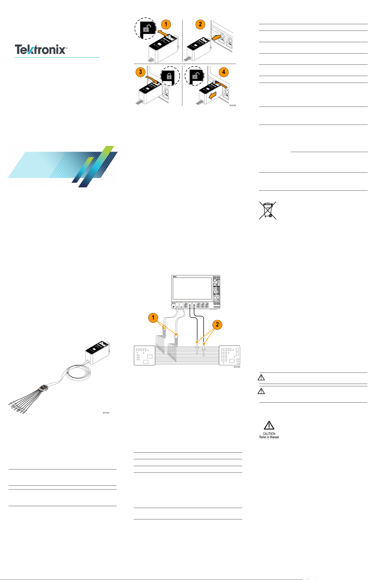
Connecting the probe to the oscilloscope
1. Move the locking lever to the unlocked position then let
go to reset locking lever to the center position.
2. Insert the probe into a FlexChannel channel until fully
seated and the lock mechanism clicks.
3. Mov
e the locking lever to the locked position. The status
light should be a solid green.
E. It is normal for the logic probe Status light to flash
NOT
green when the oscilloscope is powering on, and will turn to a
ady green once the oscilloscope is fully running.
ste
NOTE. If the status LED continues flashing green, flashing
, or is a steady red, contact Tektronix Customer Support
red
for assistance.
4. To r
emove the probe, move and hold the locking lever at
the unlocked position and pull out the probe.
1. Use the logic probe to view digital signals on a system bus.
2. Use an analog probe to view analog waveform information
of a digital signal.
Accessories
The probe comes standard with a Logic Probe Accessory Kit
(Tektronix part number 020-3170-XX). See the illustration on
the following page. See the label in the accessories box lid for
information on the individual accessories.
Specifications
Table 1: Electrical and mechanical specifications
Characteristic Description
Input channels 8 digital
tresistance
Inpu
Input capacitance 3.0 pF
Input signal swing
Minimum 400 mV p-p
Maximum
imum nondest–
Max
ructive input signal
100 kΩ ±1.0%
30 V p-p, ≤200 MHz (centered around
DC threshold voltage) at the probe tip
the
10 V p-p, ≥200 MHz (centered around
the DC threshold voltage) at the probe tip
p-p, ±42 V peak, ±50 V
30 V
DC
Do not operate in wet/damp cond itions.
Do not operate in an explosive atmosphere.
Keep product surfaces clean and dry.
Safety terms and symbols in this manual.
These terms may appear in this manual:
WARNING. Warning statements identify conditions or
practices that could result in injury or loss of life.
CAUTION. Caution statements identify c onditions or
practices that could result in damage to this product or
other property.
Symbols on the product. This symbol may appear on the
product:
Contacting Tektronix
Web site: www.tektronix.com
Phone: 1-800-833-9200
Address: Tektronix, Inc.
Email:
ranty information
War
Department or name (if known)
14200 SW Karl Braun
Drive P.O. Box 500
Beaverton, OR 97077
USA
techsupport@tektronix.com
For warranty information, go to ww w.tektronix.com/warranty.
x
Page 2
Connecting the probe to the circuit
Copyright © Tektronix, Inc. All rights reserved. www.tek.com
Page 3
xx
特性 概要
最大非破壊入力信
号
スレッショルド電
圧
検出可能最小パル
ス幅
最大入力トグル・
レート
最大サンプル・
レート
DAトリガ・ス
キュー
プローブ長
30 V p-p、±42Vピーク、±50 V
±40 V
1ns
500 MHz
6.25 GS/s
5ns
1.0 m(3.28フィート)
DC
TLP058
FlexChannel
取扱説明書
2
15-03
071-35
®
ロジック・プローブ
プローブと測定回路の接続
プローブを回路に接続するには、本書の末尾に記載され
ているコネクタとアダプタを使用します。最適な方法を
選んで、次の「プローブのセットアップ」に進んでくだ
さい。
プローブのセットアップ
ロジック・プローブを接続すると、オシロスコープが自
動的にチャンネルを検出して構成します。
デジタル・チャンネルのパラメータを設定したり表示
するには、プローブが接続されているチャンネルをディ
スプレイに追加します。ロジック・プローブ・チャンネ
ルの波形バッジをダブルタップして、設定メニューを開
きます。デジタル・チャンネルの設定には、スレッショ
ルド電圧(デフォルトは1.4V)、信号高さ(全チャンネ
ル)、チャンネル・ラベルがあります。
プローブの使用
デジタル・ロジック信号とバスの表示方法および始動方
法については、オシロスコープのマニュアルとヘルプ・
トピックを参照してください。
機能チェック
プローブとオシロスコープの接続およびプローブの設
定については、次の指示に従ってください。プローブの
リードをDUTのアクティブなロジック信号に接続しま
す。アクティブなチャンネルにすべて接続したらすぐに
ロジック状態を確認してください。アクティブな信号が
表示されない場合は、アナログ・プローブを使用してロ
ジック信号ポイントの信号状態を確認してください。
表 4: 環境仕様
特性 概要
温度
動作時
非動作時
湿度
動作時
非動作時
高度
動作時
非動作時
0 ℃ ~+50 ℃(+32 °F~+122 °F)
–40°C~+71°C(–40°F~+160°F)
結露なし、最高湿球温度39℃(+102 ゚
F)
まで)
(+104°F~122°F))
°F)まで)
相対湿度5%~39%(+40 ℃~60 ℃(+
104 °F~140 °F))
機器のリサイクル:このマークは、本
製品がWEEE(廃棄電気・電子機器)お
よ び バ ッ テ リ に 関 す る 指 令 2012/19/EU
および200
要件に準拠していることを示していま
す。リサイクル方法については、当社
のWebサイトのサービス・セクション
(www.tek.com/productrecycling)を参照し
てください。
相対湿度5%~90%(+40 ℃(104°F)
相対湿度5%~55%(+40 ℃~+50 ℃
相対湿度5%~90%(+40 ℃(+104
最高3,000m(9,842フィート)
最高12,000 m(39,370 フィート)
6/66/ECに基づき、EUの諸
製品の説明
TLP058型FlexChannel®ロジック・プローブは、
FlexChannel®入力を装備した計測器を被測定デバイス
(DUT)のデジタル・バス/信号に接続するのに使用
します。TLP058ロジック・プローブはどのFlexChannel
オシロスコープ入力チャンネルにも接続できます。
すべてのリードのチップにはグランド接続があります。
プローブ・リードは、ターゲット・システムに個別に接
続したり、プローブのチップ・ホルダを使用してグルー
プ化したりすることができます。
オシロスコープへのプローブの接続
1. ロック・レバーをアンロック位置に移動させ、ロッ
ク・レバーが中央に戻るまで待ちます。
2. FlexChannelチャンネルにプローブを挿入し、プロー
ブが完全に挿入されてロック・メカニズムのカチッ
という音がするまで押し込みます。
3. ロック・レバーをロック位置に移動させます。ス
テータス
注: ロジック・プローブのステータス・ライトは正常で
あれば、
点滅し、オシロスコープが完全に作動すると緑色の点灯
に変わり
注: ステータスLEDが緑色に点滅し続ける、赤色に点滅
し続け
マ・サポートにご連絡ください。
4. プロー
ロック位置に移動させたままプローブを引き抜きま
す。
・ライトが緑色に点灯します。
オシロスコープの電源が入ったときには緑色に
ます。
る、または赤色に点灯する場合には、当社カスタ
ブを取り外すには、ロック・レバーをアン
主な用途
1. ロジック・プローブは、システム・バスのデジタル
信号の観測に使用します。
2. アナログ・プローブはアナログ波形情報の確認に使
用します。
アクセサリ
このプローブには、標準付属品としてロジック・プロー
ブ・アクセサリ・キット(当社部品番号:020-3170-XX)
がついています。次のページの図をご覧ください。アク
セサリの個別の情報については、アクセサリの箱のふた
に貼付されているラベルをご覧ください。
仕様
表 3: 電気仕様と機械仕様
特性 概要
入力チャンネル数
入力抵抗
入力キャパシタン
ス
入力信号スイング
最小値
最大値
8デジタル
100 kΩ ±1.0%
3.0 pF
mV p-p
400
30 V p-p、200 MHz以下(プロー
ブ・チップで、DCスレッショルド
電圧を中心に)
p-p、200 MHz以上(プロー
10 V
ブ・チップで、DCスレッショルド
電圧を中心に)
安全にご使用
いただくために
接続と切断は正しく行うこと。: 測定対象の回路にプローブ
を接続する前
に、プローブ出力を測定機器に接続してく
ださい。測定機器からプローブを外す前に、測定対象の
回路からプロ
すべての端子
ーブの入力とグランドを外してください。
の定格に従うこと。: 火災や感電の危険を避
けるために、本製品のすべての定格とマーキングに従っ
てください。
本製品に電源を接続する前に、定格の詳細
について、製品マニュアルを参照してください。プロー
ブの基準リー
カバーを外
ドは、グランドにのみ接続してください。
した状態で動作させないこと。:
露出した回路への接触は避けること。: 電源が投入されて
いるときに
、露出した接続部分やコンポーネントに触れ
ないでください。
故障の疑いがあるときは使用しないこと。: 本製品に故障
の疑いがあ
る場合、資格のあるサー ビス担当者に検査
してもらってください。
湿気の多いところでは動作させないこと。:
爆発性のガ
スがある場所では使用しないこと。:
製品の表面を清潔で乾燥した状態に保つこと。:
安全に関する用語と記号
このマニュ
アルでは次の用語を使用します。
警告: 人体や生命に危害をおよぼすおそれのある状
態や行為を
注意: 本製
示します。
品やその他の接続機器に損害を与えるお
それのある状態や行為を示します。
本製品の記号:: 本製品は以下の記号に注意してご使用
ください
。
当社へのお問合せ
tektronix.com
Webサイト:
号:
電話番
住所:
電子メール・ア
ドレス:
www.
00-833-9200
1-8
Tektronix, Inc.
部署名または個人名(わかる場合)
14200 SW Karl Braun
Drive P.O. Box 500
verton, OR 97077
Bea
USA
techsupport@tektronix.com
x
Page 4

保証
保証の詳細については、
http://www.tektronix.com/warranty に ア ク セ ス
してください。
プローブと測定回路の接続
Copyright © Tektronix, Inc.All rights reserved. www.tek.com
Page 5

xx
TLP058
FlexChannel
说明
®
逻辑探头
将探头连接到电路
使用这些使用说明背面所示的连接器和适配器,将探头
连接到电路。选择适合需要的最佳方法,然后进行探头设
置。
设置探头
连接逻辑探头时示波器将自动检测和配置通道。
要设置和查看数字通道参数,请将已连接逻辑探头的通道
添加到显示器。双击逻辑探头通道的波形标记,打开配置
菜单。数字通道设置包括阀值电压(默认为 1.4 V)、信
号高度(所有通道)和通道标签。
使用探头
有关如何显示和触发数字逻辑信号和总线的信息,请参阅
示波器文档和帮助主题。
特性 说明
最小可检测脉宽
最大输入切换速率
最大取样速率
数字转模拟触发时
延
探头长度 1.0 米(3.28 英尺)
1ns
500 MHz
6.25 GS/s
5ns
表 6: 环境技术规格
特性 说明
温度
工作状态
非工作状态
湿度 无冷凝,且受限于 +39 °C (+102 °F)
工作状态 在不高于 +40 ℃ (104 °F) 时,相对湿
非工作状态 在不高于 +40 ℃ (+104 °F) 时,相对
海拔高度
工作状态
非工作状态
0℃至+50℃(
–40 °C 至 +71 °C(–40 °F 至
+160 °F)
的最大湿球温度
度为 5% 至 90
5 至 55% 相对湿度 +40 °C 至 +50 °C
(+104 °F 至 122 °F)
湿度为 5% 至 90%
5 至 39% 相对湿度 +40 °C 至 +60 °C
(+104 °
最高 3,000 米(9,842 英尺)
最高 12000 米(39370 英尺)
+32 ℉ 至 +122 ℉)
%
F至140°F)
3
15-03
071-35
产品说明
TLP058 FlexChannel® 逻辑探头在被测设备 (DUT) 上将带
FlexChannel® 输入端的所有仪器接入数字总线和 信号。
探头包含 8 个数据通道。您可以将 TLP058 逻辑探头连
接到任何 FlexChannel 示波器输入通 道。
所有导线在端部都有一个地线连接。可将探头引线分别连
接到目标系
统,或者使用探头端部支持臂将引线分组。
功能检查
请按照说明将探头连接到示波器并设置探头。将探头导线
连接到您的 DUT 上的活跃逻辑信号。您应该看到逻辑活
动立即显示在所有连接的活动通道上。如果未看到活跃信
号,请使用模拟探头以验证逻辑信号点上的信号活动。
典型应用
1. 使用逻辑探头查看系统总线上的数字信号。
2. 使用模拟探头查看数字信号的模拟波形信息。
附件
探头标准随附逻辑探头附件套件(泰克部件号
020-3170-XX)。请参阅下页的图解。有关每个附件的信
息,请参阅附件盒盖上的标签。
设备的回收。此符号表示该产品符合欧
盟有关废旧电子和电气设备 (WEEE) 以
及电池的 20
号指令所规定的相关要求。有关回收
选项的信息,请登录 Tektronix 网 站
(www.tek.com/productrecycling) 查看。
12/19/EU 和 2006/66/EC
安全概要
正确连接并
正确断开连接: 将探头连接到被测电路之前,
先将探头输出端连接到测量仪器。将探头与测量仪器断开
之前,先将
遵守所有终
探头输入端及探头接地与被测电路断开。
端额定值: 为避免火灾或电击危险,请遵守产
品上所有的额定值和标记说明。在连接产品之前,请先查
看产品手册
,了解额定值的详细信息。只能将探头参考导
线连接到大地。
切勿开盖操作:
远离外露电
怀疑产品出
路: 电源接通后请勿接触外露的接头和元件。
现故障时,请勿进行操作: 如果您怀疑此产品
已损坏,可请合格的维修人员进行检查。
请勿在潮湿环境下操作:
请勿在易
燃易爆的环境下操作:
请保持产品表面清洁干燥:
本手册中使用的安全术语和符号。
本手册中
可能出现以下术语:
警告: “警告”声明指出可能会造成人身伤害或危及
生命安全
的情况或操作。
注意: “注意”声明指出可能对本产品或其他财产造
成损坏的
情况或操作。
产品上的符号: 产品上可能出现以下符号:
将探头连接到示波器
1. 将锁定杆移动到未锁定位置,然后释放以将锁定杆重
置到中心位置。
2. 将探头
插入 FlexChannel 通道,直到完全到位并听
到锁定机构发出“咔”的声音。
3. 将锁定杆移动到锁定位置。状态灯应长亮绿色。
说明: 当示波器打开时逻辑探头状态灯闪烁绿色,然后
在示波器完全运行后再变为长亮绿色,这是正常情况。
说明: 如果状态 LED 持续闪烁绿色、闪烁红色或长亮红
色,则联系泰克客户支持寻求协助。
4. 要取下探头,请将锁定杆移动到未锁定位置并按住,
然后拉出探头。
技术规格
表 5: 电气和机械技术规格
特性 说明
输入通道 8 个数字通道
输入电阻
输入电容
输入信号
最大无
阈值电压
摆动
最小值
最大值 30 V p-p,探头端部 ≤200 MHz(以
损输入信号
100 kΩ ±1.0%
3.0 pF
400 mV p-p
直流阈值电压为中心)
10 V p-p,探头端部 ≥200 MHz(以
直流阈值电压为中心)
p-p,±42V峰值,±50V
30 V
±40 V
Tektronix 联系信息
网站:
电话:
地址:
电子邮件:
DC
保修信息
www.tektronix.com
0-833-9200
1-80
Tektronix, Inc.
部门或姓名(如已知)
14200 SW Karl Braun
Drive P.O. Box 500
erton,OR 97077
Beav
USA
techsupport@tektronix.com
有关保修信息,请访问 www.tektronix.com/warranty。
x
Page 6

将探头连接到电路
版权所有 © Tektronix, Inc.保留所有权利。 www.tek.com
Page 7

xx
TLP058
Логический пробник FlexChannel
®
Указания
4
15-03
071-35
Описание изделия
Логический пробник TLP058 FlexChannel® предназначен
для подсоединения цифровых шин и цепей тестируемых
устройств к любым приборам с входами FlexChannel®. В
пробнике имеется 8 каналов данных. Логический пробник
TLP058 можно подключить к любому входному каналу
FlexChannel осциллографа.
Все измерительные кабели снабжены наконечником с
ктом заземления. Измерительные провода пробника
конта
можно подключать к исследуемой схеме по отдельности
руппировать наконечники проводов в пакет с
или сг
помощью группового держателя наконечников.
1. Переведите рычажок запорного механизма в
положение « открыто»
, азатемвернитееговсреднее
положение.
2. Вставьте пробник в соединитель канала FlexChannel
до упора и щелчка запорного механизма.
3. Переведите рычажок запорного механизма в
положение « закрыто». Индикатор состояния должен
непрерывно светиться зеленым.
ПРИМЕЧАНИЕ. Мигание зеленого сигнала индикатора
состояния при включении осциллографа с последующей
сменой на непрерывный зеленый сигнал при входе
осциллографа в нормальный рабочий режим является
нормой.
ПРИМЕЧАНИЕ. Если светодиод индикатора состояния
продолжает подавать мигающий зеленый или красный
сигнал, или постоянный красный сигнал, следует
обратиться в службу поддержки потребителей компании
Tektronix (Tektronix Customer Support) за помощью.
4. Для извлечения пробника переведите и удерживайте
рычажок запорного механизма в положении
«открыто», одновременно вытягивая пробник.
Подключение пробника к проверяемой цепи
Подключите пробник к цепи с помощью соединителей
и адаптеров, изображенных на оборотной стороне
настоящего руководства. Выберите наиболее подходящий
вданномслучаеспособ, затем выполните настройку
пробника.
Настройка пробника
Осциллограф автоматически определяет подключение
логического пробника и выполняет настройку
конфигурации каналов.
Для задания и отображения значений параметров
цифрового канала добавьте канал с подключенным
логическим пробником в список отображаемых. Для
вывода меню конфигурации дважды щелкните по значку
осциллограммы канала с подключенным логическим
пробником. Настраиваемые параметры цифрового канала
включают значение порогового напряжения (равное по
умолчанию 1,4 В), амплитуду сигнала (для всех каналов)
иметкиканалов.
Использование пробника
Для получения сведений об методах отображения
и использования логических сигналов и шин для
синхронизации обратитесь к документации на осциллограф
и разделам справочной системы Help.
Контроль функционирования
Подключите пробник к осциллографу и настройте
параметры пробника согласно инструкции. Подключите
измерительные провода пробника к точкам с актив
ными
логическими сигналами проверяемого устройства. Наличие
активности в логических цепях всех подключенны
х
активных каналов немедленно отображается на экране.
Если активный сигнал не отображается, проверьт
е наличие
логических сигналов в точках подключения с помощью
аналогового пробника.
Технические характеристики
Таблица 7: Электрические и механические характеристики
Параметр Описание
Число входных
каналов
Входное
сопротивление
Входная емкость 3,0 пФ
Размах входного
сигнала
Минимальный 400 мВ размах
Максимальный
Максималь
безопасный входной
сигнал
Пороговое
напряжение
Минимальная
обнаруживаемая
длительность
импульса
Максимал
переключения на
входе
Максимальная частота
выборок
Задержка
цифро-аналогового
преобразования
Длина пр
ный
ьная частота
обника
8 цифровых
100 кОм ±1,0%
30 Вразмах, ≤200 МГц (с центром около
пороговог
тока) на наконечнике пробника
10 Вразмах, ≥200 МГц (с центром около
порогового напряжения постоянного
тока) на наконечнике пробника
30 В размах
тока
±40В
1 нс
500 МГц
6,25 Гвыб/с
5 нс
1,0 м (3,
о напряжения постоянного
,±42Вразмах,±50В
28 фута)
постоянного
Таблица 8: Характеристики окружающей среды
Параметр Описание
Температура
Рабочая
Хранения
Влажность При максимальной температуре влажного
Рабочая Относительная влажность от 5 до 90 % при
Хранения
Высота над
уровнем моря
Рабочая
Хранения
От 0 до +50 °C (от +32 до +122 °F)
От –40 до +71 °C (от -40 до +160 °F)
метра +39 °C (+102 °F), без конденсации
термо
температуре до 40 °C (104 °F)
Относительная влажность от 5 до 55 % при
температуре от +40 до +50 °C (от +104 до
122 °F)
Относительная влажность от 5 до 90 % при
температуре до +40 °C (+104 °F)
Относительная влажность от 5 до 39 % при
ратуре от +40 до +60 °C (от +104 до
темпе
+140 °F)
Максимальная 3000м (9 842 фута)
Максимальная 12 000 м (39 370 футов)
Подключение пробника к осциллографу
Типовой способ применения
1. Использование логического пробника для отображения
цифровых сигналов системной шины.
2. Использование аналогового пробника для отображения
формы цифрового сигнала в аналоговом виде.
Принадлежности
Обычно логический пробник поставляется в комплекте
с набором принадлежностей Logic Probe Accessory
Kit (номер по каталогу Tektronix 020-3170-XX). См.
иллюстрации на последующих страницах. Для получения
сведений о каждой принадлежности см. наклейку на
крышке коробки с принадлежностями.
Утилизация оборудования. Этот символ
указывает на соответствие данного прибора
енимым нормам Европейского союза согласно
прим
директивам 2012/19/EU и 2006/66/EC об утилизации
электрического и электронного оборудования
(WEEE) и элементов питания. Информация о
способах утилизации приведена на веб-сайте
компании Tektronix (www.tek.com/productrecycling).
Общие правила безопасности
Соблюдайте правила подключения и отключения. Сперва
подключите выход пробника к измерительному прибору, а
затем пробник к проверяемой цепи. Сперва отключайте
вход пробника и провод заземления от проверяемой цепи, а
затем пробник от измерительного прибора.
Соблюдайте допустимые предельные значения для всех
соединителей и клемм. Во избежание воспламенения
или травмирования электрическим током соблюдайте
всепредельныезначенияинанесенныенаприбор
указания. Ознакомьтесь с дополнительными сведениями
о предельных значениях параметров в руководстве по
эксплуатации перед подключением прибора. Общий вывод
пробника следует подключать только к заземлению.
Не используйте прибор со снятым кожухом.
Не прикасайтесь к оголенным участкам электрических
цепей. Не прикасайтесь к оголенным соединениям и к
элементам под напряжением.
Не используйте прибор при наличии сомнений в его
исправности. При наличии подозрений в неисправности
прибора следует проверить его у квалифицированных
специалистов сервисного центра.
x
Page 8

Не пользуйтесь прибором в условиях повышенной
влажности.
Не эксплуатируйте прибор во взрывоопасной обстановке.
Храните прибор в чистоте в сухом месте.
Условные обозначения и символы безопасности,
используемые в данном руководстве по эксплуатации.
В настоящем руководстве использованы приведенные ниже
условные обозначения:
ПРЕДУПРЕЖДЕНИЕ. Предупреждения о действиях и
условиях, опасных для жизни или способных нанести
вред здоровью.
Символы, наносимыенаприбор. Ниже приведен символ,
который может быть нанесен на изделие:
Как связаться с компанией Te ktro nix
Веб-сайт:
Телефон: 1-800-833-9200
Адрес: Tektronix, Inc.
Электронна
почта:
я
www.tektron
Отдел или имя (если известно)
14200 SW Karl Braun
Drive P.O. Box 500
Beaverton, OR 97077
США
techsuppor
ix.com
t@tektronix.com
ОСТОРОЖНО. Предостережение о действиях и
условиях, способных привести к повреждению данного
прибора или другого оборудования.
Подсоединение пробника к цепи
Гарантийные обязательства
Информацию о гарантийных обязательствах см. на
веб-сайте www.tektronix.com/warranty.
Авторские права © Tektronix, Inc. Все права защищены. www.tek.com
 Loading...