

Page 1

TLA7S08 & TLA7S16
Serial Analyzer Modules
Technical Reference
This document applies to TLA System Software Version 5.1
or higher
Warning
These servicing instructions are for use by qualified personnel
only. To avoid personal injury, do not perform any servicing
unless you are qualified to do so. Refer to all safety summaries
prior to performing service.
www.tektronix.com
071-2188-00
Page 2

Copyright © Tektronix. All rights reserved. Licensed software products are owned by Tektronix or its subsidiaries
or suppliers, and are protected by national copyright laws and international treaty provisions.
Tektronix products are covered by U.S. and foreign patents, issued and pending. Information in this publication
supersedes that in all previously published material. Specifications and price change privileges reserved.
TEKTRONIX and TEK are registered trademarks of Tektronix, Inc.
PCI Express is a registered trademark of PCI-SIG®.
Contacting Tektronix
Tektronix, Inc.
14200 SW Karl Braun Drive
P.O . B o x 5 00
Beaverton, OR 97077
USA
For product information, sales, service, and technical support:
In North America, call 1-800-833-9200.
World wi de, vis i t www.tektronix.com to find contacts in your area.
Page 3

Warranty 2
Tektronix warrants that this product will be free from defects in materials and workmanship for a period of one (1)
year from the date of shipment. If any such product proves defective during this warranty period, Tektronix, at its
option, either will repair the defective product without charge for parts and labor, or will provide a replacement
in exchange for the defective product. Parts, modules and replacement products used by Tektronix for warranty
work may be ne
the property of Tektronix.
w or reconditioned to like new performance. All replaced parts, modules and products become
In order to o
the warranty period and make suitable arrangements for the performance of service. Customer shall be responsible
for packaging and shipping the defective product to the service center designated by Tektronix, with shipping
charges prepaid. Tektronix shall pay for the return of the product to Customer if the shipment is to a location within
the country in which the Tektronix service center is located. Customer shall be responsible for paying all shipping
charges, duties, taxes, and any other charges for products returned to any other locations.
This warranty shall not apply to any defect, failure or damage caused by improper use or improper or inadequate
maintenance and care. Tektronix shall not be obligated to furnish service under this warranty a) to repair damage
resulti
b) to repair damage resulting from improper use or connection to incompatible equipment; c) to repair any damage
or malfunction caused by the use of non-Tektronix supplies; or d) to service a product that has been modified or
integrated with other products when the effect of such modification or integration increases the time or difficulty
of servicing the product.
THIS WARRANTY IS GIVEN BY TEKTRONIX WITH RESPECT TO THE PRODUCT IN LIEU OF ANY
OTHER WARRANTIES, EXPRESS OR IMPLIED. TEKTRONIX AND ITS VENDORS DISCLAIM ANY
IMPLIED WARRANTIES OF MERCHANTABILITY OR FITNESS FOR A PARTICULAR PURPOSE.
TEKTR
AND EXCLUSIVE REMEDY PROVIDED TO THE CUSTOMER FOR BREACH OF THIS WARRANTY.
TEKTRONIX AND ITS VENDORS WILL NOT BE LIABLE FOR ANY INDIRECT, SPECIAL, INCIDENTAL,
OR CONSEQUENTIAL DAMAGES IRRESPECTIVE OF WHETHER TEKTRONIX OR THE VENDOR HAS
ADVANCE NOTICE OF THE POSSIBILITY OF SUCH DAMAGES.
btain service under this warranty, Customer must notify Tektronix of the defect before the expiration of
ng from attempts by personnel other than Tektronix representatives to install, repair or service the product;
ONIX’ RESPONSIBILITY TO REPAIR OR REPLACE DEFECTIVE PRODUCTS IS THE SOLE
Page 4

Page 5

Table of Contents
General Safety Summary ......................................................................................... iv
Service Safety Summary........................................ ................................ .................. vi
Preface ............................................................................................................. vii
Manual Conven
Related Documentation ..................................................................................... vii
Introduction ........................................................................................................ ix
Service Strategy..................................... .................................. ........................ ix
Service Offerings ............................................................................................. ix
Maintenance......................................................................................................... 1
Preventing E
Inspection and Cleaning.......................... ................................ ............................. 1
Removal and Installation ................... ................................ .................................. ..... 5
Tools Required ................................................................................................. 5
Torque Requirements.......................................................................................... 5
Covers.............. .................................. ................................ ........................... 6
Local Proces
Acquisition Board ... ... . ... . ... .... ... . ... . ... ... . ... . ... .... ... . ... . ... ... . ... . ... .... ... . ... . ... ... . ... . ... . 9
EMI Gaskets................................................................................................... 10
Troubleshooting.................................................................................................... 13
Check for Common Problems ........................... ................................ .................... 14
Eliminate Other Problem Sources........................................................................... 15
Troublesho
Updating the Module Firmware..... ................................ ................................ ........ 20
Repackaging Instructions ......................................................................................... 21
Parts List............................................................................................................ 22
Parts Ordering Information .................................................................................. 22
Using the Replaceable Parts List............................................................................ 23
tions............................................ ................................ ............. vii
SD ................................................................................................ 1
sor Unit (LPU) Board .......................................................................... 8
ot the Module .................................................................................... 15
TLA7S08 & TLA7S16 Serial Analyzer Technical Reference Manual i
Page 6

Table of Contents
List of Figure
Figure 1: Installing the cover onto the chassis .. . ... ... . ... .... ... . ... ... . ... . ... .... ... . ... ... . ... . ... .... ... . . 6
Figure 2: Sea
Figure 3: Rear EMI gasket removal ............................................................................. 10
Figure 4: Side EMI gasket installation.......................................................................... 11
Figure 5: TLA7S08 &TLA7S16 chassis and cover ........... ................................ ................ 24
Figure 6: TLA7S08 &TLA7S16 circuit board assemblies.................................................... 26
Figure 7: TLA7S08 &TLA7S16 internal cables and connectors......................................... .... 28
ting the cover on the chassis...... ................................ ................................ . 7
s
ii TLA7S08 & TLA7S16 Serial Analyzer Technical Reference Manual
Page 7

List of Tables
Table i: Related Documentation ............. ................................ ................................ ... viii
Table 1: Exte
Table 2: Internal inspection check list..... ................................ .................................. ..... 3
Table 3: Tools required for circuit board replacement.......................................................... 5
Table 4: Failure symptoms and possible causes.................................... ............................ 14
Table 5: Diagnostic tests.......................................................................................... 19
Table 6: Parts list column descriptions.......................................... ................................ 23
rnal inspection check list........................................................................... 2
Table of Contents
TLA7S08 & TLA7S16 Serial Analyzer Technical Reference Manual iii
Page 8

General Safety Summary
General Safet
To Avoid Fire or Personal
Injury
ySummary
Review the fol
this product or any products connected to it.
To avoid pote
Only qualified personnel should perform service procedures.
While using this product, you may need to access other parts of a larger system.
Read the safety sections of the other component manuals for warnings and
cautions re
Ground the Product. This product is indirectly grounded through the grounding
conductor of the mainframe power cord. To avoid electric shock, the grounding
conductor must be connected to earth ground. Before making connections to
the input or output terminals of the product, ensure that the product is properly
grounde
Observe All Terminal Ratings. To avoid fire or shock hazard, observe all ratings
and mark
information before making connections to the product.
The inp
uts are not rated for connection to mains or Category II, III, or IV circuits.
lowing safety precautions to avoid injury and prevent damage to
ntial hazards, use this product only as specified.
lated to operating the system.
d.
ings on the product. Consult the product manual for further ratings
TermsinthisManual
Do not apply a potential to any terminal, including the common terminal, that
exceed
Power Disconnect. The power cord disconnects the product from the power source.
Do not
Do Not Operate Without Covers. Do not operate this product with covers or panels
remov
Do Not Operate With Suspected Failures. If you suspect that there is damage to this
prod
Avoid Exposed Circuitry. Do not touch exposed connections and components
when
Do Not Operate in Wet/Damp Conditions.
Do Not Operate in an Explosive Atmosphere.
Keep Product Surfaces Clean and Dry.
Provide Proper Ventilation. Refer to the manual’s installation instructions for
det
These terms may appear in this manual:
s the maximum rating of that terminal.
block the power cord; it must remain accessible to the user at all times.
ed.
uct, have it inspected by qualified service personnel.
power is present.
ails on installing the product so it has proper ventilation.
iv TLA7S08 & TLA7S16 Serial Analyzer Technical Reference Manual
Page 9

General Safety Summary
WAR N ING. Warning statements identify conditions or practices that could result
in injury or lo
CAUTION. Caution statements identify conditions or practices that could result in
damage to th
ss of life.
is product or other property.
Symbols and Terms on the
Product
These terms may appear on the product:
DANGER indicates an injury hazard immediately accessible as you read
the marking.
WARNING indicates an injury hazard not immediately accessible as you
read the marking.
CAUTION indicates a hazard to property including the product.
The following symbol(s) may appear on the product:
TLA7S08 & TLA7S16 Serial Analyzer Technical Reference Manual v
Page 10

Service Safety Summary
Service Safet
y Summary
Only qualified
Safety Summary and the General Safety Summary before performing any service
procedures.
Do Not Service Alone. Do not perform internal service or adjustments of this
product unless another person capable of rendering first aid and resuscitation is
present.
Disconnect Power. To avoid electric shock, switch off the instrument power, then
disconnect the power cord from the mains power.
Use Care When Servicing With Power On. Dangerous voltages or currents may
exist in t
disconnect test leads before removing protective panels, soldering, or replacing
components.
To avoid electric shock, do not touch exposed connections.
his product. Disconnect power, remove battery (if applicable), and
personnel should perform service procedures. Read this Service
vi TLA7S08 & T LA7S16 Serial Analyzer Technical Reference Manual
Page 11

Preface
Manual Conventions
Preface
This manual uses certain conventions that you should be familiar with before
attempting service.
Acquisition Board
LPU Board
Maintenance Procedures
Modules
Replaceable Parts
The acquisition board is one of the circuit boards inside the instrument module.
The circuit board receives and stores acquisition data from the probes and works
with the Local Processor Unit (LPU) board to provide information to the operator
of the instrument.
The Local Processor Unit (
instrumentmodule that provides the main communications interface with the
acquisition board and the mainframe.
Maintenance procedures are used for fault isolation and repair to the circuit board
level or to the replaceable part level.
Throughout this manual, the terms “module” or “instrument module” refers to
a logic analyzer, serial analyzer, or pattern generator unit that mounts inside a
mainframe. A module is composed of circuit boards, interconnecting cables, and
a user-accessible front panel.
This manual refers to any field-re
specifically by its name or generically as a repla ceable part. In general, a
replaceable part is any circuit board or assembly that is listed in the replaceable
parts list near the end of this manual.
LPU) board is one of the circuit boards inside the
placeable assembly or mechanical part
Safety
Symbols and terms related to safety appear in the S afety Summary found at the
beginning of this manual.
Related Documentation
The following table lists related documentation available for your instrument. The
documentation is available on the TLA Documentation CD, included with your
instrument, and on the Tektronix Web si
To obtain documentation not specified in the table, contact your local Tektronix
representative.
TLA7S08 & TLA7S16 Serial Analyzer Technical Reference Manual vii
te (www.Tektronix.com).
Page 12

Preface
Table i: Relate
Item Purpose Location
TLA Quick Star
Online Help
Installation
Installation Manuals
XYZs of Logic Analyzers
TLA Product Specifications Complete list of TLA product
TPI.NET Documentation
Field upgrade kits
d Documentation
t User Manual
Quick Reference Cards
Basic operational overview
In depth operation and UI help
Basic install
Detailed first-time installation information
Introductio
specifications
Detailed inf
logic analyzer using .NET
Upgrade information for your logic
analyzer product
ation information
n to logic analyzer basics
ormation for controlling the
Optional Service Manuals Self-service documentation for modules
and mainframes
TLA Application Software Release Notes Software description, compatibility,
impact of changes, contact information,
installation, upgrade, and operational
notes, and known issues.
Go to Start→All Programs→Tektronix
logic Analyzer→TLA Release Notes
viii TLA7S08 & TLA7S16 Serial Analyzer Technical Reference Manual
Page 13

Introduction
Service Strategy
This manual contains information needed to service the TLA7S08 and
TLA7S16 serial analyzer modules.
To prevent personal injury or damage to the instrument, consider the following
requirements before attempting service:
Read the General Safety Summary and Service Safety Summary found at
the beginning of this manual.
The procedures in this m anual should only be performed by a qualified service
person.
Be sure to follow all warnings, cautions and notes.
This manual supports and contains information needed for periodic maintenance
of the instrument. It supports and contains
corrective maintenance:
Supports removal and replacement of boards or assemblies.
the following information for
Service Offerings
Warranty Repair Service
Calibration and Repair
Service
Supports removal and replacement of the mechanical parts listed in the parts
lists.
This manual does not support component-level fault isolation and replacement.
Tektronix provides service to cover repair under warranty as well as other services
that are designed to meet your specific service needs.
Whether providing warranty repair service or any of the other services listed
below, Tektronix service technicians are equipped to service the instrument.
Services are provided at Tektronix Services Centers and on-site at your facility,
depending on your location.
Tektronix warrants this product for one year from date of purchase. The warranty
is located behind the title page in this manual. Tektronix technicians provide
warranty service at most Tektronix service locations worldwide. The Tektronix
product catalog lists all service locations worldwide.
In addition to warranty repair, Tektronix Service offers calibration and other
services which provide solutions to your service needs and quality standards
compliance requirements.
TLA7S08 & TLA7S16 Serial Analyzer Technical Reference Manual ix
Page 14

Introduction
The following s
and/or repair of your portable mainframe.
Service Options. Tektronix Service Options can be selected at the time you
purchase your instrument. You select these options to provide the services that
best meet your service needs.
Service Agreement. If ser vice options are not added to the instrument purchase,
then service agreements are available on an annual basis to provide calibration
services or post-warranty repair coverage. Service agreements may be customized
to meet special turn-around time and/or on-site requirements.
Service on
“per-incident” basis that is available with standard prices.
Self Service. Tektronix supports repair to the replaceable-part level by providing
for circuit board exchange.
Use this service to reduce down-time for repair by exchanging circuit boards for
remanufactured ones. Tektronix ships updated and tested exchange boards. Each
board comes with a 90-day service warranty.
For More Information. Contact your local Tektronix service center or sales
engineer for more information on any of the Calibration and Repair Services
just described.
ervices can be tailored to fit your requirements for calibration
Demand. Tektronix offers calibration and repair services on a
x TLA7S08 & TLA7S16 Serial Analyzer Technical Reference Manual
Page 15

Maintenance
Preventing ESD
WAR N ING. To avoid electric shock, always power off the instrument and
disconnect the power cord before cleaning or servicing the instrument.
When perform
adhere to the following precautions to avoid damaging internal circuit boards and
their components due to electrostatic discharge (ESD).
CAUTION. Many components within the instrument are susceptible to static
discharge damage.
Service the instrument only in a static-free environment. Observe standard
handling p
Minimize handling of static-sensitive circuit boards.
Transport and store static-sensitive circuit boards in their static protected
containers or on a metal rail. Label any package that contains static-sensitive
boards.
Discharge the static voltage from your body by wearing a grounded antistatic
wrist st
Nothing capable of generating or holding a static charge should be allowed
on the w
Handle circuit boards by the edges when possible.
ing any service which requires internal access to the instrument,
recautions for static-sensitive devices.
rap while handling these circuit boards.
ork station surface.
Do not slide the circuit boards over any surface.
Avoid handling circuit boards in areas that have a floororwork-surface
covering capable of generating a static charge.
Inspe
TLA7S08 & TLA7S16 Serial Analyzer Technical Reference Manual 1
ction and Cleaning
The instrument is inspected mechanically and electrically before shipment. It
should be free of marks or scratches and should meet or e xceed all electrical
spec
transit. Retain the packaging in case shipment for repair is necessary. If there
is damage or deficiency, contact your local Tektronix representative. Cleaning
procedures consist of exterior and interior cleaning. Periodic cleaning reduces
instrument breakdown and increases reliability. Clean the instrument as needed,
based on your operating environment.
ifications. To confirm this, inspect for physical damage incurred during
Page 16

Maintenance
Exterior Inspection
Modules that ap
pear to have been dropped or otherwise abused should be checked
thoroughly to verify correct operation and performance. Immediately repair
defects that could cause personal injury or lead to further damage to the benchtop
controller, expansion module, or the mainframes that the module plug into.
Table 1: External inspection check list
Item Inspect for Repair actio
Front panel
Front and rear connectors Broken shells, cracked
Accessories
Cracks, scr
deformations, missing or
damaged retainer screws,
or ejector h
insulation
contacts
Dirt in connectors
Missing items or parts of
items, ben
frayed cables, and damaged
connectors
atches,
andles
, and deformed
t pins, broken or
Replace def
missing parts.
Replace de
Clear dirt out of connectors.
Replace damaged or
missing parts, frayed
cables.
n
ective or
fective parts.
CAUTION. To prevent damage to electrical components from moisture during
external cleaning, use only enough liquid to dampen the cloth or applicator.
Exterior Cleaning
Procedure
Interior Inspection
Clean the exterior surfaces with a soft dry lint-free cloth, or a soft-bristle brush.
If any dirt remains, use a soft cloth or swab dipped in a 75% isopropyl alcohol
solution. Use a swab to clean narrow spaces around controls and connectors. Do
not use abrasive cleaning compounds.
CAUTION. Avoid g etting moisture inside the instrument during exterior cleaning;
ust enough moisture to dampen the cloth or swab.
use j
Use only deionized water when cleaning. Use a 75% isopropyl alcohol solution
as a cleanser and rinse with deionized or distilled water.
Do not use chemical cleaning agents; they may damage the chassis. Avoid
chemicals that contain benzene, toluene, xylene, acetone, or similar solvents.
Remove the module covers to access the inside of the instrument for inspection
and cleaning. (See page 6, Covers.) Inspect the internal portions of the modules
and the mainframes for damage and wear. Defects found should be repaired
immediately.
2 TLA7S08 & TLA7S16 Serial Analyzer Technical Reference Manual
Page 17

Maintenance
Interior
Cleaning
Procedure
Table 2: I ntern
Item Inspect for Repair action
Circuit boards
Solder connections Cold so lder or rosin joints
Wiring and ca
Chassis Dents, deformations, and
al inspection check list
Loose, broken
solder connections.
Burned circuit boards.
Burned, brok
circuit-run plating
bles
Loose plugs o
Burned, broken, or frayed
wiring
damaged har
, or corroded
en, or cracked
r connectors.
dware
Return to a Tek
Service Center.
Return to a Te
Service Center.
Firmly seat c
Repair or replace parts with
defective wires or cables.
Straighten, repair, or replace
defective h
tronix
ktronix
onnectors.
ardware.
CAUTION. To prevent damage from electrical arcing, ensure that circuit boards
and components are dry before applying power.
Use a dry, low-velocity stream of air to clean the interior of the modules and the
mainframes. Use a soft-bristle brush for cleaning around components. If you must
use a liquid for minor interior cleaning, use a 75% isopropyl alcohol solution and
rinse w
ith deionized or distilled water.
TLA7S08 & TLA7S16 Serial Analyzer Technical Reference Manual 3
Page 18

Maintenance
4 TLA7S08 & TLA7S16 Serial Analyzer Technical Reference Manual
Page 19
Removal and Installation
This section provides detailed instructions for removing or installing parts of the
module. The procedures in this sectio n assume that you already have removed
the module from the mainframe. Removal and installation instructions are not
provided for all replaceable parts. (See page 22, Parts List.)
Tools Required
WAR N ING. Be
Summary and Service Safety Summary found at the beginning of this manual.
When performing any service which requires internal access to the instrument,
avoid damaging internal circuit boards and their components by electrostatic
discharge (ESD). (See page 1, Preventing ESD.)
The follow
of the instrument.
Table 3: Tools required for circuit board replacement
Description Example
Screwdriver with a T-9 and a T-10 Torx tip Standard tool
1/4-inch nut driver Standard tool
9/16-inch nut driver Standard tool
Needle-n
fore doing any procedures in this manual, read the General Safety
ing table lists the tools needed to replace the internal components
ose pliers
Standard tool
Torque
TLA7S08 & TLA7S16 Serial Analyzer Technical Reference Manual 5
Requirements
Tighten all T-9 and T-10 screws to 4 in-lbs. Tighten standoff posts to 8 in-lbs.
Page 20

Removal and Installation
Covers
Removal
Installation
Refer to the exploded view of the module to remove the covers. (See Figure 6.)
Use the following procedure to install the covers:
NOTE. Install the cover tightly against the chassis. This will ensure that the
module fits into adjacent slots in the mainframe.
1. Place the module on its right side.
CAUTION. To prevent damage to the module during the installation process,
reinstall the cover exactly as described in steps 2 through 9.
If the cov
it in a mainframe.
2. Insert t
er is not properly seated, the module can be damaged when you install
he cover at an angle such that the front edge of the cover engages
with the EMI gaskets on the back of the front panel. Then push the rear of
the cover in place.
Figure 1: Installing the cover onto the chassis
3. Make sure that the cover is fully seated (no gaps) against the front and rear
ssis flanges.
cha
6 TLA7S08 & TLA7S16 Serial Analyzer Technical Reference Manual
Page 21

Removal and Installation
Figure 2: Seating the cover on the chassis
4. While holding the cover in place, install the four T-10 Torx-drive screws
nearest the front of the module (two on each side of the cover), to secure the
cover t
5. Slide the rear panel on the chassis and install the two rear panel T-10
Torx-d
6. Gently squeeze the chassis flange and rear pan els flange together while
tight
rotate, otherwise the module may not seat properly when installed in the
mainframe.
7. Install the two remaining T-10 Torx-drive screws nearest the rear of the
module (one on each side of the cover).
8. Place the cover onto the chassis.
9. Chec
o the chassis.
rive screws.
ening the screws on the sides. This ensures that the rear panel does not
k and tighten all screws.
TLA7S08 & TLA7S16 Serial Analyzer Technical Reference Manual 7
Page 22

Removal and Installation
Local Process
Installation
or Unit (LPU) Board
NOTE. When placing an order for a replacement LPU board or an LPU exchange
board from the Tektronix Exchange Center, you must supply the model number,
serial number, and firmware level.
Removal
Refer to the exploded view of the module to remove the LPU board. (See
Figure 6.)
CAUTION. Handle the LPU board gently to avoid breaking the front panel LED
extension.
Use the following procedure to install the LPU board:
1. Place the LPU board (component side down) over the chassis and insert the
tabs on the LPU board into the front subpanel.
2. Line up the pins on the 160-pin connector from the LPU board to the
acquisition board and gently press the LPU board in place.
3. Install the five T-10 Torx screws to secure the LPU board to the chassis.
4. Install the co
ver. (See page 6, Covers.)
8 TLA7S08 & TLA7S16 Serial Analyzer Technical Reference Manual
Page 23

Acquisition Board
Removal and Installation
Removal
Installation
Use the following procedure to remove the acquisition board:
1. Remove the cover. (See page 6, Covers.)
2. Remove the Lo
(LPU) Board.)
3. Turn the chas
from the acquisition board.
4. Remove the t
5. Carefully separate the probe interface board from the acquisition board by
gently pul
6. Slide the probe interface board away from the front panel and out of the
chassis.
7. Disconnect the four coaxial cables on the acquisition board.
8. Remove the three T-10 screws located near the front of the acquisition board.
9. Carefully slide the acquisition board away from the front panel until the probe
connectors clear the front panel. Then lift the circuit board out of the chassis.
Use the following procedure to install the acquisition board:
cal Processor Unit Board. (See page 8, Local Processor Unit
sis over and use a 1/4 nut driver to remove the five spacer posts
wo screws securing the probe interface board.
ling up on the mating connector.
1. Place the acquisition board into the chassis.
2. Careful
fit snuggly into the front panel slots.
3. Instal
4. Slide the probe interface board into the front panel and out of the chassis.
5. Carefully join the probe interface board to the acquisition board by gently
pressing down on the mating connector.
6. Install the two screws securing the probe interface board.
7. Install the five spacer posts that secure the acquisition board to the chassis.
8. Connect the four analog output cables from the front panel to the acquisition
board.
9. Install the LPU board. (See page 8, Local Processor Unit (LPU) Board.)
10. Install the cover. (See page 6, Covers.)
ly slide the acquisition board into the chassis until the probe connectors
l the three T-10 screws located near the front of the acquisition board.
TLA7S08 & TLA7S16 Serial Analyzer Technical Reference Manual 9
Page 24

Removal and Installation
EMI Gaskets
Removal
Use the following procedure to remove the EMI gaskets:
For the two rear gaskets on the cover:
1. Remove the cover.
2. Lift the gasket fingers and rotate the gasket off.
For the two re
1. Remove the LPU board and the acquisition board.
2. Lift the gasket fingers and rotate the gasket off.
ar gaskets on the chassis:
Figure 3: Rear EMI gasket removal
10 TLA7S08 & TLA7S16 Serial Analyzer Technical Reference Manual
Page 25

Removal and Installation
Installation
Use the followi
1. Position each gasket so the gasket fingers face the outside of the module.
CAUTION. To a v
2. Pick up each gasket at the end where the gasket finger is formed up. Then
rotate the gasket on. As you do this, lift up any fingers that bind to the chassis
or cover.
3. Slide each gasket gently from side to side to ensure that the gasket snaps
in place.
ng pro cedure to install the EMI gaskets:
oidbreakingthegasketfingers, do not lift the fingers too high.
Figure 4: Side EMI gasket installation
4. Reinstall the acquisition board and the LPU board if you removed them to
install the rear EMI gaskets.
5. Install the cover. (See page 6, Covers.)
TLA7S08 & TLA7S16 Serial Analyzer Technical Reference Manual 11
Page 26

Removal and Installation
12 TLA7S08 & TLA7S16 Serial Analyzer Technical Reference Manual
Page 27

Troubleshooting
This section provides troubleshooting information at the circuit board level. There
are no parts on the circuit boards (other th an the ones listed in the parts list) that
are replaceable.
In most cases, faults are isolated to circuit boards or assemblies, but not to
individual components on those boards. (See page ix, Service Strategy.) Fault
isolation i s to the following circuit boards and replaceable parts:
LPU board
Acquisition board
WAR N ING. Before performing any procedures in this manual, read the General
Safety Summary and Service Safety Summary found at the beginning of this
manual.
When performing any service which requires internal access to the instrument,
avoid dam
discharge (ESD). (See page 1, Preventing ESD.)
aging internal circuit boards and their components by electrostatic
This sec
within the module. The processisasfollows:
1. Check fo
2. Eliminate the mainframe, probes, and other modules as the source of the
3. Identify the failed replaceable part within the module. (See page 15,
tion contains information and procedures designed to h elp isolate faults to
r common problems. (See page 14, Check for Common Problems.).
s). (Seepage15,Eliminate Other Problem Sources.)
fault(
eshoot the Module.)
Troubl
TLA7S08 & TLA7S16 Serial Analyzer Technical Reference Manual 13
Page 28

Troubleshooting
Check for Comm
on Problems
The following table lists common prob lems related to the instrument module
and possible causes. The list is not exhaustive, but it may help you eliminate
aproblemtha
CAUTION. To avoid damaging the instrument module or the mainframe, be sure to
power down the mainframe before removing or reinstalling any modules.
Table 4: Failure symptoms and possible causes
Symptom Possible cause(s)
Modules not recognized
Module does not pass the normal power on
diagnostics (READY indicator not green)
Module loses settings when power is turned
off
Module w ill not acquire data or the acquired
data is incorrect
tiseasytofix.
Modules not fully inserted; make sure front
of module is flush with front panel
Mainframe power supply failure; contact
local Tektronix service center
Corrupted module firmware; reinstall
firmware. (See page 20, Updating the
Module Firmware.)
Module logical address switches set to 00.
Reset the switches to FF.
Module not fully inserted; make sure front of
module is flush with front panel
Module failure. (See page 15, Troubleshoot
the Module.) If necessary, contact local
Tektronix service center
Module failure. (See page 15, Troubleshoot
the Module.) If necessary, contact local
Tektronix service center
NV RAM failure. Replace the LPU board.
(See page 8, Local Processor Unit (LPU)
Board.)
Module failure. (See page 15, Troubleshoot
the Module.) If necessary, contact local
Tektronix service center
Faulty probe, leadset, or probe adaptor
14 TLA7S08 & TLA7S16 Serial Analyzer Technical Reference Manual
Page 29

Troubleshooting
Eliminate Oth
er Problem Sources
Substitute Good Module
The module is part of the Tektronix Logic Analyzer Family, which consists
of one or more instrument modules installed in either a benchtop or portable
mainframe. T
other modules as possible sources of failures.
If you have available a known-good module, perform the following procedure:
1. Remove the suspect module from the mainframe.
2. Install a known-good module in the same slot as the suspected module (verify
that address s witches on the rear of the module are set to same address as
the module that you are replacing).
3. Power-on the instrument and check for normal operation.
4. If the failure symptoms are still present with the known-good module
installed, the problem most likely is in the mainframe or in the attached
probes, not in the module.
5. To eliminate the probes, use known-good probes and verify that the probes
are properly c onnected to the SUT.
he following procedures will help you eliminate the mainframe and
NOTE. Vi
isolate failures to individual modules or to the mainframe.
6. If the i
Troubleshoot the Module
Follow the procedure in this section to identify the failed part within the
module. This procedure requires that the module is installed in a fully functional
mainframe. If you have not determined that the mainframe is functional, or if
you suspect the problem might be in a probe or in another module, you need to
eli
Equipment Required
The basic troubleshooting procedures require minimal test equipment. There are
no accessible test points to measure voltages.
ewing the diagnostic window from the TLA application may help you
nstrument operates normally with the known-good module and
with known-good probes, the suspect module needs to be repaired. (See
Troubleshoot the Module.)
minate those possibilities. (See page 15, Eliminate Other Problem Sources.)
TLA7S08 & TLA7S16 Serial Analyzer Technical Reference Manual 15
Page 30

Troubleshooting
Preparation
Diagnostic Procedures
The fault isola
Recognize codes flashed by the front-panel LEDs during power up
Are familiar with the power-on diagnostics
To fill these requirements, read the following topics before performing the Fault
Isolation Procedure. (See page 17, Fault Isolation Procedure.)
The following diagnostic procedures will help you diagnose problems.
Power-On Diagnostics. Power-on diagnostics check basic functionality of the
instrument at every power on. If any failures occur at power on, the screen
displays t
If there are no diagnostic failures when you power on the instrument, you
can displa
Calibration and Diagnostics from the System menu.
Extended Diagnostics. The extended diagnostics execute more thorough tests
than the power-on diagnostics. Using the extended diagnostics, you can do the
following tasks:
Run tests individually or as a group
tion procedure requires that you:
he calibration and diagnostics property sheet.
y and run the calibration and diagnostics property sheet by selecting
Run tests once or continuously
Run tests until failures occur
Certain diagnostic tests will fail if probes are attached. For best results, run the
diagnostics with probes disconnected from the module.
To run the extended diagnostics, do the following steps:
1. Discon
2. Start the TLA application if it is not already running.
3. From the System menu, select Calibration and Diagnostics.
4. Select the Extended Diagnostics property page.
5. Select the individual tests, group of tests, or all tests.
6. Click the Run button.
While
When the tests are complete, either a Pass or Fail indication displays adjacent
to each test.
nect the probes from the instrument.
the tests are executing, the word Running displays adjacent to the tests.
16 TLA7S08 & TLA7S16 Serial Analyzer Technical Reference Manual
Page 31

Troubleshooting
Fault Isolation Procedure
The Primary Tro
module. Use the following procedure with the tree: To determine if module is
recognized, perform the following steps:
1. Install the module into a k nown-good mainframe.
2. Before you po
ARM’D, and TRIG’D front panel indicators.
3. Power on the m
a. Verify that the green READY indicator turns on while the d iagnostics
are being ch
module is not being recognized which indicates possible problems on
the LPU board.
b. Verify that after a few seconds the ACCESSED indicator turns on. The
indicator stays on while the module is accessed by the controller. After
the TLA application starts, the indicator blinks anytime the controller
accesses the module.
4. If the previous s teps are not verified, the module is not recognized. Proceed
as the troubleshooting tree instructs.
5. If diagnostic failures occur, replace the circuit board indicated by the
troubleshooting tree or see the diagnostics table. (See page 19, Diagnostics
Tabl e .)
ubleshooting Tree provides troubleshooting steps that test the
wer on the mainframe, look at the READY, ACCESSED
ainframe and note how the front panel indicators respond.
ecked. If the green READY indicator does not turn on, the
If any of the Kernel test groups fail (ROM check, LPU RAM, LPU Address
decode, etc.) replace the LPU board.
If the kernel group passes, but there are other failures, replace the acquisition
board. Also, ensure that the probes are disconnected from the module before
ng the diagnostics.
runni
If multiple tests fail, the problem could be power-supply related problems
mainframe. If replacing the acquisition board does not remedy the
or the
failures, try replacing the LPU board.
NOTE. Due to the module design, there are no accessible test points on the module
to connect external test equipment to isolate faults to an individual circuit board.
6. Replace the faulty circuit board. (See page 5, Removal and Installation.)
TLA7S08 & TLA7S16 Serial Analyzer Technical Reference Manual 17
Page 32

Troubleshooting
Primary Troubl
eshooting
Chart
18 TLA7S08 & TLA7S16 Serial Analyzer Technical Reference Manual
Page 33

Troubleshooting
Diagnostics Table
The following t
able will help you isolate a problem to one of the circuit boards in
the module.
Table 5: Diagnostic tests
Circuit Board Group & test Power-on Extended
LPU board
Acquisition
board
Kernel Tests
ROM Check
LPU RAM
LPU Address Decode
NVRAM Check
Interface Tes
FPGA Addressi
Trigger
Acquisition RA
Acquisition RAM 1
Acquisition RAM 2
SERDES 0
SERDES 1
Acquisition RAM Tests
Acquisition RAM 0
Acquisition RAM 1
Acquisition RAM 2
Miscellaneous Te
At-Speed Acquir
ts
ng
M0
sts
e
TLA7S08 & TLA7S16 Serial Analyzer Technical Reference Manual 19
Page 34

Troubleshooting
Updating the Module Firmware
After you install the PCI Express Support software and restart the instrument, a
message may appear on the screen indicating that your current module firmware is
unsupported by the currently installed software. A new version of the firmware
must be installed on the instrument so that it will work with the latest PCI Express
Support soft
1. If you haven’t already done so, exit the TLA application.
2. Click Start → All Programs → Tektronix Logic Analyzer → TLA Firmware
Loader.
3. Select your mainframe instrument from the TLA Connection dialog box.
You are given a choice to load Mainframe or Instrument Module Firmware.
Click the Load button in the Instrument Module Firmware section (bottom
part of the dialog box).
4. You may be prompted about cycling the power on the mainframe after
completing the upgrade operation. Click Yes to continue.
ware.
The instrument will scan the mainframe to detect all installed modules, and to
determine which modules have firmware that needs to be upgraded.
5. Select your module(s) from the list displayed in the Supported list box near
the top of the window. If you are updating the firmware for more than one
module,
from the list.
6. Select
7. Navigate to C:\Program Files\TLA 700\Firmware and select the file
TLA7Sx
NOTE. Be sure to correctly associate your module with this file. Note the slot
number in the title bar so that you select the correct module.
8. Click OK. You will be prompted to confirm your action; click Yes.
The pr
minutes.
9. When
Exit the firmware loader program and power down the instrument. You
must power down the instrument to allow the software application to start
up properly.
note the locations of the modules in the mainframe and select them
Load Firmware from the Execute menu.
x.lod.
ogram will begin to load the firmware. The process may take several
the process is complete, the firmware has been loaded for the module.
20 TLA7S08 & TLA7S16 Serial Analyzer Technical Reference Manual
Page 35

Repackaging Instructions
If at all possible, use the original packaging to ship or store the instrument. If the
original packaging is not available, use a corrugated cardboard shipping carton
having a test
at least six inches (15.25 cm) greater than the instrument dimensions. Add
cushioning material to prevent the instrument from moving around in the shipping
container. Seal the shipping carton with an industrial stapler or strapping tape.
strength of at least 275 pounds (125 kg) and with an inside dimension
Repackaging Instructions
Shipping the Instrument to
the Service Center
Storage
Contact the Service Center to get an RMA (return material authorization) number,
and any return or shipping information you may need.
If the instrument is being shipped to a Tektronix Service Center, enclose the
following information:
The RMA number
The owner
Name and phone number of a contact person
Type of instrument and serial n umber
Reason for returning
A complete description of the service required
Mark the address of the Tektronix Service Center and the return address on the
shipping carton in two prominent locations.
When no
environment. The following environmental characteristics apply for both shipping
and storage:
Temperature range: -40 °F to +160 °F (-40 °C to +71 °C)
’s address
t used in a mainframe, store the serial analyzer module in a clean, dry
ude: To 9843 feet (3000 meters)
Altit
TLA7S08 & TLA7S16 Serial Analyzer Technical Reference Manual 21
Page 36
Parts List
Parts List
This chapter contains a list of the replaceable parts for the TLA7S08 & TLA7S16
Serial Analyzer Modules. Use this chapter to order replacement parts for your
instrument.
for those product modules.
Parts Ordering Information
Replacement parts are available through your local Tektronix field office
or representative. Changes to Tektronix products are sometimes made to
accommodate improved components as they become available and to give you the
benefit of the latest improvements. Therefore, when ordering parts, it is important
to include the following information in your order.
Refer to the individual module service manuals for replaceable parts
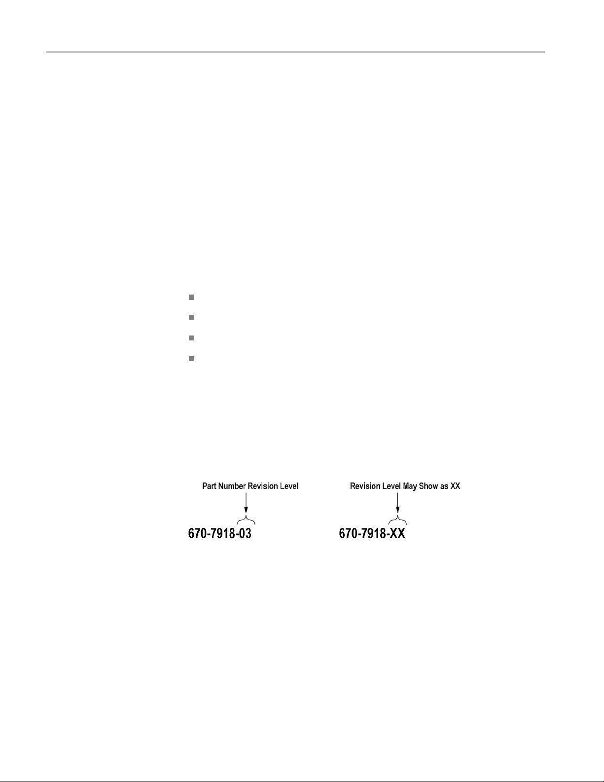
Part number (see Part Number Revision Level below)
Instrument type or model number
Part Number Revision
Level
Instrument serial number
Instrument modification number, if applicable
If you ord
local Tektronix field office or representative will contact you concerning any
change in part number.
Tektro
part. For most parts in this manual, you will find the letters XX in place of the
revision level number.
When you order parts, Tektronix will provide you with the most current part for
your product type, serial number, and modification (if applicable). At the time of
your
your product, based on the information you provide.
er a part that has been replaced with a different or improved part, your
nix part numbers contain two digits representing the revision level of the
order, Tektronix will determine the part number revision level needed for
22 TLA7S08 & TLA7S16 Serial Analyzer Technical Reference Manual
Page 37

Using the Replaceable Parts List
Thefollowingtabledescribeseachcolumn in the replaceable parts lists.
Table 6: Parts list column descriptions
Column number Column name Description
1
2 Tektronix part number Use this part number when
3 and 4
5
6
Figure & index number
Serial number Column 3 indicates the
Qty Quantity of parts used.
Name & description
Figure and index numbers
intheexplodedview
illustrations.
ordering replacement parts
from Tektronix.
serial number at which
the part was fi rst effective.
Column 4 indicates the
serial number at which the
part was discontinued. No
entries in either column
indicates the part is good for
all serial numbers.
An item name is separated
from the description by a
colon ( :). Because of space
limitations, an item name
may sometimes appear
incomplete. Use the U. S.
Federal Catalog Handbook
H6-1 for further item name
identification.
Parts List
Abbrev
iations
Abbreviations conform to American National Standard ANSI Y1.1-1972.
TLA7S08 & TLA7S16 Serial Analyzer Technical Reference Manual 23
Page 38

Parts List
Fig. &
index
number
Tektronix
part number
Serial no.
effective
Serial no.
discont’d Qty Name & description
5-1 348-1365-XX 2
5-2 200-5013-XX 1
5-3 211-0409-XX 8
5-4 348-1537-XX 6
5-5
5-5
5-6 386-7490-XX 1
441-2488-XX 1
441-2490-XX 1
SHLD GSKT, ELE
7.5 L , RIVIT MTG, SNAP-IN , RIVIT SPACING 1.5 INCH, BECU
COVER
SCR, ASSEM WSHR; 4-40 X 0.312, PNH, 410 SS PASSIVATED, T-10
TORX DR
GASKET, EMI; CLIP-ON, 1.98 L, BE CU, TIN PLATED, W/T LANCES
CHASSIS, ASSEMBLY, X16, MAIN, TLA7S16
CHASSIS, AS
BRACKET, END (TWO WIDE)
C; SYMETRICAL SLOTTED FINGER, 0.350 W X
SEMBLY; X8, MAIN, TLA7S08
Figure 5: TLA7S08 &TLA7S16 chassis and cover
24 TLA7S08 & TLA7S16 Serial Analyzer Technical Reference Manual
Page 39

Fig. &
index
number
Tektronix
part number
Serial no.
effective
Parts List
Serial no.
discont’d Qty Name & description
6-1 664-6142-XX 1
6-2 211-0409-X X 10
6-3 679-6219-XX 1
6-4 348-1866-XX 4
6-5 220-0272-XX 4
6-6 664-6181-XX 1
6-6 664-6336-X
6-7 129-1478-XX
X
CIRCUIT BD ASS
SCR, ASSEM WSHR; 4-40 X 0.312, PNH, 410 SS PASSIVATED, T-10
TORX DR
CIRCUIT BOARD ASSY; PROBE INTERFACE BD
GASKET, SHIELD
JACK, NUT, 4-
CIRCUIT BO ARD ASSEMBLY; TLA7S16 MODULE ACQUISITION
1
CIRCUIT BO ARD ASSEMBLY; TLA7S08 MO DULE; ACQ UISITION
5
SPACER, POS
4-40 INT THD X 6-32 EXTERNAL THD, NICKEL
Y; LPU BOARD, TESTED
40
T; 1.738 L, 1.113 SPACING, W/ 0.35 L, 0.25 HEX, W/
TLA7S08 & TLA7S16 Serial Analyzer Technical Reference Manual 25
Page 40

Parts List
Figure 6: TLA7S08 &TLA7S16 circuit board assemblies
26 TLA7S08 & TLA7S16 Serial Analyzer Technical Reference Manual
Page 41
Parts List
Fig. &
index
number
7-1 174-5366-X X 2
7-2 437-0520-X X 1
7-3 367-0483-X X 1
7-4 367-0484-X X 1
7-5
7-6 672-6285-X X 1
7-7
7-8 211-0372-XX 2
Tektronix
part
number
211-0409-XX 4
174-5392-X
Serial n o.
effective
X
Serial no.
discont’d Qty Name & description
CABLE ASSEMBL
FAN ASSY
HANDLE; INJECTOR/EJECTOR ASSEMBLY, TWO WIDE, W/KEYING,
SPRING LOADED, PLASTIC, 20% GLASS-FILLED SILVER GRAY
HANDLE; INJECTOR/EJECTOR ASSEMBLY, TWO WIDE, W/OUT
KEYING, SPRING LOADED, PLASTIC, 20% GLASS-FILLE D SILVER
GRAY
SCR, ASSEM WSHR; 4-40 X 0.312, PNH, 410 SS PASSIVATED, T-10
TORX DR
CIRCUIT BD ASSY; REFERENCE CLOCK FILTER BD W/CABLES
2
CABLE ASSEMBLY (REFERENCE CLOCK JUMPER)
SCREW, 4-4
Y, COAXIAL 50 OHM, MCX TO SMA
0, T-10 TORX DR
TLA7S08 & TLA7S16 Serial Analyzer Technical Reference Manual 27
Page 42

Parts List
Figure 7: TLA7S08 &TLA7S16 internal cables and connectors
28 TLA7S08 & TLA7S16 Serial Analyzer Technical Reference Manual
 Loading...