

Page 1

Service Manual
TLA7PG2
Pattern Generator and Probes
071-0714-01
This document applies to firmware version 1.00
and above.
Warning
The servicing instructions are for use by qualified
personnel only. To avoid personal injury, do not
perform any servicing unless you are qualified to
do so. Refer to all safety summaries prior to
performing service.
www.tektronix.com
Page 2

Copyright © Tektronix, Inc. All rights reserved. Licensed software products are owned by Tektronix or its suppliers and
are protected by United States copyright laws and international treaty provi sions.
Use, duplication, or disclosure by the Government is subject to restrictions as set forth in subparagraph (c)(1)(ii) of the
Rights in Technical Data and Computer Software clause at DFARS 252.227-7013, or subparagraphs (c)(1) and (2) of t he
Commercial Computer Software -- Restricted Rights clause at FAR 52.227-19, as applicable.
Tektronix products are covered by U.S. and foreign patents, issued and pending. Information i n this publication supercedes
that in all previously published material. Specifications and price change privi leges reserved.
Tektronix, Inc., 14200 SW Karl Braun Drive, Beaverton, OR 97077
TEKTRONIX and TEK are registered trademarks of Tektronix, Inc.
Page 3

WARRANTY
Tektronix warrants that this product will be free from defects in materials and workmanship for a period of one (1) year from
the date of shipment. If any such product proves defective during this warranty period, Tektronix, at its option, either will
repair the defective product without charge for parts and labor, or will provide a replacement in exchange for the defective
product.
In order to obtain service under this warranty, Customer must notify Tektronix of the defect before the expiration of the
warranty period and make suitable arrangements for the performance of service. Customer shall be responsible for packaging
and shipping the defective product to the service center designated by Tektronix, with shipping charges prepaid. Tektronix
shall pay for the return of the product to Customer if the shipment is to a location within the country in which the Tektronix
service center is located. Customer shall be responsible for paying all shipping charges, duties, taxes, and any other charges
for products returned to any other locations.
This warranty shall not apply to any defect, failure or damage caused by improper use or improper or inadequate maintenance
and care. Tektronix shall not be obligated to furnish service under this warranty a) to repair damage resulting from attempts
by personnel other than Tektronix representatives to install, repair or service the product; b) to repair damage resulting from
improper use or connection to incompatible equipment; or c) to service a product that has been modified or integrated with
other products when the effect of such modification or integration increases the time or difficulty of servicing the product.
THIS WARRANTY IS GIVEN BY TEKTRONIX WITH RESPECT TO THIS PRODUCT IN LIEU OF ANY
OTHER WARRANTIES, EXPRESSED OR IMPLIED. TEKTRONIX AND ITS VENDORS DISCLAIM ANY
IMPLIED WARRANTIES OF MERCHANTABILITY OR FITNESS FOR A PARTICULAR PURPOSE.
TEKTRONIX’ RESPONSIBILITY TO REPAIR OR REPLACE DEFECTIVE PRODUCTS IS THE SOLE AND
EXCLUSIVE REMEDY PROVIDED TO THE CUSTOMER FOR BREACH OF THIS WARRANTY. TEKTRONIX
AND ITS VENDORS WILL NOT BE LIABLE FOR ANY INDIRECT, SPECIAL, INCIDENTAL, OR
CONSEQUENTIAL DAMAGES IRRESPECTIVE OF WHETHER TEKTRONIX OR THE VENDOR HAS
ADVANCE NOTICE OF THE POSSIBILITY OF SUCH DAMAGES.
Page 4

Page 5

Table of Contents
Specifications
Operating Information
General Safety Summary xi...................................
Service Safety Summary xiii....................................
Preface xv...................................................
Manual Structure xv................................................
Manual Conventions xvi..............................................
Related Manuals xvi.................................................
Contacting Tektronix xvii.............................................
Introduction xix..............................................
Strategy for Servicing xix.............................................
Tektronix Service Offerings xx........................................
Product Description 1--1..............................................
Pattern Generator Module Characteristics 1--2.............................
Probe Characteristics 1--6.............................................
Pattern Generator Module Timing Diagrams 1--25...........................
P6470 and P6471 Probe Environmental Characteristics 1--27..................
Certifications 1--28...................................................
Installation 2--1.....................................................
Operating Environment 2--2...........................................
Applying and Interrupting Power 2--2....................................
Diagnostics 2--3.....................................................
Menus 2--5.........................................................
Online Help 2--5.....................................................
Setups 2--6.........................................................
P6475 Power On/Off Procedure 2--8.....................................
Merging Pattern Generator Modules 2--10.................................
Importing and Exporting Data 2--10......................................
Pattern Editing 2 --11..................................................
Theory of Operation
Module Overview 3--1................................................
Probe Overview 3--4.................................................
Performance Verification
Verification Summary 4--1.............................................
Equipment Required 4--5..............................................
P6475 Variable Probe Test Record 4--6...................................
Setup Procedures 4--7................................................
Functional Verification Procedures 4--13...........................
TLA7PG2 Functional Verification Procedures 4--14.........................
TLA7PG2 Pattern Generator Module Service Manual
i
Page 6

Table of Contents
Adjustment Procedures
Maintenance
P6470 Functional Verification Procedures 4--40.............................
P6471 Functional Verification Procedures 4--51.............................
P6472 Functional Verification Procedures 4--58.............................
P6473 Functional Verification Procedures 4--66.............................
P6474 Functional Verification Procedures 4--76.............................
P6475 Functional Verification Procedures 4--87.............................
Performance V erification Procedures 4--104.........................
TLA7PG2 Maximum Operating Frequency 4--105............................
P6475 Delay Accuracy Check 4--111......................................
Preparation 6--1.....................................................
Preventing ESD 6--1.................................................
Inspection and Cleaning 6--2...........................................
Removal and Installation Procedures 6--5.........................
Preparation 6--5.....................................................
Removal Procedures for the Pattern Generator 6--7.........................
Installation Procedures for Pattern Generator 6--12..........................
Removal Procedures for Standard Probes 6--13.............................
Removal Procedures for P6475 Variable Probe 6--19.........................
Troubleshooting 6--25...........................................
LEDs 6--25..........................................................
Troubleshooting Procedures 6--25........................................
Diagnostics 6--27.....................................................
Restoring and Reinstalling Software 6--29..........................
Restoring Software 6--29...............................................
Reinstalling Pattern Generator Application Software 6--30....................
Uninstalling Pattern Generator Application Software 6--30....................
Updating Module Firmware 6--31........................................
Repackaging 6--35..............................................
Repackaging Instructions 6--35..........................................
Options and Accessories
Pattern Generator Options 7--1.........................................
P6475 Options 7--1..................................................
Pattern Generator and Probe Optional Accessories 7--2......................
Pattern Generator Standard Accessories 7--2..............................
Probe Options 7--2...................................................
Probe Standard Accessories 7--2........................................
Replaceable Electrical Parts
Diagrams
Replaceable Mechanical Parts
Parts Ordering Information 10--1.........................................
Using the Replaceable Parts List 10--2....................................
ii
TLA7PG2 Pattern Generator Module Service Manual
Page 7

List of Figures
Table of Contents
Figure 1--1: Clock and strobe timing diagram 1--25..................
Figure 1--2: P6470, P6472, P6473, and P6474 inhibit
timing diagram 1--25............................................
Figure 1--3: P6470, P6472, P6473, and P6474 external
event for inhibit timing diagram 1--26.............................
Figure 1--4: External event for jump timing diagram 1--26............
Figure 1--5: External event for half channel advance
timing diagram 1--26............................................
Figure 1--6: External event for full channel advance
timing diagram 1--27............................................
Figure 1--7: External event for delay to data output for
advance diagram 1--27..........................................
Figure 4--1: Termination Board 4--12..............................
Figure 4--2: External Clock Input connections using a
P6470, P6471, P6472, P6473, or P6474 4--15........................
Figure 4--3: External Clock Input connections using a P6475 4--16.....
Figure 4--4: Internal Clock Frequency connections using
a P6470, P6471, P6472, P6473, or P6474 4--19.......................
Figure 4--5: Internal Clock Frequency connection using
a P6475 4--20..................................................
Figure 4--6: Merge operation connections using P6470,
P6471, P6472, P6473, or P6474 probes 4--24........................
Figure 4--7: Merge operation connections using P6475 probe 4--25.....
Figure 4--8: Merged and unmerged modules in the
Merge Modules window 4--27....................................
Figure 4--9: Timing Chart 4--28...................................
Figure 4--10: TLA7PG2 Deskew function connections
using a P6470, P6471, P6472. P6473, or P6474 4--29..................
Figure 4--11: TLA7PG2 Deskew function connections
using a P6475 probe 4--30........................................
Figure 4--12: TLA7PG2 Inhibit function (by data) connections
using a P6470, P6473, or P6474 probe 4--33.........................
Figure 4--13: TLA7PG2 Inhibit function (by data) connections
using a P6475 probe 4--33........................................
TLA7PG2 Pattern Generator Module Service Manual
iii
Page 8

Table of Contents
Figure 4--14: Inhibit function (by Event) connections
using a P6470, P6473, or P6474 4--36..............................
Figure 4--15: Inhibit function (by Event) connections
using a P6475 4--37.............................................
Figure 4--16: Internal Clock Frequency connections 4--41.............
Figure 4--17: Sequence and Data Output connections 4--44............
Figure 4--18: P6470 Sequence and Data sample waveforms 4--46.......
Figure 4--19: P6470 Sequence and Data strobed
sample waveforms 4--47.........................................
Figure 4--20: Inhibit function connections 4--48.....................
Figure 4--21: Internal Clock Frequency connections 4--51.............
Figure 4--22: Sequence and Data Output connections 4--54............
Figure 4--23: P6471 Sequence and Data sample waveforms 4--56.......
Figure 4--24: P6471 Sequence and Data strobed
sample waveforms 4--57.........................................
Figure 4--25: Internal Clock Frequency connections 4--59.............
Figure 4--26: Sequence and Data Output connections 4--62............
Figure 4--27: P6472 Sequence and Data sample waveforms 4--64.......
Figure 4--28: P6472 Sequence and Data strobed
sample waveforms 4--65.........................................
Figure 4--29: Internal Clock Frequency connections 4--66.............
Figure 4--30: Sequence and Data Output connections 4--69............
Figure 4--31: P6473 Sequence and Data sample waveforms 4--71.......
Figure 4--32: P6473 Sequence and Data strobed
sample waveforms 4--72.........................................
Figure 4--33: Inhibit function connections 4--74.....................
Figure 4--34: Internal Clock Frequency connections 4--77.............
Figure 4--35: Sequence and Data Output connections 4--80............
Figure 4--36: P6474 Sequence and Data sample waveforms 4--82.......
Figure 4--37: P6474 Sequence and Data strobed
sample waveforms 4--83.........................................
Figure 4--38: Inhibit function connections 4--85.....................
Figure 4--39: Internal Clock Frequency connections 4--88.............
Figure 4--40: Sequence and Data Output connections 4--90............
Figure 4--41: P6475 Sequence and Data sample waveforms 4--92.......
Figure 4--42: P6475 Sequence and Data strobed
sample waveforms 4--93.........................................
Figure 4--43: Inhibit function connections 4--94.....................
iv
TLA7PG2 Pattern Generator Module Service Manual
Page 9

Table of Contents
Figure 4--44: P6475 Data Output and CH6 Output
Mode connections 4--97..........................................
Figure 4--45: NRZ data format 4--99...............................
Figure 4--46: RZ data format 4--99................................
Figure 4--47: R1 data format 4--100.................................
Figure 4--48: OR logic 4--101......................................
Figure 4--49: AND logic 4--101.....................................
Figure 4--50: CH6 AND (NOT CH7) 4--102..........................
Figure 4--51: CH6 OR (NOT CH7 ) 4--103...........................
Figure 4--52: Maximum Operating Frequency Connections
using P6470, P6471, P6472, P6473, or P6474 (Example) 4--106..........
Figure 4--53: Maximum Operating Frequency Connections
using a P6475 probe 4--107........................................
Figure 4--54: Timing chart for the Maximum Operating
Frequency check 4--109..........................................
Figure 4--55: Delay Accuracy connections 4--111......................
Figure 6--1: Right cover 6--7.....................................
Figure 6--2: A50 PG board 6--8..................................
Figure 6--3: J1960 cable housing latch 6--9.........................
Figure 6--4: A20 and A50 fuse locations 6--10........................
Figure 6--5: Ejector assembly 6-- 11................................
Figure 6--6: Cushioning pad 6 --12.................................
Figure 6--7: Removing the standard probe cover 6--13................
Figure 6--8: P6470 series termination resistors 6--14..................
Figure 6--9: P6474 series termination resistors 6--15..................
Figure 6--10: P6472 PECL and LVPECL jumper position 6--15........
Figure 6--11: Fuse location for the P6470 and P6471 6--16.............
Figure 6--12: Removing the standard probe fan 6--18.................
Figure 6--13: Removing the P6475 cover 6--19.......................
Figure 6--14: Removing the P6475 fans 6--20........................
Figure 6--15: Disconnect power supply cables 6--21..................
Figure 6-- 16: Remove the power supply board 6--22..................
Figure 6--17: Troubleshooting procedure 6--26......................
Figure 6--18: Flash programming pins 6--31........................
TLA7PG2 Pattern Generator Module Service Manual
v
Page 10

Table of Contents
Figure 9--1: Function block diagram for the TLA7PG2
Pattern Generator 9--2.........................................
Figure 9--2: Function block diagram for P6470, P6471,
P6472, P6473, and P6474 probes 9--3.............................
Figure 9--3: Function block diagram for P6475 Probe 9--4............
Figure 9--4: Cable diagram for the TLA7PG2
pattern generator 9--5..........................................
Figure 9--5: Cable diagram for the P6475 probe 9--6................
Figure 10--1: TLA7PG2 chassis 10--6..............................
Figure 10--2: TLA7PG2 cables and fuses 10--8......................
Figure 10--3: P6470 probe chassis 10--10............................
Figure 10--4: P6471 probe chassis 10--12............................
Figure 10--5: P6472, P6473, and P6474 probe chassis 10--14............
Figure 10--6: P6475 variable probe chassis 10--16.....................
Figure 10--7: Cables for standard probes 10--17......................
Figure 10--8: Cables for P6475 variable probe 10--18..................
vi
TLA7PG2 Pattern Generator Module Service Manual
Page 11

List of Tables
Table of Contents
T able 1--1: PG module electrical characteristics,
operational mode 1--2.........................................
T able 1--2: PG module electrical characteristics,
output pattern 1-- 2............................................
T able 1--3: PG module, internal clock 1--3........................
Table 1--4: PG module, external clock input 1-- 3...................
T able 1--5: PG module, event processing 1--3......................
Table 1--6: PG module, intermodule interactions 1--4...............
T able 1--7: PG module, merged PG modules 1--4..................
Table 1--8: PG module, mechanical 1--4...........................
Table 1--9: P6470 TTL/CMOS probe 1-- 6.........................
Table 1--10: P6471 ECL probe 1--9..............................
Table 1--11: P6472 PECL/LVPECL probe 1--11.....................
Table 1--12: P6473 LVDS probe 1--12..............................
Table 1--13: P6474 LVCMOS probe 1--15..........................
Table 1--14: P6475 Variable probe 1--18...........................
Table 1--15: Power Supply (P6475 only) 1--23.......................
T able 1--16: Atmospherics 1--23..................................
Table 1--17: Dynamics characteristics (P6470, P6471,
P6472, P6473, and P6474) 1--23..................................
Table 1--18: Dynamics characteristics (P6475) 1--24..................
Table 1--19: Probe cables 1--24...................................
Table1--20:Twistedleadset 1--24...............................
Table 1--21: Certifications and compliances for P6475 1--25...........
Table 1--22: P6470 TTL/CMOS probe and P6471 ECL probe 1--27....
Table 1--23: Certifications and compliances 1--28....................
T able 4--1: Pattern generator module verification procedures 4--2.....
Table 4--2: Test equipment 4-- 5..................................
Table 4--3: Front panel indicators 4--8............................
Table 4--4: Extended Diagnostic test Items and
faulty component 4--10.........................................
T a b l e 4 -- 5 : D e l a y 4 -- 1 1 2..........................................
Table 6--1: Tools required for part removal 6--6....................
Table 6--2: P6470 series termination resistors 6--14..................
TLA7PG2 Pattern Generator Module Service Manual
vii
Page 12

Table of Contents
Table 6--3: P6472, P6473, P6474, and P6475 fuse descriptions 6--16....
Table 6--4: P6470 and P6471 fuse descriptions 6--17.................
T a b l e 6 -- 5 : L E D s 6 -- 2 5..........................................
Table 6--6: Restoring software 6--29..............................
Table 7--1: Optional accessories 7--2..............................
T able 7--2: Pattern generator standard accessories 7--2..............
T able 7--3: Probe standard accessories 7--3........................
viii
TLA7PG2 Pattern Generator Module Service Manual
Page 13

General Safety Summary
Review the following safety precautions to avoid injury and prevent damage to
this product or any products connected to it. To avoid potential hazards, use this
product only as specified.
Only qualified personnel should perform service procedures.
While using this product, you may need to access other parts of the system. Read
the General Safety Summary in other system manuals for warnings and cautions
related to operating the system.
ToAvoidFireor
Personal Injury
Use Proper Power Cord. Use only the power cord specified for this product and
certified for the country of use.
Ground the Product. These products (P6470, P6471, P6472, P6473, and P6474)
are indirectly grounded through the grounding conductor of the mainframe
power cord. The P6475 is directly grounded through the grounding conductor of
the probe power cord. To avoid electric shock, the grounding conductor must be
connected to earth ground. Before making connections to the input or output
terminals of the product, ensure that the product is properly grounded.
Observe All Terminal Ratings. To avoid fire or shock hazard, observe all ratings
and markings on the product. Consult the product manual for further ratings
information before making connections to the product.
Do Not Operate Without Covers. Do not operate this product with covers or panels
removed.
Use Proper Fuse. Use only the fuse type and rating specified for this product.
Avoid Exposed Circuitry. Do not touch exposed connections and components
when power is present.
Do Not Operate With Suspected Failures. If you suspect there is damage to this
product, have it inspected by qualified service personnel.
Do Not Operate in Wet/Damp Conditions.
Do Not Operate in an Explosive Atmosphere.
Keep Product Surfaces Clean and Dry.
Provide Proper Ventilation. Refer to the manual’s installation instructions for
details on installing the product so it has proper ventilation.
TLA7PG2 Pattern Generator Module Service Manual
ix
Page 14
General Safety Summary
Symbols and Terms
Terms in this Manual. These terms may appear in this manual:
WARNING. Warning statements identify conditions or practices that could result
in injury or loss of life.
CAUTION. Caution statements identify conditions or practices that could result in
damage to this product or other property.
Terms on the Product. These terms may appear on the product:
DANGER indicates an injury hazard immediately accessible as you read the
marking.
WARNING indicates an injury hazard not immediately accessible as you read the
marking.
CAUTION indicates a hazard to property including the product.
Symbols on the Product. The following symbols may appear on the product:
CAUTION
Refer to Manual
Protective Ground
(Earth) Terminal
x
TLA7PG2 Pattern Generator Module Service Manual
Page 15

Service Safety Summary
Only qualified personnel should perform service procedures. Read this Service
Safety Summary and the General Safety Summary before performing any service
procedures.
Do Not Service Alone. Do not perform internal service or adjustments of this
product unless another person capable of rendering first aid and resuscitation is
present.
Disconnect Power. To avoid electric shock, switch off the instrument power, then
disconnect the power cord from the mains power.
Use Care When Servicing With Power On. Dangerous voltages or currents may
exist in this product. Disconnect power, remove battery (if applicable), and
disconnect test leads before removing protective panels, soldering, or replacing
components.
To avoid electric shock, do not touch exposed connections.
TLA7PG2 Pattern Generator Module Service Manual
xi
Page 16

Service Safety Summary
xii
TLA7PG2 Pattern Generator Module Service Manual
Page 17

Preface
Manual Structure
This is the service manual for the TLA7PG2 Pattern Generator. The manual
contains information needed to service the pattern generator to the module level.
The following lists contains a brief description of each manual section.
H The Specifications contains a description and a list of the characteristics of
the pattern generator and pattern generator probes.
H The Operating Information includes general information and operating
instructions at the level needed to safely power on and service the pattern
generator.
H The Theory of Operation contains circuit descriptions that support general
service to the module level.
H The Performance Verification contains procedures to verify the functional
operation of the pattern generator and modules as well as procedures to
verify the performance to advertised specifications.
H The Adjustment Procedures normally lists procedures to adjust the instru-
ment to meet advertised specifications. At this printing, there are no
adjustment procedures required for the pattern generator module.
H The Maintenance contains information and procedures for performing
preventive and corrective maintenance of the pattern generator module.
These instructions include cleaning and fault isolation to the module.
H The Options contains information about options and accessories that are
available for the instrument.
H The Replaceable Electrical Parts contains a statement referring you to the
Mechanical Parts List, where both electrical and mechanical parts are listed.
H The Diagrams contains block diagrams and cabling diagrams that are useful
in isolating failed components.
H The Replaceable Mechanical Parts includes a table of all replaceable parts,
their descriptions, and their Tektronix part numbers.
TLA7PG2 Pattern Generator Module Service Manual
xiii
Page 18

Preface
Manual Conventions
This manual uses certain conventions that you should become familiar with
before doing service.
Some sections of the manual contain procedures for you to perform. To keep
these instructions clear and consistent, this manual uses the following conventions:
H Names of front-panel controls and menus appear in the same case (initial
capitals, all uppercase, and so on.) in the manual as they appear on the
TLA7PG2 Pattern Generator front panel and menus.
H Instruction steps are numbered, unless there is only one step.
H An arrow placed after a menu title directs you to access the indicated
submenu. For example, System → System Configuration is directing you to
select the System menu and then select the submenu named System
Configuration.
Related Manuals
Other documentation for the TLA7PG2 Pattern Generator include:
H The Tektronix Logic Analyzer Family User Manual contains specifications
and information on how to use the TLA7PG2 Pattern Generator.
H A series of probe manuals that provide information for using the probes the
the TLA7PG2 Pattern Generator.
xiv
TLA7PG2 Pattern Generator Module Service Manual
Page 19

Contacting Tektronix
Preface
Phone 1-800-833-9200*
Address Tektronix, Inc.
Department or name (if known)
14200 SW Karl Braun Drive
P.O. Box 500
Beaverton, OR 97077
USA
Web site www.tektronix.com
Sales support 1-800-833-9200, select option 1*
Service support 1-800-833-9200, select option 2*
Technical support Email: techsupport@tektronix.com
1-800-833-9200, select option 3*
1-503-627-2400
6:00 a.m. -- 5:00 p.m. Pacific time
* This phone number is toll free in North America. After office hours, please leave a
voice mail message.
Outside North America, contact a Tektronix sales office or distributor; see the
Tektronix web site for a list of offices.
TLA7PG2 Pattern Generator Module Service Manual
xv
Page 20

Preface
xvi
TLA7PG2 Pattern Generator Module Service Manual
Page 21

Introduction
Strategy for Servicing
This manual contains information needed to service the TLA7PG2 Pattern
Generator, as well as general information critical to safe and effective servicing.
To prevent personal injury or damage to the pattern generator, consider the
following before attempting service:
H The procedures in this manual should be performed only by a qualified
service person.
H Read the General Safety Summary and the Service Safety Summary, near the
beginning of this manual.
H Read Preparation for Use in the Operating Instructions section.
To isolate a failure to a module, use the fault isolation procedures found in
Troubleshooting in the Maintenance chapter of this manual. To move and replace
any failed module, follow the instructions in Removal and Installation Proce-
dures,alsopartoftheMaintenance chapter of this manual. After isolating a
faulty module, replace it with a fully-tested module obtained from the factory.
The Replaceable Mechanical Parts section contains part number and ordering
information for all replaceable modules.
TLA7PG2 Pattern Generator Module Service Manual
xvii
Page 22

Introduction
Tektronix Service Offerings
Tektronix provides service to cover repair under warranty as well as other
services that may provide a cost-effective answer to your service needs.
Whether providing warranty repair service or any of the other services listed
below, Tektronix service technicians are well equipped to service the TLA7PG2
Pattern Generator. Tektronix technicians train on Tektronix products; they have
access to the latest information on improvements to the TLA7PG2 Pattern
Generator as well as the latest new options.
Warranty Repair Service
Self Service
Tektronix warrants this product for one year from the date of purchase. (The
warranty is listed in the front of this manual.) Tektronix technicians provide
warranty service at most Tektronix service locations worldwide. The Tektronix
product catalog lists all service locations worldwide.
Tektronix supports repair to the module level by providing Module Exchange.
Module Exchange. This service reduces down-time for repair by allowing you to
exchange most modules for remanufactured ones. Tektronix ships an updated
tested exchange module from the Beaverton, Oregon service center, typically
within 24 hours. Each module comes with a 90-day service warranty.
xviii
TLA7PG2 Pattern Generator Module Service Manual
Page 23

Specifications
Product Description
This chapter provides a high-level description of the TLA7PG2 Pattern
Generator module and the associated pattern generator probes. It also lists the
specifications for the modules and probes.
The TLA7PG2 Pattern Generator is a 64-channel, programmable pattern
generator module with sequential control that plugs into the TLA700 series
mainframes, and is intended for use as an integral component of the Tektronix
Logic Analyzer Family series of products.
The pattern generator module provides multichannel signals for use in applications, such as simulation of missing system elements, erroneous signals for stress
testing, or extended analysis for simulating a device under test.
You can put circuits in a desired state and operate the pattern generator at full
speed or single step it through a series of states. The TLA7PG2 Pattern
Generator can also generate infrequently encountered test conditions to test a
hardware design or software program for robustness.
The TLA7PG2 Pattern Generator supports the following probes:
H P6470 TTL/CMOS
H P6471 ECL
H P6472 PECL/LVPECL
H P6473 LVDS
H P6474 LVCMOS
H P6475 Variable
You can have up to four probes on each pattern generator.
Following are some of the key features of the TLA7PG2 Pattern Generator:
H Provides up to 64 channels
H Offers a Jump If condition for all data blocks (maximum of 4000) up to
clock rates of 268 MHz
The TLA7PG2 Pattern Generator can fully test circuits at real clock speeds,
without having to use improvised setups.
TLA7PG2 Pattern Generator Module Service Manual
1- 1
Page 24
Specifications
Pattern Generator Module Characteristics
All specifications are guaranteed unless noted Typical. Typical characteristics
describe typical or average performance and provide useful reference information.
Specifications that are marked with the n symbol are checked directly (or
indirectly) in the Performance Verifications chapter of this manual.
The specifications apply to all versions of the pattern generator unless otherwise
noted.
The performance limits in this specification are valid with these conditions:
H The modules must be installed in a Tektronix Logic Analyzer Mainframe.
H The module must have had at least a 30 minute warm-up period.
Table 1- 1: PG module electrical characteristics, operational mode
Characteristic Description
Normal Pattern data output is synchronized by the internal/external clock input
Step Pattern data output is synchronized by the software command
Table 1- 2: PG module electrical characteristics, output pattern
Characteristic Description
n Maximum Operating Clock Frequency 134 MHz in Full Channel Mode
268 MHz in Half Channel Mode
Pattern length 40 to 262,140 (218-- 4) in Full Channel Mode (standard)
80 to 524,280 (2
40 to 1,048,572 (2
80 to 2,097,144 (2
Number of channels 64 channels in Full Channel Mode
32 channels in Half Channel Mode
The pattern memory for the following data channel will be shared with strobe
control/internal inhibit control
Probe D data output channel Control
D0:0 STRB0
D0:1 STRB1
19
-- 8) in Half Channel Mode (standard)
20
-- 4) in Full Channel Mode (option 1M or PowerFlex upgrade)
21
-- 8) in Half Channel Mode (option1M or PowerFlex upgrade)
1- 2
D0:2 STRB2
D0:3 STRB3
D0:4 Inhibit probe A
TLA7PG2 Pattern Generator Module Service Manual
Page 25

Table 1- 2: PG module electrical characteristics, output pattern (Cont.)
Characteristic Description
D0:5 Inhibit probe B
D0:6 Inhibit probe C
D0:7 Inhibit probe D
Sequences Maximum 4,000
Number of Blocks Maximum 4,000
Number of Sub-Sequences Maximum 50
Sub-Sequences Maximum 256 steps
Repeat Count 1 to 65,536 or infinite
Table 1- 3: PG module, internal clock
Specifications
Characteristic Description
Clock Period 2.0000000 s to 7.4626865 ns in Full Channel Mode
1.0000000 s to 3.7313432 ns in Half Channel Mode
Period Resolution 8 digits
Table 1- 4: PG module, external clock input
Characteristic Description
Clock Rate DC to 134 MHz in Full Channel Mode
DC to 268 MHz in Half Channel Mode
Polarity Normal or Invert
Threshold
Range --2.56 V to +2.54 V
Resolution 20 mV
Input Impedance 1kΩ terminated to GND
Sensitivity 500 mV
p-p
Table 1- 5: PG module, event processing
Characteristic Description
Event Action Advance, Jump and Inhibit
Number of Event Inputs 8 External Event Inputs (2 per each probe)
TLA7PG2 Pattern Generator Module Service Manual
1- 3
Page 26
Specifications
Table 1- 5: PG module, event processing (Cont.)
Characteristic Description
Number of Event Definitions 8
(A maximum of 256 event input patterns can be OR’d to define an event)
Event Mode
for Advance Edge or Level
for Jump Edge or Level
Event Filter None or 50 ns
Table 1- 6: PG module, intermodule interactions
Characteristic Description
Signal Input Input from backplane
Selectable from Signal 1, 2, 3, and 4
Used to define the Event
Signal Output Output to backplane
Selectable from Signal 1, 2, 3, and 4
Specified as High or Low in each Sequence line
Table 1- 7: PG module, merged PG modules
Characteristic Description
Number of modules that can be merged
together
External Event Input for merged module For Jump and Advance, only the External Event Input of the leftmost module is used;
5
for Inhibit, each module uses its own External Event Input as a source
Table 1- 8: PG module, mechanical
Characteristic Description
Slot width Requires 2 mainframe slots
Weight
(Typical)
Overall dimensions (excluding connectors)
Height 10.32 in (262 mm)
Width 2.39 in (61 mm)
2.5kg(5lbs4oz)
1- 4
TLA7PG2 Pattern Generator Module Service Manual
Page 27

Table 1- 8: PG module, mechanical (Cont.)
Characteristic Description
Depth 14.7 in (373 mm)
Mainframe interlock 1.4 ECI keying is implemented
Specifications
TLA7PG2 Pattern Generator Module Service Manual
1- 5
Page 28
Specifications
loa
d:10k
Ω+1
5pf,sampl
att
8
Probe Characteristics
Table 1- 9: P6470 TTL/CMOS probe
All specifications are guaranteed unless noted Typical. Typical characteristics
describe typical or average performance and provide useful reference information.
Specifications that are marked with the n symbol are checked directly (or
indirectly) in the Performance Verifications chapter of this manual.
The specifications apply to all versions of the pattern generator probes unless
otherwise noted.
The performance limits in this specification are valid with these conditions:
H The probes must be installed in a TLA7PG2 Pattern Generator.
H The probes must have had at least a 30 minute warm-up period.
All timing values are specified at the probe connector under the conditions listed below, unless otherwise noted:
Output Voltage setting: +5 V
Series Termination Resistor: 75 Ω
Load: 510 Ω +50pF
Characteristic
Maximum Clock Frequency
(with series termination resistor: 75 Ω)
Maximum Clock Frequency
(with series termination resistor: 75 Ω,
eoutputp
bit counter)
Typical
Output Level (VCC) 2.0Vto5.5V,25mVstep,into1MΩ
Maximum Resistive Load 220 Ω
Maximum Capacitive Load 50 pF
Output Type 74LVC541A for Data Output
Series Termination Resistor 75 Ω standard. 43, 100 and 150 Ω as optional accessories
ern:
Description
Output Level (Vcc) Full Channel mode Half Channel mode
Vcc ≤ 3.3 V
3.3 V < Vcc ≤5V 62.5 MHz 125 MHz
Vcc > 5 V 52.5 MHz 105 MHz
Output Level (Vcc) Full Channel mode Half Channel mode
Vcc ≤5.5 V
74LVC244A for Clock/Strobe Output
(18 pin DIP socket)
134 MHz 268 MHz
134 MHz 268 MHz
Supported Channel Mode Half and Full
Number of External Inhibit Inputs 1
1- 6
TLA7PG2 Pattern Generator Module Service Manual
Page 29
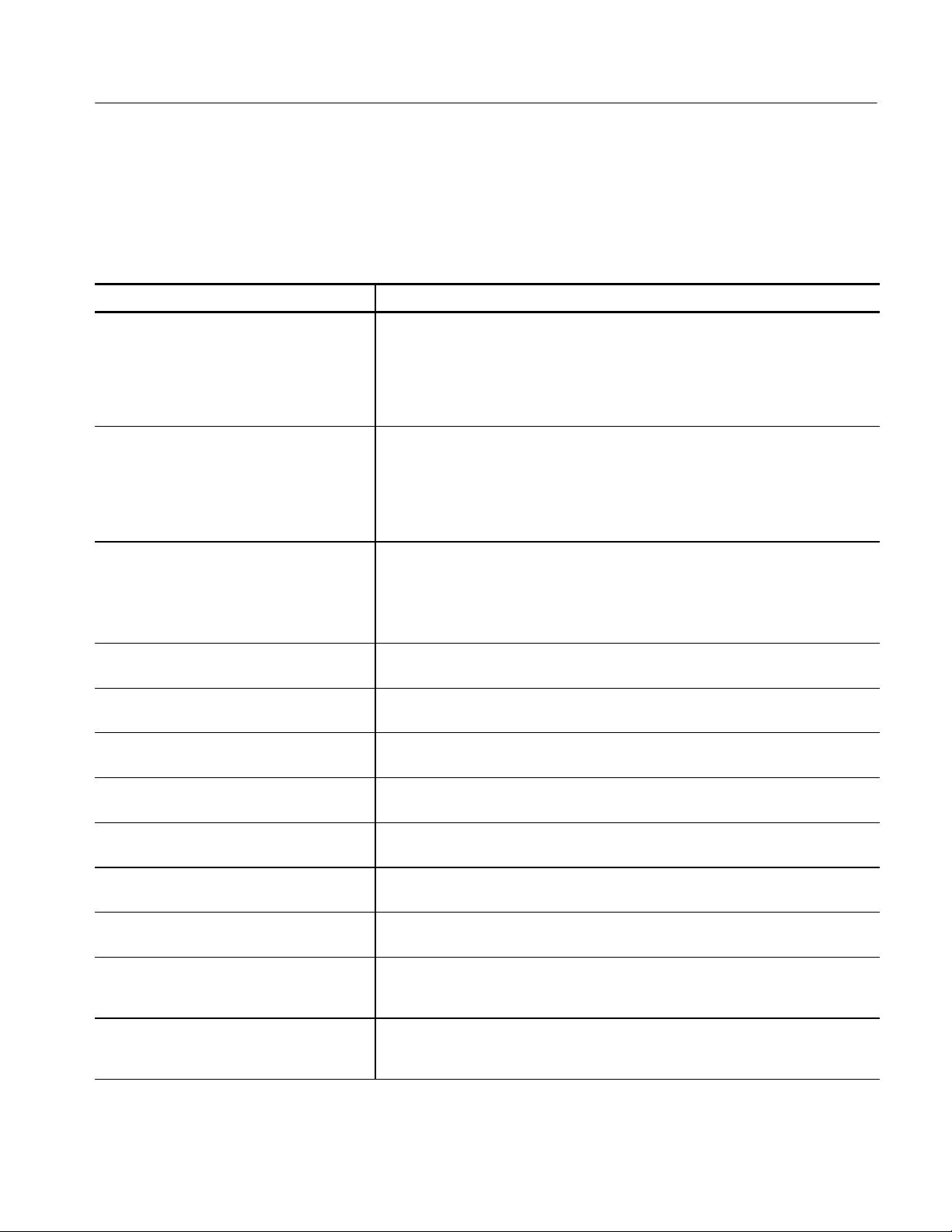
Table 1- 9: P6470 TTL/CMOS probe (Cont.)
All timing values are specified at the probe connector under the conditions listed below, unless otherwise noted:
Output Voltage setting: +5 V
Series Termination Resistor: 75 Ω
Load: 510 Ω +50pF
Characteristic Description
Rise/Fall Time
(20% to 80%
load: 1 MΩ +< 1 pF)
Typical
Clock/Strobe Output
Rise 640 ps
Fall 1.1 ns
Data Output
Rise 680 ps
Fall 2.9 ns
Specifications
Rise/Fall Time
(20% to 80%
load: 510 Ω +51pF)
Typical
Data Output Skew
Typical
Data Output to Strobe Output Delay
Typical
Data Output to Clock Output Delay
Typical
External Clock Input to Clock Output Delay
Typical
External Inhibit Input to Output Enable Delay
Typical
External Inhibit Input to Output Disable Delay
Typical
Probe D Data Output to Output Enable Delay
(for Internal Inhibit) Typical
Clock/Strobe Output
Rise 6.5 ns
Fall 6.3 ns
Data Output
Rise 5.2 ns
Fall 4.5 ns
< 570 ps between all data output pins of all modules in the mainframe after
intermodule skew is adjusted manually
< 480 ps between all data output pins of all probes of single module
< 440 ps between all data output pins of single probe
+ 1.7 ns when strobe delay set to zero. (Td3 in Figure 1--1 on page 1--25)
+2.4 ns (Td2 in Figure 1--1 on page 1--25)
61 ns (Td1 in Figure 1--1 on page 1--25)
34 ns for Data Output (Td4 in Figure 1--2 on page 1--25)
86 ns for Data Output (Td5 in Figure 1--2 on page 1--25)
7 ns for Data Output (Td4 in Figure 1--2 on page 1--25)
Probe D Data Output to Output Disable Delay
(for Internal Inhibit) Typical
External Event Input to Clock Output Setup
(for inhibit)
(event-filter: off) Typical
External Event Input and Inhibit Input
Input Type
Minimum Pulse Width
8 ns for Data Output (Td5 in Figure 1--2 on page 1--25)
Full channel mode: 1.5 clocks + 240 ns (Td6 in Figure 1--3 on page 1--25)
Half channel mode: 2 clocks + 240 ns
74LVC14A, Positive True, 1 kΩ to GND
200 ns (event filter: off)
TLA7PG2 Pattern Generator Module Service Manual
1- 7
Page 30

Specifications
Table 1- 9: P6470 TTL/CMOS probe (Cont.)
All timing values are specified at the probe connector under the conditions listed below, unless otherwise noted:
Output Voltage setting: +5 V
Series Termination Resistor: 75 Ω
Load: 510 Ω +50pF
Characteristic Description
External Event Input Delay to Data Output for
Advance
External Event Input
Number of Inputs
Setup Time of Event Typical
Input for Event Jump
230 ns to 330 ns + 1.5 to 2.5 CLK2 (Td12 in Figure 1--7 on page 1--27)
(CLK2 is from 2.5 ns to 5 ns when Internal Clock is used. It is the same as one clock
period when the External Clock is used.)
2
Half Channel Mode
54 to 61 clocks + 240 ns before the next block
Full Channel Mode
27.5 to 31 clocks + 240 ns before the next block
(Td9 in Figure 1--4 on page 1--26)
Setup Time of Event Input for Event Advance
Typical
Mainframe External Signal Input to PG Probe
data output
for Advance
via Signal 1, 2 Typical
via Signal 3, 4 Typical
for Inhibit
via Signal 1, 2 Typical
via Signal 3, 4 Typical
PG Probe Clock Output to Mainframe External
Signal Output
via Signal 1, 2 Typical
via Signal 3, 4 Typical
Number of Data Outputs 16 in Full Channel Mode
In Half Channel Mode, 240 ns before the rising edge of 5th clock output pulse from
the last of the previous block (Td10 in Figure 1--5 on page 1--26)
In Full Channel Mode, 240 ns before the rising edge of 3rd clock output pulse from the
last of the previous block (Td11 in Figure 1--6 on page 1--27)
200 ns to 300 ns + 1.5 to 2.5 CLK2
230 ns to 330 ns + 1.5 to 2.5 CLK2
(CLK2 is from 2.5 ns to 5 ns when the Internal Clock is used. It is the same as one
clock period when the External Clock is used)
100 ns to 200 ns + 2 to 3 CLK (Half Channel Mode)
100 ns to 200 ns + 1.5 to 2.5 CLK (Full Channel Mode)
130 ns to 230 ns+ 2 to 3 CLK (Half Channel Mode)
130 ns to 230 ns + 1.5 to 2.5 CLK (Full Channel Mode)
18 ns -- 5 CLK (Half Channel Mode)
18 ns -- 3 CLK (Full Channel Mode)
29 ns -- 5 CLK (Half Channel Mode)
29 ns -- 3 CLK (Full Channel Mode)
8 in Half Channel Mode
Number of Clock Outputs 1
Number of Strobe Outputs 1
Number of External Event Inputs 2
1- 8
(Only one Clock Output or Strobe Output can be enabled at one time per probe)
TLA7PG2 Pattern Generator Module Service Manual
Page 31
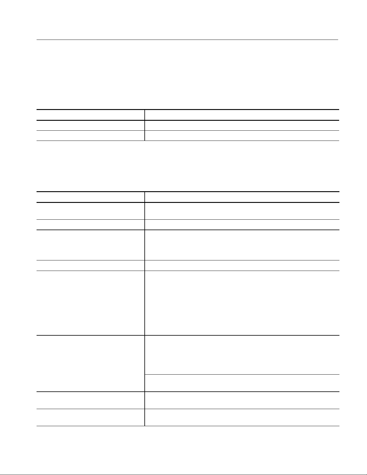
Table 1- 9: P6470 TTL/CMOS probe (Cont.)
All timing values are specified at the probe connector under the conditions listed below, unless otherwise noted:
Output Voltage setting: +5 V
Series Termination Resistor: 75 Ω
Load: 510 Ω +50pF
Characteristic Description
Clock Output Polarity Positive
Strobe Type RZ only
Table 1- 10: P6471 ECL probe
All timing values are specified at the probe connector under the condition listed below, unless otherwise noted:
Load: 51 Ω terminated to --2 V
Specifications
Characteristic
Maximum Clock Frequency 134 MHz in Full Channel mode
Output Level ECL
Output Type 100E151 for data output
Supported Channel Mode Half and Full
Rise/Fall Time
(20% to 80%) Typical
Data Output Skew Typical < 255 ps between all data output pins of all modules in the mainframe after
Description
268 MHz in Half Channel mode
100EL16 for strobe output
100EL04 for clock output
outputs are unterminated
Clock Output
Rise 320 ps
Fall 330 ps
Data Output
Rise 1,200 ps
Fall 710 ps
Strobe Output
Rise 290 ps
Fall 270 ps
intermodule skew is adjusted manually
< 240 ps between all data output pins of all probes of single module
< 210 ps between all data output pins of a single probe
Data Output to Strobe Output Delay
Typical
Data Output to Clock Output Delay
Typical
External Clock Input to Clock Output Delay
Typical
+2.94 ns when strobe delay set to zero (Td3 in Figure 1--1 on page 1--25)
+780 ps (Td2 in Figure 1--1 on page 1--25)
50 ns (Td1 in Figure 1--1 on page 1--25)
TLA7PG2 Pattern Generator Module Service Manual
1- 9
Page 32

Specifications
Table 1- 10: P6471 ECL probe (Cont.)
All timing values are specified at the probe connector under the condition listed below, unless otherwise noted:
Load: 51 Ω terminated to --2 V
Characteristic Description
External Event Input Delay to Data Output for
Advance
External Event Input
Input Level
Input Type
Minimum Pulse Width
External Event Input
Number of Inputs
Setup Time of Event
Input for Event Jump
Typical
170 ns to 270 ns + 1.5 to 2.5 CLK2 (Td12 in Figure 1--7 on page 1--27)
(CLK2 is from 2.5 ns to 5 ns when Internal Clock is used. It is the same as one clock
period when the External Clock is used.)
ECL
10H116with75kΩ to --2 V
150 ns (Event filter: off)
2
Half Channel Mode, 54 to 61 clocks + 180 ns before the next block
Full Channel Mode, 27.5 to 31 clocks + 180 ns before the next block (Td9 in
Figure 1--4 on page 1--26)
Setup Time of Event
Input for Event Advance
Typical
Mainframe External Signal Input to PG Probe
data output
for Advance
via Signal 1, 2 Typical
via Signal 3, 4 Typical
PG Probe Clock Output to Mainframe External
Signal Output
via Signal 1, 2 Typical
via Signal 3, 4 Typical
Number of Data Outputs 16 in Full Channel Mode
Number of Clock Outputs 1
Number of Strobe Outputs 1
Half Channel Mode:
80 ns before the rising edge of 5th clock output pulse from the last of the
previous block (Td10 in Figure 1--5 on page 1--26)
Full Channel Mode
80 ns before the rising edge of 3rd clock output pulse from the last of the
previous block (Td11 in Figure 1--6 on page 1--27)
200 ns to 300 ns + 1.5 to 2.5 CLK2
230 ns to 330 ns + 1.5 to 2.5 CLK2
(CLK2 from 2.5 ns to 5 ns when Internal Clock is used. It is same as one clock period
when External Clock is used.)
28 ns -- 5 CLK (Half Channel Mode)
28 ns -- 3 CLK (Full Channel Mode)
38 ns -- 5 CLK (Half Channel Mode)
38 ns -- 3 CLK (Full Channel Mode)
8 in Half Channel Mode
(Only one Clock Output or one Strobe Output can be enabled at one time per probe)
Number of External Event Inputs 2
Clock Output Polarity Positive
Strobe Type RZ only
1- 10
TLA7PG2 Pattern Generator Module Service Manual
Page 33

Table 1- 11: P6472 PECL/LVPECL probe
q
y
All timing values are specified with a load condition of 1 M Ω + ≤ 1 pF with PECL mode.
Specifications
Characteristic
Maximum Clock Frequency Full Channel Mode Half Channel Mode
Number of Data Outputs 8 Full Channel
Number of Clock Outputs 1 differential
Number of Strobe Outputs 1 differential
Number of External Event Inputs 2
Clock Output Polarity Positive
Strobe Type RZ (return to zero) only
Strobe Delay Zero or Trailing Edge
Output Level PECL, LVPECL (selectable by moving a jumper in the probe)
Output Type 100EL90 (all outputs are terminated)
Supported Channel Mode Half and Full
Rise/Fall Time (20% to 80%) Rise 430 ps
Data Output Skew < 385 ps between all data output pins of all modules in the mainframe after
Description
134 MHz 268 MHz
8 Half Channel
(Only one Clock Output or one Strobe Output can be enabled at one time per probe)
Fall 970 ps
intermodule skew is adjusted manually
< 370 ps between all data output pins of all probes of single module
< 340 ps between all data output pins of a single probe
Data Output to Strobe Output Delay + 2.93 ns when strobe delay is set to zero (See Td3 in Figure 1--1 on page 1--25)
Data Output to Clock Output Delay + 1.12 ns (Td2 in Figure 1--1 on page 1--25)
External Clock Input to Clock Output Delay 50 ns (See Td1 in Figure 1 --1 on page 1--25)
External Event Input Delay to Data Output for
Advance
External Event Input
Input Level
Input Type
Minimum Pulse Width (event filter: off)
170 ns to 270 ns + 1.5 to 2.5 CLK2 (Td12 in Figure 1--7 on page 1--27)
(CLK2 is from 2.5 ns to 5 ns when Internal Clock is used. It is the same as one clock
period when the External Clock is used.)
PECL, LVPECL (selectable by moving a jumper in the probe)
100EL91, unterminated
150 ns
TLA7PG2 Pattern Generator Module Service Manual
1- 11
Page 34

Specifications
Usingsignal1or2
q
y
Table 1- 11: P6472 PECL/LVPECL probe (Cont.)
All timing values are specified with a load condition of 1 M Ω + ≤ 1 pF with PECL mode.
Characteristic Description
External Event Input
Setup Time of Event Input for Event
Jump
Setup Time of Event Input for Event Advance Half Channel Mode: 180 ns before the rising edge of the 5th clock output pulse from
Mainframe External Signal Input to PG Probe
Data Output
For Advance:
Using signal 3 or 4
PG Probe Clock Output to Mainframe External
Signal Output
Using signal 1 or 2
Half Channel Mode: 54 to 61 Clocks + 180 ns before the next block
Full Channel Mode: 27.5 to 31 Clocks + 180 ns before the next block
(see Td9 in Figure 1--4 on page 1--26)
the last of the previous block (See Td10 in Figure 1--5 on page 1--26)
Full Channel Mode: 180 ns before the rising edge of the 3rd clock output pulse from
the last of the previous block (see Td11 in Figure 1--6 on page 1--27)
200 ns to 300 ns + 1.5 to 2.5 CLK2
230 ns to 330 ns + 1.5 to 2.5 CLK2
(CLK2 is from 2.5 ns to 5 ns when Internal Clock is used. It is the same as one clock
period when the External Clock is used.)
31 ns --5 CLK (Half Channel Mode)
31 ns --3 CLK (Full Channel Mode)
Using signal 3 or 4
40 ns --5 CLK (Half Channel Mode)
40 ns --3 CLK (Full Channel Mode)
Table 1- 12: P6473 LVDS probe
All timing values are specified at the probe connector under the condition listed below, unless otherwise noted:
Load: 100 Ω +<1pF
Characteristic
Maximum Clock Frequency Full Channel Mode Half Channel Mode
Number of Data Outputs 16 Full Channel
1- 12
Description
134 MHz 268 MHz
8 Half Channel
TLA7PG2 Pattern Generator Module Service Manual
Page 35

Specifications
Table 1- 12: P6473 LVDS probe (Cont.)
All timing values are specified at the probe connector under the condition listed below, unless otherwise noted:
Load: 100 Ω +<1pF
Characteristic Description
Number of Clock Outputs 1 (Only one Clock Output or One Strobe Output can be enabled at one time per
probe.)
Number of Strobe Outputs 1 (Only one Clock Output or One Strobe Output can be enabled at one time per
probe.)
Number of External Event Inputs 1
Number of External Inhibit Inputs 1
Clock Output Polarity Positive
Strobe Type RZ (return to zero) only
Strobe Delay Zero or Trailing Edge
Maximum Capacitive Load 10 pF
Output Type LVDS (TIA/EIA--644 compatible)
Supported Channel Mode Half and Full
Rise/Fall Time
Rise: 910 ps
(20% to 80%)
Data Output Skew < 365 ps between all data output pins of all modules in the mainframe after
Data Output to Strobe Output Delay --280 ns when strobe delay is set to zero (See Td3 in Figure 1--1 on page 1--25)
Data Output to Clock Output Delay 1.2 ns (Td2 in Figure 1--1 on page 1--25)
External Clock Input to Clock Output Delay 55 ns (See Td1 in Figure 1 --1 on page 1--25 )
External Inhibit Input to Output Enable Delay 9 ns for Data Output (See Td4 in Figure 1--2 on page 1--25)
External Inhibit Input to Output Disable Delay 12 ns for Data Output (See Td5 in Figure 1--2 on page 1--25)
Probe D Data Output to Output Enable Delay
(for Internal Inhibit)
Probe D Data Output to Output Disable Delay
(for Internal Inhibit)
External Event Input to Clock Output Setup
(for inhibit) event-filter: off
External Event Input Delay to Data Output for
Advance
Fall: 750 ps
intermodule skew is adjusted manually
< 350 ps between all data output pins of all probes of single module
< 320 ps between all data output pins of a single probe
2 ns for Data Output (See Td4 in Figure 1--2 on page 1--25)
5 ns for Data Output (See Td5 in Figure 1--2 on page 1--25)
Full Channel mode: 1.5 Clocks + 180 ns
Half Channel mode: 2 Clocks + 180 ns
(See Td6 in Figure 1--3 on page 1--26)
170 ns to 270 ns + 1.5 to 2.5 CLK2 (Td12 in Figure 1--7 on page 1--27)
(CLK2 is from 2.5 ns to 5 ns when Internal Clock is used. It is the same as one clock
period when the External Clock is used.)
TLA7PG2 Pattern Generator Module Service Manual
1- 13
Page 36

Specifications
Table 1- 12: P6473 LVDS probe (Cont.)
All timing values are specified at the probe connector under the condition listed below, unless otherwise noted:
Load: 100 Ω +<1pF
Characteristic Description
External Event Input and Inhibit Input
Input Type
Minimum Pulse Width (event filter: off)
External Event Input Setup Time of Event
Input for Event Jump
External Event Input Setup Time for Event
Advance
Mainframe External Signal Input to PG Probe
Data Output
For Advance:
Using signal 1 or 2
Using signal 3 or 4
For Inhibit:
LVDS (TIA/EIA--644 compatible), positive true
150 ns
Half Channel Mode: 54 to 61 Clocks + 180 ns before the next block
Full Channel Mode: 27.5 to 31 Clocks + 180 ns before the next block
(See Td9 in Figure 1--4 on page 1--26)
Half Channel Mode: 180 ns before the rising edge of the 5th clock output pulse from
the last of the previous block (See Td10 in Figure 1--5 on page 1--26)
Full Channel Mode: 180 ns before the rising edge of the 3rd clock output pulse from
the last of the previous block (See Td11 in Figure 1--6 on page 1--27)
200 ns to 300 ns + 1.5 to 2.5 CLK2
230 ns to 330 ns + 1.5 to 2.5 CLK2
(CLK2 is from 2.5 ns to 5 ns when Internal Clock is used. It is the same as one clock
period when the External Clock is used.)
Using signal 1 or 2
Using signal 3 or 4
PG Probe Clock Output to Mainframe External
Signal Output
Using signal 1 or 2
Using signal 3 or 4
1- 14
100 ns to 200 ns + 2 to 3 CLK (Half Channel Mode)
100 ns to 200 ns +1.5 to 2.5 CLK (Full Channel Mode)
130 ns 230 ns + 2 to 3 CLK (Half Channel Mode)
130 ns to 230 ns + 1.5 to 2.5 CLK (Full Channel Mode)
26 ns --5 CLK (Half Channel Mode)
26 ns --3 CLK (Full Channel Mode)
35 ns --5 CLK (Half Channel Mode)
35 ns --3 CLK (Full Channel Mode)
TLA7PG2 Pattern Generator Module Service Manual
Page 37

Table 1- 13: P6474 LVCMOS probe
q
y
All timing values are specified at the probe connector under the conditions listed below, unless otherwise noted:
Output Voltage setting: +3.3 V
Series Termination Resistor: 75 Ω
Load: 510 Ω+20pF
Specifications
Characteristic
Maximum Clock Frequency Full Channel Mode Half Channel Mode
Number of Data Outputs 16 Full Channel
Number of Clock Outputs 1 (Only one Clock Output or One Strobe Output can be enabled at one time per
Number of Strobe Outputs 1 (Only one Clock Output or One Strobe Output can be enabled at one time per
Number of External Event Inputs 2
Number of External Inhibit Inputs 1
Clock Output Polarity Positive
Strobe Type RZ (return to zero) only
Strobe Delay Zero or Trailing Edge
Output Level (Vcc) 1.2Vto3.3V,25mVstep,into1MΩ
Maximum Resistive Load 510 Ω
Maximum Capacitive Load 20 pF
Output Type 74AVC16244
Series Termination Resistor 75 Ω standard. 43, 100 and 150 Ω as optional accessories
Supported Channel Mode Half and Full
Rise/Fall Time
Description
134 MHz 268 MHz
8 Half Channel
probe.)
probe.)
(18 pin DIP socket)
Rise 1200 ps
(20 % to 80 %, load: 1M Ω+< 1pF)
Rise/Fall Time
(20 % to 80 %, load: 510 Ω+50 pF)
Data Output Skew < 590 ps between all data output pins of all modules in the mainframe after
Data Output to Strobe Output Delay 460 ps when strobe delay is set to zero (See Td3 in Figure 1--1 on page 1--25)
Data Output to Clock Output Delay 1.84 ns (Td2 in Figure 1--1 on page 1--25)
External Clock Input to Clock Output Delay 55 ns (See Td1 in Figure 1 --1 on page 1--25)
TLA7PG2 Pattern Generator Module Service Manual
Fall 610 ps
Rise 3.4 ns
Fall 3.2 ns
intermodule skew is adjusted manually
< 500 ps between all data output pins of all probes of single module
< 460 ps between all data output pins of a single probe
1- 15
Page 38

Specifications
Table 1- 13: P6474 LVCMOS probe (Cont.)
All timing values are specified at the probe connector under the conditions listed below, unless otherwise noted:
Output Voltage setting: +3.3 V
Series Termination Resistor: 75 Ω
Load: 510 Ω+20pF
Characteristic Description
External Inhibit Input to Output Enable Delay 36 ns for Data Output (See Td4 in Figure 1--2 on page 1--25)
External Inhibit Input to Output Disable Delay 18 ns for Data Output (See Td5 in Figure 1--2 on page 1--25)
Probe D Data Output to Output Enable Delay
(for Internal Inhibit)
Probe D Data Output to Output Disable Delay
(for Internal Inhibit)
External Event Input to Clock Output Setup
(for inhibit) event-filter: off
6 ns for Data Output (See Td4 in Figure 1--2 on page 1--25)
7 ns for Data Output (See Td5 in Figure 1--2 on page 1--25)
Full Channel mode: 1.5 Clocks + 180 ns
Half Channel mode: 2 Clocks + 180 ns
External Event Input Delay to Data Output for
Advance
External Event Input and Inhibit Input
Input Type
Minimum Pulse Width
External Event Input
Setup Time of Event
Input for Event Jump
External Event Input Setup Time for Event
Advance
(See Td6 in Figure 1--3 on page 1--26)
170 ns to 270 ns + 1.5 to 2.5 CLK2 (Td12 in Figure 1--7 on page 1--27)
(CLK2 is from 2.5 ns to 5 ns when Internal Clock is used. It is the same as one clock
period when the External Clock is used.)
74AVC16244, Positive True, 1 k Ω to GND
The V
150 ns (event filter: off)
Half Channel Mode: 54 to 61 Clocks + 180 ns before the next block
Full Channel Mode: 27.5 to 31 Clocks + 180 ns before the next block
(See Td9 in Figure 1--4 on page 1--26)
Half Channel Mode: 180 ns before the rising edge of the 5th clock output pulse from
the last of the previous block (See Td10 in Figure 1--5 o n page 1--26)
Full Channel Mode: 180 ns before the rising edge of the 3rd clock output pulse from
the last of the previous block (See Td11 in Figure 1--6 on page 1--27)
of the input receiver is variable and the same as the Vccof the output driver.
cc
1- 16
TLA7PG2 Pattern Generator Module Service Manual
Page 39

Table 1- 13: P6474 LVCMOS probe (Cont.)
(CLK
(CLK2isfrom
2.5nsto5nswhentheInternalClockisuse
d.Itisthesameason
e
All timing values are specified at the probe connector under the conditions listed below, unless otherwise noted:
Output Voltage setting: +3.3 V
Series Termination Resistor: 75 Ω
Load: 510 Ω+20pF
Characteristic Description
Mainframe External Signal Input to PG Probe
Data Output
For Advance:
Specifications
Using signal 1 or 2
Using signal 3 or 4
For Inhibit:
Using signal 1 or 2
Using signal 3 or 4
PG Probe Clock Output to Mainframe External
Signal Output
Using signal 1 or 2
Using signal 3 or 4
200 ns to 300 ns + 1 to 2 CLK2
230 ns to 330 ns + 1 to 2 CLK2
2isfrom 2.5 ns to 5 nswhen the InternalClockisused.Itisthesameas one
clock period when the External Clock is used.)
100 ns to 200 ns + 2 to 3 CLK (Half Channel Mode)
100 ns to 200 ns + 1.5 to 2.5 CLK (Full Channel Mode)
130 ns to 230 ns + 2 to 3 CLK (Half Channel Mode)
130 ns to 230 ns + 1.5 to 2.5 CLK (Full Channel Mode)
25 ns --5 CLK (Half Channel Mode)
25 ns --3 CLK (Full Channel Mode)
34 ns --5 CLK (Half Channel Mode)
34 ns --3 CLK (Full Channel Mode)
TLA7PG2 Pattern Generator Module Service Manual
1- 17
Page 40

Specifications
V
p
,
Vol
--3Vto+
6.7
5,10mVste
p,into1MΩ
V
V
V
Table 1- 14: P6475 Variable probe
All timing values are specified at the probe connector under the conditions listed below, unless otherwise noted:
Output Voltage setting: Voh +2 V, Vol 0 V
Slew Rate: 2.5 V/ns
Delay Range: 0
Delay Time: 0 ns
Load: 50 Ω
Characteristic
Description
Maximum Clock Frequency
Delay Range: 0
Delay ≤ 10 ns
Delay Range: 0
Delay ≥ 10 ns
Delay Range: 1,2,3 30 MHz 30 MHz
Number of Data Outputs 8 (CH0 to CH7)
Number of Clock Outputs 1
Number of Strobe Outputs 0
Number of External Event Inputs 2
Number of External Inhibit Inputs 1
Clock Output Polarity Positive or Negative
Data Format CH0 to CH5: NRZ
CH6 and CH7: NRZ, R1 or RZ (independent)
Output Impedance 50 Ω
Output Level
ol -- 3Vto +6.75,10 mVste
Full CH Mode Half CH Mode
134 MHz 268 MHz
134 MHz 268 MHz
into1MΩ
Voh
oltage Swing
Control
--2.75Vto+7V,10mVstep,into1MΩ
250 m
p-p
CH0 to CH5: Common
CH6, CH7, CLK: Independent
Accuracy
± 3% of value ± 0.1 V
Output Current
Sink
Source
<--30 mA
<+30 mA
Supported Channel Mode Half and Full
1- 18
to 9
p-p
TLA7PG2 Pattern Generator Module Service Manual
Page 41

Specifications
Table 1- 14: P6475 Variable probe (Cont.)
All timing values are specified at the probe connector under the conditions listed below, unless otherwise noted:
Output Voltage setting: Voh +2 V, Vol 0 V
Slew Rate: 2.5 V/ns
Delay Range: 0
Delay Time: 0 ns
Load: 50 Ω
Characteristic Description
Delay Channel CH6 and CH7 (Independent)
Delay Time Delay Range Minimum Delay Maximum Delay
0 0 ns 20 ns
1 15ns 30ns
2 25ns 40ns
3 35ns 50ns
With reference to CH0, CH6, CH7 independent.
Delay Resolution 10 ps
Delay Accuracy ±(3%ofDelayTime)± 0.8 ns (to CH0)
(For delay range of 1, 2, and 3 this is only for rising edge. The falling edge will be
delayed approximately 4 ns from the setting value.)
CH6 Output Mode The following five modes are available:
Normal
CH6 or CH7
CH6 and CH7
CH6 or (not CH7)
CH6 and (not CH7)
Slew Rate Control 0.5 V/ns to 2.5 V/ns, 100 mV step
Rise/Fall Time
20 % to 80 % at maximum slew rate,
load: 1 M Ω +<10pF
Rise/Fall Time
Rise 550 ps
Fall 640 ps
Rise 430 ps
20 % to 80 % at maximum slew rate,
load: 50 Ω
Fall 510 ps
TLA7PG2 Pattern Generator Module Service Manual
1- 19
Page 42

Specifications
Table 1- 14: P6475 Variable probe (Cont.)
All timing values are specified at the probe connector under the conditions listed below, unless otherwise noted:
Output Voltage setting: Voh +2 V, Vol 0 V
Slew Rate: 2.5 V/ns
Delay Range: 0
Delay Time: 0 ns
Load: 50 Ω
Characteristic Description
Data Output Skew < 295 ps between all data output pins of all modules in the mainframe after
intermodule skew is adjusted manually
< 280 ps between all data output pins of all probes of single module
< 250 ps between all data output pins of a single probe
Data Output to Clock Output Delay 940 ps (See Td2 in Figure 1--1 on page 1--25)
External Clock Input to Clock Output Delay 62 ns (See Td1 in Figure 1 --1 on page 1--25)
External Inhibit Input to Output Enable Delay 30 ns for Data Output (See Td4 in Figure 1--2 on page 1--25)
External Inhibit Input to Output Disable Delay 28 ns for Data Output (See Td5 in Figure 1--1 on page)
Probe D Data Output to Output Enable Delay
--100 ps for Data Output (See Td4 in Figure 1--2 on page 1--25)
(for Internal Inhibit)
Probe D Data Output to Output Disable Delay
(for Internal Inhibit)
External Event Input to Clock Output Setup
(for inhibit) event-filter: off
External Event Input Delay to Data Output for
Advance
External Event Input and Inhibit Input
Polarity
Impedance
Threshold:
Level
Resolution
Minimum Pulse Width
--4.4 ns for Data Output (See Td5 in Figure 1--2 on page 1--25)
Full Channel mode: 1.5 Clocks +180 ns
Half Channel mode: 2 Clocks + 180 ns
(See Td6 in Figure 1--3 on page 1--26)
170 ns to 270 ns + 1.5 to 2.5 CLK2 (Td12 in Figure 1--7 on page 1--27)
(CLK2 is from 2.5 ns to 5 ns when Internal Clock is used. It is the same as one clock
period when the External Clock is used.)
Positive True
1kΩ to GND
--2.5 V to +2.5 V Event and Inhibit are independent
20 mV
150 ns (event filter: off)
1- 20
TLA7PG2 Pattern Generator Module Service Manual
Page 43

Table 1- 14: P6475 Variable probe (Cont.)
All timing values are specified at the probe connector under the conditions listed below, unless otherwise noted:
Output Voltage setting: Voh +2 V, Vol 0 V
Slew Rate: 2.5 V/ns
Delay Range: 0
Delay Time: 0 ns
Load: 50 Ω
Characteristic Description
External Event Input
Specifications
Setup Time of Event
Input for Event Jump
Setup Time of Event Input for Event Advance Half Channel Mode: 180 ns before the rising edge of the 5th clock output pulse from
Half Channel Mode: 54 to 61 Clocks + 180 ns before the next block
Full Channel Mode: 27.5 to 31 Clocks + 180 ns before the next block
(See Td9 in Figure 1--4 on page 1--26)
the last of the previous block (See Td10 in Figure 1--5 on page 1--26 )
Full Channel Mode: 180 ns before the rising edge of the 3rd clock output pulse from
the last of the previous block (See Td11 in Figure 1--6 on page 1--27)
TLA7PG2 Pattern Generator Module Service Manual
1- 21
Page 44

Specifications
Usingsignal1or2
100to200ns+2to3CLK(HalfChannelMode)
Table 1- 14: P6475 Variable probe (Cont.)
All timing values are specified at the probe connector under the conditions listed below, unless otherwise noted:
Output Voltage setting: Voh +2 V, Vol 0 V
Slew Rate: 2.5 V/ns
Delay Range: 0
Delay Time: 0 ns
Load: 50 Ω
Characteristic Description
Mainframe External Signal Input to PG Probe
Data Output
For Advance:
Using signal 1 or 2
Using signal 3 or 4
For Inhibit: (Output Enable)
Using signal 3 or 4
For Inhibit: (Output Disable)
Using signal 1 or 2
Using signal 3 or 4
PG Probe Clock Output to Mainframe External
Signal Output Delay
Using signal 1 or 2
200 to 300 ns + 1.5 to 2.5 CLK2
230 to 330 ns + 1.5 to 2.5 CLK2
(CLK2 is from 2.5 ns to 5 ns when the Internal Clock is used. It is the same as one
clock period when the External Clock is used.)
100 to 200 ns +1.5 to 2.5 CLK (Full Channel Mode)
130 to 230 ns + 2 to 3 CLK (Half Channel Mode)
130 to 230 ns + 1.5 to 2.5 CLK (Full Channel Mode)
100 to 200 ns + 2 to 3 CLK (Half Channel Mode)
100 to 200 ns +1.5 to 2.5 CLK (Full Channel Mode)
130 to 230 ns + 2 to 3 CLK (Half Channel Mode)
130 to 230 ns + 1.5 to 2.5 CLK (Full Channel Mode)
19 ns --5 CLK (Half Channel Mode)
19 ns --3 CLK (Full Channel Mode)
Using signal 3 or 4
1- 22
28 ns --5 CLK (Half Channel Mode)
28 ns --3 CLK (Full Channel Mode)
TLA7PG2 Pattern Generator Module Service Manual
Page 45

Table 1- 15: Power Supply (P6475 only)
Characteristic Description
AC Line Power
Voltage rating 100 -- 240 V AC
Voltage range 90 -- 250 V AC
Frequency range 50 to 60 Hz
Maximum power 35 W
Maximum current 2A
Table 1- 16: Atmospherics
Characteristic Description
Temperature
Operating: +0°Cto+50°C
Specifications
Nonoperating: --20°Cto+60°C
Relative Humidity
Operating: 20% to 80% (No condensation)
Maximum wet-bulb temperature 29.4°C
Nonoperating: 5% to 90% (No condensation)
Maximum wet-bulb temperature 40.0°C
Altitude
Operating: Up to 4.5 km (15,000 ft)
Maximum operating temperature decreases 1°C
Nonoperating: Up to 15 km (50,000 ft)
Table 1- 17: Dynamics characteristics (P6470, P6471, P6472, P6473, and P6474)
Characteristic Description
Vibration
Operating: 3.038 m/s2(0.31 G
Nonoperating: 24.108 m/s2(2.46 G
, 5 Hz to 500 Hz
rms)
),5Hzto500Hz
rms
TLA7PG2 Pattern Generator Module Service Manual
1- 23
Page 46

Specifications
Table 1- 17: Dynamics characteristics (P6470, P6471, P6472, P6473, and P6474) ( Cont.)
Characteristic Description
Shock
Nonoperating: 294 m/s2(30G), half-sine, 11 ms duration,
3 shocks per axis in each direction (18 shocks total)
Table 1- 18: Dynamics characteristics (P6475)
Characteristic Description
Vibration
Operating: 3.038 m/s2(0.31 G
Nonoperating: 24.108 m/s2(2.46 G
Shock (P6475 only)
Nonoperating: 588 m/s2(60G), half-sine, 11 ms duration,
3 shocks per axis in each direction (18 shocks total)
, 5 Hz to 500 Hz
rms)
),5Hzto500Hz
rms
Table 1- 19: Probe cables
Characteristic Description
Dimensions
Length
Length 3.3 m (10.83 ft) Time alignment cable
1.5 m (5 ft) Standard probe cable
Table 1- 20: Twisted lead set
Characteristic Description
Dimensions
Length
25.4 cm (10 in)
1- 24
TLA7PG2 Pattern Generator Module Service Manual
Page 47

Table 1- 21: Certifications and compliances for P6475
Category Standards or description
Safety
Third party certification UL 3111-1
CSA C22.2 No.1010.1
Self-Declaration EN61010-1 with second amendment
Pattern Generator Module Timing Diagrams
Figures 1--1 through 1--6 show the pattern generator timing diagrams. The
diagrams apply to all probes unless otherwise stated.
External clock Input
Specifications
Td1
Clock Output
Td2
Data Output
Td3
Strobe Output
(strobe delay = zero)
Figure 1- 1: Clock and strobe timing diagram
Inhibit Input or
Probe D data Output
Td4
Data Output
Td5
10%
Figure 1- 2: P6470, P6472, P6473, and P6474 inhibit timing diagram
TLA7PG2 Pattern Generator Module Service Manual
90%
1- 25
Page 48

Specifications
Event
Input
Td6
Clock
Output
Data
Output
Td6
Figure 1- 3: P6470, P6472, P6473, and P6474 external event for inhibit timing
diagram
Event Input
Td9
Data Output Current Block Jump Target Block
Figure 1- 4: External event for jump t iming diagram
1- 26
Event
Input
Td10
Clock
Output
End of previous block
Figure 1- 5: External event for half channel advance timing diagram
TLA7PG2 Pattern Generator Module Service Manual
Block Output
after the event
Page 49

Event
Input
Td11
Clock
Output
End of previous block Block Output
Figure 1- 6: External event for full channel advance t iming diagram
Event
Input
Td12
Clock
Output
Specifications
after the event
Figure 1- 7: External event for delay to data output for advance diagram
P6470 and P6471 Probe Environmental Characteristics
Table 1- 22: P6470 TTL/CMOS probe and P6471 ECL probe
Characteristic Description
Vibration
Operating: 0.31 G
Nonoperating: 2.46 G
Shock
Nonoperating: 294 m/s2(30G), half-sine, 11 ms duration,
3 shocks per axis in each direction (18 shocks total)
, 5 to 500 Hz
rms
, 5 Hz to 500 Hz
rms
Block Output
after the event
TLA7PG2 Pattern Generator Module Service Manual
1- 27
Page 50

Specifications
Certifications
Table 1- 23: Certifications and compliances
Category Standards or description
EC Declaration of Conformity -EMC
Australia/New Zealand
Declaration of Conformity -EMC
General EMC To ensure compliance with EMC requirements, only high quality shielded cables having a reliable,
Meets intent of Directive 89/336/EEC, amended by 93/68/EEC for Electromagnetic Compatibility
when configured with sampling head modules designed for use with this instrument as identified in
this manual. Compliance was demonstrated to the following specifications as listed in the Official
Journal of the European Union:
EN 61326 EMC Requirements for Electrical Equipment for Measurement,
Control and Laboratory use.
Class A Radiated and Conducted Emissions
IEC 61000-4-2 Performance Criterion B
IEC 61000-4-3 Performance Criterion A
IEC 61000-4-4 Performance Criterion B
IEC 61000-4-5 Performance Criterion B
IEC 61000-4-6 Performance Criterion A
IEC 61000-4-11 Performance Criterion B
EN 61000-3-2 AC Power Harmonic Current Emissions
Radiated emissions may exceed the levels specified in EN 61326 when this instrument is connected
to a test object.
Complies with EMC Framework per the following standard:
AS/NZS 2064.1/2 Class A Radiated and Conducted Emissions
continuous outer shield (braid & foil) with full coverage, low impedance connections to shielded
connector housings at both ends should be connected to this product.
1- 28
TLA7PG2 Pattern Generator Module Service Manual
Page 51

Operating Information
This section contains basic information about your pattern generator. Refer to
your Tektronix Logic Analyzer Family User Manual and the TLA7PG2 on-line
help for more information on how to use your pattern generator.
Before servicing the TLA7PG2, read the operating instructions. These instructions are at the level appropriate for servicing the pattern generator.
Installation
Hardware installation procedures are described in the Tektronix Logic Analyzer
Family User Manual. Refer to that document for installing the TLA7PG2
modules in a mainframe. All software required to operate the instrument (except
the performance verification software) is already installed on the instrument. The
following installation instructions only apply to the TLA7PG2 performance
verification software.
It is recommended you have ≥10 MB of free space on the hard drive before
installing the software. The Performance Verification software is located on
Disc 1 of the Tektronix Logic Analyzer Family Application Software CD.
Verify PV/Adjust Software
Version
NOTE. This installation program uses parameters you supply to create a custom
start-up file in your hard disk directory.
The batch file enables the software to configure your instrument properly before
it runs the program.
1. Power on the instrument.
2. Exit the Logic Analyzer or Pattern Generator application.
If your instrument already has PV/Adjust software loaded on it, you must verify
that the version is the same as the version printed on Disc 1 of the Tektronix
Logic Analyzer Family Application Software CD.
If the version of the PV/Adjust software loaded on your instrument is an earlier
version, you must delete the earlier version before you can load the newer
version.
TLA7PG2 Pattern Generator Module Service Manual
2- 1
Page 52

Operating Information
Install the PV/Adjust
Software
Operating Environment
Follow these instructions to install the pattern generator setup files.
1. Close all open windows on the desktop.
2. Insert Disc 1 of the Tektronix Logic Analyzer Family Application Software
CD in the CD-ROM drive.
3. Click the My Computer Icon and double-click the CD-ROM drive.
4. Double-click the TLA Performance Verification folder.
5. Double-click on the Pattern Generator PV folder and then double-click the
Disk1 folder.
6. Double-click the Setup.exe icon to begin the installation program.
7. Follow the on-screen instructions to install the pattern generator setup files
on the hard disk.
The pattern generator operates in an environment with an ambient air temperature between +0° C and +50° C. The pattern generator storage temperature
ranges from --20° C and +60° C. After storage at temperatures outside the
operating limits, allow the pattern generator chassis to stabilize at a safe
operating temperature before applying power.
Applying and Interrupting Power
Consider the following when you power on or power off the TLA7PG2 Pattern
Generator:
CAUTION. To prevent damage to the pattern generator module or probe, do not
connect or disconnect the pattern generator cables to or from the pattern
generator module or probe while the logic analyzer is on.
The pattern generator probe cable is not compatible with a SCSI cable, do not
use a SCSI cable with the pattern generator module or use the pattern generator
probe cable with a SCSI instrument.
The probe is fragile, handle carefully.
2- 2
TLA7PG2 Pattern Generator Module Service Manual
Page 53

Operating Information
Power-On Cycle
Power-Off Cycle
Diagnostics
Power-On Diagnostics
The power-on diagnostics run when you first power on, the logic analyzer or
when you first start the TLA application or the pattern generator application.
The Power-On window displays the results of the power-on diagnostics in a List
Box. These diagnostics only run at power on so there are no controls to execute
them.
Wait for the TLA7PG2 to finish the operation when saving data files. Improper
power off or unexpected loss of power to the pattern generator can result in the
corruption of data stored in nonvolatile memory.
Following are two levels of diagnostics programs provided with the pattern
generator.
The power-on diagnostics run when you first power on the pattern generator or
when you first start the TLA application or the pattern generator application.
The Power-On window displays the results of the power-on diagnostics in a List
Box. These diagnostics only run at power on, so there are no controls to execute
them.
Extended Diagnostics
If any test failed, this page opens as the first active window, and all failed tests
are highlighted. If a test fails, you can select the Extended Diagnostics property
page and rerun the test or dismiss this property page. If you dismiss the page, the
application finishes loading.
The Test Name column lists the mainframe, slot number, and name of installed
modules. This column also lists specific tests. If a module is not recognized, the
module type area is filled in with any available information or the word
Unknown is displayed.
The extended diagnostics test the pattern generator more thoroughly than the
power-on diagnostics. The extended diagnostics test the modules in the benchtop
mainframe as well as the modules in the expansion mainframe(s). You can use
the extended diagnostics to isolate problems to an individual module.
Disconnect any attached probes prior to running the extended diagnostics.
To run the extended diagnostics, select System → System Diagnostics →
Extended Diagnostics.
TLA7PG2 Pattern Generator Module Service Manual
2- 3
Page 54

Operating Information
The extended diagnostics window allows you to select and run the extended
diagnostics using a hierarchical selection mechanism. You can select one of the
following:
H All modules, all tests
H All tests for the system or for one module
H A group of tests for the system or for one module
H A single test for the system or for one module
You can select the run mode: One Time Continuous, or Until Fail. The tests can
be stopped using the Stop or Abort buttons.
Run the extended diagnostics for the following:
H Incoming inspection. Run these diagnostics when you first receive this
instrument.
H Functional procedure. Run these diagnostics after the instrument or module
has been repaired.
H Suspected problem. Run these diagnostics if you think your instrument is not
performing correctly.
Test Name. The Test Name column has an indented hierarchical structure.
H All Modules, All Tests. This selection runs all tests in the list.
H Module name. Selects all tests associated with the named module; for
example, 1:TLA7PG1.
H Subsystem tests. Selects a set of tests covering a portion of the mainframe or
module.
H Item test. A single diagnostic test for a module.
H Last Result. The Last Result column shows the pass or fail result of the most
recent test.
When a test is running, the word Running displays until the test is complete and
results show. When a series of tests is running and an individual test is complete,
results are displayed and the next test is executed. The result Unknown indicates
that a particular test is in question. Run the diagnostic again. Contact your local
Tektronix service representative if problems persist.
2- 4
Fail Count. The Fail Count column shows the number of times a test has failed
since the Run button on this page was clicked. This count is mainly used when
TLA7PG2 Pattern Generator Module Service Manual
Page 55

Menus
Online Help
Operating Information
the run mode is set to Continuous. One Time and Until Fail run modes always
display a count of one. All values are cleared when you click the RUN button.
The TLA7PG2 Pattern Generator is primarily controlled by means of the
Application menus. The SYSTEM menu opens when the application is started
and provides access to SETUP and PROGRAM functions. The main menu
toolbar provides functions for manipulating the basic instrument settings. Refer
to the Tektronix Logic Analyzer Family User Manual or the TLA7PG2 Pattern
Generator online help for more information concerning these menus.
The online help gives detailed information about the pattern generator and its
probes. Look in the online help for details about user interface selections that are
not described in this manual. The online help also has basic operating information for microprocessor support products.
To access the online help system, go to the Help menu, or click the toolbar
buttons shown:
Click for Topic help.
Click for What’s This? help on selected object.
Help Topics. Help topics tell you how to perform tasks and describe software
features and selections shown on the screen. There are two types of help topics:
overview topics and task topics.
Overview topics describe application features, such as the different application
windows. Overview topics also describe concepts. Overview topics are available
through the Help menu and through Help buttons in dialog boxes. From the Help
menu, click Help Topics, and locate the topic using the Contents or Index tab.
The Help on Window selection in the Help menu provides overview help for the
currently-selected window.
Task topics provide procedure information about how to perform specific tasks.
Task topics are available through the Help menu. From the Help menu, click
Help Topics, and locate the topic using the Contents or Index tab.
TLA7PG2 Pattern Generator Module Service Manual
2- 5
Page 56

Operating Information
Setups
What’s This? Help. What’s This? help provides a short description of the control
or screen feature selected. First click the What’ s This? button on the toolbar, and
then click the item of interest. For further information about the item, go to the
Topic help.
PPI Online Help. Select Help for the pattern generator Programmatic Interface
(PPI) from the drop-down help menu.
Pattern Generator Online Help. Select Help for the pattern generator help topics
from the drop-down help menu.
Windows Online Help. Information about Windows features is available through
the Windows help system. Access Windows help as you would with any
Windows application.
Setting Up the Pattern
Generator
The following steps provide information on using the TLA7PG2 application.
Follow the steps below to set up the module program:
1. Power off the mainframe.
2. Install the pattern generator module in the mainframe.
3. Connect the probe to the pattern generator module. The probe cable is
reversible so that you can connect the cable in either direction.
4. Apply power to the mainframe.
5. Open the pattern generator application window.
6. Power on the pattern generator by clicking on the ON/Off button in the
pattern generator module icon.
7. Click on the Setup button to open the Setup window.
CAUTION. Damage to the instrument can occur if you connect or disconnect the
probes from the module while the mainframe is powered on.
2- 6
TLA7PG2 Pattern Generator Module Service Manual
Page 57

Operating Information
Setting Up the Module
Setup Parameters
Setting Up the Module
Program
Follow the steps below to set up the module setup parameters:
1. Select the Module Setup parameters from the Setup window.
2. Click the Channel Setup tab.
3. Define the logical groups of channels and the channel names.
4. Click the Probe Setup tab.
5. Specify the probe details corresponding to the module.
6. Click Signals Setup.
7. Specify the backplane signals to be used for Signal Input and Signal Output.
8. Close the Setup window.
9. Click the Program icon in the System window.
Follow the steps below to set up the module program:
1. Select the Block tab.
2. Define the pattern data for each block.
Connecting the Probes
3. Click the Sequence tab.
4. Define the main pattern generator sequence program (series of blocks to be
output by the pattern generator).
5. Click the Subsequence tab.
6. Define the nest of sequence definition.
7. Click the Event tab.
8. Define up to 8 events used by the sequencer and the probe inhibit control.
9. Close the Program window.
Follow the steps below to connect the probes:
1. Ensure that the mainframe is powered off.
2. Install the pattern generator module in the mainframe.
3. Connect the probe to the pattern generator module. The probe cable is
reversible so that you can connect the cable in either direction.
TLA7PG2 Pattern Generator Module Service Manual
2- 7
Page 58

Operating Information
CAUTION. To prevent damage to the pattern generator module or probe, do not
connect or disconnect the pattern generator cables to or from the pattern
generator module or probe while the logic analyzer is powered on. The
recommended DUT (Device Under Test) and pattern generator power on/off
sequence is as follows:
Power on the DUT first, then power on the pattern generator. Pow er off the
pattern generator and then power off the DUT.
Although the pattern generator probe cable appears to be a SCSI cable, it is not
compatible with a SCSI cable; do not use a SCSI cable with the pattern
generator module, or use the pattern generator probe cable with a SCSI
instrument.
The probe is fragile; handle it carefully.
P6475 Power On/Off Procedure
Standard Probes
P6475
The following procedures provide information to power on and power off the
probes.
Follow the procedures below to power on and power off the standard probes:
1. Power on the DUT
2. Power on the TLA
1. Power off the TLA
2. Power off the DUT
Follow the procedures below to power on and power off the P6475 variable
probe:
1. Power on the DUT
2. Power on the P6475 (power switch on rear of probe)
3. Power on the TLA
2- 8
1. Power off the TLA
2. Power off the P6475
3. Power off the TLA
TLA7PG2 Pattern Generator Module Service Manual
Page 59

Operating Information
Loading a Saved System
Loading Data
Follow the steps below to load a saved system:
1. Go to the File menu and select Load System.
2. Navigate to the directory where you saved your system.
3. Select the file and click Open.
NOTE. The saved system must exactly match the current system for all parts of
the system to load.
The Load Data application dialog box is accessible from a drop down menu
when you click on File from the main toolbar.
This dialog box allows you to load the contents of the pattern generator system
file. When you select the pattern generator system file, the modules that are
saved in that file will be listed, and you can select a particular module.
When you click the OK button, the dialog loads the contents of that module in a
new Program window. When you name the program window, a Name Window
dialog box opens to allow you to specify a new name. If you do not specify a
name, the operation is aborted.
Loading a Saved System
File
The Load System application dialog box is accessible from a drop down menu
when you click on File from the main toolbar.
This dialog box allows you to load a saved pattern generator system file. You can
click on the Options button to open the Load System Options dialog box and
indicate which modules to load from the saved system to the current system.
When you click Open, the application will bring up the Yes/No/Cancel prompt
message.
H If you click Yes, the application will load the saved system without saving
the current system.
H If you click No, the application will bring up the Save System As dialog if
the current system is not associated with a saved system file. Or, for
example, if the current system has been initially loaded from a Saved System
File, the application will save the current system onto the associated file and
then continue with the load operation.
NOTE. The default file name extension for the pattern generator system files will
be <filename>.tpg.
TLA7PG2 Pattern Generator Module Service Manual
2- 9
Page 60

Operating Information
Merging Pattern Generator Modules
This section describes how to merge up to five pattern generator modules to form
a wider, channel-width module.
Pattern Generator Merged
Modules
Rules for Merging Pattern
Generator Modules
A merged pattern generator module set consists of a master-pattern generator
module and up to four slave-pattern generator modules. You merge the pattern
generator modules in software. You do not need to physically connect them.
The following pattern generator module merging rules must be followed:
H The pattern generator modules are merged through software.
H The pattern generator modules must be physically adjacent.
H The pattern generator modules may not be merged across mainframes.
H Merged pattern generator modules of unequal memory depths will assume
the depth of the shallowest pattern generator module.
H The pattern generator modules must have the same firmware version.
H When merged, the pattern generator module to the left is the master.
Refer to the pattern generator online help for additional help in merging pattern
generator modules.
Importing and Exporting Data
The pattern generator export/import feature is available from the file menu when
a block listing is the active view. The vector data for that block can be exported
and imported. The possible formats for export and import are listed below.
Exporting/importing to or from a spreadsheet format enables the user to create
and/or manipulate the pattern data in any of the various standard simulators and
other tools supported by the Synapticad Waveformer. (Synapticad Waveformer is
a third party tool that outputs waveforms in specific simulator tool format.)
Export
Import
2- 10
The pattern generator will export block data to:
H TLA text files (*.txt)
H Synapticad Spreadsheet files (*.txt)
The pattern generator will import block data from:
TLA7PG2 Pattern Generator Module Service Manual
Page 61

Operating Information
H TLA text files (*.txt)
H Synapticad Spreadsheet files (*.txt)
H HP pattern generator (disk) files (*.hpd)
All of the data is assumed to be in hexadecimal radix.
If a data field has more data than the corresponding group width indicates, only
the least significant bits of the data field will be used.
The block will be resized to reflect the data size in the file.
The pattern generator application will automatically create the channel grouping.
Automatic channel grouping will delete the existing grouping. Channels are
assigned to a group from most significant bit (MSB) to least significant bit
(LSB), starting from the highest required channel and working down to 0. For
example, for a 16 bit group, the channels would be assigned as A1(7), A1(6) …
A0(0).
Pattern Editing
Importing TLA Text Files. In the TLA text format, the separator should be Tab.
The Header and TimeStamp must be present.
Importing from HP Pattern Generator Files. In the HP-ASCII format, there can be
data for up to 2 blocks in a single file, an Initialization block and a Main block.
Initialization block is optional. All the data is assumed to be in hexadecimal
radix.
The Main block data will be loaded into the active block and the initialization
block data, if any will be loaded into a new block. The name of the new block
will be the main block name suffixed with “init”.
If a block with this name already exists, then the new name is suffixed with
#<number>. Starting from zero, the <number>is incremented, until the name
becomes unique.
The Listing window in the pattern generator application allows the vector data to
be edited by block, in numeric format.
You can open multiple pattern editing windows to allow selected data to be
easily moved from one block to another using copy/paste.
The Listing window allows the vector data to be edited by block, in numeric
format.
TLA7PG2 Pattern Generator Module Service Manual
2- 11
Page 62

Operating Information
You can open multiple pattern editing windows to allow selected data to be
easily moved from one block to another using copy and paste functions.
Columns
References
Data Area
The Listing window allows the vector data to be edited by block, in numeric
format.
You can open multiple pattern editing windows to allow selected data to be
easily moved from one block to another using copy/paste.
References will help you find the time difference between two vectors. References are similar to cursors in the TLA series logic analyzers.
You can move the reference by clicking the right mouse button on the listing
window and selecting the option Move Reference1 here or Move Reference2
here. You can also move References by highlighting the edit box present in the
Reference bar and using the Spin button.
The data area can by split vertically by dragging the split box from the left end of
the horizontal scroll bar. This allows you to compare columns.
Clicking the right mouse button in the columns will display a pop-up menu
containing items to manage the column display.
Clicking the right mouse button in the pattern data area will display a pop-up
menu containing items to manage various items present in the listing window.
This menu will have some of the frequently used items present in the menu bar.
2- 12
You can select multiple rows by clicking on the first column using mouse and
then dragging the selection. Please note that, if you don’t click on the first
column and then copy the selection, only one cell will be copied.
TLA7PG2 Pattern Generator Module Service Manual
Page 63

Theory of Operation
This chapter describes the general operation of the pattern generator (PG)
module and probe.
Module Overview
The module overview describes the basic operation of each functional circuit
block.
The basic pattern generator module consists of the A20 Clock and VXI I/F board
and the A50 PG board.
The Diagram section of this manual includes a block diagram and an intercon-
nect diagram. The block diagram shows the functional blocks of the pattern
generator and the probes. The interconnect diagram shows how the modules
connect.
A20 Clock and VXI I/F
Board
The A20 Clock and VXI I/F board contains the following circuits:
H Processor circuit
H VXI I/F circuit
H Clock circuit
H Power supply circuit
Processor circuit. The Processor circuit contains a 68340 microprocessor that
controls the entire pattern generator. Commands and data that are sent to the
pattern generator through the mainframe, pass through the VXI I/F, which resides
on the 68340 bus. The 68340 bus also routes data between the Processor circuit
and the PG board.
The Processor circuit also contains the instrument firmware. Upgrades to the
firmware are made to the Flash ROM.
VXI I/F circuit. The VXI I/F circuit transfers commands and data between the
module and the Slot 0 controller.
Clock circuit. The Direct Digital Synthesizer (DDS) uses a 10 MHz Clock signal
from the VXI Bus as the reference signal for the phase lock loop (PLL) circuit.
TLA7PG2 Pattern Generator Module Service Manual
3- 1
Page 64

Theory of Operation
A50 PG Board
The A50 PG board contains the following circuits:
H Sequencer Field Programmable Gate Array (FPGA) circuit
H Sequence RAM circuit
H Sequence Address Counter FPGA circuit
H Pattern Address Counter FPGA circuit
H Pattern RAM circuit
H ASIC Silver circuit
H Output Latch circuit
H Clock Control circuit
H VXI Local Bus Signal circuit
H CPU I/F FPGA circuit
H Power supply circuit
Sequencer FPGA. The Sequence RAM outputs a Sequence OP Code to the
Sequencer FPGA circuit. This causes the Sequencer FPGA to generate the load
and enable timing signals for the register and count of the SEQuence Address
Counter FPGA and the Pattern Address Counter FPGA. The Sequencer FPGA
also controls the jump sequence for events.
3- 2
Sequence RAM. The Sequence RAM stores the Sequence OP Code and Sequence
Data and consists of three SRAMs that have a 12 ns high-speed access time.
Sequence Address Counter FPGA. The Sequence Address Counter FPGA
includes two registers (A and B). Each counter circuit stores data for the
corresponding counter. Usually, one of two registers is used except in the case of
an event jump. For an event jump, banks of two registers are swapped to load the
jump sequence to the corresponding counter. Although the A register is used for
the first time, they are swapped with the other registers at every jump process.
Pattern Address Counter FPGA. This circuit operates the same as the Sequence
Address Counter FPGA above.
Pattern RAM. The Pattern RAM stores pattern data. Each Pattern Ram stores data
for two channels. The Silver circuit has the capability of changing the dividing
ratio of the Pattern RAM. A second Pattern RAM is reserved for storing the
control data. This controls the dividing ratio of the divider.
TLA7PG2 Pattern Generator Module Service Manual
Page 65

Theory of Operation
X7 or X8 Shift SILVER ASIC. The Silver ASIC circuit is a high speed shift register
that shifts data from the Pattern RAM. The circuit includes a divider that has the
capability to change its dividing ratio. The dividing ratio is controlled by the
data.
There are four dedicated SILVER ASICs for each probe (Probe A, Probe B,
Probe C, and Probe D.)
Output Latch. The Output Latch circuit latches the output of the X7 or X8 Shift
Silver ASIC for speed-up purposes. The probe derived data, which will be used
to generate the Inhibit and the strobe signal, is also latched. The clock signals are
supplied to the respective probe through the buffer.
Clock Control. The Clock C ontrol Circuit generates clock signals for various
circuits to operate synchronously with the clock signal from the A20 Clock and
VXI I/F board.
The clock signal to the Clock Distributor circuit is supplied through the delay
line for deskew purposes and to the buffer circuit through a 50 Ω coaxial cable.
The output of the Clock Distributor circuit is supplied directly to the SILVER
ASIC circuit. Also the Clock Distributor circuit is supplied to the module Output
Latch circuit through the delay line to adjust the timing. The divider divides the
clock signal by two. Either the original clock signal or the divided clock signal is
selected by the selector circuit depending on the channel mode selection (half or
full). The signal is supplied to the probe through the delay line to adjust the
timing.
VXI Local Bus Signal. When the board is used as the Master Module, the clock
signal is selected from the A20 Clock and VXI I/F board. When the board is
used as the Slave1 through Slave4 module, the clock signal is selected from the
Master Module through the VXI local bus. Jump-related signals are also
switched between self-generated signals and signals from the Master Module,
depending on the board usage of the Master or Slave.
CPU I/F FPGA. The CPU I/F FPGA circuit is configured by the EPROM at the
system start up. This circuit decodes the address data from the CPU and
establishes various board settings. The CPU also monitors various board circuits.
Power Supplies. The power supplies receive power from the VXI bus backplane.
Power is supplied to corresponding circuits through the Filter circuit. The A20
Clock and VXI I/F board also supply power to these power supplies through the
power connector that compensates in case of a shortage of power from a single
slot of the VXI bus.
TLA7PG2 Pattern Generator Module Service Manual
3- 3
Page 66

Theory of Operation
Probe Overview
A relay is provided to detect overheating of a probe. The relay will shut off
power to the probe if overheating is detected.
The probe overview describes the basic operation of each functional circuit
block. There are five standard probes and one variable probe available for use
with the TLA7PG2 pattern generator.
The Diagram section of this manual includes block diagrams for the standard
probes and the variable probe. These diagrams show the functional blocks of the
probes.
Standard Probes
The following standard probes are available for use with the pattern generator:
H The P6470 TTL/CMOS probe includes the A95 board
H The P6471 ECL probe includes the A90 board
H The P6472 PECL/LVPECL includes the A83 board
H The P6473 LVCMOS includes the A81 board
H The P6474 LVDS includes the A82 board
The standard probes contains the following circuits:
Input Latch. The Input Latch circuit latches the channel data through the probe
cable from the A50 board. At the rising edge of the clock signal, data is latched
into Bank-A. At the falling edge of the clock signal, data is latched into Bank-B.
When the channel is in the half channel mode, only Bank-A is used.
Output Latch. The Output Latch circuit latches the data from the input circuit to
achieve simultaneous output of all data from every probe channel, regardless of
what channel mode is used.
3- 4
Output Driver. The Output Driver (Buffer) circuit translates the signal level and
drives the DUT.
Event Input. The Event Input circuit routes the external event input signal from
the probe output connector to the A50 PG board.
Sensor. The Sensor circuit senses the inner temperature of the probe to detect
overheating and then reports the findings to the CPU.
TLA7PG2 Pattern Generator Module Service Manual
Page 67

Theory of Operation
Variable Probe
The P6475 variable probe is available for use with the pattern generator. The
variable probe includes the A80 Variable board.
The Variable probe contains the following circuits:
Input Latch,The Input Latch circuit latches the channel data through the probe
cable from the A50 board. At the rising edge of the clock signal, data is latched
into Bank-A. Bank-B is not available for the A80 Variable board.
Output Latch. The Output Latch circuit latches the data from the input circuit to
achieve simultaneous output of all data from every probe channel, regardless of
what channel mode is used.
Delay . The Delay circuit supports variable delay for CH6 and CH7.
CH6, 7 Mix. The CH6,7 Mix circuit supports logical function between CH6 and
CH7.
Pin Driver. The Pin Driver circuit supports variable output voltage and drives the
DUT.
Event Input. The Event Input circuit routes the external event input signal from
the probe output connector to the A50 PG board.
Sensor. The Sensor circuit senses the inner temperature of the probe to detect
overheating and then reports the findings to the CPU.
TLA7PG2 Pattern Generator Module Service Manual
3- 5
Page 68

Theory of Operation
3- 6
TLA7PG2 Pattern Generator Module Service Manual
Page 69

Performance Verification
This chapter contains procedures for performing the functional verification
procedures and performance verification procedures for the TLA7PG2 Pattern
Generator module and the pattern generator probes. You should perform the
performance verification procedures once per year or following repairs that affect
certification.
Refer to the Install the PV/Adjust Software sectiononpage2--2toloadthePV
setup files.
Verification Summary
Functional verification procedures verify the basic functionality of the instrument inputs, outputs, and basic instrument actions. These procedures include
power-on diagnostics, extended diagnostics, manual check procedures and they
can be used for incoming inspection purposes.
The tests are grouped by instrument, however some preliminary setups are at the
beginning of this section.
Functional Verification. Refer to the following pages for functional verification
procedures:
TLA7PG2 Procedures Page 4--14
P6470 Procedures Page 4--40
P6471 Procedures Page 4--51
P6472 Procedures Page 4--58
P6473 Procedures Page 4--66
P6474 Procedures Page 4--76
P6475 Procedures Page 4--88
Performance Verification. Refer to the following pages for probe tests for the
performance verification portion of the section.
TLA7PG2 Maximum Operating Frequency Page 4--106
P6475 Delay Accuracy Check Page 4--112
TLA7PG2 Pattern Generator Module Service Manual
4- 1
Page 70

Performance Verification
Certification procedures certify the accuracy of an instrument and provide a
traceability path to national standards. The P6475 Delay Accuracy procedure
provides the only certifiable parameter.
Performance verification procedures confirm that a product meets or exceeds the
performance requirements for the published specifications documented in the
Specifications section of this manual.
Table 4--1 lists the various probes available for use with the TLA7PG2 Pattern
Generator, the verifications tests, the setup file names and Termination board
requirements. A check mark in the probe column means that you can use that
particular probe to send signals to the Termination board. Testing with a
particular probe does not necessarily verify the functionality of the the probe. A
probe must be attached to the pattern generator for all tests except for the
extended diagnostics.
Table can be used to quickly select the functional verification test, the probe that
you are using, and the setup file that is required. Table 4--1 also notes if a
Termination board is required for the test. The Termination board is not used
with the P6475.
Table 4- 1: Pattern generator module verification procedures
Termination
board re-
Test Setup file name
Module self
tests and
power-on
diagnostics
Extended
diagnostics
External
clock input
(Half, Normal)
External
clock input
(Half, Invert)
External
clock input
(Full)
Merge operation
Deskew
function
NA
NA
TP2EXCLK.TPG √
TP3EXCLK.TPG √
TP4EXCLK.TPG √
TP9PG.TPG √
TP10DSKW.TPG √
quired
TLA7PG2 P6470 P6471 P6472 P6473 P6474 P6475
4- 2
TLA7PG2 Pattern Generator Module Service Manual
Page 71

Table 4- 1: Pattern generator module verification procedures (Cont.)
q
t
a
a
anddata
a
a
anddata
a
a
anddata
Termination
board re-
Test P6475P6474P6473P6472P6471P6470TLA7PG2
Setup file name
quired
Performance Verification
Internal
clock frequency
Sequence TP5PG0.TPG √ √ √ √ √ √
and data
outpu
(probe A)
Sequence
nd dat
output
(probe B)
Sequence
nd dat
output
(probe C)
Sequence
nd dat
output
(probe D)
Inhibit function
(by data)
Inhibit function
TP1CLK.TPG √ √ √ √ √ √ √ √
TP5PG1.TPG √ √ √ √
TP5PG2.TPG
TP6PG0.TPG √ √ √ √ √ √
TP6PG1.TPG
TP7PG0.TPG
TP7PG1.TPG
TP8PG0.TPG √ √ √ √ √ √
TP8PG1.TPG
TP14INH.TPG √ √
TP12INH.TPG √ √ √ √ √ √
√ √ √ √
√ √ √ √ √ √
√ √ √ √
√ √ √ √
√ √
(by event
using Signal1 Output
and Signal1
Input)
Inhibit function
(by external
inhibit input)
P6475 Data
format and
CH6 output
mode test
TP13INH.TPG √ √ √ √ √
TP19V.TPG √ √
TLA7PG2 Pattern Generator Module Service Manual
4- 3
Page 72

Performance Verification
Table 4- 1: Pattern generator module verification procedures (Cont.)
Termination
board re-
Test P6475P6474P6473P6472P6471P6470TLA7PG2
Setup file name
quired
TLA7PG2
Maximum
Operating
Frequency
(probe A)
TLA7PG2
Maximum
Operating
Frequency
(probe B)
TLA7PG2
Maximum
Operating
Frequency
(probe C)
TLA7PG2
Maximum
Operating
Frequency
(probe D)
P6475
Delay Accuracy Check
TP15PV0.TPG √ √ √ √ √ √
TP15PV1.TPG
TP16PV0.TPG √ √ √ √ √ √
TP16PV1.TPG
TP17PV0.TPG √ √ √ √ √ √
TP17PV1.TPG
TP18PV0.TPG √ √ √ √ √ √
TP18PV1.TPG
TP19V.TPG √ √
√ √ √ √
√ √ √ √
√ √ √ √
√ √ √ √
4- 4
TLA7PG2 Pattern Generator Module Service Manual
Page 73

Performance Verification
Equipment Required
These procedures use external, traceable signal sources to directly test characteristics that are designated as checked (n)intheSpecifications chapter of this
manual. Table 4--2 on page 4--5 shows the required equipment list. Always
warm up the equipment for 30 minutes before beginning the procedures.
Table 4- 2: Test equipment
Item number and description Minimum requirements Example
1. Mainframe TLA715 Portable mainframe or TLA721
Benchtop mainframe with a TLA7PG2
Pattern Generator module installed
2. Oscilloscope 1 GHz bandwidt h Delay time accuracy ±25
ppm over any ≥ 1 ms interval
3. DSO probes (not used with P6475) Three required, with < one-inch ground
leads
4. Termination board (not used with P6475) Two required Tektronix part number: 067-A018-00
5. Function generator Amplitude: 4 V
Offset: 2 V (50 Ω termination)
Frequency: 1 MHz or higher
6. Power supply Voltage: +5 V
Current: 1 A
7. BNC Cable Impedance: 50 Ω,
Length: 24 in (two required)
8. T-Connector One required Tektronix part number: 103-0030-XX
9. BNC to SMB cable Four required Tektronix part number: 012-1459-00
Tektronix TDS7104
Tektronix P6243 or P6245 probe, with std.
accessories
Tektronix AFG310, AWG2005, or
AWG2021
CPS250, 5V fixed output
Tektronix part number: 012-1342-XX
TLA7PG2 Pattern Generator Module Service Manual
4- 5
Page 74

Performance Verification
y
y
P6475 Variable Probe Test Record
Photocopy this test record and use to record the performance test results for your
P6475 Variable probe.
P6475 Variable Probe Test Record
Date of Test: Technician:
Serial Number:
Function tested Delay Range Delay Minimum Test Data Maximum
Delay Accuracy
CH6 and CH7
0 - 20 ns
0ns
10 ns
--0.80 ns
8.90 ns
0.80 ns
11.10 ns
20 ns
15 - 30 ns 15 ns
30 ns
25 - 40 ns 25 ns
40 ns
35 - 50 ns 35 ns
50 ns
18.60 ns
13.75 ns
28.30 ns
23.45 ns
38.00 ns
33.15 ns
47.70 ns
21.40 ns
16.25 ns
31.70 ns
26.55 ns
42.00 ns
36.85 ns
52.30 ns
4- 6
TLA7PG2 Pattern Generator Module Service Manual
Page 75

Setup Procedures
Performance Verification
This subsection provides setup procedures to that must be completed prior to
running the function and performance procedures.
Power On/Off Procedures
Install the Pattern
Generator Module
Follow the procedures below to power on and power off the instruments. Refer
to page 4--88 for P6475 Power On/Off procedures.
1. Power on the DUT
2. Power on the TLA
1. Power off the TLA
2. Power off the DUT
Install the pattern generator module in the TLA700 mainframe and complete the
following steps in this subsection:
CAUTION. Power off the TLA700 mainframe before removing or installing the
pattern generator module. Power off the mainframe while connecting or
disconnecting the probes to the pattern generator module. You can damage the
pattern generator if you connect or disconnect the probe while the mainframe is
powered on.
1. Power off the TLA700 mainframe.
2. Install the pattern generator module in the TLA700 mainframe.
a. If you are testing a single module, install the module in any slot.
b. If you are testing multiple modules, install one pattern generator module
in the lower-numbered slot. Install the pattern generator module to be
tested in the adjacent higher-numbered slot.
3. Connect the probe to the Probe-A connector of the pattern generator module
using the probe cable. Connect four sets of the same probe to the pattern
generator module.
4. Power on the mainframe and test equipment and allow a 30-minute warm up
before continuing with any procedures in this section.
TLA7PG2 Pattern Generator Module Service Manual
4- 7
Page 76

Performance Verification
Pattern Generator Setup
Files
The PV/Adjust software used to verify the pattern generator modules consists of
setup files rather than executable software. To use the pattern generator setup
files complete the following steps:
1. Verify that your module configuration matches the setup as called for in the
written procedure (for some of the setups you will need to merge or unmerge
modules).
2. Select Load Module from the File menu; the Load Module dialog box
appears.
3. Click the Browse button and navigate to the C:\Program Files\Tektronix
Pattern Generator\PV folder .
4. Double-click on the file name; the Load Module dialog box reappears with
the file name and module name under the Module list.
5. Click OK to load the module setup. A dialog box may appear reminding you
that the current module settings and data will be lost.
6. Click Yes to confirm your choice.
7. Follow the remaining written procedures.
Complete each of the following procedures in sequence. Use the external test
equipment together with the tables and illustrations in this section to verify the
functionality of the pattern generator modules and probes as indicated.
Module Self Tests and
Power-On Diagnostics
During power-on, the installed modules perform an internal self test to verify
basic functionality. No external test equipment is required. The self tests require
only a few seconds for each module. The front-panel indicators may blink during
the self test. Table 4--3 summarizes the function of each indicator.
Table 4- 3: Front panel indicators
Function Description
Ready LED (green) The Ready LED illuminates when the module is ready for
operation.
Accessed LED (amber) The Accessed LED illuminates each time the mainframe
communicates with the pattern generator module.
Output LED (amber) The Output LED illuminates while the probe is asserting a high
or low level at the output pins. It will not illuminate while the
output pins are in the high impedance state when the HI-Z on
Stop function is active. If you have a P6471 ECL probe, the
LED will always be illuminated because the probe does not
support Hi-Z on Stop.
4- 8
TLA7PG2 Pattern Generator Module Service Manual
Page 77

Performance Verification
Table 4- 3: Front panel indicators (Cont.)
Function Description
Started LED (green) The Started LED illuminates while the pattern generator runs or
is waiting for an event.
Waiting LED (green) The Waiting LED illuminates while the pattern generator is
waiting for an event.
Next, the power-on diagnostics are run. If any self tests or power-on diagnostics
fail, the instrument displays the Diagnostics property sheet. If any diagnostics
fail, run the extended diagnostics to help isolate the problem.
Extended Diagnostics
The following procedure checks the basic functionality of the pattern generator
module using the extended diagnostics. Before beginning this procedure, be sure
that no active signals are applied to the instrument. Certain diagnostic tests may
fail if signals are applied to the probe during the test.
1. In the pattern generator application, go to the System menu and select
System Diagnostics.
2. Click the Extended Diagnostics tab.
3. Select the top level test of the pattern generator module and then click the
Run button.
The diagnostics will perform each one of the tests listed in the menu under
the module selection. All tests that displayed an Unknown status will change
to a Pass or Fail status depending on the outcome of the tests.
4. Scroll through the test results and verify all tests pass. If any tests fail, refer
to Table 4--4 to identify the fault.
TLA7PG2 Pattern Generator Module Service Manual
4- 9
Page 78

Performance Verification
Table 4- 4: Extended Diagnostic test Items and faulty component
Test item Faulty component
ROM Test A20 CLOCK and VXI I/F board
RAM Test A20 CLOCK and VXI I/F board
Register Read Test A20 CLOCK and VXI I/F board
A50 PG board
A90 ECL board
A95 TTL/CMOS board
A80 Variable probe board
A81 LVCMOS board
A82 LVDS board
A83 PECL/LVPECL
PLL Lock Test A20 CLOCK and VXI I/F board
In Case of Problems
Pattern Memory Test A50 PG board
Sequence Memory Test
Event Memory Test A50 PG board
Signal Test A50 PG board
A50 PG board
If any tests fail, use the following steps to troubleshoot problems:
1. Check all test equipment for improper or loose connections.
2. Check that all test equipment is powered on and has the proper warm-up
time.
3. Rerun mainframe or module diagnostics.
4. Run the tests a second time to verify the failure.
5. If tests continue to fail, refer to Troubleshooting in the Maintenance section
of this manual for corrective action or contact your local Tektronix representative.
4- 10
TLA7PG2 Pattern Generator Module Service Manual
Page 79

Performance Verification
Common Setups for the
Function Generator
Connect the DSO Probe to
the Oscilloscope
These function generator setups are the same for all tests. Set up CH1 of the
function generator as follows:
Amplitude:
P6470 2 V
P6471, P6472, P6475 505 mV
P6473, P6474 1.5 V
Offset:
P6470 1 V (50 Ω termination)
P6471 --650 mV (50 Ω termination)
P6472 PECL mode 3.5 V (50 Ω termination)
P6472 LVPECL mode 1 V (50 Ω termination)
P6473, P6474 750 mV (50 Ω termination)
P6475 1.25 V (50 Ω termination)
Waveform Square wave
(50 Ω termination)
p--p
(50 Ω termination)
p--p
(50 Ω termination)
p--p
Connect the DSO probe to the oscilloscope inputs. Refer to Figure 4--1 for
termination board pin identification.
Connect the TLA7PG2
Probes to the Termination
Board
Connect the Power Supply
H Use J110, J160, or J210 GND pins (2 through 36) for GND test points.
H Use J110, J160, or J210 (D0 through D15, STB, CLK) for termination board
signal connection oscilloscope probing.
Connect the pattern generator probe to the Termination board so that the probe
labels are on top. Check individual procedures list for required equipment.
You can connect or disconnect the probes to or from the termination board while
the power is on.
Check individual procedures list for required equipment. Follow the steps below
to connect the termination board to an external power supply:
1. Connect the +5, V output of the power supply to J365 on the Termination
board.
2. Connect the power supply ground to J350 on the Termination board.
TLA7PG2 Pattern Generator Module Service Manual
4- 11
Page 80

Performance Verification
Termination Board
From
External
Power
Supply
PECL
LVPECL
PECL
ECL
TP100
(GND)
2
J110
1
D0 through D15, STB, CLK
41
42
The Termination board is required for testing the P6470, P6471, P6472, P6473,
and P6474 probes. Refer to Figure 4--1 for connector locations.
J380
J382
J130
(GND)
P6471 ECL P6473 LVDS
J120
Event
TP110
(GND)
36
35
(GND)
TP120
(GND)
1
J100
2
J365
J350
(+5 V)
J160
2
1
D0 through D15, STB, CLK
41
42
(GND)
J180
Inhibit
36
35
A101 Termination Adapter
671-B146-01
389-B149-01
J170
Event
TP130
(GND)
1
2
J150
TP210
(GND)
J210 2
1
D0 through D15, STB, CLK
41
42
J230
Inhibit
CLK (PECL)
(GND)
P6470 TTL/CMOS
P6472 PECL/LVPECL
P6474 LVCMOS
TP200
(GND)
36
35
J220
Event
1
J200
2
Figure 4- 1: Termination Board
4- 12
TLA7PG2 Pattern Generator Module Service Manual
Page 81

Functional Verification Procedures
The tests in this section confirmation the functionality of these products when
the following requirements are met:
H The PV/Adjust software must be loaded on the hard disk drive.
H The pattern generator module must be installed in a mainframe, operating for
at least 30 minutes, and operating at an ambient temperature between +20_ C
and +30_ C.
H The instrument must be in an operating environment within the limits
described in the Specifications section of the Tektronix Logic Analyzer
Family User Manual.
Performance Verification
TLA7PG2 Pattern Generator Module Service Manual
4- 13
Page 82

Performance Verification
TLA7PG2 Functional Verification Procedures
The following procedures verifies that the TLA7PG2 module is operating
correctly.
TLA7PG2 External Clock
Input Test
The External Clock Input test confirms the external clock input operation of the
pattern generator module.
Setup files TP2EXCLK.TPG, TP3EXCLK.TPG, TP4EXCLK.TPG
Equipment Termination board (item 4) (not used with P6475)
TDS7104 Digitizing Oscilloscope (item 2)
P6245 1 MΩ 10X Oscilloscope probe (Item 3) (not used with P6475)
CPS250 Power supply (item 6) (not used with P6475)
AFG310 Function generator (item 5)
Two BNC cables (item 7)
T-connector (item 8) (not used with P6475)
Prerequisites Connected Pattern generator probe
Test equipment connected as shown in Figure 4--2 or Figure 4--3
Diagnostics pass
4- 14
TLA7PG2 Pattern Generator Module Service Manual
Page 83

AFG310
T connector
Performance Verification
CPS250
CH1
+
GND
--
To pattern
generator
EXT CLK IN
BNC cables
TDS7104
P6245 Probe
From pattern generator
probe A connector
To C LK pi n on
Termination
board J110,
J160, or J210
GND +5 V
TLA7PG2
Termination board
Probe
Figure 4- 2: External Clock Input connections using a P6470, P6471, P6472, P6473, or P6474
Use the correct
connector for
probe
TLA7PG2 Pattern Generator Module Service Manual
4- 15
Page 84

Performance Verification
Probe A connector
from TLA7PG2
AFG310
To pattern
generator
EXT CLK IN
CH1
T connector
BNC cables
TDS7104
BNC to SMB
P6475 Variable Probe
Figure 4- 3: External Clock Input connections using a P6475
1. Connect all equipment as shown in Figure 4--2 or Figure 4--3.
2. Set up the oscilloscope by pressing Setup, Factory, and then OK Confirm
Factory Init to return the oscilloscope to the default condition.
CLK
4- 16
3. Set the oscilloscope controls as follows:
Displayed channel: CH1, CH2
Vertical axis (CH1):
P6470, P6473, P6474 2 V/div
P6471, P6472, P6475 500 mV/div
Vertical axis (CH2):
P6470, P6473, P6474 2 V/div
P6471, P6472, P6475 500 mV/div
Vertical position (CH1):
P6470, P6473, P6474, P6475 --2.00 div
P6471, P6472 1.00 div
TLA7PG2 Pattern Generator Module Service Manual
Page 85

Vertical position (CH2):
P6470, P6473, P6474, P6475 --2.00 div
P6471, P6472 1.00 div
Vertical offset (CHx):
P6472 PECL mode 5 V
P6472 LVPECL mode 3.3 V
P6470, P6471, P6473, P6474,
P6475
Bandwidth: Full
Input coupling (CH1, CH2): DC
Input impedance (CH1, CH2): 50 Ω
Horizontal axis: 200 ns/div
Record length: 5000
Trigger mode: NORM
Trigger slope: Rise
Trigger source: CH2
Trigger level:
P6472 PECL mode 3.7 V
P6470, P6472 LVPECL mode 2 V
P6471 --1.3 V
P6473, P6474 1.65 V
P6475 0.5 V
Trigger coupling: DC
Trigger position: 50%
0.0 V
Performance Verification
4. Set up CH1 on the function generator as follows:
Amplitude 1 V
Offset 500 mV (50 Ω termination)
Frequency 1 MHz
CH1 ON
Half, Normal. Use the TP2EXCLK.TPG module setup file.
5. Load the TP2EXCLK.TPG module setup file.
6. Start the pattern generator.
TLA7PG2 Pattern Generator Module Service Manual
(50 Ω termination)
p-p
4- 17
Page 86

Performance Verification
7. Verify that the leading edge of the 1 MHz clock signal is synchronized with
the leading edge of the CH2 waveform.
8. Stop the pattern generator.
Half, Invert. Use the TP3EXCLK.TPG module setup file.
9. Load the TP3EXCLK.TPG module setup file.
10. Start the pattern generator.
11. Verify that the trailing edge of the 1 MHz clock signal is synchronized with
the leading edge of the CH2 waveform.
12. Stop the pattern generator.
Full. Use the TP4EXCLK.TPG module setup file.
13. Load the TP4EXCLK.TPG module setup file.
TLA7PG2 Internal Clock
Frequency Test
14. Start the pattern generator.
15. Verify that the leading edge of the 1 MHz clock signal is synchronized with
the leading edge of the CH2 waveform.
16. Stop the pattern generator.
The Internal Clock Frequency test confirms the frequency of the pattern
generator module internal clock with the probe.
Setup files: TP1CLK.TPG
Equipment Termination board (item 4) (not used with P6475)
TDS7104 Digitizing Oscilloscope (item 2)
P6245 1 MΩ 10X Oscilloscope probe (Item 3) (not used with P6475)
CPS250 Power supply (item 6) (not used with P6475)
BNC to SMB cable (item 9)
Prerequisites Connected pattern generator probe
Connect the test equipment as shown in Figure 4--16
Diagnostics pass
4- 18
TLA7PG2 Pattern Generator Module Service Manual
Page 87

CPS250
+
GND
Performance Verification
--
TDS7104
P6245 Probe
From pattern generator
probe A connector
To C LK pi n on
Termination
board J110,
J160, J210
GND +5 V
TLA7PG2
Probe
Termination board
Use the correct
connector for
TLA7PG2 probe
Figure 4- 4: Internal Clock Frequency connections using a P6470, P6471, P6472, P6473, or P6474
TLA7PG2 Pattern Generator Module Service Manual
4- 19
Page 88

Performance Verification
Probe A connector
from TLA7PG2
TDS7104
P6475 Variable Probe
CLK
BNC to SMB
Figure 4- 5: Internal Clock Frequency connection using a P6475
4- 20
TLA7PG2 Pattern Generator Module Service Manual
Page 89

Performance Verification
1. Connect all equipment as shown in Figure 4--4 or Figure 4--5.
2. Set up the oscilloscope by pressing Setup, Factory, and then press OK
Confirm Factory Init to return the oscilloscope to the default condition.
3. Set the oscilloscope controls as follows:
Displayed channel: CH1
Vertical axis (CH1):
P6470, P6473, P6474 1 V/div
P6471, P6472, P6475 500 mV/div
Vertical position (CH1):
P6470, P6473, P6474, P6475 --2.00 div
P6471, P6472 1.00 div
Vertical offset (CHx):
P6470, P6471, P6473, P6474,
P6475
P6472 PECL mode 5 V
P6472 LVPECL mode 3.3 V
Bandwidth: Full
Input coupling: DC
Input impedance: 50 Ω
Horizontal axis: 1 ns/div
Record length: 5000
Trigger mode: NORM
Trigger source: CH1
Trigger slope:: Rise
Trigger level:
P6470 2 V
P6471 --1.3 V
P6472 PECL mode 3.7 V
P6472 LVPECL mode 2 V
P6473 1.65 V
P6474 1.65 V
P6475 0.5 V
Trigger coupling: DC
Trigger position: 50%
0.0 V
TLA7PG2 Pattern Generator Module Service Manual
4- 21
Page 90

Performance Verification
4. Load the TP1CLK.TPG module setup file. When the file is loaded, the
pattern generator clock period will be set to 3.7313 ns internally.
5. Click the Setup icon in the pattern generator application window and change
the internal clock period to 9.99 ns.
6. Start the pattern generator.
7. Verify that the frequency of the pattern generator output signal is
100.1 MHz.
8. Stop the pattern generator.
9. Set the pattern generator clock period to 5.0000 s.
10. Start the pattern generator.
11. Set the oscilloscope Horizontal axis setting to 1.00 s/div.
12. Verify that the frequency of the pattern generator output signal is 200 kHz.
13. Stop the pattern generator.
14. Set the pattern generator clock period to 1.0000 s.
15. Start the pattern generator.
16. Set the oscilloscope Horizontal axis setting to 200 ms/div.
17. Verify that the frequency of the pattern generator output signal is about 1 Hz.
18. Stop the pattern generator.
4- 22
TLA7PG2 Pattern Generator Module Service Manual
Page 91

Performance Verification
TLA7PG2 Merge
Operation Test
This procedure confirms that the pattern generator merges properly.
Setup files: TP9PG.TPG
Equipment Two termination boards (item 4) (not used with P6475)
TDS7104 Digitizing Oscilloscope (item 2)
TwoP62451MΩ 10X Oscilloscope probes (Item 3) (f or P6470, P6471,
P6472, P6473, P6474)
Three BNC to SMB cables ( item 9) (for P6475 only)
CPS250 Power supply (item 6) (not used with P6475)
AFG310 Function generator (item 5)
One BNC cable (item 7) (not used with P6475)
Prerequisites Pattern generator modules merged, module under test in the
higher-numbered slot
Connected pattern generator probe
Test equipment connected as shown in Figure 4--6 for standard probes
or Figure 4--7 for variable probe.
Diagnostics pass
TLA7PG2 Pattern Generator Module Service Manual
4- 23
Page 92

Performance Verification
AFG310
BNC cable
CPS250
+
GND
--
P6245 Probes
To Event on
Termination
board (2)
TDS7104
To Te rmi nation
board (1)
D0 J110, J160, or J210
probe D connector
To Te rmi nation
board (2)
D0 J110, J160, or J210
From TLA7PG2
GND +5 V
TLA7PG2
Probe
Termination board (1)
Use the correct
connector for the
TLA7PG2 probe
GND +5 V
Termination board (2)
From TLA7PG2 (Master)
probe D connector
Figure 4- 6: Merge operation connections using P6470, P6471, P6472, P6473, or P6474 probes
4- 24
TLA7PG2 Pattern Generator Module Service Manual
TLA7PG2
Probe
Use the correct
connector for the
TLA7PG2 probe
Page 93

BNC to
SMB cable
Performance Verification
AFG310
TLA
Mainframe
Module # 1(Master) Module # 2
TDS7104
P6475
Variable Probe
Event 0
BNC to SMB cables
Figure 4- 7: Merge operation connections using P6475 probe
1. Connect all equipment as shown in Figure 4--6 or Figure 4--7.
A
B
C
D
CH0
Event 0
A
B
C
D
P6475
Variable Probe
CH0
2. Set up the oscilloscope by pressing Setup, Factory, and then OK Confirm
Factory Init to return the oscilloscope to the default condition.
3. Set the oscilloscope controls as follows:
Displayed channel: CH1, CH2
Vertical axis (CH1, CH2):
P6470, P6473, P6474 5 V/div
P6471, P6472, P6475 1 V/div
Vertical position (CH1):
P6470, P6473, P6474, P6475 2.50 div
P6471, P6472 4.00 div
TLA7PG2 Pattern Generator Module Service Manual
4- 25
Page 94

Performance Verification
Vertical position (CH2):
P6470, P6473, P6474, P6475 0.50 div
P6471, P6472 2.00 div
Vertical offset (CHx):
P6472 PECL mode 5 V
P6472 LVPECL mode 3.3 V
P6470, P6471, P6473, P6474,
P6475
Bandwidth: Full
Input coupling (CH1, CH2): DC
Input impedance (CH1, CH2): 50 Ω
Horizontal axis: 1 s/div
Record length: 5000
Trigger mode: AUTO
Trigger slope: Rise
Trigger source: CH1
Trigger level:
P6472 PECL mode 3.7 V
P6470, P6472 LVPECL mode 2 V
P6471 --1.3 V
P6473, P6474 1.65 V
P6475 0.5 V
Trigger coupling: DC
Trigger position: 50%
0.0 V
4- 26
TLA7PG2 Pattern Generator Module Service Manual
Page 95

Performance Verification
4. Set up CH 1 of the function generator as follows:
H Frequency 200 kHz
H CH1 ON
5. If you have not already done so, complete the following steps to merge the
pattern generator module under test to the reference module:
a. Select System Configuration from the System menu in the pattern
generator application.
b. Click the Merge button between the reference module and the module
under test to merge the two modules. (Figure 4--8 shows an example
where PG6 consists of two merged modules, while PG3, PG4, and PG5
are unmerged modules as; note the merge buttons.)
Figure 4- 8: Merged and unmerged modules in t he Merge Modules window
c. Click OK to save the changes.
6. Load the TP9PG.TPG module setup file.
7. For P6473 and P6475:
a. Open the Program window and select the Event tab.
b. Change the event definition of EVENT1, EVENT2, EVENT3, and
EVENT4 from 000000011 to 000000001.
8. Start the pattern generator.
TLA7PG2 Pattern Generator Module Service Manual
4- 27
Page 96

Performance Verification
9. Verify that the CH1 waveforms are similar to the waveforms shown in
Figure 4--9. Notice the position of the strobe pulse in the figure.
10. Connect the CH2 oscilloscope probe to the D0 connector on the termination
Board. Verify that the output signal data pattern is similar to the waveform
shown in Figure 4--9.
11. Stop the pattern generator.
0
CH1 (Slave D0)
CH2 (Master D0)
Figure 4- 9: Timing Chart
TLA7PG2 Deskew
Function Test
This procedure confirms the deskew function of the pattern generator module.
Setup files: TP10DSKW.TPG
Equipment Two termination boards (item 4) (not used with P6475)
TDS7104 Digitizing Oscilloscope (item 2)
TwoP62451MΩ 10X Oscilloscope probe (Item 3) (use with P6470,
P6471, P6472, P6473, P6474 probes)
Two BNC to SMB cables (item 9) (for P6475 only)
CPS250 Power supply (item 6) (not used with P6475)
Prerequisites Pattern generator modules merged, module under test in the
higher-numbered slot
Connected pattern generator probe
Test equipment connected as shown in Figure 4--10 or Figure 4--11
Diagnostics pass
4- 28
TLA7PG2 Pattern Generator Module Service Manual
Page 97

CPS250
+
GND
--
Performance Verification
TDS7104
P6245 Probe
From TLA7PG2
probe A connector
To CLK on Termination
board (1) J110, J160,
or J210
To CLK on Termination
board (2) J110, J160,
or J210
GND +5 V
Event
TLA7PG2
Termination board (1)
probe
Use the correct
connector for the
TLA7PG2 probe
GND +5 V
Event
Termination board (2)
TLA7PG2
probe
Use the correct
connector for the
TLA7PG2 probe
From TLA7PG2 (Master)
probe A connector
Figure 4- 10: TLA7PG2 Deskew function connections using a P6470, P6471, P6472. P6473, or P6474
TLA7PG2 Pattern Generator Module Service Manual
4- 29
Page 98

Performance Verification
TLA Mainframe
Module # 1
A
B
C
TDS7104
BNC to SMB cables
D
P6475
Variable Probe
CLOCK
Figure 4- 11: TLA7PG2 Deskew function connections using a P6475 probe
Module#2(Master)
A
B
C
D
P6475
Variable Probe
CLOCK
1. Connect all equipment as shown in Figure 4--10 or Figure 4--11.
2. Set up the oscilloscope by pressing Setup, Factory, and then OK Confirm
Factory Init to return the oscilloscope to the default condition.
3. Set the oscilloscope controls as follows:
Displayed channel: CH1, CH2
Vertical axis (CH1, CH2):
P6470, P6474 2 V/div
P6471, P6472 500 mV/div
Vertical position (CH1):
P6470, P6474 --1.00 div
P6471, P6472 4.00 div
Vertical position (CH2):
P6470, P6474 --1.00 div
P6471, P6472 2.00 div
Vertical offset (CHx):
4- 30
TLA7PG2 Pattern Generator Module Service Manual
Page 99

P6472 PECL mode 5 V
P6472 LVPECL mode 3.3 V
P6470, P6471,P6474 0.0 V
Bandwidth: Full
Input coupling (CH1, CH2): DC
Input impedance (CH1, CH2): 50 Ω
Horizontal axis: 1 s/div
Record length: 5000
Trigger mode: NORM
Trigger slope: Rise
Trigger source: CH2
Trigger level:
P6472 PECL mode 3.7 V
P6470, P6472 LVPECL mode 2 V
P6471 --1.3 V
P6474 1.65 V
Trigger coupling: DC
Trigger position: 50%
Performance Verification
4. Load the TP10DSKW.TPG module setup file.
5. Select System Configuration in the pattern generator application to display
the Merge Modules window.
6. Set the Deskew setting for Slave1 module to 1.5 ns.
7. Click OK to save the changes and to close the window.
8. Start the pattern generator.
9. Record the delay time from the leading edge of the CH1 waveform to the
leading edge of the CH2 waveform (T1).
10. Stop the pattern generator.
11. Select System Configuration in the pattern generator application to display
the Merge Modules window.
12. Set the deskew value of the Slave1 module to --1.5 ns.
13. Click OK to save the changes and to close the window.
14. Start the pattern generator.
TLA7PG2 Pattern Generator Module Service Manual
4- 31
Page 100

Performance Verification
15. Write down the delay time from the leading edge of the CH1 waveform to
the leading edge of the CH2 waveform (T2).
16. Stop the pattern generator.
17. Verify that T1 minus T2 is approximately 2 ns.
TLA7PG2 Inhibit Function
(by data)
This check confirms the Inhibit function (by data) of the pattern generator
module.
Setup files: TP14INH.TPG
Equipment Termination board (item 4)
TDS7104 Digitizing Oscilloscope (item 2)
OneP62451MΩ 10X Oscilloscope probe (Item 3) (use with P6470,
P6473, P6474 probes)
Two BNC to SMB cables ( item 9) (for P6475 only)
CPS250 Power supply (item 6)
Prerequisites Pattern generator modules not merged
Connected pattern generator probe
Test equipment connected as shown in Figure 4--12 or Figure 4--13
Diagnostics pass
4- 32
TLA7PG2 Pattern Generator Module Service Manual
 Loading...