

Page 1

Service Manual
Tektronix Logic Analyzer Module
(TLA7AAx, TLA7ABx & TLA7NAx)
071-1511--00
This document applies to TLA application software version 4.2 and above.
Warning
The servicing instructions are for use by qualified
personnel only. To avoid personal injury, do not
perform any servicing unless you are qualified to
do so. Refer to all safety summaries prior to
performing service.
www.tektronix.com
Page 2

Copyright © Tektronix, Inc. All rights reserved.
Tektronix products are covered by U.S. and foreign patent s, issued and pending. Information in this publication supercedes
that in all previously published material. Specifications and price change privileges reserved.
Tektronix, Inc., P.O. Box 500, Beaverton, OR 97077
TEKTRONIX and TEK are registered trademarks of Tektronix, Inc.
Page 3

WARRANTY
Tektronix warrants that the products that it manufactures and sells will be free from defects in materials and
workmanship for a period of one (1) year from the date of shipment. If a product proves defec tive during this
warranty period, Tektronix, at its option, either will repair the defective product without charge for parts and labor,
or will provide a replacement in exchange for the defective product.
In order to obtain service under this warranty, Customer must notify Tektronix of the defect before the expiration
of the warranty period and make suitable arrangements for the performance of service. Customer shall be
responsible for packaging and shipping the defective product to the service center designated by Tektronix, with
shipping charges prepaid. Tektronix shall pay for the return of the product to Customer if the shipment is to a
location within the country in which the Tektronix service center is located. Customer shall be responsible for
paying all shipping charges, duties, taxes, and any other charges for products returned to any other locations.
This warranty shall not apply to any defect, failure or damage caused by improper use or improper or inadequate
maintenance and care. Tektronix shall not be obligated to furnish service under this warranty a ) to repair dam age
resulting from attempts by personnel other tha n Tektronix representatives to i nstall, repair or service the product;
b) to repair damage resulting from improper use or connection to incompatible equipment; c) to repair any
damage or malfunction caused by the use of non-Tektronix supplies; or d) to service a product tha t has been
modified or integrated with other products when the effect of such modification or integration increases the time
or difficulty of servicing the product.
THIS W ARRANTY IS GIVEN BY TEKTRONIX IN LIEU OF ANY OTHER WARRANTIES, EXPRESS
OR IMPLIED. TEKTRONIX AND ITS VENDORS DISCLAIM ANY IMPLIED WARRANTIES OF
MERCHANTABILITY OR FITNESS FOR A PARTICULAR PURPOSE. TEKTRONIX’
RESPONSIBILITY TO REPAIR OR REPLACE DEFECTIVE PRODUCTS IS THE SOLE AND
EXCLUSIVE REMEDY PROVIDED TO THE CUSTOMER FOR BREACH OF THIS WARRANTY.
TEKTRONIX AND ITS VENDORS WILL NOT BE LIABLE FOR ANY INDIRECT, SPECIAL,
INCIDENTAL, OR CONSEQUENTIAL DAMAGES IRRESPECTIVE OF WHETHER TEKTRONIX OR
THE VENDOR HAS ADVANCE NOTICE OF THE POSSIBILITY OF SUCH DAMAGES.
Page 4

Page 5

Table of Contents
Specifications
Operating Information
General Safety Summary vii...................................
Service Safety Summary ix....................................
Manual Structure xi................................................
Manual Conventions xii..............................................
Related Manuals xiv.................................................
Contacting Tektronix xv.............................................
Introduction xvii..............................................
Adjustment and Certification Interval xvii................................
Strategy for Servicing xvii.............................................
Service Offerings xviii................................................
Warranty Repair Service xviii.......................................
Calibration and Repair Service xviii..................................
Service Options xviii..............................................
Service Agreements xviii...........................................
Service On Demand xviii...........................................
Self Service xix.................................................
For More Information xix.........................................
Theory of Operation
Installation 2--1.....................................................
Logical Address 2--1.............................................
Merged Modules 2--2.............................................
Module Installation 2--2..........................................
Software Installation 2--4.............................................
Operating Information 2--4............................................
Front Panel 2--4..................................................
Merge Cable Connectors 2--6.......................................
Rear Panel 2--7..................................................
Online Help 2--7.................................................
Diagnostics 2--7.................................................
Self Calibration 2--8..............................................
Menu Overview 2--8..............................................
Merged Modules 2--10................................................
Merging Rules 2--10...............................................
Merge Procedure 2--11.............................................
Unmerge Procedure 2--15...........................................
Block Level Description 3--1...........................................
Local Processor Unit (LPU) Board 3--1..................................
Processor System 3--1.............................................
Communications Interface 3--2.....................................
Power Supplies 3--2..............................................
TLA7AXX/TLA7NAX Logic Analyzer Module Service Manual
i
Page 6

Table of Contents
Acquisition Board 3--2................................................
Probes 3--4.........................................................
Merged Modules 3--5.................................................
Memory Erasure 3--5.................................................
Performance Verification
Functional Verification 4--1............................................
Clock Circuitry 3--2..............................................
Probe Interface 3--2..............................................
Analog Output Interface 3--2.......................................
Power Supplies 3--2..............................................
Trigger and Storage Control Circuitry 3--3............................
Acquisition Memory 3--3..........................................
Backplane Interface 3--3...........................................
Test Equipment 4--2..............................................
Setup 4--2......................................................
Module Self Tests and Power-On Diagnostics 4--2......................
Logic Analyzer Module Functional Verification Procedure 4--3............
Probe Functional Verification 4--3...................................
Adjustment Procedures
Maintenance
Self Calibration 5--1.............................................
Related Maintenance Procedures 6--1....................................
Preventing Electrostatic Discharge 6--1..................................
Inspection and Cleaning 6--2...........................................
General Care 6--2................................................
Inspection and Cleaning Procedures 6--2..............................
Exterior Inspection 6--3...........................................
Exterior Cleaning Procedure 6--3....................................
Interior Inspection 6--4............................................
Interior Cleaning Procedure 6--4....................................
Cleaning the Probes 6--5...........................................
Cleaning the P6864, P6880, P6960, and P6980 Compression Footprints 6--6.....
Cleaning the P6864, and P6880 Probe Heads 6--6..........................
Cleaning the P69xx Probe Heads 6--8....................................
Storing the P68xx Probe Heads 6--9.....................................
Storing the P69xx Probe Heads 6--10.....................................
Removal and Installation Procedures 6--11.........................
Tools Required 6--11..................................................
Torque Requirements 6--11.............................................
Injector/Ejector Handles 6--12...........................................
Removal 6--12....................................................
Installation 6--13..................................................
Covers 6--13.........................................................
Removal 6--13....................................................
Installation 6--15..................................................
ii
TLA7AXX/TLA7NAX Logic Analyzer Module Service Manual
Page 7

Table of Contents
Local Processor Unit Board 6--18.......................................
Removal 6--18....................................................
Installation 6--19.................................................
Acquisition Board 6--21................................................
Removal 6--21....................................................
Installation 6--24..................................................
Fuses 6--25..........................................................
Front and Rear EMI Gaskets 6--25.......................................
Removal 6--25....................................................
Installation 6--26..................................................
Side EMI Gaskets 6--26................................................
Troubleshooting 6--27..........................................
Service Level 6--27...................................................
Required Documentation 6--28..........................................
Check for Common Problems 6--28......................................
Eliminate Other Problem Sources 6--30...................................
Substitute a Good Module 6--30......................................
Probe-Level Troubleshooting 6--30...................................
Troubleshoot the Logic Analyzer Module 6--31.............................
Equipment Required 6--31..........................................
Preparation 6--31..................................................
Calibration and Diagnostic Procedures 6--31............................
Fault Isolation Procedure 6--33......................................
Primary Troubleshooting Chart 6--34..................................
Diagnostics Table 6--35............................................
Adjustment After Repair 6--37..........................................
Updating or Restoring the Logic Analyz er Firmware 6--37...................
Overview of Procedures 6--39...........................................
Repackaging Instructions 6--41..................................
Packaging 6--41......................................................
Shipping to the Service Center 6--41......................................
Storage 6--42........................................................
Options
TLA7AA1, TLA7AA2, TLA7AA3 and TLA7AA4 Options 7--1..............
TLA7AB2 and TLA7AB4 Options 7--2..................................
TLA7NAX Options 7--2..............................................
Service Options 7--3..................................................
Electrical Parts List
Diagrams
Mechanical Parts List
Parts Ordering Information 10-- 1.........................................
Using the Replaceable Parts List 10--2....................................
Abbreviations 10--2...............................................
Mfr. Code to Manufacturer Cross Index 10--2...........................
TLA7AXX/TLA7NAX Logic Analyzer Module Service Manual
iii
Page 8

Table of Contents
List of Figures
Figure 2--1: Logical address switches 2--2..........................
Figure 2--2: Installing modules in the mainframe 2--3...............
Figure 2--3: Front panel of the TLA7Axx and TLA7NAx logic
analyzer module 2--5.......................................
Figure 2--4: Merge connector on a TLA7Axx (shown in the extended
position) 2--6..............................................
Figure 2--5: Rear panel controls and connectors 2--7................
Figure 2--6: Location of modules in a merged system 2--11............
Figure 2--7: Removing the merge connector assembly from the
module 2--12...............................................
Figure 2--8: Connecting the logic analyzer modules together 2--13......
Figure 2--9: Installing the merged module set in the mainframe 2--14...
Figure 6--1: Cleaning the probe heads 6--7.........................
Figure 6--2: Cleaning the P69xx probe heads 6--8...................
Figure 6--3: Storing the probe head 6--9...........................
Figure 6--4: Storing the P69xx probe heads 6--10....................
Figure 6--5: Injector/ejector handle replacement 6--12................
Figure 6--6: Removing the merge cable bracket from the cover 6--14....
Figure 6--7: Cover removal 6--15..................................
Figure 6--8: Installing the cover onto the chassis 6--16................
Figure 6--9: Seating the cover on the chassis 6--17....................
Figure 6--10: LPU board removal 6--19.............................
Figure 6--11: Inserting LPU board tabs into front subpanel 6--20.......
Figure 6--12: Remove the single screw from the merge cable bracket 6--21
Figure 6--13: Removing the merge cable assembly 6--22...............
Figure 6--14: Removing the acquisition board from the chassis 6--23....
Figure 6--15: Rear EMI gasket removal 6--25........................
Figure 6--16: Rear EMI gasket replacement 6--26....................
Figure 6--17: Primary troubleshooting chart 6--34...................
Figure 9--1: TLA7AAx logic analyzer block diagram 9--2............
Figure 9--2: TLA7NAx logic analyzer block diagram 9--3............
Figure 10--1: TLA7AAX, TLA7ABX, and TLA7NAX Logic Analyzer
Module exploded view 10--4..................................
iv
TLA7AXX/TLA7NAX Logic Analyzer Module Service Manual
Page 9

List of Tables
Table of Contents
T able 6--1: External inspection check list 6--3......................
T able 6--2: Internal inspection checklist 6--4.......................
Table 6--3: Tools required for circuit board replacement 6--11.........
Table 6--4: Failure symptoms and possible causes 6--29...............
Table 6--5: Diagnostic tests 6--35..................................
Table 6--6: Requirements after replacement 6--37....................
Table 6--7: Troubleshooting overview 6--39.........................
Table 7--1: TLA7AA1, TLA7AA2, TLA7AA3 and TLA7AA4 options 7--1
Table 7--2: TLA7AB2 and TLA7AB4 options 7--2..................
Table 7--3: TLA7NAx options 7--2...............................
TLA7AXX/TLA7NAX Logic Analyzer Module Service Manual
v
Page 10

Table of Contents
vi
TLA7AXX/TLA7NAX Logic Analyzer Module Service Manual
Page 11

General Safety Summary
Review the following safety precautions to avoid injury and prevent damage to
this product or any products connected to it. To avoid potential hazards, use this
product only as specified.
Only qualified personnel should perform service procedures.
While using this product, you may need to access other parts of the system. Read
the General Safety Summary in other system manuals for warnings and cautions
related to operating the system.
ToAvoidFireor
Personal Injury
Use Proper Power Cord. Use only the power cord specified for this product and
certified for the country of use.
Use Proper Voltage Setting. Before applying power, ensure that the line selector is
in the proper position for the power source being used.
Ground the Product. The TLACAL2 test fixture is grounded through the
grounding conductor of the power cord. To avoid electric shock, the grounding
conductor must be connected to earth ground. Before making connections to the
input or output terminals of the fixture, ensure that the fixture is properly
grounded.
Ground the Product. The logic analyzer modules are indirectly grounded through
the grounding conductor of the mainframe power cord. To avoid electric shock,
the grounding conductor must be connected to earth ground. Before making
connections to the input or output terminals of the modules, ensure that the
modules are properly grounded indirectly.
Observe All Terminal Ratings. To avoid fire or shock hazard, observe all ratings
and markings on the product. Consult the product manual for further ratings
information before making connections to the product.
Do not apply a potential to any terminal, including the common terminal, that
exceeds the maximum rating of that terminal.
Replace Batteries Properly. Replace batteries only with the proper type and rating
specified.
Do Not Operate Without Covers. Do not operate this product with covers or panels
removed.
Use Proper Fuse. Use only the fuse type and rating specified for this product.
Avoid Exposed Circuitry. Do not touch exposed connections and components
when power is present.
Do Not Operate With Suspected Failures. If you suspect there is damage to this
product, have it inspected by qualified service personnel.
TLA7AXX/TLA7NAX Logic Analyzer Module Service Manual
vii
Page 12
General Safety Summary
Do Not Operate in Wet/Damp Conditions.
Do Not Operate in an Explosive Atmosphere.
Keep Product Surfaces Clean and Dry.
Provide Proper Ventilation. Refer to the manual’s installation instructions for
details on installing the product so it has proper ventilation.
Symbols and Terms
Terms in this Manual. These terms may appear in this manual:
WARNING. Warning statements identify conditions or practices that could result
in injury or loss of life.
CAUTION. Caution statements identify conditions or practices that could result in
damage to this product or other property.
Terms on the Product. These terms may appear on the product:
DANGER indicates an injury hazard immediately accessible as you read the
marking.
WARNING indicates an injury hazard not immediately accessible as you read the
marking.
CAUTION indicates a hazard to property including the product.
Symbols on the Product. The following symbol may appear on the product:
viii
CAUTION
Refer to Manual
TLA7AXX/TLA7NAX Logic Analyzer Module Service Manual
Page 13

Service Safety Summary
Only qualified personnel should perform service procedures. Read this Service
Safety Summary and the General Safety Summary before performing any service
procedures.
Do Not Service Alone. Do not perform internal service or adjustments of this
product unless another person capable of rendering first aid and resuscitation is
present.
Disconnect Power. To avoid electric shock, switch off the instrument power, then
disconnect the power cord from the mains power.
Use Care When Servicing With Power On. Dangerous voltages or currents may
exist in this product. Disconnect power, remove battery (if applicable), and
disconnect test leads before removing protective panels, soldering, or replacing
components.
To avoid electric shock, do not touch exposed connections.
TLA7AXX/TLA7NAX Logic Analyzer Module Service Manual
ix
Page 14

Service Safety Summary
x
TLA7AXX/TLA7NAX Logic Analyzer Module Service Manual
Page 15

Preface
Manual Structure
This is the service manual for the TLA7Axx Series Logic Analyzer Module.
Read this preface to learn how this manual is structured, what conventions it
uses, and where you can find other information related to servicing this product.
Read the Introduction, which follows this preface, for important background
information needed before using this manual for servicing this product.
A brief description of each chapter of this service manual follows:
H Specifications contains a product description of the logic analyzer module
and tables of the characteristics and descriptions that apply to it.
H Operating Information includes basic installation and operating instructions
at the level needed to safely operate and service the logic analyzer module.
For complete installation and configuration procedures, refer to the Tektronix
Logic Analyzer Family User Manual.
H Theory of Operation contains circuit descriptions that support general service
to the circuit board level.
H Performance Verification contains the functional verification procedures for
the logic analyzer module and logic analyzer module probes.
H Adjustment Procedures contains the self calibration procedures for the logic
analyzer module.
H Maintenance contains information and procedures for doing preventive and
corrective maintenance on the logic analyzer module. Included are instruc-
tions for cleaning, for removal and installation of replacement parts, and for
troubleshooting to the circuit board level.
H Options contains information on servicing any of the factory-installed
options that may be available for the logic analyzer module.
H Diagrams contains block diagrams and interconnection diagrams that are
useful when isolating failed circuit boards.
H Mechanical Parts List includes a table of all replaceable parts, their
descriptions, and their Tektronix part numbers.
TLA7AXX/TLA7NAX Logic Analyzer Module Service Manual
xi
Page 16

Preface
Manual Conventions
This manual uses certain conventions that you should be familiar with before
attempting service.
Acquisition Board
Adjustment Procedures
Certification Procedures
Functional Verification
Procedures
LPU Board
The acquisition board is one of the circuit boards inside the logic analyzer
module. The circuit board receives and stores acquisition data from the probes
and works with the local processor unit (LPU) board to provide logic analysis
information to the operator of the logic analyzer.
Adjustment procedures check for, and if necessary, correct any adjustment errors
discovered when performing functional or performance verification procedures.
Certification procedures certify a product and provide a traceability path to
national standards.
Functional verification procedures verify the basic functionality of the instrument. These procedures include power-on and extended diagnostics, self
calibration, as well as semi-automated or manual check procedures. These
procedures can be used as incoming inspection purposes. This manual provides
information on power-on and extended diagnostics and the self calibration.
The LPU board is one of the circuit boards inside the logic analyzer module that
provides the main communications interface with the acquisition board and the
mainframe.
Maintenance Procedures
Modules
xii
Maintenance procedures are used for fault isolation and repair to the circuit board
level or to the replaceable part level.
Throughout this manual, the term “module” refers to a logic analyzer or digital
oscilloscope, or pattern generator unit that mounts inside a mainframe. A module
is composed of circuit boards, interconnecting cables, and a user-accessible front
panel.
TLA7AXX/TLA7NAX Logic Analyzer Module Service Manual
Page 17

Preface
P6960 Logic Analyzer
Probe
P6980 Logic Analyzer
Probe
P6810 General Purpose
Logic Analyzer Probe
The P6960 is a 34 channel single-ended high-density logic analyzer probe with
D-Maxt probing technology. The P6960 is optimized for applications that
require the highest-density footprint for single-ended signals. The probe has<0.5
pF typical capacitance and can connect to circuit boards with thicknesses from
0.050 to 0.250 inches and supports HASL (hot air solder level), immersion gold,
and immersion silver board surface finishes. This probe is for use with
TLA7Axx/TLA7NAx logic analyzer modules.
The P6980 is a 34 channel differential high-density logic analyzer probe with
D--Maxt probing technology. The P6980 is optimized for applications that
require the highest density footprint for differential signals. The probe has
<0.5 pF typical capacitance and can connect to circuit boards with thicknesses
from 0.050 to 0.250 inches and supports HASL (hot air solder level), immersion
gold, and immersion silver board surface finishes. This probe is for use with
TLA7Axx/TLA7NAx logic analyzer modules.
This is a 34-channel general purpose probe used with the TLA7Axx/TLA7NAx
series logic analyzers. It provides support for single-ended, differential clocks,
and data with no trade-off in channels. It connects to a wide variety of probing
accessories including SMT KlipChips for quick connections to a variety of IC
pins and connectors.
P6880 Differential Probe
P6860 High Density Probe
Performance Verification
Procedures
Replaceable Parts
This is a 34-channel differential probe used with the TLA7Axx/TLA7NAx series
logic analyzers. This probe is designed for use with differential clocks and
single-ended data. It uses a connector-less interface that use a compression
contact which is mechanically reliable and minimizes impact on board layout
and design. Adaptors are available to connect to Mictor probing interfaces.
This is a 34-channel high-density probe used with the TLA7Axx/TLA7NAx
series logic analyzers. This probe is designed for use with differential clocks and
data with no trade-offs in channels. It uses a connector-less interface that use a
compression contact which is mechanically reliable and minimizes impact on
board layout and design. Adaptors are available to connect to Mictor probing
interfaces.
Performance verification procedures confirm that a product meets or exceeds the
performance requirements for each of the published specifications.
This manual refers to any field-replaceable assembly or mechanical part
specifically by its name or generically as a replaceable part. In general, a
replaceable part is any circuit board or assembly that is listed in the replaceable
parts list near the end of this manual.
TLA7AXX/TLA7NAX Logic Analyzer Module Service Manual
xiii
Page 18
Preface
Safety
Symbols and terms related to safety appear in the Safety Summary found at the
beginning of this manual.
Related Manuals
The following manuals are available as part of the TLA700 Series Logic
Analyzer documentation set.
Manual name Description Service use
Tektronix Logic Analyzer Family User
Manual
TLA715 Portable Mainframe Service
Manual
TLA721 Benchtop Mainframe and TLA7XM
Expansion Mainframe Service Manual
TLA7Dx/TLA7Ex Digitizing Oscilloscope
Service Manual
TLA7Nx, TLA7Px, & TLA7Qx Logic
Analyzer Module Service Manual
TLA7Lx, & TLA7Mx Logic Analyzer Module
Service Manual
TLA7PG2 Pattern Generator Service
Manual
Provides operating information on the TLA
Series Logic Analyzer
Provides service information for the
portable mainframes
Provides service information for the
benchtop mainframe and expansion
mainframe
Provides service information for the
digitizing oscilloscope modules
Provides service information for the
TLA7Nx, TLA7Px, and TLA7Qx logic
analyzer modules
Provides service information for the
TLA7Lx, and TLA7Mx logic analyzer
modules
Provides service information for the
TLA7PG2 pattern generator modules
Augments operating information found in
chapter 2 of this manual
Isolating and correcting failures in the
portable mainframe
Isolating and correcting failures in the
benchtop mainframe, controller, or expansion mainframe
Isolating and correcting failures in the DSO
module. Provides adjustment procedures,
performance verification procedures, and
certification procedures for the DSO
modules
Isolating and correcting failures in the logic
analyzer module. Provides adjustment
procedures, performance verification
procedures, and certification procedures for
the logic analyzer modules and logic
analyzer probes
Isolating and correcting failures in the logic
analyzer module. Provides adjustment
procedures, performance verification
procedures, and certification procedures for
the logic analyzer modules and logic
analyzer probes
Isolating and correcting failures in the
pattern generator module. Provides
adjustment procedures and performance
verification procedures for the pattern
generator modules and probes
xiv
TLA7AXX/TLA7NAX Logic Analyzer Module Service Manual
Page 19

Contacting Tektronix
Preface
Phone 1-800-833-9200*
Address Tektronix, Inc.
Department or name (if known)
14200 SW Karl Braun Drive
P.O. Box 500
Beaverton, OR 97077
USA
Web site www.tektronix.com
Sales support 1-800-833-9200, select option 1*
Service support
Technical support
* This phone number is toll free in North America. After office hours, please leave a
voice mail message.
Outside North America, contact a Tektronix sales office or distributor; see the
Tektronix web site for a list of offices.
1-800-833-9200, select option 2*
Email: techsupport@tektronix.com
1-800-833-9200, select option 3*
6:00 a.m. -- 5:00 p.m. Pacific time
TLA7AXX/TLA7NAX Logic Analyzer Module Service Manual
xv
Page 20

Preface
xvi
TLA7AXX/TLA7NAX Logic Analyzer Module Service Manual
Page 21

Introduction
This manual contains information needed to properly service the logic analyzer
module, as well as general information critical to safe servicing.
To prevent personal injury or damage consider the following requirements before
attempting service:
H The procedures in this manual should be performed only by qualified service
personnel.
H Read the General Safety Summary and Service Safety Summary found at the
beginning of this manual.
When using this manual for servicing follow all warnings and cautions.
Adjustment and Certification Interval
It is recommended that you have a qualified Tektronix Service Center technician
perform adjustment and certification (calibration) procedures annually or
following repairs that affect adjustment or calibration.
Strategy for Servicing
This manual contains information for corrective maintenance of this product:
H Supports isolation of faults to the failed circuit board or assembly level
shown in the replaceable parts list
H Supports removal and replacement of those boards or assemblies
H Supports removal and replacement of fuses, knobs, chassis, and other
mechanical parts listed in the replaceable parts list
This manual does not support component-level fault isolation and replacement.
TLA7AXX/TLA7NAX Logic Analyzer Module Service Manual
xvii
Page 22

Introduction
Service Offerings
Tektronix provides service to cover repair under warranty as well as other
services that are designed to meet your specific service needs.
Whether providing warranty repair service or any of the other services listed
below, Tektronix service technicians are well equipped to service the logic
analyzer module.
Warranty Repair Service
Calibration and Repair
Service
Service Options
Service Agreements
Tektronix warrants this product for one year from date of purchase. (The
warranty appears behind the title page in this manual.) Tektronix technicians
provide warranty service at most Tektronix service locations worldwide. The
Tektronix product catalog lists all service locations worldwide or you can visit us
on our web site at http://www.tektronix.com/Measurement/Service. See our latest
service offerings and contact us by email.
In addition to warranty repair, Tektronix Service offers calibration and other
services that provide cost-effective solutions to your service needs and qualitystandards compliance requirements. Our instruments are supported worldwide by
the leading-edge design, manufacturing, and service resources of Tektronix to
provide the best possible service.
The following services can be tailored to fit your requirements for calibration
and/or repair of the logic analyzer module.
Tektronix Service Options can be selected at the time you purchase your
instrument. You select these options to provide the services that best meet your
service needs.
If service options are not added to the instrument purchase, then service
agreements are available on an annual basis to provide calibration services or
post-warranty repair coverage for the logic analyzer module. Service agreements
may be customized to meet special turn-around time and/or on-site requirements.
xviii
Service On Demand
Tektronix also offers calibration and repair services on a “per-incident” basis that
is available with standard prices for many products.
TLA7AXX/TLA7NAX Logic Analyzer Module Service Manual
Page 23

Introduction
Self Service
For More Information
Tektronix supports repair to the replaceable-part level by providing for circuit
board exchange. Use this service to reduce down-time for repair by exchanging
circuit boards for remanufactured ones. Tektronix ships updated and tested
exchange boards. Each board comes with a 90-day service warranty.
When you exchange circuit boards, you must supply the following information
to allow the board to be preconfigured to the proper PowerFlex level. You can
also return the repaired module to your local service center for configuration.
H Model number and serial number
H PowerFlex option upgrade number
H Firmware level
Contact your local Tektronix service center or sales engineer for more information on any of the Calibration and Repair Services just described.
TLA7AXX/TLA7NAX Logic Analyzer Module Service Manual
xix
Page 24

Introduction
xx
TLA7AXX/TLA7NAX Logic Analyzer Module Service Manual
Page 25

Specifications
Refer to the Tektronix logic Analyzer Family Product Specifications document
for a complete list of specifications for the TLA700 series logic analyzer
products. This document is available on the Tektronix Logic Analyzer Family
Product Documentation CD or can be downloaded from the Tektronix Web site.
TLA7AXX/TLA7NAX Logic Analyzer Module Service Manual
1- 1
Page 26

Specifications
1- 2
TLA7AXX/TLA7NAX Logic Analyzer Module Service Manual
Page 27

Operating Information
This chapter provides a high-level overview of installation instructions and
operating information for the logic analyzer module. The operating information
is limited to the functions you need to perform the procedures found in this
document. You can find detailed operating instructions in the Tektronix Logic
Analyzer Family User Manual and in the online help.
Installation
The Tektronix Logic Analyzer Installation Manual provides detailed installation
instructions for the logic analyzer module and the mainframes. This section
contains a summary of those installation procedures.
Logical Address
Every plug-in module in the logic analyzer must have a unique logical address;
no two modules can have the same address. Two rotary switches on rear panel
select the logical address (see Figure 2--1 for the switch locations). When
servicing the logic analyzer module, you should have no need for changing the
address. However, in most cases the switches should be set to FF, the factory
default setting to enable dynamic auto configuration.
NOTE. Do not set the logic analyzer module logical address to 00. Logical
address 00 is reserved for the controller.
Dynamic Autoconfiguration With Dynamic Auto Configuration (recommended)
selected (hexadecimal FF or decimal 255), the logic analyzer automatically sets
the address to an unused value. For example, if there are modules set to
addresses 01 and 02 already in your system, the resource manager will automatically assign the logic analyzer module an address other than 01 or 02.
Static Logical Address Static logical address selections set the address to a fixed
value. A static logical address ensures that the logic analyzer module address
remains fixed for compatibility with modules that require a specific address
value. Remember that each module within the logic analyzer must have a unique
address to avoid communication problems.
TLA7AXX/TLA7NAX Logic Analyzer Module Service Manual
2- 1
Page 28

Operating Information
Least-significant
digit
Most-significant
digit
Merged Modules
Module Installation
Figure 2- 1: Logical address switches
You can combine up to five logic analyzer modules to create a single module that
operates off a single time base. This process is called merging modules. The
procedures for merging modules is described under Merged Modules beginning
on page 2--10.
Install the modules in a mainframe before applying power to the mainframe.
Before installing the modules, determine if you want to merge the modules. You
must physically connect the module together before installing them in the
mainframe.
Slide the module all of the way into the mainframe. Use the injector/ejector
handles to seat the module and then hold the modules in place by tightening the
retaining screws (see Figure 2--2 on page 2--3). If you are installing merged
modules, slide them into the mainframe as a group and then seat them in place
individually.
For more detailed information on installing modules, refer to TLA700 Series
Installation Manual.
2- 2
TLA7AXX/TLA7NAX Logic Analyzer Module Service Manual
Page 29
Operating Information
Portable mainframe Benchtop mainframe
Retaining screws
Injector/ejector handles
Figure 2- 2: Installing modules in the mainframe
TLA7AXX/TLA7NAX Logic Analyzer Module Service Manual
2- 3
Page 30

Operating Information
Software Installation
Operating Information
The logic analyzer module operation is controlled by the Tektronix logic
analyzer application software located on the hard disk of the mainframe. This
software is installed when you purchased your logic analyzer or when you
upgrade the software through one of the TLA7UP Field Upgrade Kit options.
The logic analyzer module contains firmware which may need to be upgraded to
function with the latest system software version; the firmware upgrade procedure
is provided with the TLA7UP Field Upgrade Kit. The procedure is also
described in this manual under Updating or Restoring the Logic Analyzer
Firmware beginning on page 6--37.
This section provides a high-level overview of the controls and connectors of the
logic analyzer module. It provides a high-level overview of the logic analyzer
user interface and software.
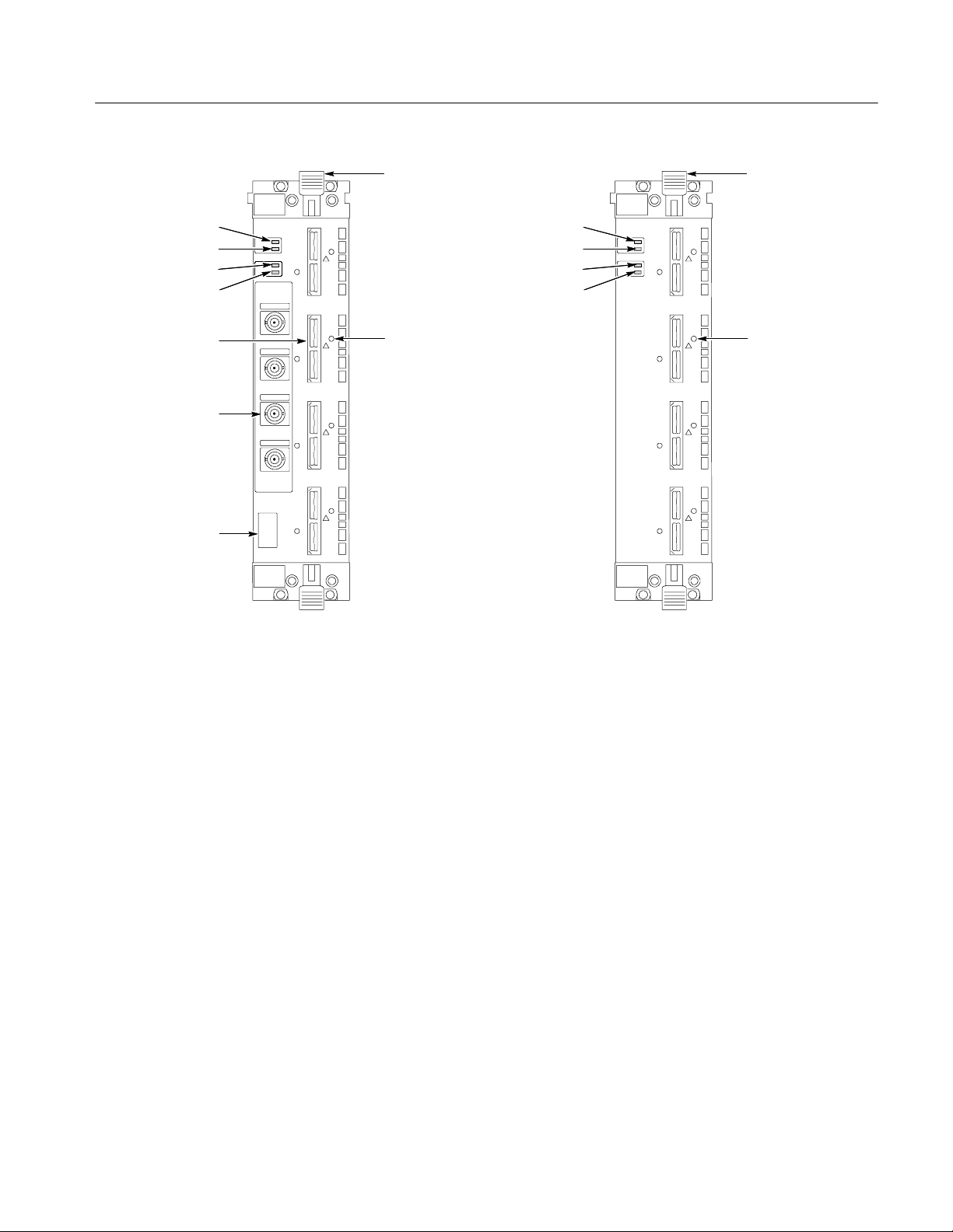
Front Panel
Figure 2--3 shows the connectors and indicators on the front panel of a 136-channel logic analyzer module. Modules with fewer channels look and operate the
same, but without the additional probe connectors.
Injector/Ejector Handles. The injector/ejector tabs are used to seat and unseat the
modules in the mainframe.
READY Indicator. The READY indicator lights continuously after the logic
analyzer module successfully completes the power-on process. If the indicator
fails to light within five seconds of power-on, an internal module failure may be
present.
ACCESSED Indicator. The ACCESSED indicator lights anytime the controller
accesses the logic analyzer module.
ARM’D Indicator. The ARM’D indicator lights when the logic analyzer module is
armed during an acquisition.
TRIG’D Indicator. The TRIG’D indicator lights when the logic analyzer module
triggers and stays on until the module finishes acquiring data.
2- 4
TLA7AXX/TLA7NAX Logic Analyzer Module Service Manual
Page 31
Operating Information
READY Indicator
ACCESSED Indicator
ARM’D Indicator
TRIG’D Indicator
Probe connectors
Analog signal
outputs
Configuration label
Injector/ejector
handle
E2
Probe retainer
mounting holes
READY Indicator
ACCESSED Indicator
ARM’D Indicator
TRIG’D Indicator
E2
Injector/ejector
handle
Probe retainer
mounting holes
TLA7AXX TLA7NAX
Figure 2- 3: Front panel of the TLA7Axx and TLA7NAx logic analyzer module
Probe Connectors. The probe connectors are color-coded to match the labels on
the probes. Each probe connector accepts a 34-channel active probe consisting of
32 data channels and two clock/qualifier channels.
Probe Retainer Mounting Holes. The threaded probe retainer mounting holes
provide a means of securely holding the probes in place. You must tighten the
retaining screws to ensure a good ground connection for the probes to the
module.
Analog Outputs. Each TLA7Axx module has four analog output BNC connectors
regardless of the number of acquisition channels. The analog output connectors
allow you to tap into the analog signal of any channel and connect the signals to
an external instrument, such as an oscilloscope. This feature allows you to view
the analog component of a selected channels without requiring a separate
oscilloscope probe connection.
TLA7AXX/TLA7NAX Logic Analyzer Module Service Manual
2- 5
Page 32
Operating Information
Configuration Label. Each TLA7Axx module has a configuration label that
indicates the speed and memory depth of the logic analyzer module.
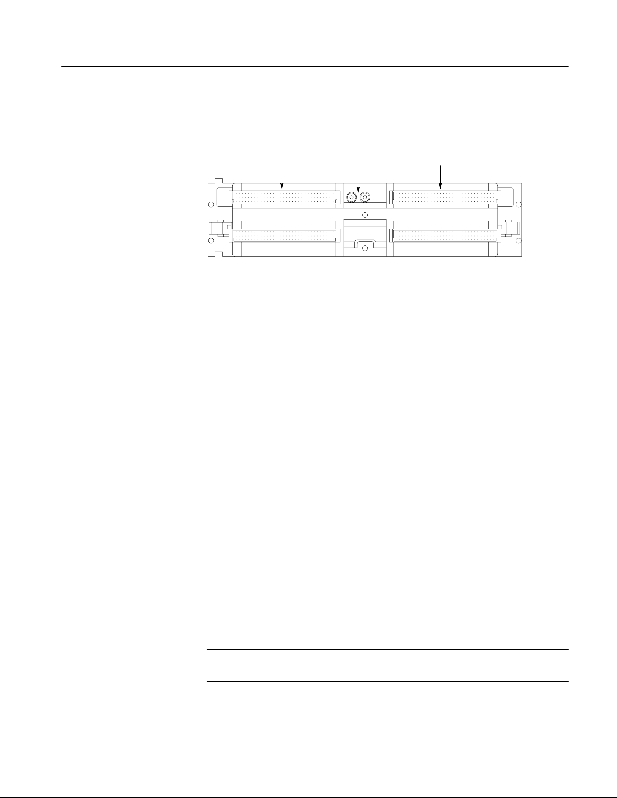
Merge Cable Connectors
Merge connectors on both sides of the module allow you to merge up to five
individual modules to create a single module with up to 680 channels with full
clock and trigger functionality. The 34-channel and 68-channel modules do not
have merge connectors.
The merge connector on the left side of the module can be physically extended to
connect with the connector of an adjacent module. The connector is shipped in
the recessed position and must be extended when merging modules (see
Figure 2--4).
The merge connector on the right side of the module provides play between
modules allow easy installation of the module set in a mainframe.
2- 6
Merge connector
Figure 2- 4: Merge connector on a TLA7Axx (shown in the extended position)
TLA7AXX/TLA7NAX Logic Analyzer Module Service Manual
Page 33
Operating Information
Rear Panel
Figure 2--5 shows the connectors and controls on the rear panel of the logic
analyzer module.
P1 Connector P2 Connector
Logical address
switches
Figure 2- 5: Rear panel controls and connectors
P1 and P2 Connectors. The acquisition board and the local processor unit (LPU)
provide the electrical connections from the module to the mainframe. These
electrical connections include power distribution, processor communications,
and intermodule communications.
Logical Address Switches. The logical address switches determine the logical
address of the module. These switches should normally be set to address FF. For
more information on these switches and their settings, refer to Logical Address
on page 2--1.
Online Help
Diagnostics
Most user information for operating the logic analyzer module is available
through the online help within the logic analyzer application. You can select the
online help from the Help menu, by clicking the Help button in a dialog box, or
by using the what’s this help (click the question mark icon, drag the cursor to the
item of interest on the screen, and then release the mouse button).
The logic analyzer module performs power-on diagnostics each time you power
on the mainframe. The Calibration and Diagnostics property sheet appears at
power-on if one or more of the diagnostics fail.
For more detailed tests, you can execute the extended diagnostics or the self
calibration. For more information on the diagnostics, refer to Calibration and
Diagnostic Procedures beginning on page 6--31.
NOTE. For best results, only run the diagnostics with the probes disconnected
from the module.
TLA7AXX/TLA7NAX Logic Analyzer Module Service Manual
2- 7
Page 34

Operating Information
Self Calibration
Self calibration is an internal routine that optimizes performance. No external
equipment or user actions are required to complete the procedure. The logic
analyzer saves the data generated by the self calibration in non-volatile memory.
NOTE. Performing the self calibration does not guarantee that all logic analyzer
module parameters operate within limits. Operation within limits is achieved by
performing the Adjustment Procedures. Proper operation may be confirmed by
having a qualified Tektronix Service Center technician perform the performance
verification procedures. See Service Options on page 7--3 for more information.
You can run the self calibration at any time during normal operation. To maintain
measurement accuracy, perform the self calibration if more than one year has
elapsed since the last self calibration.
You can check the status of the self calibration in the Calibration and Diagnostics
property sheet.
If the logic analyzer module loses power during the self calibration, rerun the
self calibration following the next power-on. The self calibration data generated
before power was interrupted must be replaced with a complete set of new data.
For best results, always perform the self calibration after at least a 30 minute
warm-up.
Menu Overview
The logic analyzer module may require several minutes to run the self calibration
depending on the number of channels. Select Calibration and Diagnostics
property sheet from the System menu. Select the Self Calibration tab page and
select the logic analyzer module. Click the Run button to start the self calibration. Upon completing the self calibration the logic analyzer module menu
selection changes from Running to Calibrated.
The logic analyzer is controlled by interactive windows through the TLA
application. The TLA application consists of the following windows:
H System Window. This window provides an overview of the entire logic
analyzer. Use this window to navigate through the logic analyzer.
The center of the System window displays icons that represent hardware
modules installed in the logic analyzer. The icons are linked to the other
windows in the logic analyzer.
H Setup Window. A setup window exists for each module in the logic analyzer.
It contains all of the setup information for the logic analyzer module such as
clocking, memory depth, threshold information, and channel information.
Menus and dialogs contain information to set up the window as needed.
2- 8
TLA7AXX/TLA7NAX Logic Analyzer Module Service Manual
Page 35

Operating Information
For the DSO, the Setup window contains setup information for each DSO
channel such as the input voltage ranges, bandwidth, coupling, and
termination. It also contains horizontal setup information and a link to the
DSO Trigger window.
An External Oscilloscope setup window may be present if your logic
analyzer connects to an external oscilloscope through the iView cable. This
setup window provides setup, trigger, and connection information for
oscilloscope and logic analyzer.
H Trigger Window. The Trigger window provides access to the logic analyzer
module or DSO module trigger setups. For either module, you can specify
various trigger events and trigger actions to help you capture the data that
you are interested in.
H Listing Data Window. The Listing Data window displays acquired data as
tabular text. Each column of data represents one group of data or other
logical data information, such as time stamps. Each row of data represents a
different time that the data was acquired; newer samples of data display
below older samples.
H Waveform Data Window. The Waveform Data window displays acquired
data as graphical waveforms. All defined channel groups display as busforms
for the logic analyzer and as individual analog channels for the DSO module.
H On/Off Buttons. These buttons enable or disable the operation of the
modules. Click the appropriate button to enable or disable the modules.
Refer to the online help for more information on the individual menus, icons,
and fields within each window. You may also want to refer to the Tektronix Logic
Analyzer Family User Manual for additional information.
TLA7AXX/TLA7NAX Logic Analyzer Module Service Manual
2- 9
Page 36

Operating Information
Merged Modules
The logic analyzer allows you to merge individual 102-channel or 136-channel
module modules to provide a logic analyzer module with up to 680 channels.
The following procedures provide information for merging and unmerging logic
analyzer modules.
Merging Rules
The following logic analyzer module merging rules must be followed:
H Only modules with 102 or 136 channels can be merged.
H Logic analyzer modules must be in adjacent slots and physically connected.
H Logic analyzer modules cannot be merged across mainframes.
H Merging logic analyzer modules with unequal memory depths will result in
the merged modules assuming the depth of the shallowest module.
H Merging logic analyzer modules with unequal speeds will result in the
merged modules assuming the speed of the slowest module.
H When merging logic analyzer modules of unequal channel widths, use the
logic analyzer module with the highest number of channels as the master
module. If there is a second slave module, the first slave must have greater
than or equal the number of channels as the second slave module. Slave 3
cannot have more channels than the master, slave 1 or slave 2. S lave 4
cannot have more channels than the master, slave 1, slave 2, or slave 3. See
Figure 2--6 on page 2--11 to determine the location of the master module
with the merged module set.
H The logic analyzer modules must have the same firmware version.
2- 10
H The maximum merged combinations are two TLA7Lx and TLA7Mx logic
analyzer modules; three TLA7Nx, TLA7Px, or TLA7Qx logic analyzer
modules; and five TLA7Axx and TLA7NAx logic analyzer modules.
H TLA7Nx, TLA7Px, and TLA7Qx Logic analyzer modules cannot be merged
with TLA7Lx and TLA7Mx Logic analyzer modules (even if they are
connected together).
H TLA7Axx and TLA7NAx modules cannot be merged with TLA7Nx,
TLA7Px, TLA7Qx, TLA7Lx, or TLA7Mx modules.
H Any combination of TLA7Axx and TLA7NAx modules (up to five) can be
merged.
H To merge a logic analyzer module to an established merged set, the
established merged set must first be unmerged through software. Unmerged
modules are the only potential candidates to add to a merged configuration.
TLA7AXX/TLA7NAX Logic Analyzer Module Service Manual
Page 37

Operating Information
Merge Procedure
Complete the following steps to create a merged module from two or more
individual modules. You must complete these steps prior to installing the
modules in a mainframe.
CAUTION. To avoid damaging the mainframe or any modules, always power
down the mainframe before removing or installing modules.
1. Determine which modules will reside in the highest-numbered slots in a
single mainframe.
2. Place the merge connector of these modules in the extended position. The
module in the lowest-numbered slot must have the merge connector in the
recessed position.
Use Figure 2--6 as a guide for determining the location of the master module
with the merged module set. Even though Figure 2--6 shows a five module
set, you can still use the illustration to position the master module with
respect to the slave module. For example, if you have a two module set, the
master module is located in the lower-numbered slot, and the slave module is
in the higher-numbered slot.
S
L
A
V
E
4
Figure 2- 6: Location of modules in a merged system
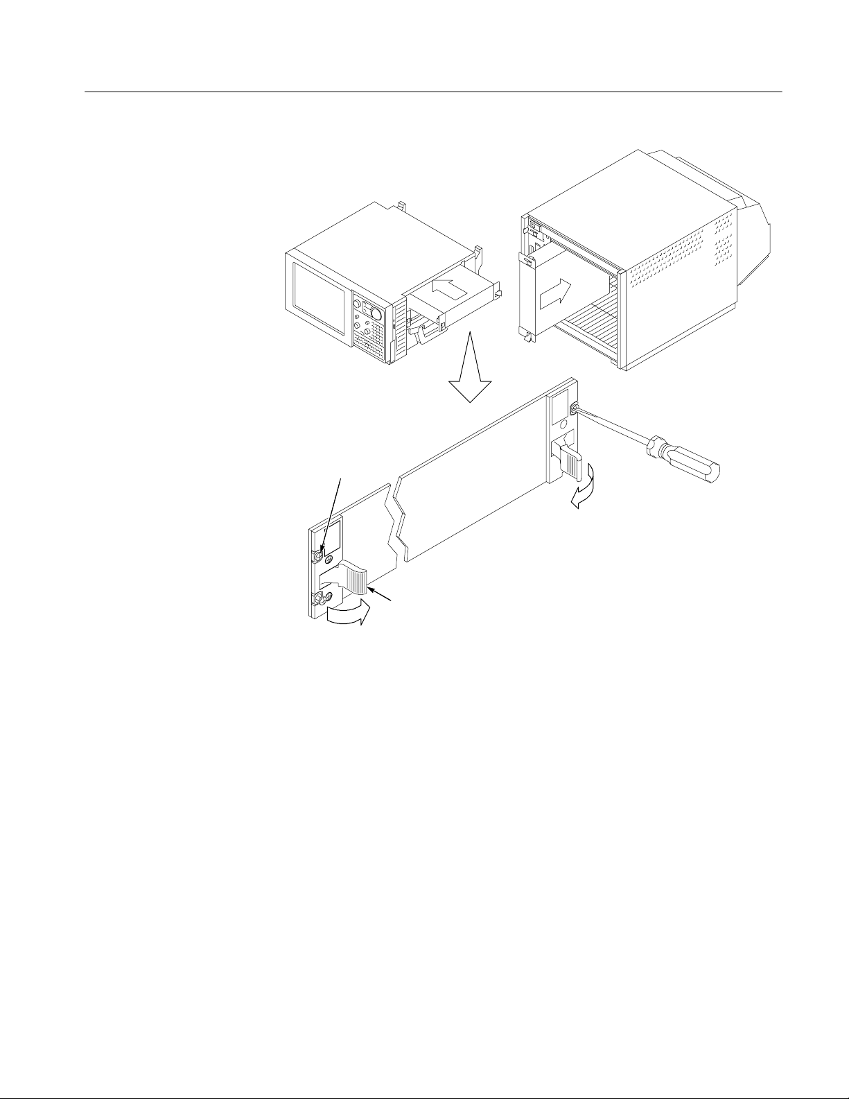
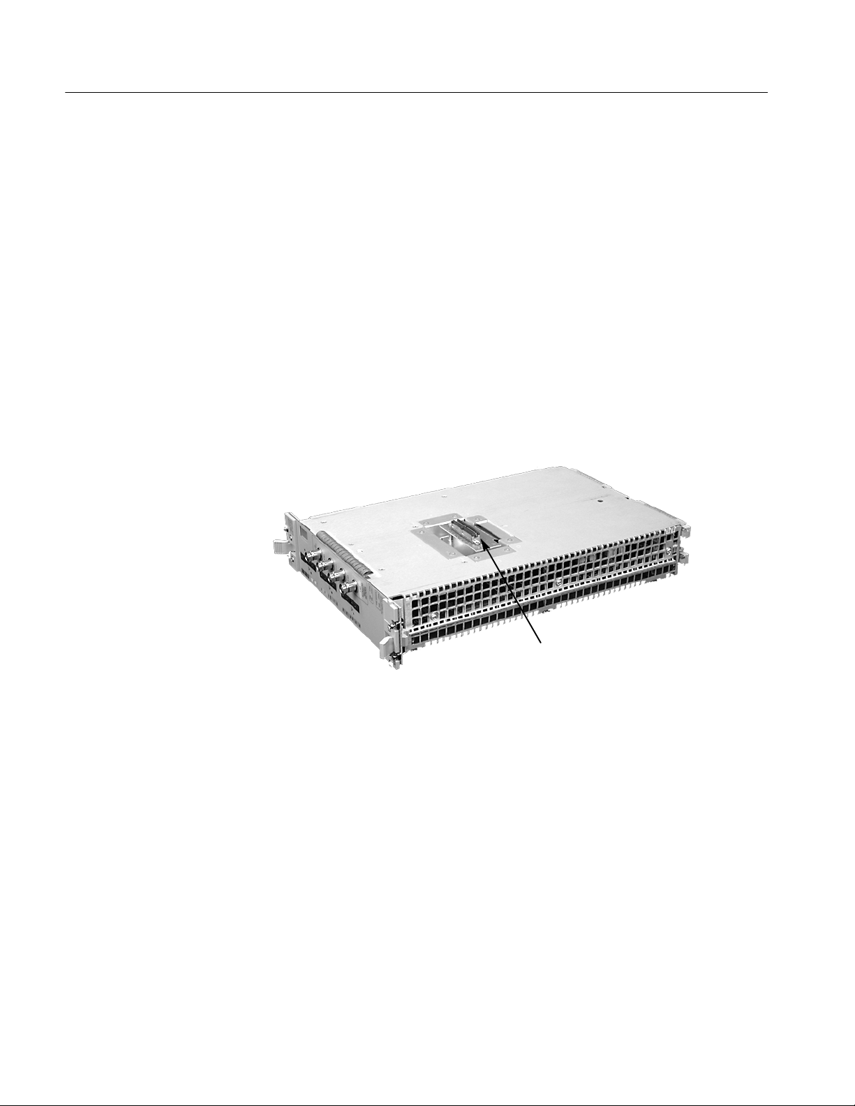
3. Place the module on the right side.
4. Using a Torx T-10 screw driver, remove the two screws holding the merge
connector to the module (see Figure 2--7).
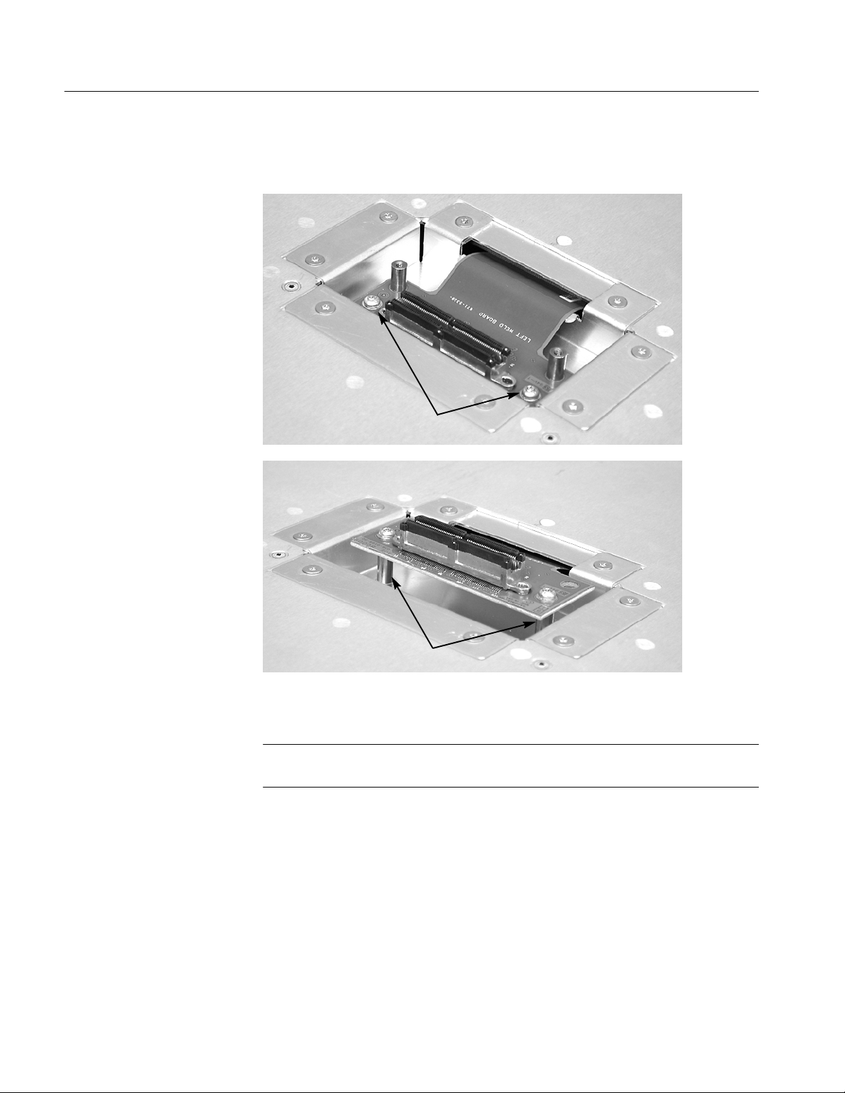
5. Gently lift the merge connector out of the slot and place it in the extended
position such that the screw holes line up over the two standoff posts.
6. Install the two screws into the standoff posts. Tighten the screws to 4-in. lbs.
S
L
A
V
E
2
M
A
S
T
E
R
S
L
A
V
E
1
S
L
A
V
E
3
TLA7AXX/TLA7NAX Logic Analyzer Module Service Manual
2- 11
Page 38
Operating Information
7. Repeat steps 3 through 6 for the remaining modules.
Remove two screws
2- 12
Standoff posts
Figure 2- 7: Removing the merge connector assembly from the module
NOTE. When installing the merged modules into a mainframe, you may need the
help of another individual.
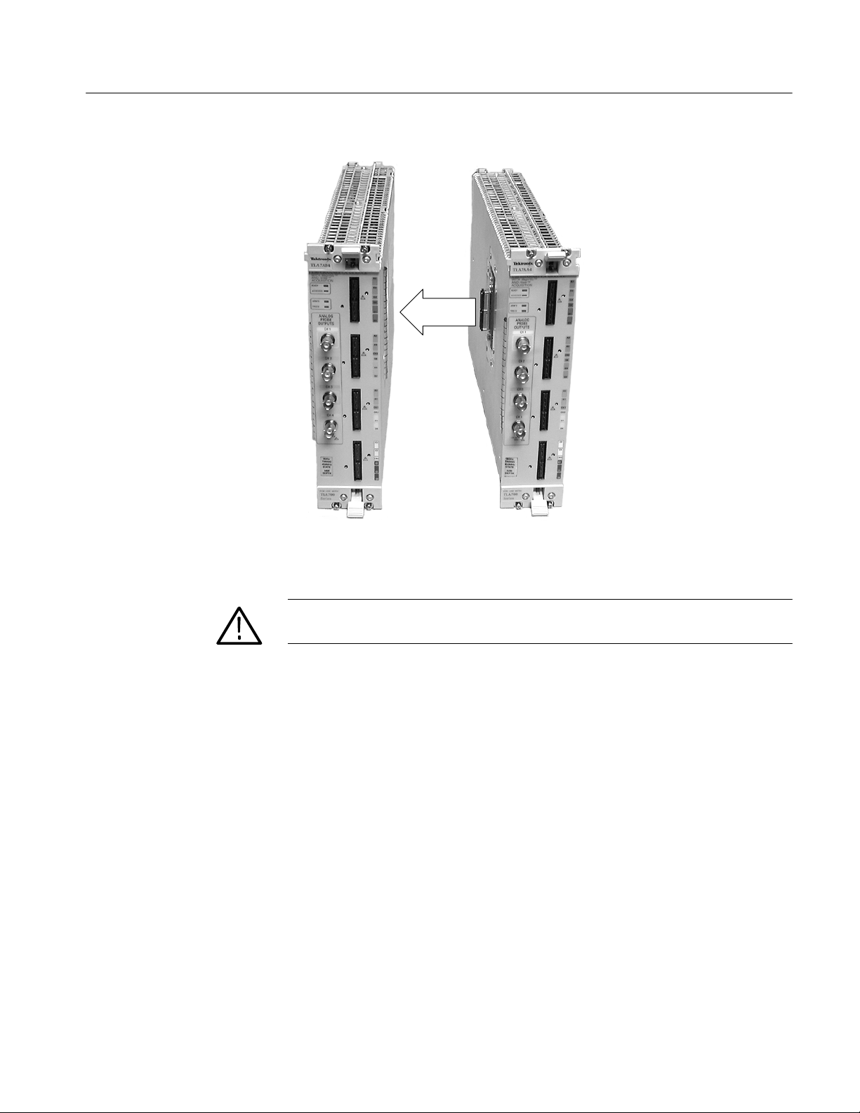
8. Place the first pair of modules to be merged side-by-side such that the merge
connector assemblies line up and connect between the two modules.
9. Push the two modules together until the connectors are seated in place.
10. Add any additional modules to the set.
TLA7AXX/TLA7NAX Logic Analyzer Module Service Manual
Page 39
Operating Information
Figure 2- 8: Connecting the logic analyzer modules together
CAUTION. Ensure that the mainframe is powered down before installing or
removing the modules.
11. Place the merged module set into the mainframe.
12. Align the tops and bottoms of the modules with the slots in the mainframe
(see Figure 2--9 on page 2--14). You may need the help of another individual
if your merged module set contains more than two modules.
TLA7AXX/TLA7NAX Logic Analyzer Module Service Manual
2- 13
Page 40

Operating Information
Align
Align
Slide module set
all the way in
2- 14
Latch in place
Figure 2- 9: Installing the merged module set in the mainframe
13. Slide the modules all the way into the mainframe until they rest against the
rear panel connectors.
TLA7AXX/TLA7NAX Logic Analyzer Module Service Manual
Page 41

Operating Information
14. Use the injector handles to firmly seat the modules in place one at a time and
then tighten the hold-down screws on each module. The merge cable
assembly should allow enough play between two side-by-side modules.
15. After installing all of the modules, power on the mainframe and complete the
merge process listed under the Merged Modules tab in the System Configuration dialog box.
Unmerge Procedure
Although you can unmerge modules from a merged set from within the TLA
application without physically separating modules, there will be times when you
have to physically unmerge the modules. The following procedures provide the
steps for unmerging the modules.
1. Power down the mainframe before removing the modules from the mainframe.
2. Use the ejector handles to disengage each module in the merged module set
from the mainframe.
3. With the assistance of another individual, slide all of the merged modules out
of the mainframe and place them on a static-free working surface.
4. Gently separate the modules on at a time from the merged module set.
5. Lay the modules on their right sides.
6. Remove the two Torx T-10 screws that hold the merge cable assembly to the
module.
7. Place the merge cable assembly into the recessed position.
8. Install the two Torx T-10 screws onto the assembly and tighten the screws to
4in-lbs.
9. Repeat steps 6 through 8 for the other modules.
You can now reinstall the modules in the mainframe as needed.
TLA7AXX/TLA7NAX Logic Analyzer Module Service Manual
2- 15
Page 42

Operating Information
2- 16
TLA7AXX/TLA7NAX Logic Analyzer Module Service Manual
Page 43

Theory of Operation
This chapter describes the general operation of the logic analyzer module. This
information is intended to help you isolate faults to the circuit board or probe
level. It supplements diagnostic and troubleshooting information presented in the
Troubleshooting section beginning on page 6--27.
The following Block Level Description describes circuit operation to the
functional block level. Block diagrams are located in the Diagrams chapter
beginning on page 9--1.
Block Level Description
The block level description provides an overview of each functional circuit
within the logic analyzer module. Except for the number of channels, the basic
operation is the same for each individual module and for merged modules.
The basic logic analyzer module consists of two main circuit boards: the Local
Processing Unit (LPU) board and the Acquisition board. Each circuit board has
two connectors on the rear of the boards that provide connections to the
mainframe.
Up to four active probes per module acquire data from the target system and send
it to the logic analyzer module for processing. The logic analyzer module can use
different types of probes (such as general purpose, high-density, or differential)
depending on the user’s application.
A single 102-channel or a 136-channel logic analyzer module can be merged
with up to five modules to create a two-, three-, four-, or five-module-wide logic
analyzer. The 34-channel and 68-channel modules do not support merging.
Local Processor Unit (LPU) Board
The LPU board controls instrument hardware, signal acquisition, power
conditioning, and communications functions. A 160-pin connector provides
interconnections with the acquisition board for power supplies, data and control
signals.
Processor System
The processor system contains a microprocessor that controls the entire
instrument. Commands and data sent to the instrument through the mainframe
pass through the communications interface, which resides on the bus. The bus
also routes data between the main processor system and the acquisition board.
TLA7AXX/TLA7NAX Logic Analyzer Module Service Manual
3- 1
Page 44

Theory of Operation
The processor system includes the instrument firmware. To facilitate upgrades,
the firmware resides in Flash ROM. The processor system also includes the
nonvolatile RAM (NVRAM) used for the calibration constants, module serial
numbers, and PowerFlex configuration information.
Communications Interface
Power Supplies
Acquisition Board
Clock Circuitry
Probe Interface
The Communications Interface transfers commands and data between the
mainframe and the mainframe controller. Signals pass between the logic analyzer
module and the mainframe through the rear connectors.
The onboard power supplies receive +5 V, --5.2 V, ±12 V, and ±24 V from the
mainframe through the rear connectors. Voltage converters produce the +2.5 V
supply for use on the acquisition board through the 160-pin connector between
the LPU and acquisition board.
The acquisition board accepts input signals from the probes and converts them to
digital information. A 160-pin connector provides interconnections with the LPU
board.
The system clock is derived from the 10 MHz clock from the backplane through
a phase-locked loop. The acquisition run circuitry is integrated with the clock
circuitry to support time correlation.
The probe interface consists of ASICs that receive data from the probes, compare
the data against a threshold, and transfer the digital information to CMOS ASICs
via differential outputs. Each ASIC in the probe interface receives 16 data
channels and one clock channel. In addition to providing digital signals to the
CMOS ASICs, the probe interface ASICs contain outputs for the Analog output
signals.
Analog Output Interface
Power Supplies
3- 2
The acquisition board for the TLA7Axx logic analyzer modules has four SMA
connectors that connect to the four BNC connectors on the front panel. The
software (via the user interface) determines which signals will be sent to the four
Analog output connectors. Regardless of the number of channels in the module,
there will always be four signals available to route to the Analog output
connectors.
Voltage converters produce the +3.3 V supply on the acquisition board and the
±3 V supplies for the active probes.
TLA7AXX/TLA7NAX Logic Analyzer Module Service Manual
Page 45

Theory of Operation
Trigger and Storage
Control Circuitry
Acquisition Memory
Clocking and triggering is controlled by a single ASIC. This ASIC determines
when acquisition data should be sampled based on the clock information and
qualifier information. The ASIC also contains 16 Event resources for the
purposes of word recognition, range recognition, and other trigger functions. In
merged configuration, the ASIC communicates information between modules to
ensure proper triggering.
The acquisition memory stores acquired data. The memory can be set up to store
all data samples, or it can be split to store data samples and either glitch
information or setup and hold violation information.
When the memory is split, only half the memory depth is available and can only
run at half the speed. Every stored data sample takes up two memory locations,
one to hold the actual data sample and the other to hold the corresponding glitch
information or the setup and hold information.
Glitch storage is only enabled with asynchronous clocking while setup and hold
storage is only enabled with synchronous clocking.
The trigger machine can trigger on either glitches or setup and hold violations
without storing information. This allows the user to trigger on a glitch or on a
setup and hold violation at maximum speed and maximum memory depth.
Backplane Interface
The backplane interface provides the interface with the mainframe and the
acquisition board. This interface contains intermodule signals that communicate
to other modules in the logic analyzer mainframe. The interface also provides the
10 MHz reference clock for the clocking circuitry.
TLA7AXX/TLA7NAX Logic Analyzer Module Service Manual
3- 3
Page 46

Theory of Operation
Probes
The logic analyzer module connects to the target system through 34-channel
probes (32 data channels and two clock/qualifier channels). Depending on the
number of channels in the logic analyzer module, you can connect up to four
logic analyzer probes to the module.
Currently six different types of active probes are supported for the logic analyzer
module:
H P6810 34-channel general purpose probe
H P6860 34-channel high-density single-ended probe
H P6864 17-channel high-density 4X single-ended probe
H P6880 34-channel high-density differential probe
H P6960 34-channel high-density single-ended probe with D-Max probing
technology
H P6980 34-channel high-density differential probe with D-Max probing
technology
The high-density probes connect directly to the circuit boards in the target
system. The probe connections are footprints designed on the circuit boards. The
footprints eliminate the need for additional electro-mechanical parts for probe
connectors.
The general purpose probes have lead sets that connect to several general-purpose connectors on the target system.
Detailed information on the probes is available in the P68xx Logic Analyzer
Probe Instruction Manual and the P69xx Logic Analyzer Probe Instruction
Manual.
3- 4
TLA7AXX/TLA7NAX Logic Analyzer Module Service Manual
Page 47

Merged Modules
Memory Erasure
Theory of Operation
A merged module consists of a Master module and one or more Slave modules
connected together by a merge cable connector. Each module has its own merge
cable connectors. The local bus sends the system clock of the Master module to
the Slave modules. The merged modules must be located in adjacent slots.
The merge connector passes 48 signals between adjacent modules excluding the
system clock. These signals consist of 16 trigger event signals, two storage
control signals, 26 clock sample/control signals, and four data-login control
signals.
To clear the volatile memory from the module you must turn the power off for at
least 20 seconds. NVRAM does not contain any acquisition data; it only contains
calibration constraints.
TLA7AXX/TLA7NAX Logic Analyzer Module Service Manual
3- 5
Page 48

Theory of Operation
3- 6
TLA7AXX/TLA7NAX Logic Analyzer Module Service Manual
Page 49

Performance Verification
This chapter contains procedures for functional verification. It is recommended
that you check the electrical performance and certify the logic analyzer accuracy
once a year or following repairs that affect certification. For TLA7Axx/
TLA7NAx modules, this service must be performed by a qualified Tektronix
Service Center technician. See Service Options on page 7--3 for more informa-
tion.
Functional Verification
Functional verification procedures verify the basic functionality of the instrument inputs, outputs, and basic instrument actions. These procedures include
power-on diagnostics, extended diagnostics, and manual check procedures. You
can use these procedures for incoming inspection purposes.
If any check within this section fails, refer to the Troubleshooting section in the
Maintenance chapter of this manual for assistance. Failed tests indicate the
instrument needs to be serviced.
The functional verification procedure consists of the following parts:
H Module self tests and power-on diagnostics
H Extended diagnostics
H Probe functional verification
This procedure provides a functional check only. If more detailed testing is
required, refer to Service Options on page 7--3 to have Tektronix Service perform
the Performance Verification Procedures.
Perform these tests whenever you need to gain confidence that the instrument is
operating properly.
TLA7AXX/TLA7NAX Logic Analyzer Module Service Manual
4- 1
Page 50

Performance Verification
Test Equipment
Setup
Module Self Tests and
Power-On Diagnostics
You will need the following equipment to complete the functional verification
procedure:
H TLA700 Series logic analyzer mainframe with one logic analyzer module
installed (more modules are required to check the merged functionality)
H At least one logic analyzer probe
It is assumed that the logic analyzer module is properly installed in the mainframe. Refer to Module Installation on page 2--2 for module installation
instructions.
Power on the logic analyzer mainframe and allow a 30-minute warm-up period
before continuing with any procedures in this section.
During power-on, the installed modules perform an internal self test to verify
basic functionality. No external test equipment is required. The self tests require
only a few seconds per module to complete. The front-panel ARM’Dand
TRIG’D indicators blink during the self test. After testing completes, the front
panel indicators have the following states:
H READY — Green (on)
H ACCESSED — off
H ARM’D — off
H TRIG’D — off
Next, the power-on diagnostics are run. If any self tests or power-on diagnostics
fail, the instrument displays the Calibration and Diagnostics property sheet.
NOTE. If any diagnostics fail, you may need to run the self calibration before
attempting to service the logic analyzer module. This may be especially true
after you install the logic analyzer module in the mainframe for the first time.
The Self Calibration procedure is listed under Self Calibration beginning on
page 5--1.
4- 2
TLA7AXX/TLA7NAX Logic Analyzer Module Service Manual
Page 51

Performance Verification
Logic Analyzer Module
Functional Verification
Procedure
The following procedure checks the basic functionality of the logic analyzer
module. You can perform this procedure with individual modules or with merged
modules. Functional verification consists of running the extended diagnostics.
NOTE. Running the extended diagnostics invalidates any acquired data. If you
want to save any of the acquired data, do so before running the extended
diagnostics.
Perform the following steps to complete the functional verification procedures:
1. Disconnect any probes connected to the logic analyzer module.
2. In the logic analyzer application, go to the System menu and select
Calibration and Diagnostics.
3. Click the Extended Diagnostics tab.
4. Select the top level test and click the Run button.
The diagnostics will perform each one of the tests listed in the menu under
the module selection. All tests that displayed an Unknown status will change
to a Pass or Fail status depending on the outcome of the tests.
5. Scroll through the test results and verify all tests pass.
Probe Functional
Verification
NOTE. If the extended diagnostics fail, run the self calibration procedures as
described under Self Calibration beginning on page 5--1 for the logic analyzer
module under test and then rerun the extended diagnostics.
To perform a functional test on your logic analyzer probes, use a
NEX--PROBETESTER2 from Nexus Technology. Follow the procedure listed
for a functional test in the NEX--PROBETESTER2 manual. For more information, see the Nexus Technology Web site at www.busboards.com.
To have Tektronix service perform the performance verification procedures,
which will verify that the logic analyzer and the attached probes meet or exceed
the advertised specifications, refer to Service Options on page 7--3.
TLA7AXX/TLA7NAX Logic Analyzer Module Service Manual
4- 3
Page 52

Performance Verification
4- 4
TLA7AXX/TLA7NAX Logic Analyzer Module Service Manual
Page 53

Adjustment Procedures
This chapter contains procedures for self calibration. Adjustments must be
performed when performance verification tests have failed. Adjustments must
also be made following replacement of any circuit board in the logic analyzer
module. For TLA7Axx/TLA7NAx modules, adjustments must be performed by
a qualified Tektronix Service Center technician. See Service Options on page 7-- 3
for more information.
Self Calibration
Self calibration is an internal routine that optimizes performance at the current
ambient temperature to maximize measurement accuracy. No external equipment
or user actions are needed to complete the procedure. The logic analyzer module
saves data generated by the self calibration in nonvolatile memory. Passing self
calibration provides a higher level of confidence of module functionality.
NOTE. Performing the self calibration does not guarantee that all parameters
operate within limits. Operation within limits is achieved by performing the
adjustment procedures. Verification of operation within limits is accomplished by
performing the performance verification procedures.
You can run the self calibration at any time during normal operation. To maintain
measurement accuracy, perform the self calibration if the following conditions
occur:
H After repair and replacement of any circuit board.
H It has been a year since the last self calibration was run.
TLA7AXX/TLA7NAX Logic Analyzer Module Service Manual
5- 1
Page 54

Adjustment Procedures
To perform the self calibration procedure, do the following:
1. Ensure that the instrument has had a 30-minute warm up before attempting
the self calibration, and that the logic analyzer application is running.
2. Disconnect any probes connected to the logic analyzer module.
3. Select Calibration and Diagnostics from the System menu.
4. Select the Self Calibration tab page.
5. Select the logic analyzer module.
6. Click the Run button to start the self calibration.
The self calibration takes several minutes to complete, depending on the
number of channels in the module. Upon successfully completing the self
calibration, the module status changes from Running to Calibrated, and the
Date and Time field is set to the present.
5- 2
TLA7AXX/TLA7NAX Logic Analyzer Module Service Manual
Page 55
Maintenance
This chapter contains the information needed for periodic and corrective
maintenance of the Logic Analyzer Modules. The following sections are
included.
H This Maintenance section provides general information on preventing
damage to internal circuit boards when doing maintenance, procedures for
inspecting the logic analyzer module, and cleaning external and internal
circuit boards.
H The Removal and Installation Procedures (page 6--11) provide procedures
for removing and installing circuit boards and other common replaceable
parts.
H Troubleshooting (page 6--27) provides information for isolating faulty circuit
boards, probes, and other faults.
H Repackaging Instructions (page 6--41) provides packaging information for
shipment or storage.
Related Maintenance Procedures
The TLA7UP Mainframe Field Upgrade Instruction Manual contains some
maintenance procedures not included in this manual. Refer to the TLA7UP
Mainframe Field Upgrade Instruction Manual for information on upgrading the
mainframe software or module firmware.
Preventing Electrostatic Discharge
When performing any service that requires internal access to the logic analyzer
module, adhere to the following precautions to avoid damaging internal modules
and their components due to electrostatic discharge (ESD).
CAUTION. Static discharge can damage any semiconductor component.
H Minimize handling of static-sensitive modules.
H Transport and store static-sensitive modules in their static protected
containers. Label any package that contains static-sensitive modules.
H Wear a grounded antistatic wrist strap while handling these modules. Service
static-sensitive modules only at a static-free work station.
TLA7AXX/TLA7NAX Logic Analyzer Module Service Manual
6- 1
Page 56

Maintenance
H Nothing capable of generating or holding a static charge should be allowed
H Handle circuit boards by the edges when possible.
H Do not slide the modules over any surface.
H Avoid handling the modules in areas that have a floor or work surface
Inspection and Cleaning
Inspection and cleaning are done as preventive maintenance. Preventive
maintenance, when done regularly, may prevent malfunctions and enhance
reliability.
Preventive maintenance consists of visually inspecting and cleaning the
instrument, and using general care when operating it. How often to perform
maintenance depends on the severity of the environment in which the instrument
is used. A proper time to perform preventive maintenance is just before having
performance verification procedures performed or as an incoming inspection.
on the work surface.
capable of generating a static charge.
General Care
Inspection and Cleaning
Procedures
The side cover keeps dust out of the instrument and should be in place during
normal operation.
Inspect and clean the instrument as often as operating conditions require.
Collection of dirt on internal components can cause them to overheat and
breakdown. Dirt acts as an insulating blanket, preventing efficient heat dissipation. Dirt also provides an electrical conduction path that can cause failures,
especially under high-humidity conditions.
CAUTION. Avoid using chemical cleaning agents that might damage the plastics
and external labels used in the instrument.
Use a cloth dampened with water to clean external surfaces. To prevent damage
to electrical components from moisture during external cleaning, use only
enough liquid to dampen the cloth or applicator.
Use a 75% isopropyl alcohol solution to clean internal surfaces and rinse with
deionized water. Before using any other type of cleaner, consult your Tektronix
Service Center or representative.
6- 2
TLA7AXX/TLA7NAX Logic Analyzer Module Service Manual
Page 57
Maintenance
Exterior Inspection
Inspect the outside of the instrument for damage, wear, and missing parts. Use
Table 6--1 as a guide. Instruments that appear to have been dropped or otherwise
abused should be checked thoroughly to verify correct operation and performance.
Immediately repair defects that can cause personal injury or lead to further
damage to the logic analyzer module or mainframe where it is used.
Table 6- 1: External inspection check list
Item Inspect for Repair action
Front panel and side
cover
Front panel connectors Broken shells, cracked insulation,
Rear connectors Cracked or broken shells, dam-
Accessories Missing items or parts of items,
Cracks, scratches, deformations,
missing or damaged retainer
screws, ejector handles, or EMI
shields.
and deformed contacts.
Dirt in connectors.
aged or missing contacts.
Dirt in connectors.
bent pins, broken or frayed
cables, and damaged connectors.
Replace defective or missing
mechanical parts.
Replace defective parts or clean
parts based on the cleaning
procedures.
Replace defective parts or clean
parts based on the cleaning
procedures.
Replace damaged or missing
items, frayed cables, and defective modules.
Exterior Cleaning
Procedure
To clean the exterior, perform the following steps:
1. Remove loose dust on the outside of the logic analyzer module with a lint
free cloth.
2. Remove remaining dirt with a lint-free cloth or applicator and water, using
only enough liquid to dampen the cloth or applicator. Do not use abrasive cleaners.
TLA7AXX/TLA7NAX Logic Analyzer Module Service Manual
6- 3
Page 58
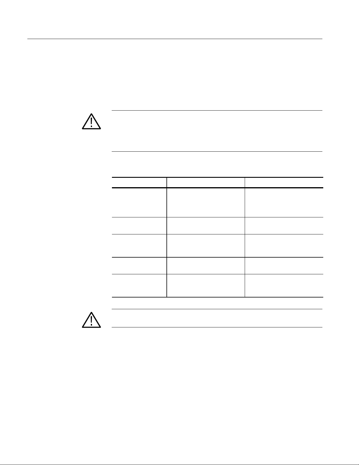
Maintenance
Interior Inspection
Inspect the internal portions of the logic analyzer module for damage and wear
using Table 6--2 as a guide. When found, defects should be repaired immediately.
If you must replace an internal component, refer to the Removal and Installation
Procedures, later in this chapter, for detailed removal and replacement instructions.
CAUTION. Do not attempt to repair any circuit boards with a soldering iron.
Most of the internal components are surface mounted devices. Using a soldering
iron can damage the surface-mounted components and internal circuit boards.
Refer the replacement of surface-mounted components to qualified service
personnel with the appropriate tools.
Table 6- 2: Internal inspection checklist
Item Inspect for Repair action
Circuit boards Loose, broken, or corroded
connections. Burned circuit
boards. Burned, broken, or
cracked circuit-run plating.
Resistors Burned, cracked, broken, blis-
tered condition.
Remove failed circuit board and
replace with a new one.
Remove failed circuit board and
replace with a new one.
Interior Cleaning
Procedure
Capacitors Damaged or leaking cases.
Corroded solder on leads or
terminals.
Semiconductors Damaged parts or distorted pins. Replace circuit board if parts are
Wiring and cables Loose plugs or connectors.
Burned, broken, or frayed wiring.
Remove failed circuit board and
replace with a new one.
damaged.
Firmly seat connectors. Repair or
replace circuit boards with defective wires or cables.
CAUTION. To prevent damage from electrical arcing, ensure that circuit boards
and components are dry before applying power to the logic analyzer module.
To clean the interior, perform the following steps:
1. Blow off dust with dry, low-pressure, deionized air (approximately 9 psi).
2. Remove any remaining dust with a lint free cloth dampened in isopropyl
alcohol (75% solution) and rinse with warm deionized water. (A cottontipped applicator is useful for cleaning in narrow spaces and on circuit
boards.)
6- 4
TLA7AXX/TLA7NAX Logic Analyzer Module Service Manual
Page 59
Maintenance
NOTE. If, after performing steps 1 and 2, a module is clean upon inspection, skip
the remaining steps. If steps 1 and 2 do not remove all the dust or dirt, the
module may be spray washed using a solution of 75% isopropyl alcohol (see
steps 3 through 7).
3. Gain access to the parts to be cleaned by removing easily accessible shields
and panels (see Removal and Installation Procedures on page 6--11).
4. Spray wash dirty parts with the isopropyl alcohol and wait 60 seconds for the
majority of the alcohol to evaporate.
5. Use warm (48.9 _Cto60_C / 120 _F to 140 _F) deionized water to
thoroughly rinse the parts.
6. Dry all parts with low-pressure, deionized air.
7. Dry all components and assemblies in an oven or drying compartment using
low-temperature (51.7 _C to 65.6 _C / 125 _F to 150 _F) circulating air.
Cleaning the Probes
To clean the exterior surfaces of the probes, remove dirt and dust with a soft
brush. For more extensive cleaning, use only a damp cloth. Never use abrasive
cleaners or organic solvents
CAUTION. Static discharge can damage any semiconductor component in the
probe head. Always wear a grounded antistatic wrist strap whenever handling
the probe head. Also verify that anything to which the probe head is connected
does not carry a static charge.
NOTE. Never clean the elastomers. Always replace them instead. Refer to the
P68XX Series Logic Analyzer Probe Instruction Manual for information on
replacing the probe elastomers and other probe accessories.
TLA7AXX/TLA7NAX Logic Analyzer Module Service Manual
6- 5
Page 60
Maintenance
Cleaning the P6864, P6880, P6960, and P6980 Compression Footprints
CAUTION. To avoid electrical damage, always turn off the power of your target
system before cleaning the compression footprint.
Prior to connecting the probe to the target system, the compression footprints on
the target system must be properly cleaned. Clean the compression footprints
according to the following steps:
1. Use a lint-free cloth moistened with isopropyl alcohol and gently wipe the
footprint surface.
2. Remove any remaining lint using a nitrogen air gun.
NOTE. Use alcohol sparingly and be sure that you have removed any remaining
lint or residue with the nitrogen air gun.
Cleaning the P6864, and P6880 Probe Heads
Before connecting the P6864 or P6880 probes to the target system, ensure that
the probe heads are free from dust, dirt, and contaminants. If necessary, clean the
probe heads according to the following steps.
CAUTION. Static discharge can damage semiconductor components in the probe
head. Always wear a grounded antistatic wrist strap whenever handling the
probe head. Also verify that anything to which the probe head is connected does
not carry a static charge.
NOTE. Never clean the elastomers. Always replace them instead. Refer to the
Operating Basics chapter of the P68XX Series Logic Analyzer Probe Instruction
Manual for information on replacing elastomers.
6- 6
TLA7AXX/TLA7NAX Logic Analyzer Module Service Manual
Page 61
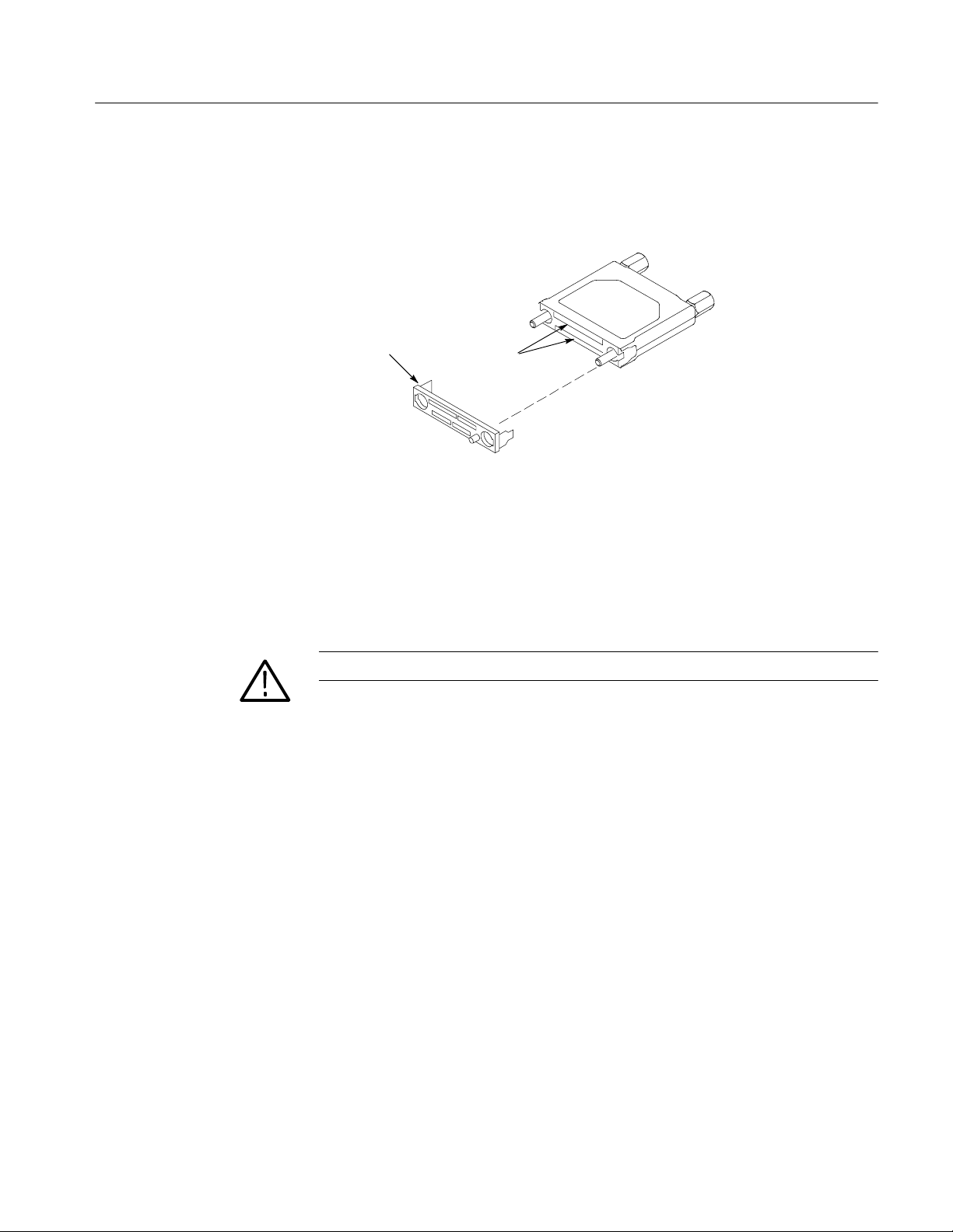
1. Remove elastomer holder (see Figure 6--1).
2. Moisten a cotton swab with isopropyl alcohol.
Maintenance
Elastomer holder
Print pads
Figure 6- 1: Cleaning the probe heads
3. Gently wipe the edge print pads of the hybrid.
4. Remove any remaining lint using a nitrogen air gun.
5. Put the elastomer holder back in place.
CAUTION. Do not touch the elastomers to avoid damaging the probe contacts.
TLA7AXX/TLA7NAX Logic Analyzer Module Service Manual
6- 7
Page 62
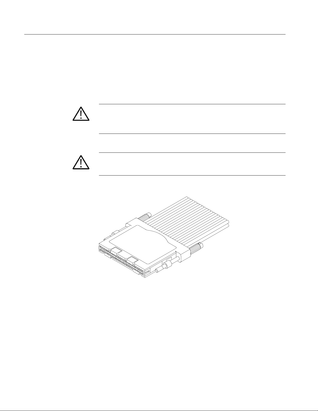
Maintenance
Cleaning the P69xx Probe Heads
To maintain a reliable electrical contact, keep the probes free from dirt, dust, and
contaminants. Remove dirt and dust with a soft brush. Avoid brushing or rubbing
the c-spring contacts. For more extensive cleaning, use only a damp cloth. Never
use abrasive cleaners or organic solvents.
CAUTION. Static discharge can damage semiconductor components in the probe
head. Always wear a grounded antistatic wrist strap whenever handling the
probe head. Also verify that anything to which the probe head is connected does
not carry a static charge.
CAUTION. To prevent damage during the probe connection process, do not touch
the exposed edge of the interface clip. Do not drag the contacts against a hard
edge or corner.
6- 8
Figure 6- 2: Cleaning the P69xx probe heads
TLA7AXX/TLA7NAX Logic Analyzer Module Service Manual
Page 63
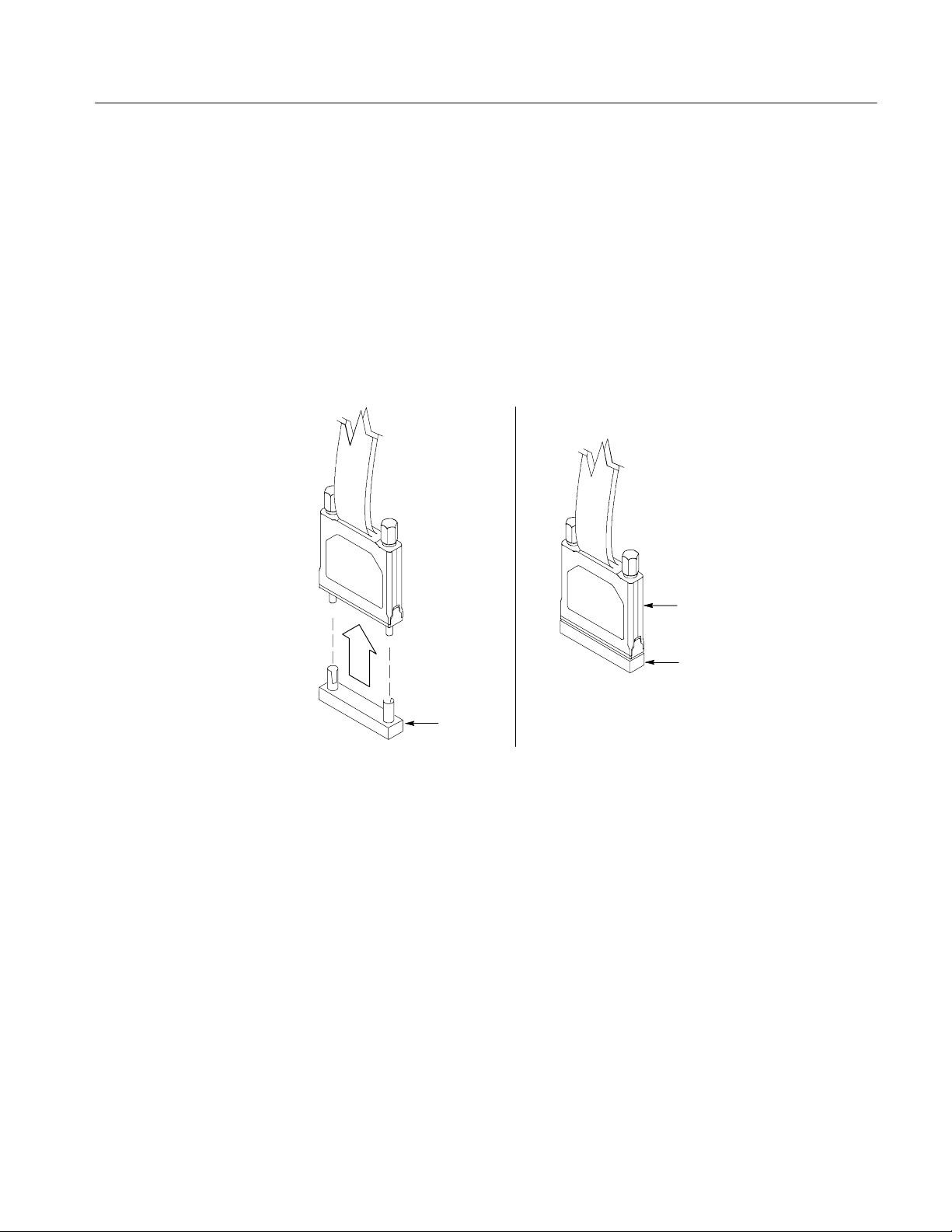
Storing the P68xx Probe Heads
To protect the elastomer, it is important to properly store the probe heads when
the probes are not in use. See Figure 6--3.
1. Locate the keying pin on the probe end and align it to the keying pin hole on
the nutbar.
2. While holding the probe end at a perpendicular angle to the nutbar,
finger--tighten both probe head screws until snug (no more than 1 in-lbs of
torque).
Maintenance
Nutbar
Figure 6- 3: Storing the probe head
Safely store the
probe head
Nutbar
TLA7AXX/TLA7NAX Logic Analyzer Module Service Manual
6- 9
Page 64

Maintenance
Storing the P69xx Probe Heads
To protect the probe head, when the probes are not in use place the probe head
cover on the probe. See Figure 6--4.
1. Gently slide the probe cover over the probe end.
Protective
cover
Figure 6- 4: Storing the P69xx probe heads
6- 10
TLA7AXX/TLA7NAX Logic Analyzer Module Service Manual
Page 65
Removal and Installation Procedures
This section describes how to remove and install the major mechanical and
electrical modules. The procedures in this section assume that you already have
removed the module from the mainframe.
WARNING. Before doing any procedures in this manual, read the General Safety
Summary and Service Safety Summary found at the beginning of this manual.
T o prevent possible injury to service personnel or damage to electrical components, read Preventing Electrostatic Discharge on page 6--1.
Tools Required
Table 6--3 lists the tools needed to replace the internal components of the logic
analyzer module.
Table 6- 3: Tools required for circuit board replacement
Torque Requirements
Name Description
Screwdriver with a T-9 and a T-10 Torx tip Standard tool
1/4-inch nut driver Standard tool
9/16-inch nut driver Standard tool
Needle-nose pliers Standard tool
Tighten all T-9 and T-10 screws to 4 in. lbs. Tighten standoff posts to 8 in. lbs.
TLA7AXX/TLA7NAX Logic Analyzer Module Service Manual
6- 11
Page 66
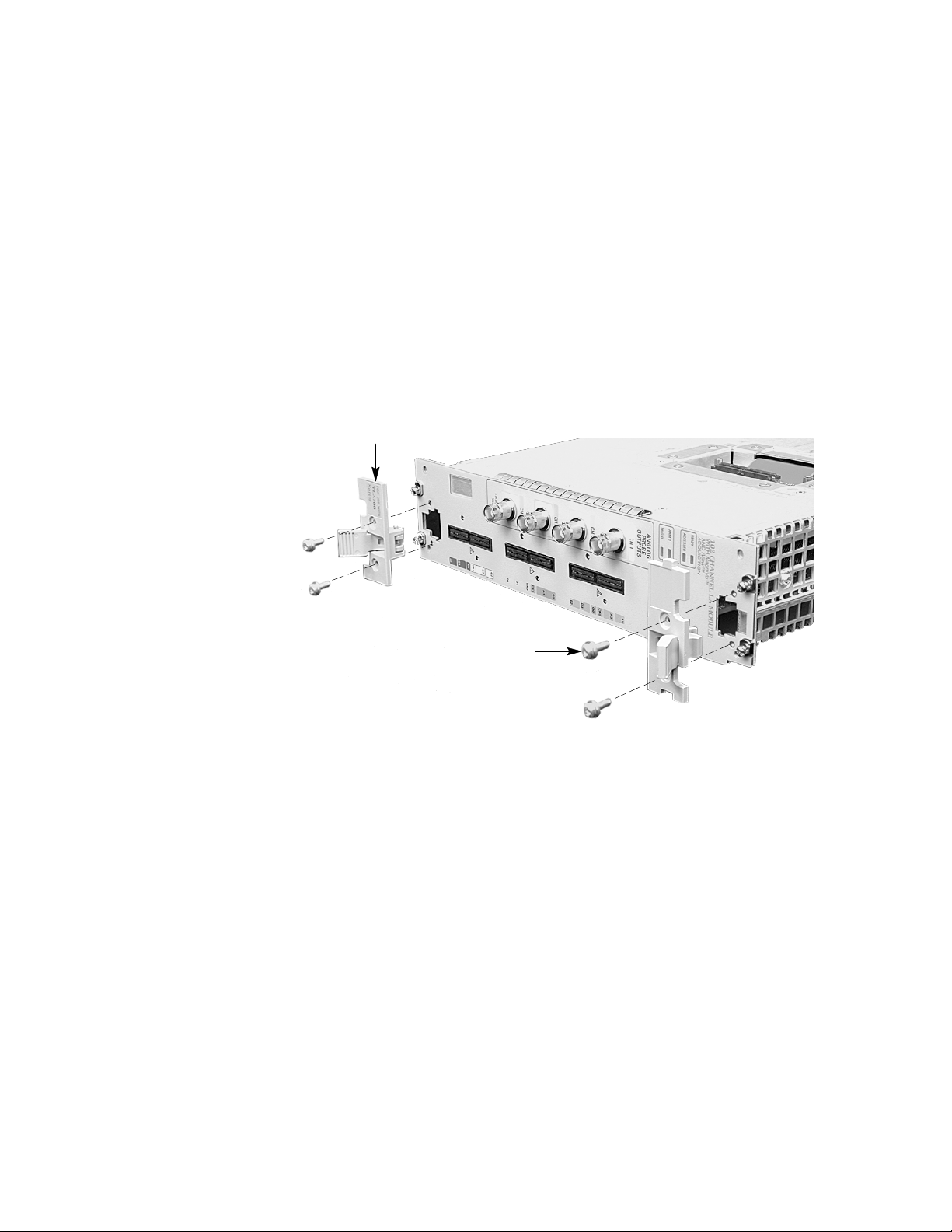
Removal and Installation Procedures
Injector/Ejector Handles
You will need a screwdriver with a T-10 tip to complete the following procedures.
Removal
Use the following procedure to remove the injector/ejector handles:
1. Place the module on the right side (see Figure 6--5).
2. Remove the two screws that secure the injector/ejector handle to the chassis.
3. Remove the injector/ejector handle from the module.
Ejector handles (2)
Remove screws (4)
6- 12
Figure 6- 5: Injector/ejector handle replacement
TLA7AXX/TLA7NAX Logic Analyzer Module Service Manual
Page 67

Removal and Installation Procedures
Covers
Installation
Use the following procedure and Figure 6--5 to install the injector/ejector
handles:
NOTE. The top and bottom injector/ejector handles are not interchangeable. The
top injector/ejector handle assembly has a notch on right side and a tab on the
left side; the bottom injector/ejector handle assembly does not have a notch or a
tab.
1. Install the injector/ejector handle through the front panel cutout onto the
mounting post.
2. Install the screws to secure the injector/ejector handle to the chassis.
3. Apply the proper replacement label (see the Replaceable Mechanical Parts
List for label part numbers if necessary).
You will need a screwdriver with a T-9 and a T-10 tip to complete the following
procedures.
Removal
Use the following procedure and Figures 6--6 and 6--7 to remove the covers:
1. Place the module on the right side.
2. Remove the two screws on the rear of the chassis and the two rear screws,
located on either side of the rear panel, that secure the rear panel to the
chassis.
3. Remove the rear panel and set it aside.
4. Remove the two top screws and the two bottom screws that secure the cover
to the chassis.
5. If you have a 102-channel module or a 136-channel module with a merge
cable, complete to following steps (refer to Figure 6--6 as necessary):
a. Remove the eight T-9 countersunk screws holding the bracket to the
cover.
b. Lift the assembly out of the cover and then reach into the hole and
disconnect the merge cable from the circuit board.
6. Slide the cover back to disengage the tab and lift the cover from the chassis.
TLA7AXX/TLA7NAX Logic Analyzer Module Service Manual
6- 13
Page 68

Removal and Installation Procedures
Screws (8)
Cable bracket
Disconnect merge
cable from the board
Figure 6- 6: Removing the merge cable bracket from the cover
6- 14
TLA7AXX/TLA7NAX Logic Analyzer Module Service Manual
Page 69

Removal and Installation Procedures
Installation
Screws (3)
Screws (2)
Rear panel
Cover
Chassis
Screws (3)
Figure 6- 7: Cover removal
Use the following procedure and Figure 6--6 through Figure 6--9 to install the
covers:
NOTE. Install the cover tightly against the chassis. This will ensure that the
module fits into adjacent slots in the mainframe.
1. Place the module on its right side.
CAUTION. To prevent damage to the module during the installation process,
reinstall the cover exactly as described in steps 2 through 8.
If the cover is not properly seated, the module can be damaged when you install
it in a mainframe.
2. Insert the cover at an angle (step 1 in Figure 6--8) such that the front edge of
the cover engages with the EMI gaskets on the back of the front panel. Then
push the rear of the cover in place (step 2 Figure 6--8).
TLA7AXX/TLA7NAX Logic Analyzer Module Service Manual
6- 15
Page 70

Removal and Installation Procedures
1
2
Figure 6- 8: Installing the cover onto the chassis
3. Make sure that the cover is fully seated (no gaps) against the front and rear
chassis flanges (see Figure 6--9).
4. While holding the cover in place, install the four T -10 T orx-drive screws
nearest the front of the module (two on each side of the cover), to secure the
cover to the chassis.
5. Slide the rear panel on the chassis and install the two rear panel T-10
Torx-drive screws.
6- 16
6. Gently squeeze the chassis flange and rear panels flange together while
tightening the screws on the sides. This ensures that the rear panel does not
rotate, otherwise the module may not seat properly when installed in the
mainframe.
7. Install the two remaining T-10 Torx-drive screws nearest the rear of the
module (one on each side of the cover).
8. Place the cover onto the chassis.
9. If your instrument has a merge cable, complete the following steps to install
the merge cable assembly:
a. Feed the merge cable through the cover.
b. Carefully connect the merge cable to the circuit board (refer to
Figure 6--6 on page 6--14 as necessary).
c. Insert the bracket assembly into the hole in the cover.
d. Install the eight T-9 countersunk screws on the bracket.
TLA7AXX/TLA7NAX Logic Analyzer Module Service Manual
Page 71
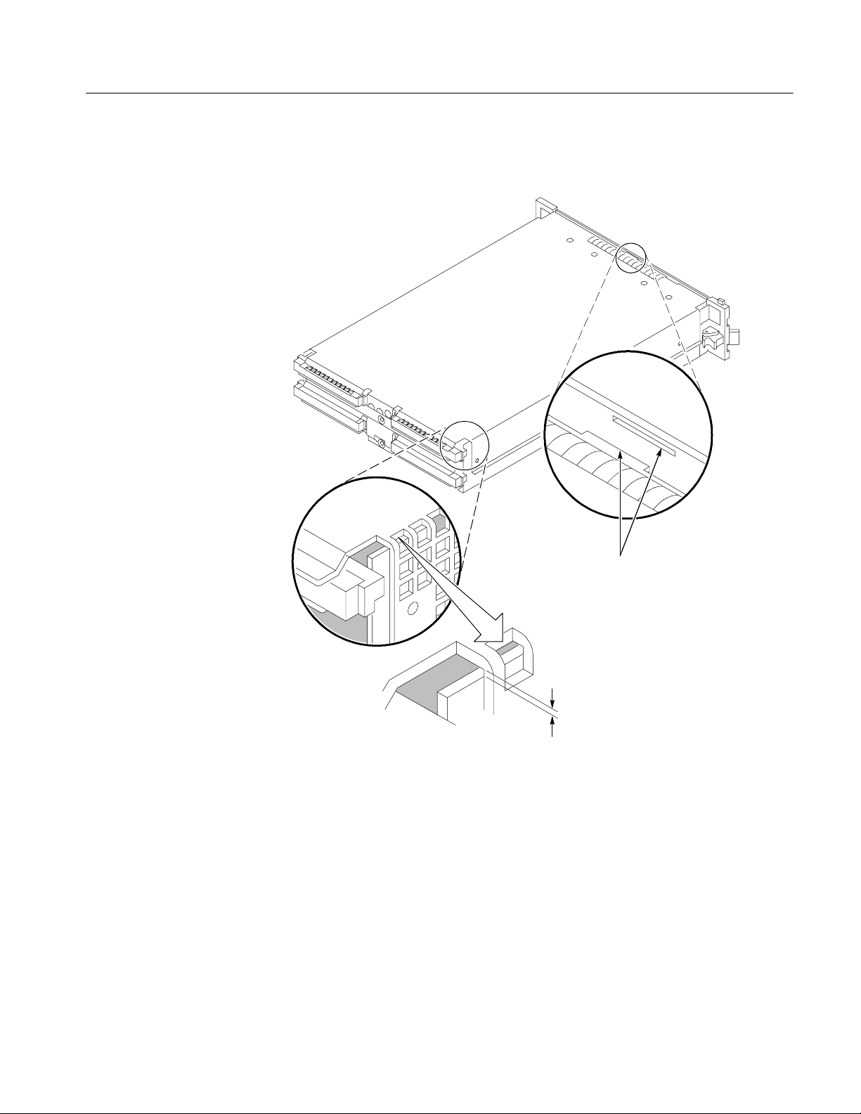
10. Check and tighten all screws to 4 in lbs.
Removal and Installation Procedures
Leave no vertical gap
Figure 6- 9: Seating the cover on the chassis
Make sure tab inserts into
slot on rear of front panel
TLA7AXX/TLA7NAX Logic Analyzer Module Service Manual
6- 17
Page 72
Removal and Installation Procedures
Local Processor Unit Board
You will need a screwdriver with a T-10 tip to complete the following procedures.
NOTE. When placing an order for a replacement LPU board or an LPU
exchange board from the Tektronix Exchange Center, you must supply the model
number, serial number, PowerFlex Option upgrade number and firmware level.
Removal
Use the following procedure and Figure 6--10 to remove the LPU board:
1. Perform the Covers removal procedure (see page 6--13).
2. Remove the five T-10 Torx-drive screws that secure the LPU board to the
chassis.
CAUTION. Handle the LPU board gently to avoid breaking the front panel LED
extension.
3. Carefully lift the LPU board up from the chassis to disengage the 160-pin
connecter from the acquisition board.
4. Move the LPU board away from the front panel until the tabs (Figure 6--10)
clear the front subpanel and then remove the LPU board from the chassis.
6- 18
TLA7AXX/TLA7NAX Logic Analyzer Module Service Manual
Page 73

Removal and Installation Procedures
LPU Board
Screws (5)
Tabs
Installation
160-- pin connecter
Figure 6- 10: LPU board removal
Use the following procedure and Figure 6--10 and Figure 6--11 to install the LPU
board:
1. Place the LPU board (component side down) over the chassis and insert the
tabs on the LPU board into the front subpanel as shown in Figure 6--11.
2. Line up the pins on the 160-pin connector from the LPU board to the
acquisition board and gently press the LPU board in place.
3. Install the five T-10 Torx-drive screws that secure the LPU board to the
chassis.
4. Perform the Covers installation procedure (see page 6--15).
TLA7AXX/TLA7NAX Logic Analyzer Module Service Manual
6- 19
Page 74
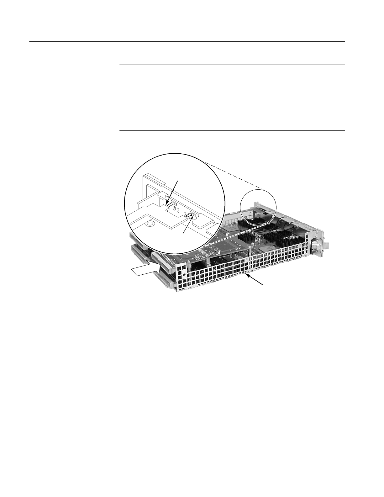
Removal and Installation Procedures
NOTE. After replacing the LPU board, you must verify the proper PowerFlex
level. The PowerFlex configuration information is listed on the side panel of the
logic analyzer module. This information should match the module specific
information on the System Properties tab in the TLA application.
If the PowerFlex level does not match the information on the side panel label,
you must return the entire logic analyzer module to your local Tektronix service
center.
Tabs on
LPU board
Front subpanel
slot
Push forward on
P1 connector
during installation
Chassis
Figure 6- 11: Inserting LPU board tabs into front subpanel
6- 20
TLA7AXX/TLA7NAX Logic Analyzer Module Service Manual
Page 75
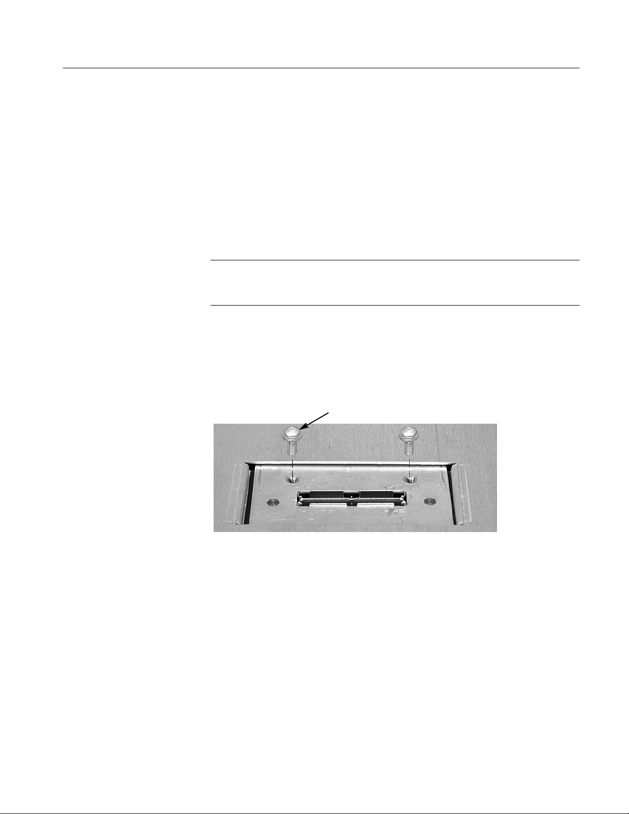
Acquisition Board
Removal and Installation Procedures
You will need a1/4inch nut driver in addition to the T-10 Torx tip screwdriver to
complete the following procedures.
Removal
Use the following procedure and Figure 6--14 to remove the acquisition board:
1. Perform the Covers removal procedure (see page 6--13).
2. Perform the Local Processor Unit Board removal procedure (see page 6--18).
NOTE. The 34-channel and 68-channel modules do not have a left side or right
side merge cable. For these modules, ignore the steps dealing with the merge
cable.
3. Complete the following steps while referring to Figure 6--12 and Figure 6--13
on page 6--22 to remove the merge cable assembly:
a. Turn the chassis over and remove the two T-10 screws from the merge
cable assembly bracket as shown in Figure 6--12.
Screw (2)
Figure 6- 12: Remove the single screw from the merge cable bracket
b. Carefully slide the bracket back underneath the cover until you can grasp
the edge as shown in Figure 6--13.
c. Lift the merge cable assembly bracket out of the hole being careful not to
damage the assembly.
d. Disconnect the merge cable from the acquisition board and set the
assembly aside.
TLA7AXX/TLA7NAX Logic Analyzer Module Service Manual
6- 21
Page 76

Removal and Installation Procedures
slide merge cable
bracket back
Lift merge cable bracket
up and slide out
6- 22
Disconnect cable from
acquisition board
Figure 6- 13: Removing the merge cable assembly
TLA7AXX/TLA7NAX Logic Analyzer Module Service Manual
Page 77
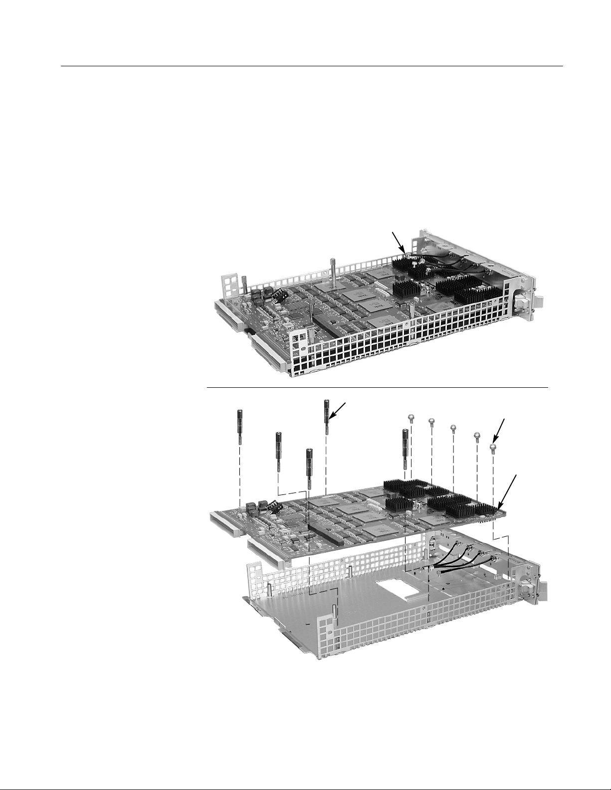
Removal and Installation Procedures
4. Turn the chassis over and then remove the five spacer posts with the
1
/4nut
driver from the acquisition board.
5. For TLA7Axx modules, disconnect the four analog output cables on the
acquisition board. For TLA7NAx modules skip this step.
6. Remove the five T-10 screws from the acquisition board located near the
front of the chassis.
Remove analog
output cables
(TLA7Axx only)
Spacer posts (5)
Screws (5)
Acquisition
board
Figure 6- 14: Removing the acquisition board from the chassis
TLA7AXX/TLA7NAX Logic Analyzer Module Service Manual
6- 23
Page 78

Removal and Installation Procedures
7. Carefully slide the acquisition board away from the front panel until the
probe connectors clear the front panel. Then lift the circuit board out of the
chassis.
Installation
Use the following procedure to install the acquisition board:
1. Place the acquisition board into the chassis.
2. Carefully slide the acquisition board into the chassis until the probe
connectors fit snuggly into the front panel slots.
3. Install five T-10 screws on the acquisition board at the front of the chassis.
4. Install the five spacer posts that secure the acquisition board to the chassis.
5. For TLA7Axx modules, connect the four analog output cables from the front
panel to the acquisition board. For TLA7NAx modules, skip this step.
6. Complete the following steps to install the merge cable assembly (skip these
steps if your instrument does not have a merge cable assembly):
a. Turn the chassis over.
b. Feed the merge cable into the hole and connect it to the circuit board
(refer to Figure 6--13 on page 6--22 if necessary).
c. Carefully slide the merge cable assembly into the hole.
d. Slide the bracket forward and install the tow T-10 screws to hold the
bracket in place.
6- 24
7. Perform the Local Processor Unit Board installation procedure (see
page 6--19).
8. Perform the Covers installation procedure (see page 6--15).
TLA7AXX/TLA7NAX Logic Analyzer Module Service Manual
Page 79

Fuses
There are no user-replaceable parts on any of the circuit boards. If you suspect
that an open fuse exists, there is no easy way of determining the cause of the
open fuse. Most of the fuses are surface mounted and attempting to change the
fuses with improper tools will result in damaging the circuit boards beyond
repair. You should return the circuit board to you local Tektronix service center
for corrective action.
Front and Rear EMI Gaskets
Removal and Installation Procedures
Removal
Use the following procedure to remove the front and rear EMI gaskets:
1. Perform the Cover removal procedure (see page 6--13).
2. For the front EMI gaskets:
a. Locate the gasket to be replaced.
b. Lift the gasket fingers and rotate the gasket off.
3. For the two rear gaskets on the chassis
a. Perform the Local Processor Unit Board removal procedure (page 6--18),
and the Acquisition Board removal procedure (page 6--21).
b. Lift the gasket fingers and rotate the gasket off (see Figure 6--15).
Lift gasket finger
1
Rotate
2
Figure 6- 15: Rear EMI gasket removal
TLA7AXX/TLA7NAX Logic Analyzer Module Service Manual
6- 25
Page 80

Removal and Installation Procedures
Installation
Use the following procedure and Figure 6--16 to install the EMI gaskets:
1. Position each gasket so the gasket fingers face the outside of the module.
CAUTION. To avoid breaking the gasket fingers, do not lift the fingers too high.
2. Pick up each gasket at the end where the gasket finger is formed up. Then
rotate the gasket on. As you do this, lift up any fingers that bind to the
chassis or cover.
3. Slide each gasket gently from side to side to ensure that the gasket snaps in
place.
Slide open end onto module
1
2
Rotate into place lifting any
gasket fingers that bind.
Side EMI Gaskets
Make sure gasket snaps into
3
holes by pulling on gasket
Figure 6- 16: Rear EMI gasket replacement
4. Reinstall the Acquisition board and the LPU board if you removed them to
install the rear EMI gaskets (see pages 6--19 and 6--24).
5. Install the module covers. (see page 6--15).
To remove the side EMI gaskets, remove the covers and circuit boards as
necessary to access the EMI gaskets (refer to Figure 10--1 on page 10--4 for the
gasket locations). Pop the EMI gaskets out of the cover.
To install the side EMI gaskets, pop them into place on the covers.
6- 26
TLA7AXX/TLA7NAX Logic Analyzer Module Service Manual
Page 81
Troubleshooting
WARNING. Before performing this or any other procedure in this manual, read
the General Safety Summary and S ervice Safety Summary found at the
beginning of this manual. Also, to prevent possible injury or damage to
electrical components, read Preventing Electrostatic Discharge on page 6--1.
This section contains information and procedures designed to help isolate faults
to within the logic analyzer module. The process is as follows:
1. Review Check for Common Problems, beginning on page 6--28, to eliminate
easytofindproblems.
2. Perform procedures outlined in Eliminate Other Problem Sources, beginning
on page 6--30, to eliminate the mainframe, probes, and other modules as the
source of the fault(s).
3. Perform the Troubleshoot the Logic Analyzer Module procedure, beginning
on page 6--31, to identify the failed replaceable part within the module.
If you replace a faulty circuit board or assembly found using these procedures,
you must follow any verification and adjustment procedures identified in
Table 6--6 on page 6--37 for the replaced board.
Service Level
This section supports isolation of faults within the logic analyzer module to the
replaceable-part level that’s reflected in the replaceable parts lists in Chapter 10.
In most cases, faults are isolated to circuit boards or assemblies, but not to
individual components on those boards. (See Strategy for Servicing on page
xvii.)
Fault isolation is supported to the following circuit boards and replaceable parts:
H LPU board
H Acquisition board
TLA7AXX/TLA7NAX Logic Analyzer Module Service Manual
6- 27
Page 82
Troubleshooting
Required Documentation
You may need to refer to additional service manuals to isolate faults. In addition,
other manuals and other sections in this manual contain instructions you will
need to complete repairs after locating a faulty part. For a list of supplemental
documentation, refer to the following table.
Manual or Section Purpose
TLA715 Portable Mainframe Service Manual
or TLA721 Benchtop Mainframe & TLA7XM
Expansion Mainframe Service Manual
To eliminate benchtop or portable mainframe
as problem source (whichever configuration is
in use)
TLA700 Series Logic Analyzer Installation
Manual
TLA7UP Mainframe Field Upgrade Instruction
Manual
Check for Common Problems
Use Table 6--4 to quickly isolate possible failures. The table lists problems
related to the logic analyzer module and possible causes. The list is not
exhaustive, but it may help you eliminate a problems that are easy to fix.
CAUTION. To avoid damaging the logic analyzer module or the mainframe, be
sure to power down the mainframe before removing or reinstalling any modules.
To remove and reinstall modules in mainframe
To reinstall Windows 2000, the TLA appl ication software on mainframes or to upgrade
module firmware when required
6- 28
TLA7AXX/TLA7NAX Logic Analyzer Module Service Manual
Page 83
Troubleshooting
Table 6- 4: Failure symptoms and possible causes
Symptom Possible cause(s)
Mainframe does not
power on
Mainframe does not boot H Non-system disk or floppy in external drive; make sure logic
Modules not recognized H Modules not fully inserted; make sure front of module is flush
H Power connection faulty; check or substitute power cord
H Fuse blown; check line fuse
H Mainframe power supply failure; contact local Tektronix service
center
H Mainframe controller is not installed properly (or not at all)
analyzer boots from hard drive (Refer to the TLA700 Series
Logic Analyzer Installation Manual for software reinstallation
procedures)
H Hard drive failure or corrupted files on hard drive; contact local
Tektronix service center
with front panel
H Mainframe power supply failure; contact local Tektronix service
center
H Corrupted module firmware; reinstall firmware. Refer to the
TLA7UP Mainframe Field Upgrade Instruction Manual for
information on reinstalling the latest firmware
H Module logical address switches set to 00. Reset the switches
to FF.
Controller does not
power on
Module does not pass the
normal power on diagnostics (READY indicator not
green)
Module loses settings
when power is turned off
Module will not acquire
data or the acquired data
is incorrect
H Module not fully inserted; make sure front of module is flush
with front panel
H Module failure; try substituting a known-good controller module
and if necessary, contact local Tektronix service center
H Module not fully inserted; make sure front of module is flush
with front panel
H Module failure; see Troubleshoot the Logic Analyzer Module,
or contact local Tektronix service center
H Open fuses on logic analyzer module circuit boards
H Module failure; see Troubleshoot the Logic Analyzer Module,
or contact local Tektronix service center
H NV RAM failure; refer to page 6--18 for local processor unit
board replacement instructions
H Module failure; see Troubleshoot the Logic Analyzer Module,
or contact local Tektronix service center
H Faulty probe, leadset, or probe adaptor
TLA7AXX/TLA7NAX Logic Analyzer Module Service Manual
6- 29
Page 84

Troubleshooting
Eliminate Other Problem Sources
The logic analyzer module is part of the Tektronix Logic Analyzer Family, which
consists of modules installed in either a benchtop or portable mainframe. The
following procedures will help you eliminate the mainframe and other modules
as possible sources of failures.
Substitute a Good Module
If you have available a known-good logic analyzer module, perform the
following procedure:
1. Remove the suspect logic analyzer module from the mainframe.
2. Install a known-good logic analyzer module in the same slot as the suspected
module (verify that address switches on the rear of the module are set to
same address as the module that you are replacing).
3. Power-on the logic analyzer and check for normal operation.
4. If the failure symptoms are still present with the known-good logic analyzer
module installed, the problem most likely is in the mainframe or in the
attached probes, not in the logic analyzer module.
5. To eliminate the probes, use known-good probes and verify that the probes
are properly connected to the target system.
NOTE. Viewing the diagnostic window from the TLA application may help you
isolate failures to individual modules or to the mainframe.
6. If the logic analyzer operates normally with the known-good logic analyzer
module and with known-good probes, the suspect logic analyzer module
needs to be repaired. Refer to Troubleshoot the Logic Analyzer Module on
page 6--31 for additional troubleshooting procedures.
Probe-Level Troubleshooting
6- 30
If the logic analyzer module acquires no data or faulty data, the probes may be at
fault. Perform the following procedure to isolate faults to a probe or to the logic
analyzer module.
NOTE. The procedure below requires that the logic analyzer is functional and
operates normally when the modules are installed.
1. Verify that the probe is correctly connected to the module and to the target
system.
TLA7AXX/TLA7NAX Logic Analyzer Module Service Manual
Page 85

2. Move the suspected probe to another probe connector and observe if the
problem follows the probe. If the problem does not follow the probe, the
module may be faulty.
3. Substitute the suspected probe with a known good probe and observe if the
problem is still present. If the problem still occurs, the module may be
faulty. Refer to Troubleshoot the Logic Analyzer Module to isolate the
problems within that module.
4. If you are using a general purpose probe with lead sets and you have
determined that the probe is faulty, try to isolate the problem to an individual
channel. A faulty channel may indicate a faulty probe podlet. Isolate faulty
podlets by switching single podlets and observing if the problem tracks with
the suspected podlet.
Troubleshoot the Logic Analyzer Module
Follow the procedure in this section to identify the failed part within the logic
analyzer module.
Troubleshooting
Equipment Required
Preparation
Calibration and Diagnostic
Procedures
This procedure requires that the module is installed in a fully functional
mainframe. If you have not determined that the mainframe is functional, or if
you suspect the problem might be in a probe or in another module, refer to
Eliminating Other Problem Sources.
The basic troubleshooting procedures require minimal test equipment. There are
no accessible test points to measure voltages. An ohmmeter is recommended for
checking fuses.
The fault isolation procedure requires that you:
H Recognize codes flashed by the front-panel LEDs during power up
H Are familiar with the power-on diagnostics
To fill these requirements, read the topics below before performing the Fault
Isolation Procedure on page 6--33.
The following calibration and diagnostic procedures will help you diagnose
problems.
Self Calibration. Use self calibration to calibrate the installed modules. R un the
self calibration after a minimum of a 30 minute warm-up and prior to running the
extended diagnostics. For more information on when to run the self calibration,
refer to Self Calibration on page 5--1.
TLA7AXX/TLA7NAX Logic Analyzer Module Service Manual
6- 31
Page 86

Troubleshooting
Power-On Diagnostics. Power-on diagnostics check basic functionality of the
logic analyzer at every power on. If any failures occur at power on, the screen
displays the calibration and diagnostics property sheet.
If there are no diagnostic failures when you power on the logic analyzer, you can
display and run the calibration and diagnostics property sheet by selecting
Calibration and Diagnostics from the System menu.
Extended Diagnostics. The extended diagnostics execute more thorough tests than
the power-on diagnostics. Using the extended diagnostics, you can do the
following tasks:
H Run tests individually or as a group
H Run tests once or continuously
H Run tests until failures occur
NOTE. Certain diagnostic tests will fail if probes are attached. For best results,
run the diagnostics with probes disconnected from the module.
To run the extended diagnostics, do the following steps:
1. Disconnect the probes from the logic analyzer module.
2. Start the TLA application if it is not already running.
3. From the System menu, select Calibration and Diagnostics.
4. Select the Extended Diagnostics property page.
5. Select the individual tests, group of tests, or all tests.
6. Click the Run button.
While the tests are executing, the word Running displays adjacent to the tests.
When the tests are complete, either a Pass or Fail indication displays adjacent to
each test.
Merged Modules. The extended diagnostics include a special merge test that
verifies the correct pipeline adjustment for the master module, inside slave
module, and outside slave module. This test does not require the modules to be
physically merged together.
Every time modules are merged in the System Configuration window, a
calibration is performed between the merged modules. An error message will
appear if there are any problems with the merge cables, circuit board traces, or if
the calibration fails.
6- 32
TLA7AXX/TLA7NAX Logic Analyzer Module Service Manual
Page 87

Troubleshooting
Fault Isolation Procedure
The Primary Troubleshooting Tree (Figure 6--17 on page 6--34) provides
troubleshooting steps that test the logic analyzer module. Use the following
procedure with that tree:
To determine if module is recognized, perform the following steps:
1. Install the logic analyzer module into a known-good mainframe.
2. Before you power on the mainframe, look at the READY, ACCESS ED
ARM’D, and TRIG’D front panel indicators.
3. Power on the mainframe and note how the front panel indicators respond.
a. Verify that the green READY indicator turns on while the diagnostics
are being checked. If the green READY indicator does not turn on, the
module is not being recognized which indicates possible problems on the
LPU board.
b. Verify that after a few seconds the ACCESSED indicator turns on. The
indicator stays on while the module is accessed by the controller. After
the System window displays, the indicator blinks anytime the controller
accesses the module.
4. If steps 3a and 3b are verified, the module is recognized; if not verified, the
module is not recognized. Proceed as the troubleshooting tree instructs.
5. If diagnostic failures occur, replace the circuit board indicated by the
troubleshooting tree. For further confirmation, you can correlate the failed
test displayed with a board using Table 6--5 on page 6--35. You should also
first check the “special cases” of diagnostic failures below:
H Note from the tree, that if all the diagnostics pass, but self calibration
fails, replace the Acquisition board.
H If any of the Kernel test groups fail (ROM check, LPU RAM, LPU
Address decode, etc.) replace the LPU board.
H If the kernel group passes, but there are other failures, replace the
Acquisition board. Also, ensure that the probes are disconnected from
the module before running the diagnostics.
H If multiple tests fail, the problem could be power-supply related
problems or the mainframe. If replacing the acquisition board does not
remedy the failures, try replacing the LPU board.
NOTE. Due to the module design, there are no accessible test points on the
module to connect external test equipment, to help isolate faults to an individual
circuit board.
TLA7AXX/TLA7NAX Logic Analyzer Module Service Manual
6- 33
Page 88

Troubleshooting
6. Use the Removal and Installation Procedures that begin on page 6--11 to
replace the faulty circuit board.
7. Refer to Table 6--6 on page 6--37 after module replacement and perform all
verification and adjustment procedures identified for the replaced module.
Primary Troubleshooting
Chart
Start TLA application
Module
recognized?
Yes
Run extended
diagnostics
Kernel tests
pass?
Yes
Other test fail?
No
No
No
No
Yes
Replace LPU
board
Replace
acquisition board
Address
switches set to
00?
No
Faulty
mainframe?
No
Faulty
module
firmware?
No
Replace LPU
board
Yes
Yes
Yes
Set switches
to FF
Repair
mainframe
Reinstall
firmware
6- 34
Self
calibration
fail?
Yes
Replace
acquisition board
No
Good module
Figure 6- 17: Primary troubleshooting chart
TLA7AXX/TLA7NAX Logic Analyzer Module Service Manual
Page 89

Troubleshooting
Diagnostics Table
Table 6--5 can help you isolate problems to one of the circuit boards in the
module (use the Removal and Installation Procedures beginning on page 6--11 to
replace the faulty circuit board):
Table 6- 5: Diagnostic tests
Circuit board Group&test Power on Extended
LPU board Kernel
ROM Check n n
LPU RAM n n
Address Decode n n
NVRAM Check n n
Acquisition board Timestamp
Timestamp Rollover n n
Acquisition RAM Data Bus n n
Acquisition RAM Address Bus n n
Timestamp Acquire n
Clock
Qualifier/Combiner RAM n n
Clock State Machine RAM n n
Acquisition Data Path
Address/Data Bus n n
MagniVu RAM n
Trigger
Internal RAM n n
Trigger Crossbar n n
Signal/Trigger Lines n n
Trigger State Machine Counters n n
Prefill Counter n n
Word Recognizer n n
Transition Detector n n
Clock Group Detector n n
At-speed Transition Detect n
Snapshot n
Acquisition RAM
RAM Select n n
Acquisition Memory n
TLA7AXX/TLA7NAX Logic Analyzer Module Service Manual
6- 35
Page 90
Troubleshooting
Table 6- 5: Diagnostic tests (Cont.)
Circuit board ExtendedPower onGroup&test
Acquisition board Miscellaneous Tests
Acquisition Address Decode n n
Threshold n n
At-speed Async Acquire n
Pseudo Random n
SFDL-1 n n
SFDL-2 n n
PLL n n
Demux n
Edge Detector n
Setup and Hold n
Glitch n
Memory Interface Controller
AD Bus n n
MAR Rollover n n
Waveform 0 n n
Waveform 1 n n
Waveform Pins n n
Waveform Change n n
Search Stack n n
Internal Search n n
External Search n n
Counters n n
RAM Data n n
RAM Address n n
High-Speed Memory Compare n n
Pattern Acquire n
Miscellaneous 2 Tests
Counters n
Timers n
Store Stretch n
Range Recognizer n
Global Storage n
CSM Input Path n
6- 36
TLA7AXX/TLA7NAX Logic Analyzer Module Service Manual
Page 91

Adjustment After Repair
After replacing a circuit board or assembly due to electrical failure, locate the
board removed in Table 6--6 and perform the indicated procedures.
Troubleshooting
Table 6- 6: Requirements after replacement
Board replaced Adjustment required Verification checks
LPU board Adjustment: Powerflex1,
Firmware level restoration
Deskew, Self Calibration,
Threshold tests
Self Calibration, Power-on and
2
Extended Diagnostics, perfor-
,
mance verification procedures
Acquisition board Adjustment: Self Calibration,
Deskew, Threshold tests
1
The PowerFlex restoration or changes can only be made by Tektronix service
personnel.
2
Refer to the TLA7UP Mainframe Field Upgrade Instruction Manual for instructions for
updating module firmware.
Updating or Restoring the Logic Analyzer Firmware
You may have to update the firmware on the logic analyzer module if the module
does not appear in the TLA System window after you have serviced the module
or after you have updated the TLA application software on the mainframe. You
can update multiple modules and module types during a single firmware update
session. The most current firmware resides on a file on the hard disk of the logic
analyzer mainframe.
1. Note which of the modules that may require new firmware.
If any modules are missing from the System window, you can verify the
status of the modules by doing the following steps:
Self Calibration, Power-on and
Extended Diagnostics, performance verification procedures
a. Select System Properties from the System menu.
b. Click the Modules tab.
c. Note the information under the Messages column for any installed
modules. If any modules indicate invalid or similar messages, you must
update the firmware for those modules.
2. Disconnect any probes connected to the modules that you want to update.
3. Exit the logic analyzer application.
TLA7AXX/TLA7NAX Logic Analyzer Module Service Manual
6- 37
Page 92

Troubleshooting
4. Click Start → Programs → Tektronix Logic Analyzer → TLA Firmware
Loader.
5. When you see the pop-up prompting you to cycle the power on the mainframe after completing the upgrade operation, click Yes.
The logic analyzer will scan the mainframe to determine which modules are
installed and which modules can have their firmware upgraded. If you have
any older modules, you may see them listed in the bottom half of the
window. These modules cannot be updated until you install the flash jumper
on the rear of the modules.
6. Select the modules that you want to update from the list of modules
displayed in the Supported list box near the top of the window. If you are
updating more than one module at a time, note the slot location of the
module in the selection box.
7. Select Load Firmware from the Execute menu.
8. Click the TLA7AXX.lod file for TLA7Axx modules or the TLANAX.lod
file for TLA7NAx modules.
NOTE. Be sure to select the proper .lod file for each module. Note the slot
number in the title bar so that you select the correct module for the .lod file.
9. Click OK. You will be asked to confirm your action; click Yes when
prompted.
NOTE. The program will not allow you to load firmware to an incompatible
module. For example, the program will not load DSO firmware to a logic
analyzer module.
The program will load the firmware for each module one at a time. The
process may take several minutes per module.
10. Exit the firmware loader program and power down the logic analyzer. You
must power down the logic analyzer to allow the TLA application to start up
properly.
11. Remove the logic analyzer module from the mainframe.
12. Locate the big label on the side of the module.
13. Record the firmware version that is printed on the label. You will need this
information to see that the firmware version matches the label.
6- 38
14. Reinstall the module in the mainframe and power on the mainframe.
TLA7AXX/TLA7NAX Logic Analyzer Module Service Manual
Page 93
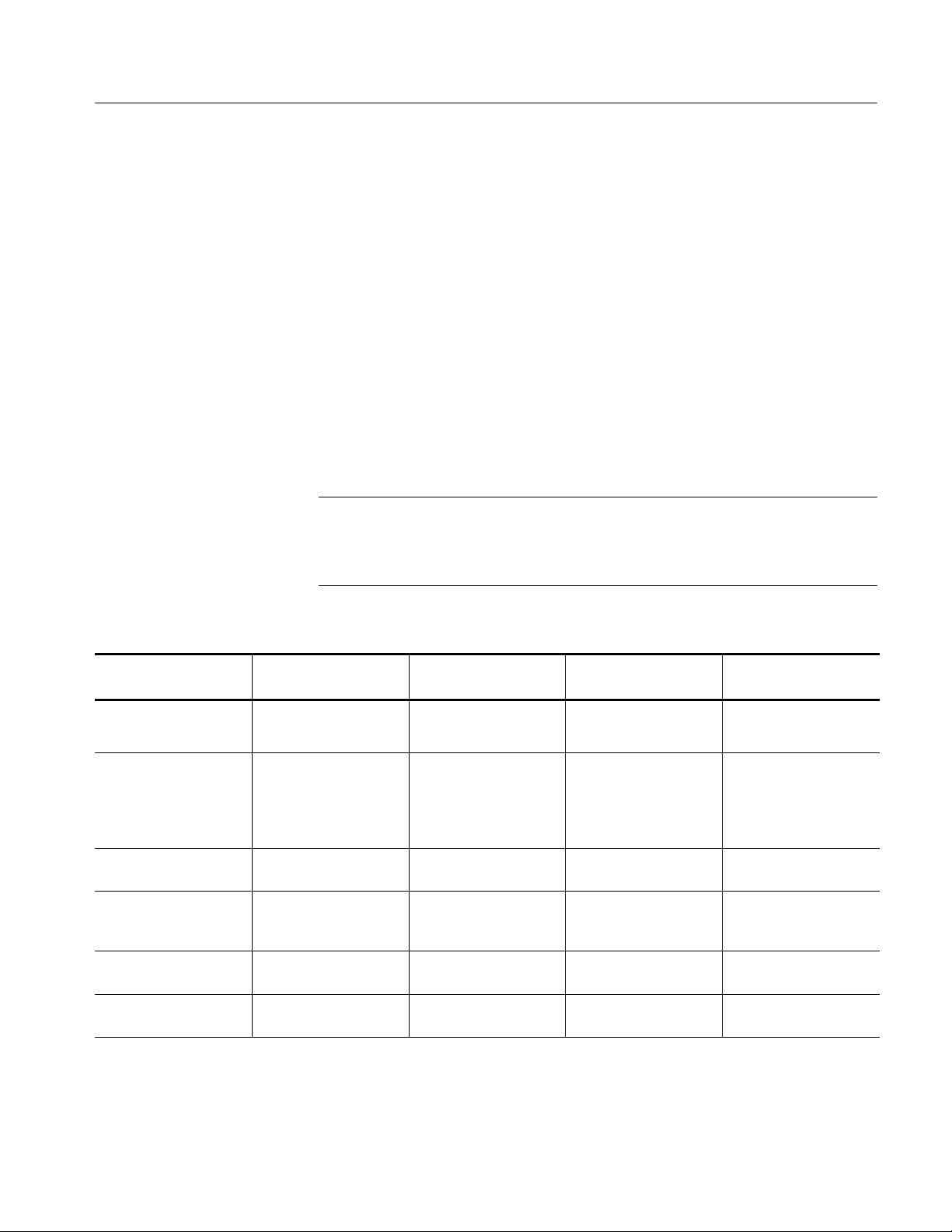
Overview of Procedures
Troubleshooting
15. After the logic analyzer completes the power-on diagnostics, select System
Properties from the System menu.
16. Click the module tab (for example, LA1).
17. Verify that the firmware version for the selected module matches the version
on the label that you recorded in step 13.
18. If the firmware versions do not match, power down the mainframe, remove
the module from the mainframe and update the label.
Table 6--7 provides a brief overview of the troubleshooting, adjustment,
verification, and calibration procedures.
NOTE. Calibration constants are stored in the L PU NVRAM. You must always
perform a new self calibration and have a Tektronix Service technician complete
the adjustment procedures, the performance verification procedures, and the
certification procedures after you replace the LPU board.
Table 6- 7: Troubleshooting overview
Recommended
Procedure
Diagnostics (power on
and extended)
Adjustment:
self calibration and performance verification
Adjustment: deskew After board replacement
Functional verification Incoming inspection
Performance verification Annually or as needed Verifies advertised per-
Calibration (certification) Annual recertification Verifies primary refer-
interval
Incoming inspection
Annually
Annually
As needed
or annually
As needed
Purpose When required Documented
Verifies basic
functionality
Verifies basic
functionality
Time-aligns the data
channels
Verifies front end and
basic functionality
including probes
formance specifications
ences
During troubleshooting Power on Diagnostics,
page 6--32
After board replacement Self Calibration, page
5--1. Adjustments and
performance verification
performed by Tektronix
Service technician
After board replacement Performed by Tektronix
Service technician.
After board replacement Performance Verification,
page 4--1.
After board replacement Performed by Tektronix
Service technician.
After board replacement Performed by Tektronix
Service technician.
TLA7AXX/TLA7NAX Logic Analyzer Module Service Manual
6- 39
Page 94

Troubleshooting
6- 40
TLA7AXX/TLA7NAX Logic Analyzer Module Service Manual
Page 95

Repackaging Instructions
This section contains the information needed to repackage the logic analyzer
module for shipment or storage.
Packaging
If at all possible, use the original packaging to ship or store the instrument. If the
original packaging is not available, use a corrugated cardboard shipping carton
having a test strength of at least 275 pounds (125 kg) and with an inside
dimension at least six inches (15.25 cm) greater than the instrument dimensions.
Add cushioning material to prevent the instrument from moving around in the
shipping container. Seal the shipping carton with an industrial stapler or
strapping tape.
Shipping to the Service Center
Contact the Service Center to get an RMA (return material authorization)
number, and any return or shipping information you may need.
If the instrument is being shipped to a Tektronix Service Center, enclose the
following information:
H The RMA number.
H The owner’s address.
H Name and phone number of a contact person.
H Type of instrument and serial number.
H Reason for returning.
H A complete description of the service required.
NOTE. When ordering the LPU board for exchange or repair, you will need to
supply the above information, including the firmware level and PowerFlex
configuration information.
Mark the address of the Tektronix Service Center and the return address on the
shipping carton in two prominent locations.
TLA7AXX/TLA7NAX Logic Analyzer Module Service Manual
6- 41
Page 96

Repackaging Instructions
Storage
CAUTION. When returning the LPU board separately, be sure to properly support
the narrow LED arm of the circuit board so it will not be damaged during transit
or storage.
The logic analyzer module should be stored in a clean, dry environment. The
following environmental characteristics apply for both shipping and storage:
H Temperature range: --40 °F to +160 °F(--40°Cto+71°C).
H Altitude: To 40,000 feet (12,190 meters).
See the Tektronix Logic Analyzer Family Product Specifications document for a
complete listing of the module environmental characteristics.
6- 42
TLA7AXX/TLA7NAX Logic Analyzer Module Service Manual
Page 97

Options
This chapter lists the advertised options for each logic analyzer module. Refer to
the Mechanical Parts List chapter for a list of standard and optional accessories
for each module.
TLA7AA1, TLA7AA2, TLA7AA3 and TLA7AA4 Options
Table 7--1 lists the options for the TLA7AA1, TLA7AA2, TLA7AA3 and
TLA7AA4 modules.
Table 7- 1: TLA7AA1, TLA7AA2, TLA7AA3 and TLA7AA4 options
Option Descri pti on
1S Increase to 512 Kb memory depth @ 120 MHz state speed
2S Increase to 2 Mb memory depth @ 120 MHz state speed
3S Increase to 8 Mb memory depth @ 120 MHz state speed
4S Increase to 32 Mb memory depth @ 120 MHz state speed
5S Increase to 128 Kb memory depth @ 235 MHz state speed
6S Increase to 512 Kb memory depth @ 235 MHz state speed
7S Increase to 2 Mb memory depth @ 235 MHz state speed
8S Increase to 8 Mb memory depth @ 235 MHz state speed
9S Increase to 32 Mb memory depth @ 235 MHz state speed
AS Increase to 128 Kb memory depth @ 450 MHz state speed
BS Increase to 512 Kb memory depth @ 450 MHz state speed
CS Increase to 2 Mb memory depth @ 450 MHz state speed
DS Increase to 8 Mb memory depth @ 450 MHz state speed
ES Increase to 32 Mb memory depth @ 450 MHz state speed
TLA7AXX/TLA7NAX Logic Analyzer Module Service Manual
7- 1
Page 98
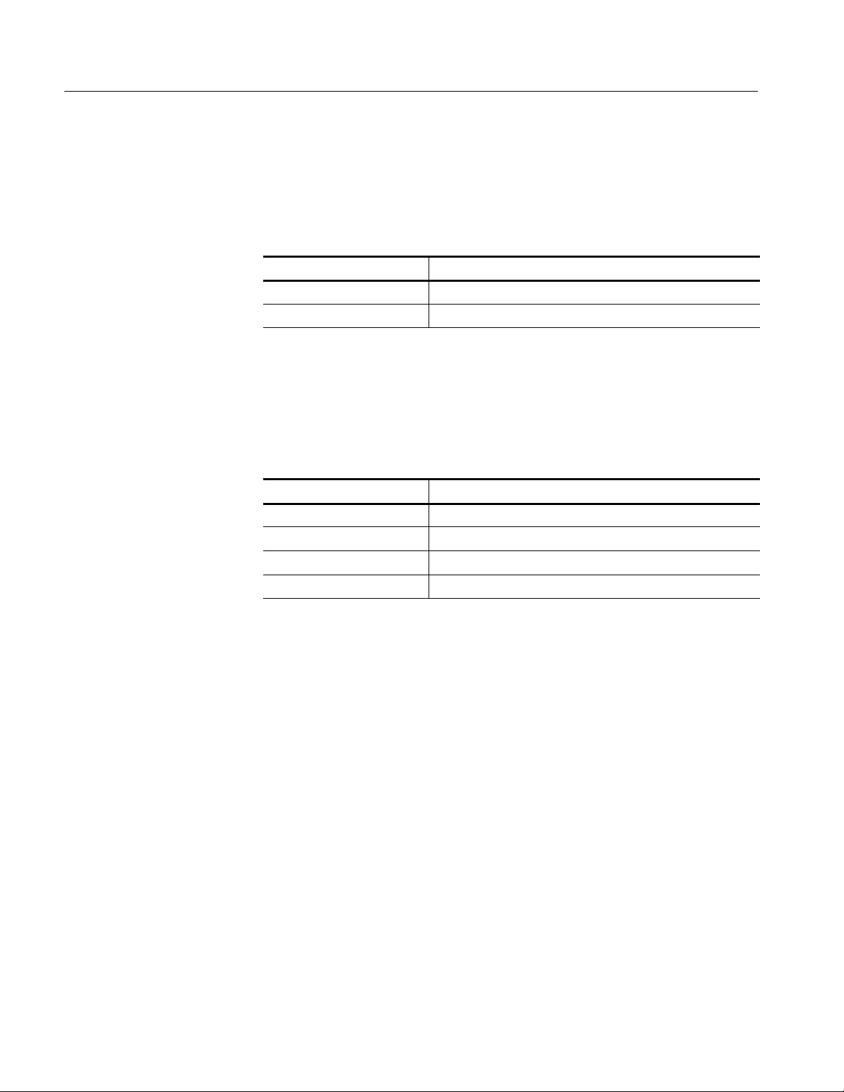
Options
TLA7AB2 and TLA7AB4 Options
Table 7--2 lists the options for the TLA7AB2 and TLA7AB4 modules.
Table 7- 2: TLA7AB2 and TLA7AB4 options
Option Descri pti on
1S Increase to 64 Mb memory depth @ 235 MHz state speed
2S Increase to 64 Mb memory depth @ 450 MHz state speed
TLA7NAX Options
Table 7--3 lists the options for the TLA7NAx modules.
Table 7- 3: TLA7NAx options
Option Descri pti on
7S Increase to 2 Mb record length
8S Increase to 8 Mb record length
9S Increase to 32 Mb record length
45 Increase state speed to 450 MHz
7- 2
TLA7AXX/TLA7NAX Logic Analyzer Module Service Manual
Page 99
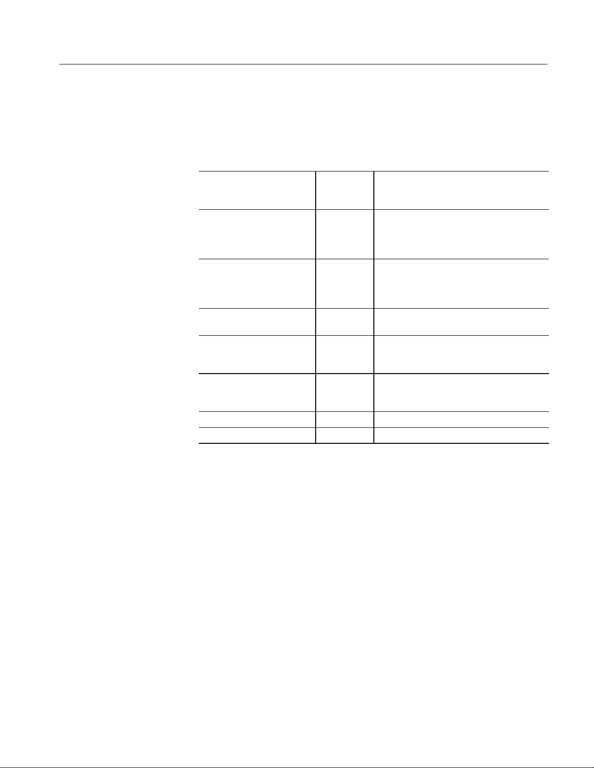
Service Options
Options
Tektronix Service Options are available at the time you order your instrument.
Contact your local Tektronix Sales Office for more information.
Product installation service
Three years of calibration
services
Five years of calibration services
Test data Option D1 Provides initial Test Data Report from factory
Test data Option D3 Provides test data on delivery plus a Test Data
Test data Option D5 Provides test data on delivery plus a Test Data
Three years repair coverage Option R3 Extends product repair warranty to three years.
Five years repair coverage Option R5 Extends product repair warranty to five years.
1
Availability of installation and on-site services depends on the type of product and
may vary by geography.
1
Option IN Provides initial product installation/configura-
tion and start-up training session including
front panel and product familiarization.
Option C3 Provides factory calibration certification on
delivery, plus two more years of calibration
coverage. The instrument will be calibrated
according to its calibration interval.
Option C5 Provides factory calibration certification on
delivery, plus four more years of calibration
coverage. The instrument will be calibrated
according to its calibration interval.
on delivery.
Report for every calibration performed during 3
years of coverage -- requires Option C3.
Report for every calibration performed during 5
years of coverage -- requires Option C5.
TLA7AXX/TLA7NAX Logic Analyzer Module Service Manual
7- 3
Page 100

Options
7- 4
TLA7AXX/TLA7NAX Logic Analyzer Module Service Manual
 Loading...